
Bearing Characteristics and Ground Deformation Computation of Recyclable Steel-Pipe Piles during Pit Excavation

Abstract
:1. Introduction
2. Methodology
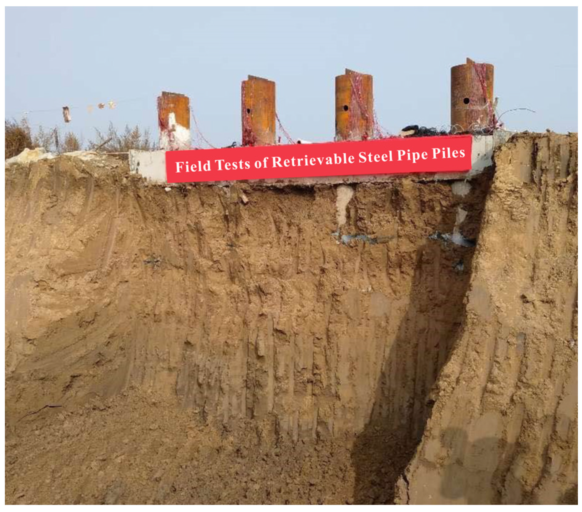
2.1. Field Test
- (1)
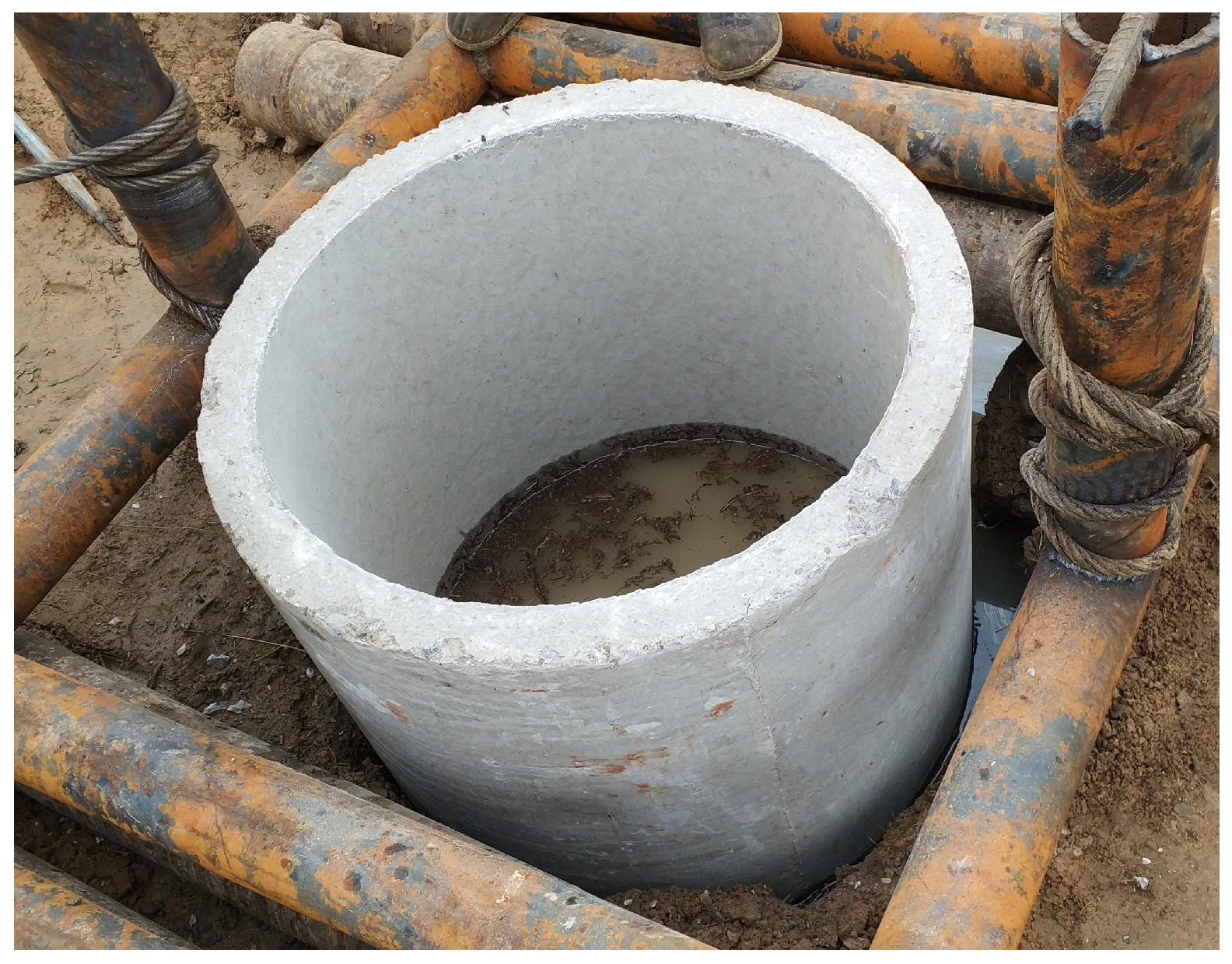
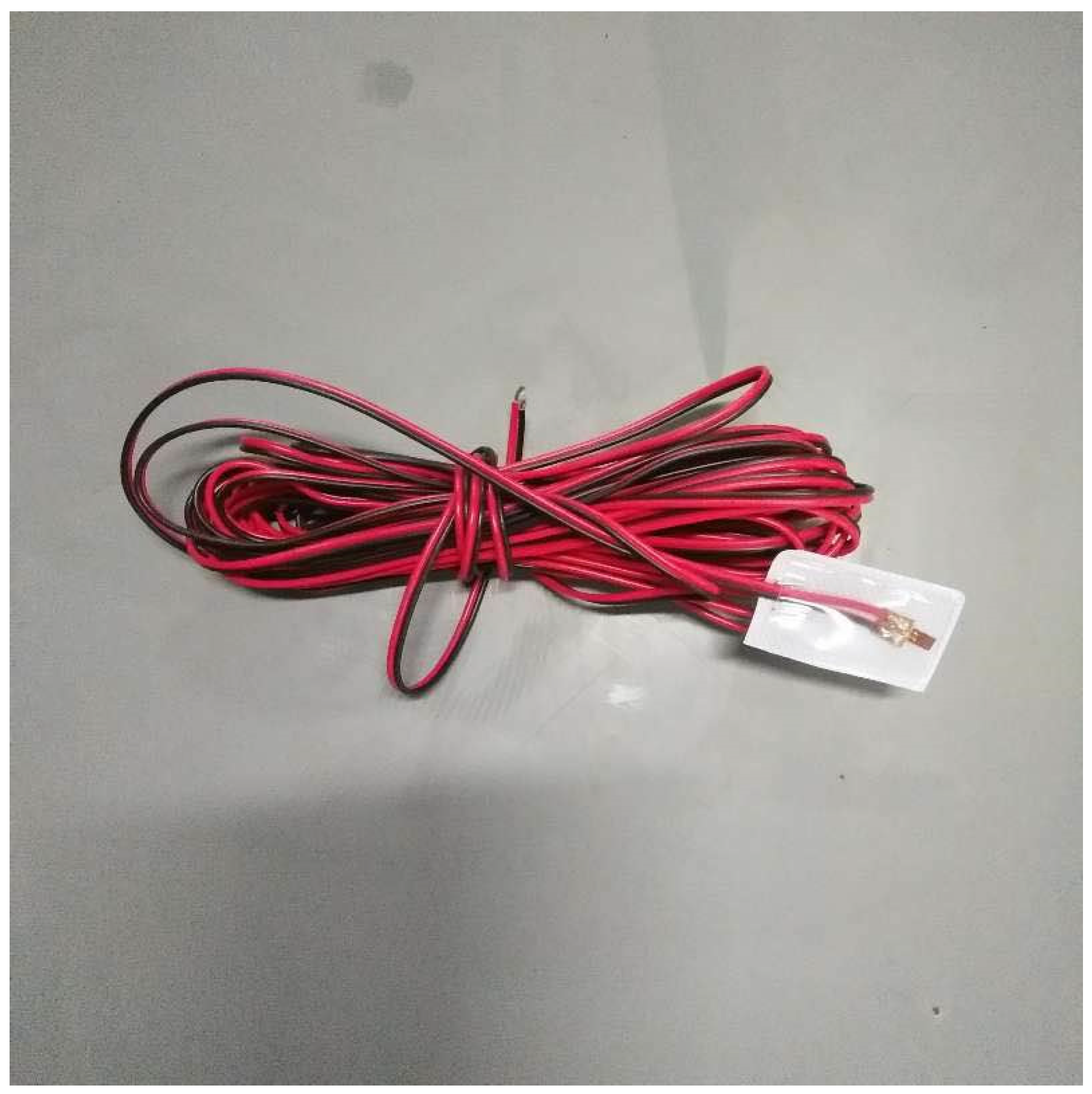
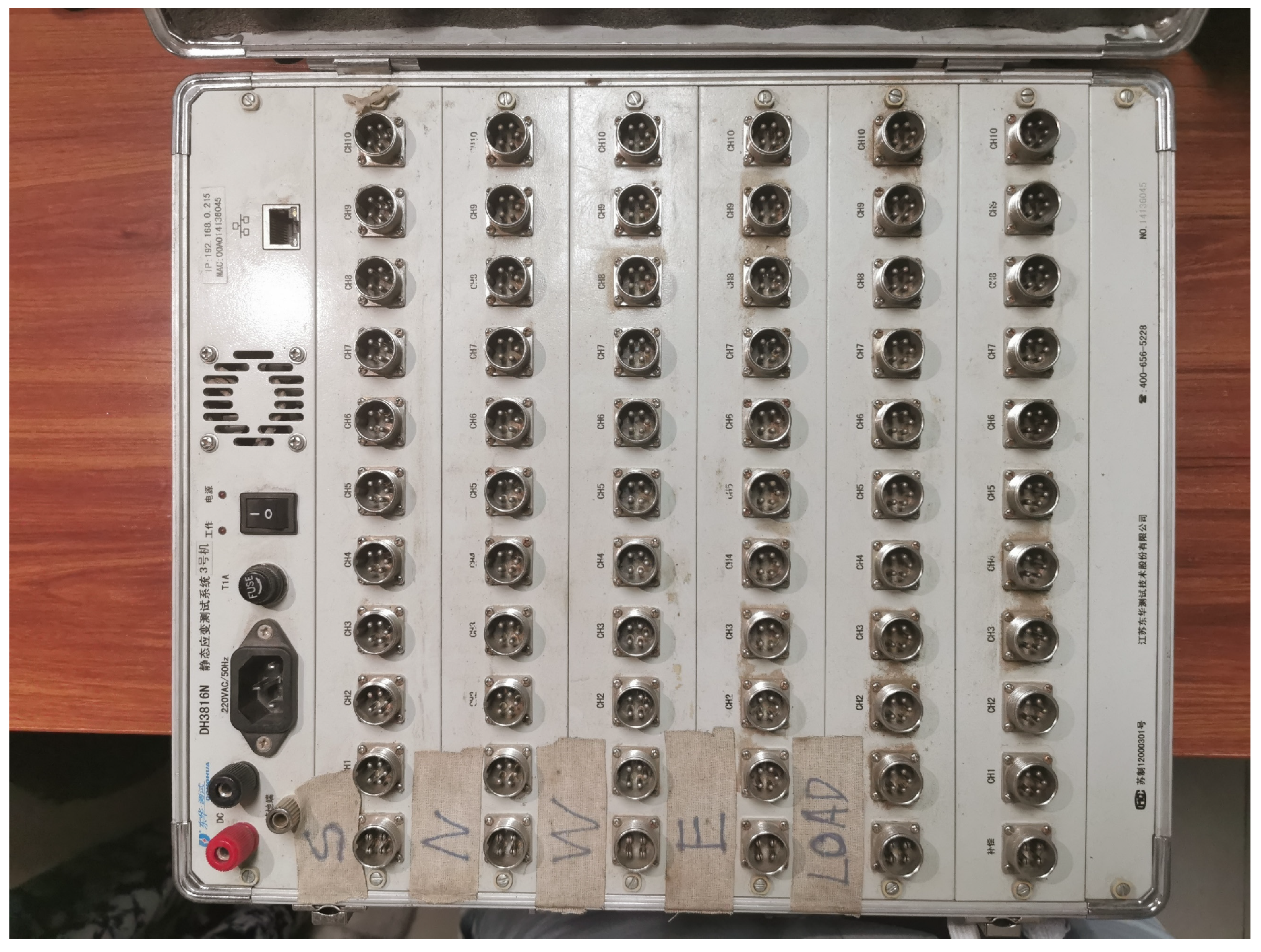
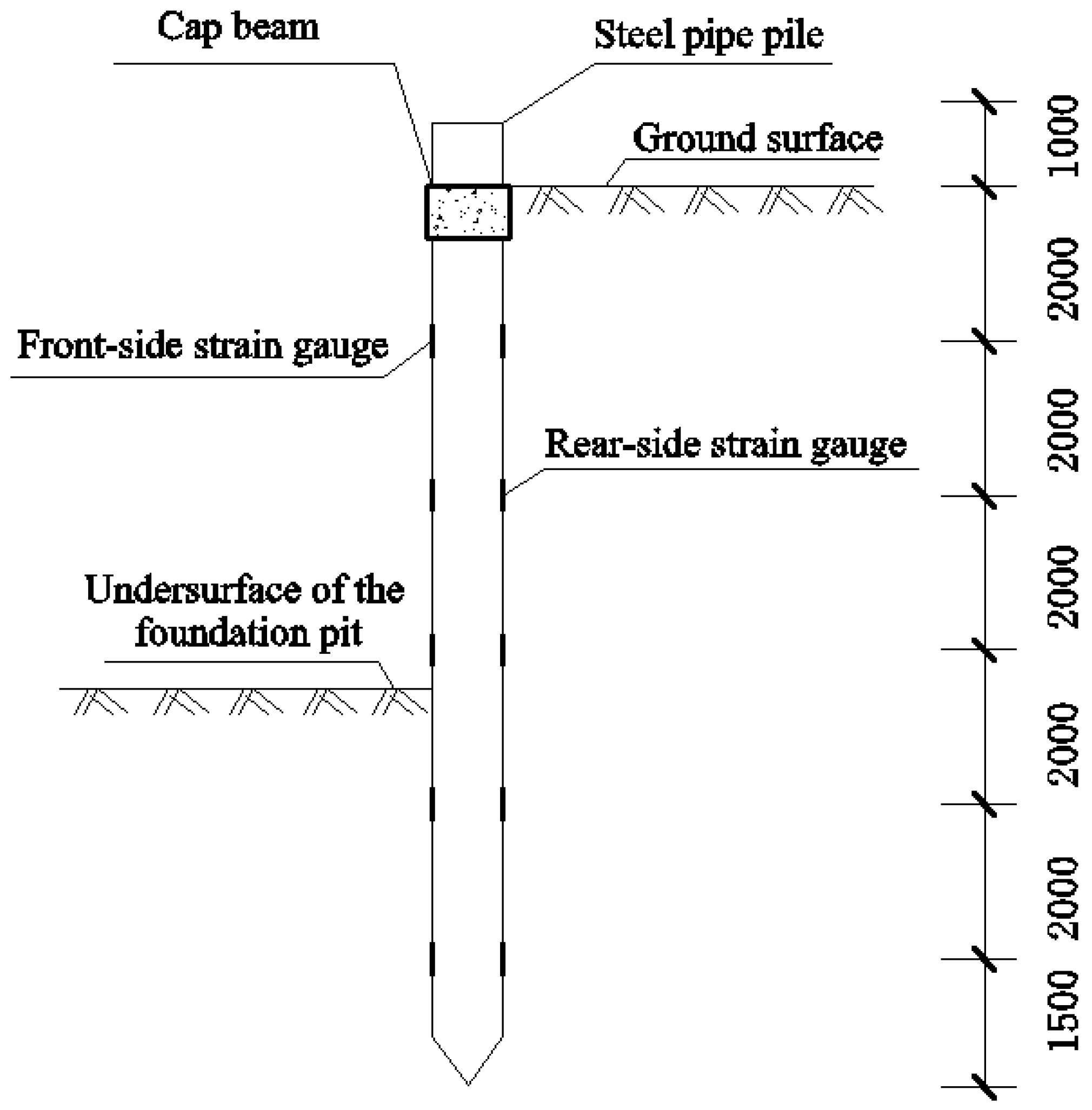
- Layout of the strain gauge on the pile body and monitoring device
- (2)
- Layout of the monitoring points of pile top displacement and monitoring device
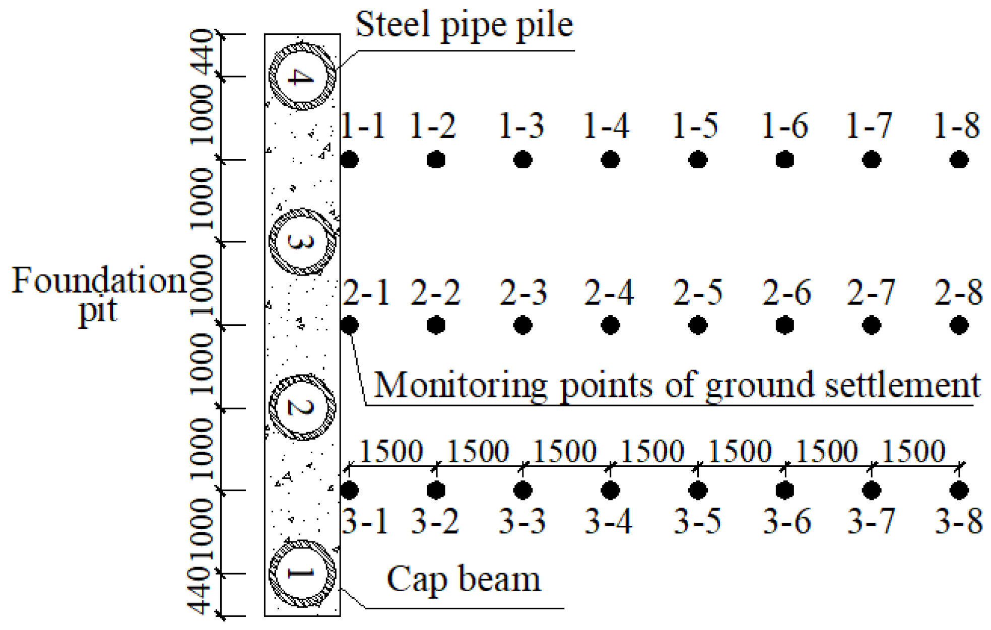
- (3)
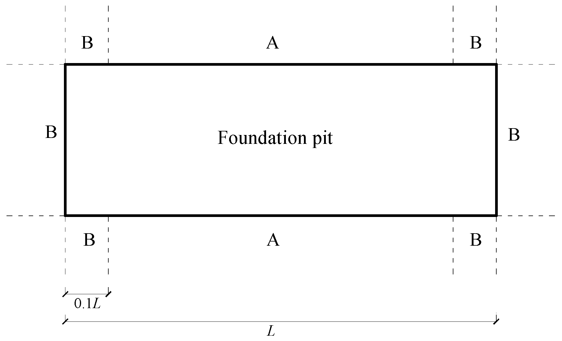
- Layout plan of the monitoring points of the ground surface settlement
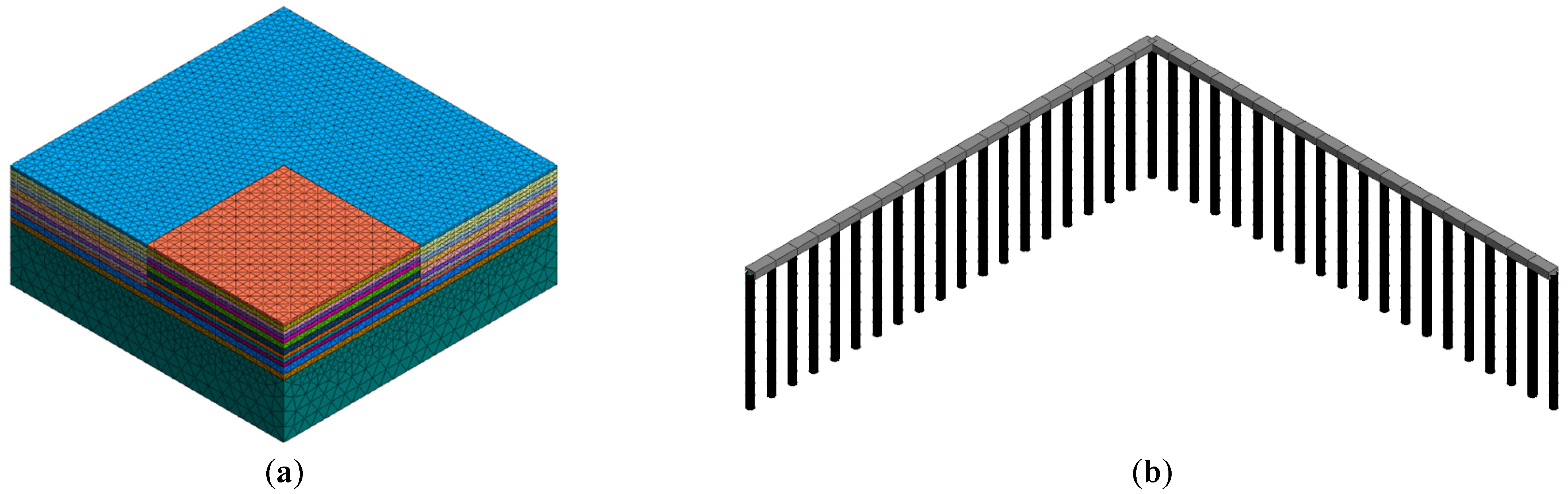
2.2. Finite Element Analysis
3. Results Analysis and Discussion
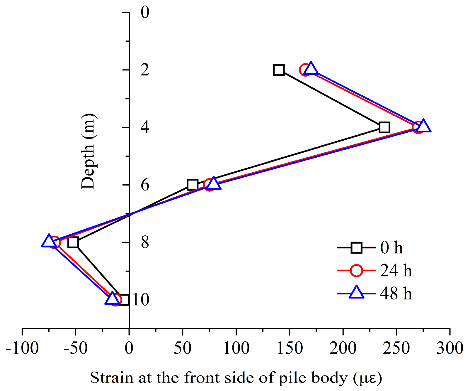
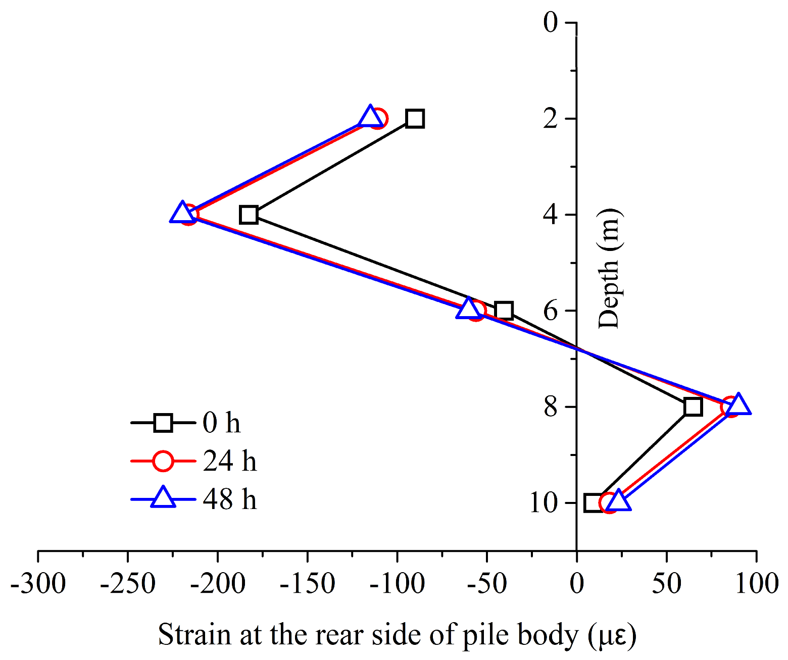
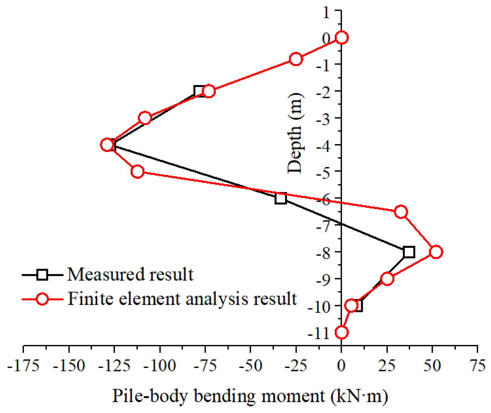
3.1. Pile Strain and Bending Moment
3.2. Cross-Section Strength Analysis of the Pile
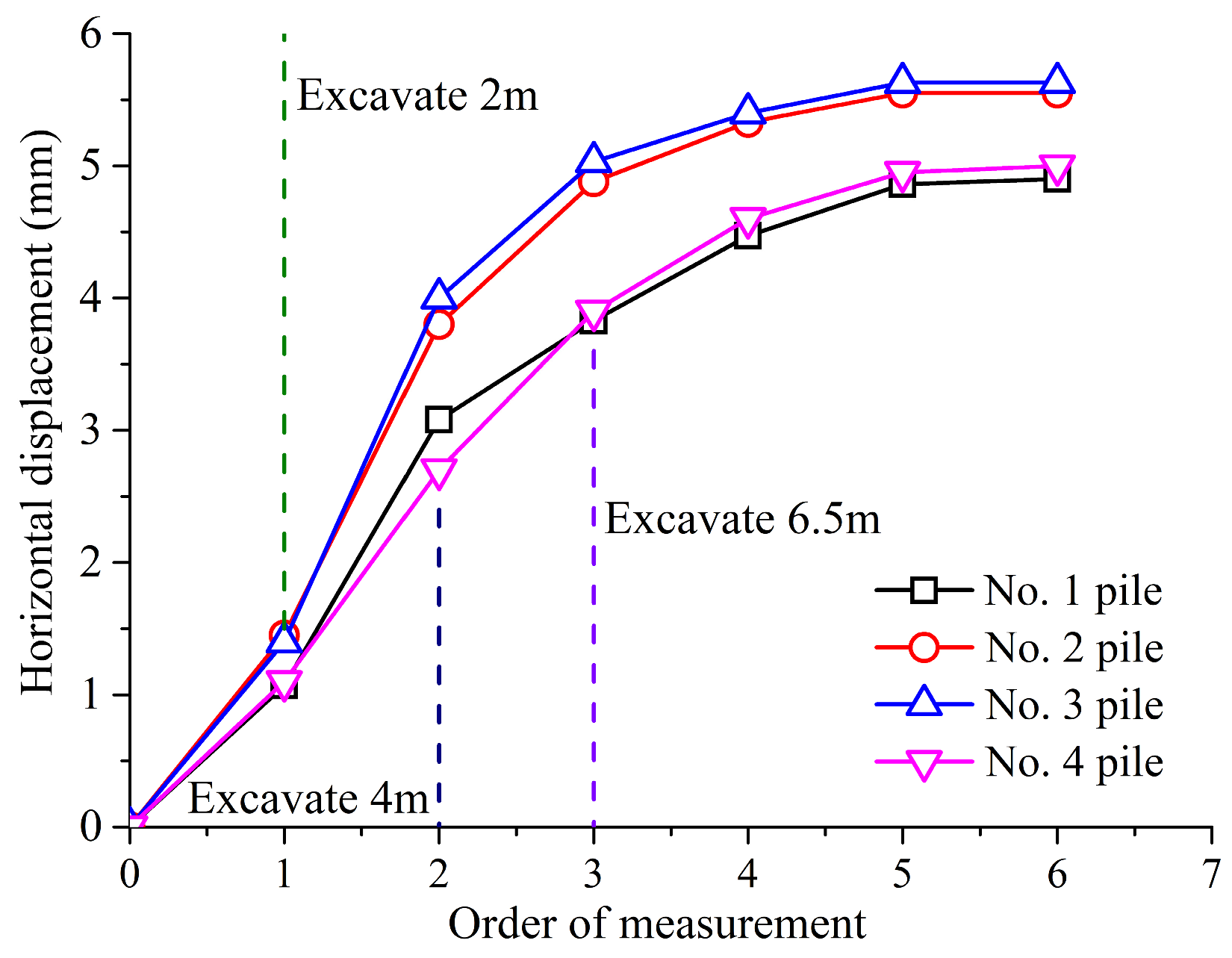
3.3. Analysis of the Horizontal Displacement of the Pile Top
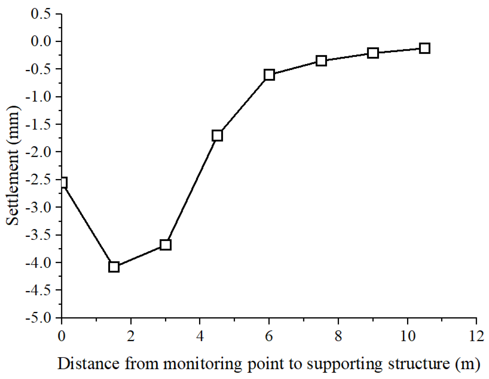
3.4. Analysis of the Ground Surface Settlement
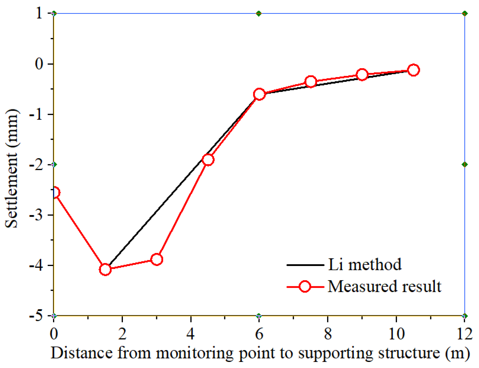
Analysis of Settlement Curve Shape
4. Conclusions
- (1)
- Upon completing the foundation pit excavation, front- and rear-side strains of the pile body were approximately symmetrical. The value of the pile-body strain was 0 near the undersurface of the foundation pit. The pile body also experienced negative bending at the position above the undersurface of the foundation pit. The maximum pile-body strain occurred at 0.62 H below the ground surface. In addition, the pile body went through positive bending at the position below the undersurface of the foundation pit. The maximum pile-body strain occurred at 0.23 H.
- (2)
- During the foundation pit excavation process, the pile body experienced displacement towards the pit. Pile-top displacement gradually increased with the excavation depth. After the excavation, the pile-top displacement reached the maximum value of 5.63 mm.
- (3)
- The ground surface settlement curve caused by the foundation pit excavation presented a “Spoon” shape. In the direction away from the foundation pit, ground surface settlement initially increased. Then, the tendency decreased with the increase in distance. The maximum ground surface settlement occurred at 0.23 H behind the supporting structure. The main influence area of the ground surface settlement caused by foundation pit excavation was 0.92 H.
- (4)
- The calculation result, obtained through the finite element analysis, showed that the pile-body deformation laws were consistent with the measured ones. The maximum normal stress was 56.9 MPa, which was smaller than the design value of steel flexural strength. Therefore, the pile-body structure was safe.
- (5)
- A suitable mathematical expression of ground surface settlement curve shape was proposed. Through a comparison, the proposed formula can express the shape of the settlement curve well.
- (6)
- Given the condition restriction in this test, the obtained ground surface settlement monitoring data were limited. Therefore, in future work, it is necessary to analyze the parameters of mathematical expressions in the case of more abundant monitoring data.
Author Contributions
Funding
Institutional Review Board Statement
Informed Consent Statement
Data Availability Statement
Acknowledgments
Conflicts of Interest
References
- Wang, Z.H.; Zhou, J. Three-dimensional numerical simulation and earth pressure analysis on double-row piles with consideration of spatial effects. J. Zhejiang Univ.-Sci. A Appl. Phys. Eng. 2011, 12, 758–770. [Google Scholar] [CrossRef]
- Dong, Y.P.; Burd, H.J.; Houlsby, G.T. Finite-element analysis of a deep excavation case history. Geotechnique 2015, 66, 1–15. [Google Scholar] [CrossRef]
- Goh, A.T.C.; Zhang, F.; Zhang, W.; Zhang, Y.; Liu, H. A simple estimation model for 3D braced excavation wall deflection. Comput. Geotech. 2017, 83, 106–113. [Google Scholar] [CrossRef]
- Zhang, W.; Goh, A.T.C.; Xuan, F. A simple prediction model for wall deflection caused by braced excavation in clays. Comput. Geotech. 2015, 63, 67–72. [Google Scholar] [CrossRef]
- Zhao, Q.J.; Liu, Z.G. Application of recycling anchor cables in support of excavations. Chin. J. Geotech. Eng. 2012, 34, 480–483. [Google Scholar]
- Li, Z.P.; Huang, M.L.; Wang, J. Study on the Recoverable Anchor Cable Supporting Scheme Optimization Design for Metro Foundation pit. Chin. J. Undergr. Space Eng. 2012, 8, 154–160. [Google Scholar]
- Zhang, J.H. Recycling excavation support system (RESS) for foundation pits. Chin. J. Geotech. Eng. 2012, 34, 287–291. [Google Scholar]
- Xiao, T.L.; He, Y.L. Experimental Study of an Inflatable Recyclable Anchor. Adv. Mater. Sci. Eng. 2018, 2018, 6940531. [Google Scholar] [CrossRef]
- Pan, Y.; Fang, H.; Li, B.; Wang, F. Stability analysis and full-scale test of a new recyclable supporting structure for underground ecological granaries. Eng. Struct. 2019, 192, 205–219. [Google Scholar] [CrossRef]
- Li, Z.; Teng, Y.J.; Li, Q.R. Micro-pile techniques for improvement project of existing buildings. China Civ. Eng. J. 2015, 48, 197–201. [Google Scholar]
- Zhang, M.Y.; Li, S.N.; Peng, W.T. Simulation of vertical bearing characteristics of super-long diameter steel pipe piles based on FLAC3D. Rock Soil Mech. 2011, 32, 2856–2860. (In Chinese) [Google Scholar] [CrossRef]
- Liu, Z.S. Field tests on negative skin friction of steel pipe piles in high backfilling soils. Chin. J. Geotech. Eng. 2015, 37, 337–342. [Google Scholar] [CrossRef]
- Wang, M.Y.; Shan, Z.G.; Rao, X.B. Numerical inversion study on comprehensive capacity of marine steel pipe pile based on field pile loading tests. Chin. J. Geotech. Eng. 2016, 38, 143–148. [Google Scholar] [CrossRef]
- Ou, C.Y.; Hsieh, P.G.; Chiou, D.C. Characteristics of ground surface settlement during excavation. Can. Geotech. J. 1993, 30, 758–767. [Google Scholar] [CrossRef]
- Peck, R.B. Deep excavations and tunneling in soft ground. In Proceedings of the 7th International Conference of Soil Mechanics & Foundation Engineering, Mexico City, Mexico, 1969; pp. 225–290. Available online: https://www.scirp.org/reference/referencespapers?referenceid=1768642 (accessed on 28 June 2024).
- Hsieh, P.G.; Ou, C.Y. Shape of ground surface settlement profiles caused by excavation. Can. Geotech. J. 1998, 35, 1004–1017. [Google Scholar] [CrossRef]
- Wei, G.; Hua, X.X.; Yu, X.F. Construction monitoring analysis of deep foundation pit excavation of a metro station in Hangzhou. Eng. J. Wuhan Univ. 2016, 49, 917–923. [Google Scholar] [CrossRef]
- Goh, A.T.C.; Zhang, R.H.; Wang, W.; Wang, L.; Liu, H.L.; Zhang, W.G. Numerical study of the effects of groundwater drawdown on ground settlement for excavation in residual soils. Acta Geotech. 2019, 15, 1259–1272. [Google Scholar] [CrossRef]
- Zhang, W.; Wang, W.; Zhou, D.; Zhang, R.; Goh, A.T.C.; Hou, Z. Influence of groundwater drawdown on excavation responses—A case history in Bukit Timah granitic residual soils. J. Rock Mech. Geotech. Eng. 2018, 10, 856–864. [Google Scholar] [CrossRef]
- Zhang, W.G.; Goh, A.T.C.; Goh, K.H.; Chew, O.Y.S.; Zhou, D.; Zhang, R. Performance of braced excavation in residual soil with groundwater drawdown. Undergr. Space 2018, 3, 150–165. [Google Scholar] [CrossRef]
- Hong, Y.; Ng, C.; Liu, G.; Liu, T. Three-dimensional deformation behaviour of a multi-propped excavation at a “greenfield” site at Shanghai soft clay. Tunn. Undergr. Space Technol. 2015, 45, 249–259. [Google Scholar] [CrossRef]
- Hsiung, B.-C.B.; Yang, K.-H.; Aila, W.; Hung, C. Three-dimensional effects of a deep excavation on wall deflections in loose to medium dense sands. Comput. Geotech. 2016, 80, 138–151. [Google Scholar] [CrossRef]
- Gong, Y.F.; Yao, A.J.; Li, Y.L.; Li, Y.Y.; Li, Y.N.; Sun, Y.T. Model test study on sliding-toppling composite deformation evolution of anti-dip layered rock slope. Bull. Eng. Geol. Environ. 2023, 82, 194. [Google Scholar] [CrossRef]
- Pakbaz, M.S.; Imanzadeh, S.; Bagherinia, K.H. Characteristics of diaphragm wall lateral deformations and ground surface settlements: Case study in Iran-Ahwaz metro. Tunn. Undergr. Space Technol. 2013, 35, 109–121. [Google Scholar] [CrossRef]
- Li, Y.; Yao, A.; Li, H.; Gong, Y.; Tian, T. Calculation method of multi-stage earth pressure for foundation excavation considering excavation process. Acta Geotech. 2023, 18, 6123–6141. [Google Scholar] [CrossRef]
- Li, Y.-L.; Lu, J.; Yao, A.; Li, H.; Gong, Y.-F. Nonlinear elastic deformation model of belled uplift piles under the coupling effects of groundwater and shear strain relaxation. Comput. Geotech. 2024, 171, 106411. [Google Scholar] [CrossRef]
- Ou, C.-Y.; Shiau, B.-Y.; Wang, I.-W. Three-dimensional deformation behavior of the Taipei National Enterprise Center (TNEC) excavation case history. Can. Geotech. J. 2000, 37, 438–448. [Google Scholar] [CrossRef]
- Li, D.; Li, Z.; Tang, D. Three-dimensional effects on deformation of deep excavations. Geotech. Eng. 2015, 168, 551–562. [Google Scholar] [CrossRef]
- Teo, P.L.; Wong, K.S. Application of the hardening soil model in deep excavation analysis. IES J. Part A Civ. Struct. Eng. 2012, 5, 152–165. [Google Scholar] [CrossRef]
- Chen, Y.M.; Xu, D.P. FLAC/FLAC3D Foundation and Engineering Example; China Water & Power Press: Beijing, China, 2013. [Google Scholar]
- GB 50497-2009; Technical Code for Monitoring of Building Excavation Engineering. China Planning Press: Beijing, China, 2009.


| Name | Thickness (m) | Poisson Ratio | Unit Weight (kN/m3) | Cohesion (kPa) | Internal Friction Angle (°) | Compression Modulus (MPa) |
|---|---|---|---|---|---|---|
| Miscellaneous fill | 0.8 | 0.35 | 16.5 | 0 | 8 | 5 |
| Clayey silt | 5.7 | 0.25 | 19.7 | 9 | 16 | 11 |
| Sandy silt | 4.5 | 0.26 | 19.9 | 14 | 18 | 14 |
| Fine sand | 1.8 | 0.27 | 19.5 | 0 | 30 | 30 |
| Silty clay | 17.2 | 0.26 | 20 | 20 | 22 | 26 |
| Name | Elastic Modulus (MPa) | Poisson Ratio | Unit Weight (kN/m3) |
|---|---|---|---|
| Steel-pipe pile | 206,000 | 0.3 | 78 |
| Cap beam | 28,361 | 0.25 | 25 |
Disclaimer/Publisher’s Note: The statements, opinions and data contained in all publications are solely those of the individual author(s) and contributor(s) and not of MDPI and/or the editor(s). MDPI and/or the editor(s) disclaim responsibility for any injury to people or property resulting from any ideas, methods, instructions or products referred to in the content. |
© 2024 by the authors. Licensee MDPI, Basel, Switzerland. This article is an open access article distributed under the terms and conditions of the Creative Commons Attribution (CC BY) license (https://creativecommons.org/licenses/by/4.0/).
Share and Cite
Lu, J.; Li, Y.; Yao, A. Bearing Characteristics and Ground Deformation Computation of Recyclable Steel-Pipe Piles during Pit Excavation. Appl. Sci. 2024, 14, 5727. https://doi.org/10.3390/app14135727
Lu J, Li Y, Yao A. Bearing Characteristics and Ground Deformation Computation of Recyclable Steel-Pipe Piles during Pit Excavation. Applied Sciences. 2024; 14(13):5727. https://doi.org/10.3390/app14135727
Chicago/Turabian StyleLu, Jian, Yanlin Li, and Aijun Yao. 2024. "Bearing Characteristics and Ground Deformation Computation of Recyclable Steel-Pipe Piles during Pit Excavation" Applied Sciences 14, no. 13: 5727. https://doi.org/10.3390/app14135727