
Enhancing Biogas Plant Efficiency for the Production of Electrical and Thermal Energy

 ,
,  , , ,
, , ,
Abstract
Featured Application
Abstract
1. Introduction
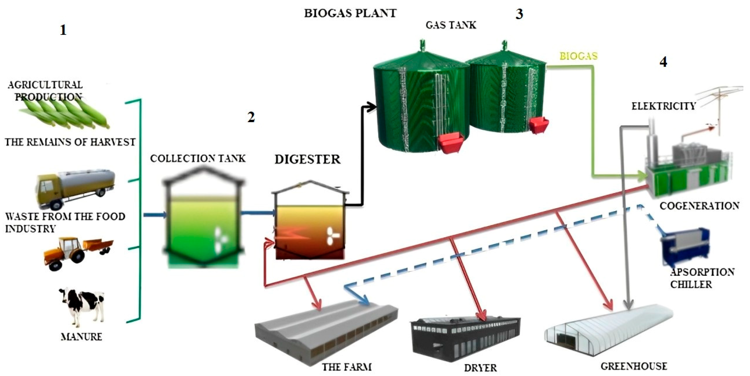
- Biogas production prevents methane emissions into the atmosphere, which is the best way to reduce global warming. When we talk about a biogas plant, first of all we are referring to a gas with a large amount of methane in it, which is produced by fermentation of various organic substances [8,19,20].
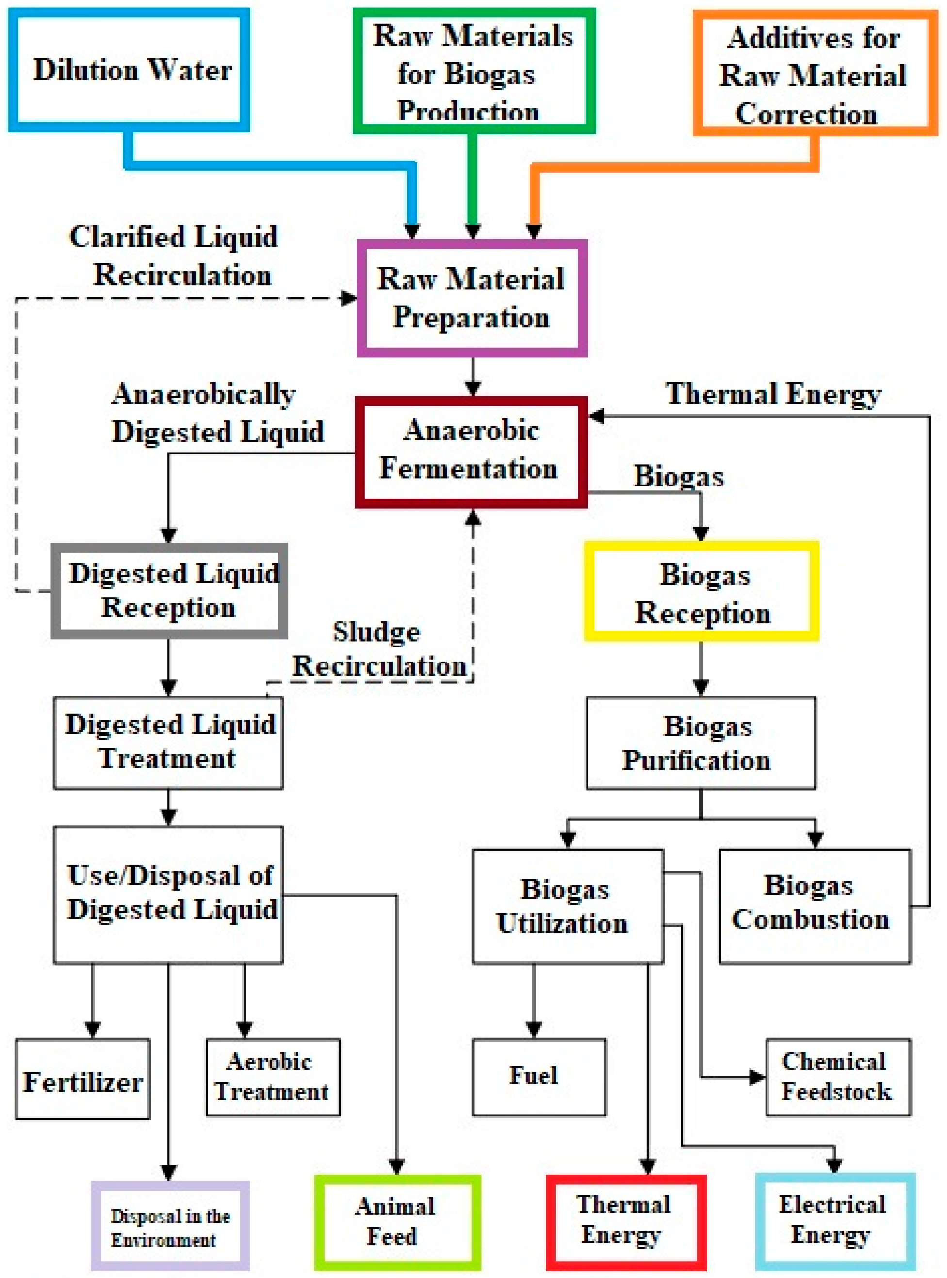
2. Materials and Methods
- Preparation of raw material for processing;
- Anaerobic digestion;
- Storage, transport, and use of boiled liquid;
- Storage, purification, and use of biogas.
- Animal flour with a dry matter content of 92–98%;
- Corn silage with a dry matter content of 30–35%;
- Molasses with a dry matter content of 84–88%.
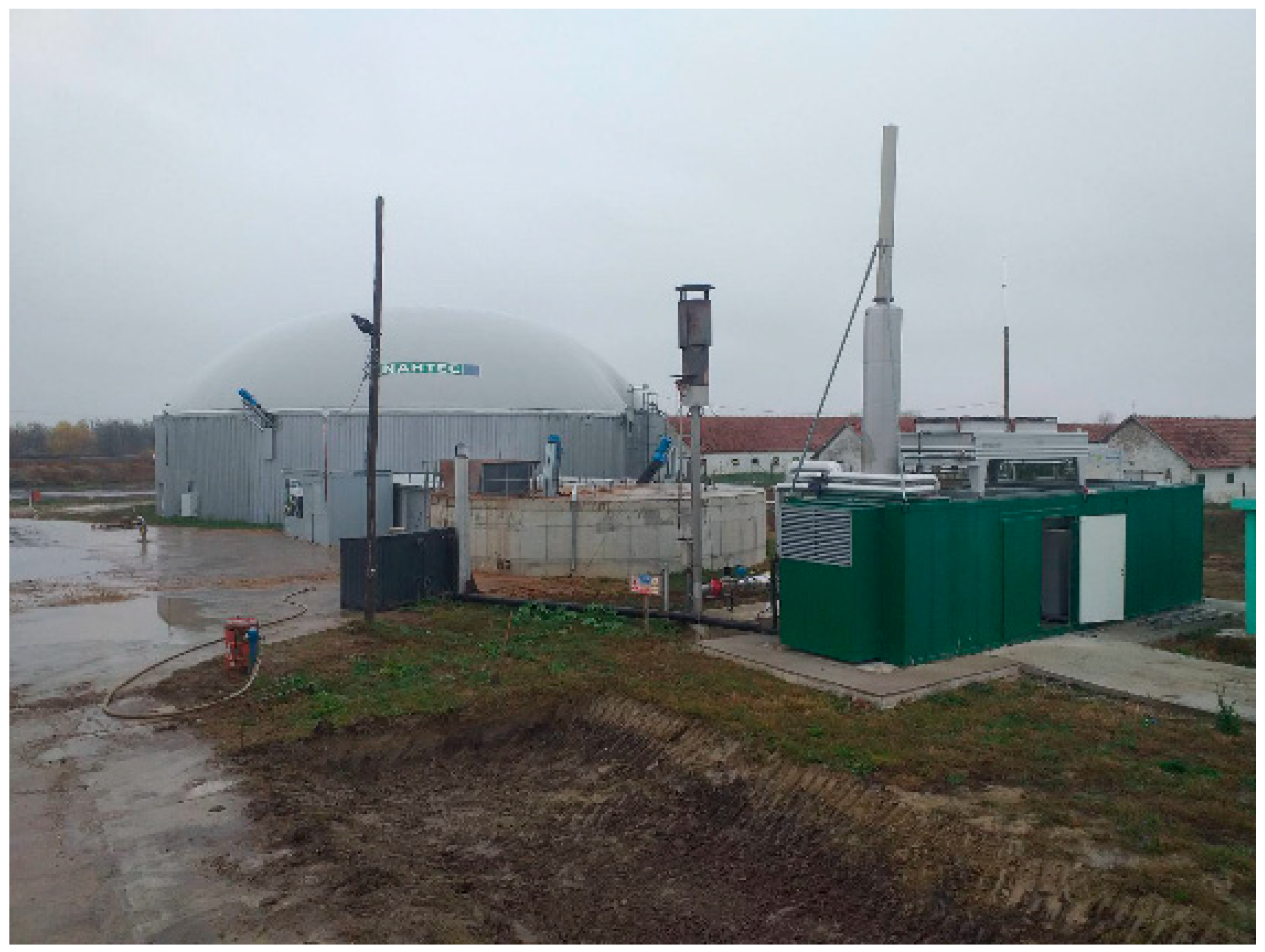
Biogas Plant Components
- Manure storage tank: a facility for storing raw manure before processing;
- Pumping station: used for transferring manure and other substrates to the digester;
- Condensate pit: collects and drains condensate formed during the biogas production process;
- Digester: the main unit where anaerobic digestion takes place;
- Lagoon: used for storing digested material (digestate) after the fermentation process;
- CHP unit (combined heat and power): generates electricity and heat from biogas;
- Separator: separates solid and liquid fractions of the digestate;
- Gas torch: burns excess biogas that cannot be used or stored;
- Blower: maintains the pressure of biogas within the system;
- Gas pipes: transport biogas from the digester to storage or the CHP unit;
- Fluid pipes: transport substrates and digestate between different units;
- Heaters: installed within the digester to maintain optimal temperature;
- Control unit: monitors and controls the entire biogas production process.
3. Results and Discussion
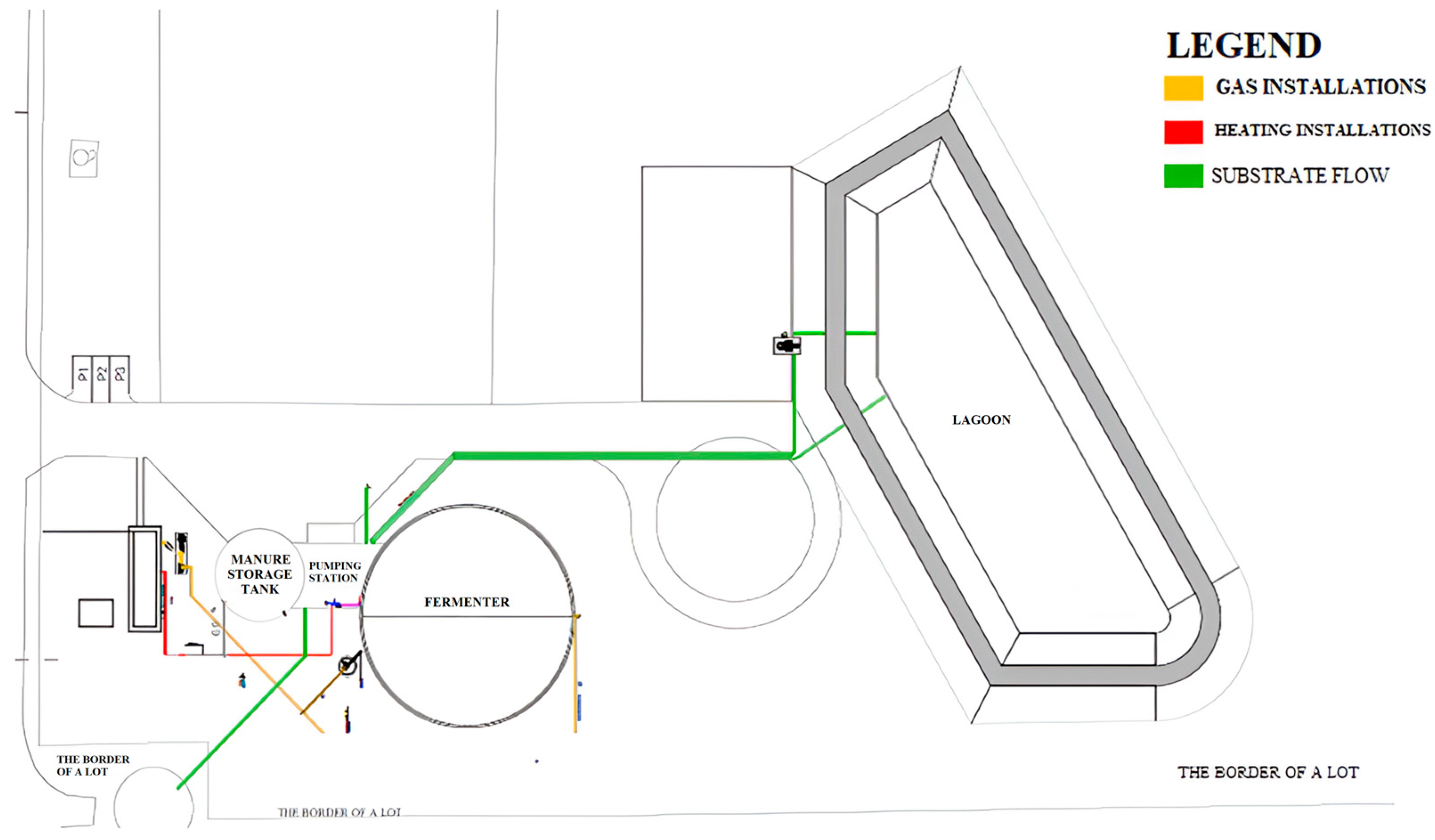
3.1. Substrate Flow
- Pumping a mixture of raw materials with a proportion of up to 11% dry matter, for dosing into a digester.
- PE100 DA225 mm PN10;
- DN200 V2A (204 × 2.0).
3.2. Biogas Flow
- Material: PEHD PE 100 DA 225 PN 6–GAS;
- Material: 1.4571 DN150 (154 × 2.0) and DN 200 (204 × 2.0).
3.3. The Flow of the System of the Heating
3.4. The Objects and the Equipment
3.4.1. The Mixing Hole
3.4.2. The Digester
3.4.3. The Pump Station with the Equipment
3.4.4. The Devices for Measuring
3.4.5. The Lagoon
3.4.6. The Storage of the Gas
3.4.7. The Valve for the Protection of the Storage on High Pressure and Low Pressure
3.4.8. The Gas Power Line and the Parts of the Gas Power Line
3.5. Digester Heating Technique
- Occurrence of heat loss through the digester mantle;
- Heat loss due to the dosing of the substrate at a lower temperature than expected.
4. Conclusions
Author Contributions
Funding
Institutional Review Board Statement
Informed Consent Statement
Data Availability Statement
Conflicts of Interest
References
- Obaideen, K.; Abdelkareem, M.A.; Wilberforce, T.; Elsaid, K.; Sayed, E.T.; Maghrabie, H.M.; Olabi, A.G. Biogas Role in Achievement of the Sustainable Development Goals: Evaluation, Challenges, and Guidelines. J. Taiwan Inst. Chem. Eng. 2022, 131, 104207. [Google Scholar] [CrossRef]
- Kabeyi, M.J.B.; Olanrewaju, O.A. Biogas Production and Applications in the Sustainable Energy Transition. J. Energy 2022, 2022, 1–43. [Google Scholar] [CrossRef]
- Fröschle, B.; Heiermann, M.; Lebuhn, M.; Messelhäusser, U.; Plöchl, M. Hygiene and Sanitation in Biogas Plants. In Biogas Science and Technology; Guebitz, G.M., Bauer, A., Bochmann, G., Gronauer, A., Weiss, S., Eds.; Advances in Biochemical Engineering/Biotechnology; Springer International Publishing: Cham, Switzerland, 2015; Volume 151, pp. 63–99. ISBN 978-3-319-21992-9. [Google Scholar]
- Molinuevo-Salces, B.; Fernández-Varela, R.; Uellendahl, H. Key Factors Influencing the Potential of Catch Crops for Methane Production. Environ. Technol. 2014, 35, 1685–1694. [Google Scholar] [CrossRef] [PubMed]
- Djordjevic, L.; Prvulovic, S.; Djurdjev, M.; Novakovic, B.; Bakator, M. Solar Technology: Empowering Serbia’s Renewable Energy Future. Mater. Tehnol. 2024, 58, 33–39. [Google Scholar] [CrossRef]
- Nayal, F.S.; Mammadov, A.; Ciliz, N. Environmental Assessment of Energy Generation from Agricultural and Farm Waste through Anaerobic Digestion. J. Environ. Manag. 2016, 184, 389–399. [Google Scholar] [CrossRef] [PubMed]
- Markou, G.; Brulé, M.; Balafoutis, A.; Kornaros, M.; Georgakakis, D.; Papadakis, G. Biogas Production from Energy Crops in Northern Greece: Economics of Electricity Generation Associated with Heat Recovery in a Greenhouse. Clean Technol. Environ. Policy 2017, 19, 1147–1167. [Google Scholar] [CrossRef]
- Milani, M.; Montorsi, L.; Stefani, M. An Integrated Approach to Energy Recovery from Biomass and Waste: Anaerobic Digestion–Gasification–Water Treatment. Waste Manag. Res. J. Sustain. Circ. Econ. 2014, 32, 614–625. [Google Scholar] [CrossRef] [PubMed]
- Methling, T.; Armbrust, N.; Haitz, T.; Speidel, M.; Poboss, N.; Braun-Unkhoff, M.; Dieter, H.; Kempter-Regel, B.; Kraaij, G.; Schliessmann, U.; et al. Power Generation Based on Biomass by Combined Fermentation and Gasification—A New Concept Derived from Experiments and Modelling. Bioresour. Technol. 2014, 169, 510–517. [Google Scholar] [CrossRef] [PubMed]
- Manganelli, B. Economic Feasibility of a Biogas Cogeneration Plant Fueled with Biogas from Animal Waste. Adv. Mater. Res. 2013, 864–867, 451–455. [Google Scholar] [CrossRef]
- Jameel, M.K.; Mustafa, M.A.; Ahmed, H.S.; Mohammed, A.J.; Ghazy, H.; Shakir, M.N.; Lawas, A.M.; Mohammed, S.K.; Idan, A.H.; Mahmoud, Z.H.; et al. Biogas: Production, Properties, Applications, Economic and Challenges: A Review. Results Chem. 2024, 7, 101549. [Google Scholar] [CrossRef]
- Singh, A.K.; Pal, P.; Rathore, S.S.; Sahoo, U.K.; Sarangi, P.K.; Prus, P.; Dziekański, P. Sustainable Utilization of Biowaste Resources for Biogas Production to Meet Rural Bioenergy Requirements. Energies 2023, 16, 5409. [Google Scholar] [CrossRef]
- Mignogna, D.; Ceci, P.; Cafaro, C.; Corazzi, G.; Avino, P. Production of Biogas and Biomethane as Renewable Energy Sources: A Review. Appl. Sci. 2023, 13, 10219. [Google Scholar] [CrossRef]
- Alhammad, B.A.; Seleiman, M.F. Improving Plant Growth, Seed Yield, and Quality of Faba Bean by Integration of Bio-Fertilizers with Biogas Digestate. Agronomy 2023, 13, 744. [Google Scholar] [CrossRef]
- Häring, G.; Sonnleitner, M.; Bär, K.; Brown, N.; Zörner, W. Demonstration of Controllable Electricity Production via Biogas Plants. Chem. Eng. Technol. 2017, 40, 298–305. [Google Scholar] [CrossRef]
- Rosén, T.; Ödlund, L. System Perspective on Biogas Use for Transport and Electricity Production. Energies 2019, 12, 4159. [Google Scholar] [CrossRef]
- Akbulut, A. Techno-Economic Analysis of Electricity and Heat Generation from Farm-Scale Biogas Plant: Çiçekdağı Case Study. Energy 2012, 44, 381–390. [Google Scholar] [CrossRef]
- Abusoglu, A.; Anvari-Moghaddam, A.; Guerrero, J.M. Producing Bio-Electricity and Bio-Heat from Urban Sewage Sludge in Turkey Using a Two-Stage Process. In Proceedings of the 2019 International Conference on Power Generation Systems and Renewable Energy Technologies (PGSRET), Istanbul, Turkey, 26–27 August 2019; IEEE: Istanbul, Turkey, 2019; pp. 1–4. [Google Scholar]
- Monteiro, E.; Mantha, V.; Rouboa, A. Prospective Application of Farm Cattle Manure for Bioenergy Production in Portugal. Renew. Energy 2011, 36, 627–631. [Google Scholar] [CrossRef]
- Karellas, S.; Boukis, I.; Kontopoulos, G. Development of an Investment Decision Tool for Biogas Production from Agricultural Waste. Renew. Sustain. Energy Rev. 2010, 14, 1273–1282. [Google Scholar] [CrossRef]
- Ali, S.; Yan, Q.; Razzaq, A.; Khan, I.; Irfan, M. Modeling Factors of Biogas Technology Adoption: A Roadmap towards Environmental Sustainability and Green Revolution. Environ. Sci. Pollut. Res. 2022, 30, 11838–11860. [Google Scholar] [CrossRef]
- Dölle, K.; Hughes, T.; Kurzmann, D.E. From Fossil Fuels to Renewable Biogas Production from Biomass Based Feedstock—A Review of Anaerobic Digester Systems. J. Energy Res. Rev. 2020, 1–37. [Google Scholar] [CrossRef]
- Mahmudul, H.M.; Akbar, D.; Rasul, M.G.; Narayanan, R.; Mofijur, M. Estimation of the Sustainable Production of Gaseous Biofuels, Generation of Electricity, and Reduction of Greenhouse Gas Emissions Using Food Waste in Anaerobic Digesters. Fuel 2022, 310, 122346. [Google Scholar] [CrossRef]
- Elmoutez, S.; Abushaban, A.; Necibi, M.C.; Sillanpää, M.; Liu, J.; Dhiba, D.; Chehbouni, A.; Taky, M. Design and Operational Aspects of Anaerobic Membrane Bioreactor for Efficient Wastewater Treatment and Biogas Production. Environ. Chall. 2023, 10, 100671. [Google Scholar] [CrossRef]
- Nsair, A.; Onen Cinar, S.; Alassali, A.; Abu Qdais, H.; Kuchta, K. Operational Parameters of Biogas Plants: A Review and Evaluation Study. Energies 2020, 13, 3761. [Google Scholar] [CrossRef]
- Glivin, G.; Kalaiselvan, N.; Mariappan, V.; Premalatha, M.; Murugan, P.C.; Sekhar, J. Conversion of Biowaste to Biogas: A Review of Current Status on Techno-Economic Challenges, Policies, Technologies and Mitigation to Environmental Impacts. Fuel 2021, 302, 121153. [Google Scholar] [CrossRef]
- Nwokolo, N.; Mukumba, P.; Obileke, K.; Enebe, M. Waste to Energy: A Focus on the Impact of Substrate Type in Biogas Production. Processes 2020, 8, 1224. [Google Scholar] [CrossRef]
- Belinska, S.; Bielik, P.; Adamičková, I.; Husárová, P.; Onyshko, S.; Belinska, Y. Assessment of Environmental and Economic-Financial Feasibility of Biogas Plants for Agricultural Waste Treatment. Sustainability 2024, 16, 2740. [Google Scholar] [CrossRef]
- Iqbal, M.W.; Kang, Y. Waste-to-Energy Supply Chain Management with Energy Feasibility Condition. J. Clean. Prod. 2021, 291, 125231. [Google Scholar] [CrossRef]
- Ellacuriaga, M.; García-Cascallana, J.; Gómez, X. Biogas Production from Organic Wastes: Integrating Concepts of Circular Economy. Fuels 2021, 2, 144–167. [Google Scholar] [CrossRef]
- Gontaruk, Y.; Kolomiiets, T.; Honcharuk, I.; Tokarchuk, D. Production and Use of Biogas and Biomethane from Waste for Climate Neutrality and Development of Green Economy. J. Ecol. Eng. 2024, 25, 20–32. [Google Scholar] [CrossRef]
- Kemfert, C.; Schäfer, D.; Semmler, W. Great Green Transition and Finance. Intereconomics 2020, 55, 181–186. [Google Scholar] [CrossRef]
- Djordjević, L.; Pekez, J.; Novaković, B.; Bakator, M.; Djurdjev, M.; Ćoćkalo, D.; Jovanović, S. Increasing Energy Efficiency of Buildings in Serbia—A Case of an Urban Neighborhood. Sustainability 2023, 15, 6300. [Google Scholar] [CrossRef]
- Batra, G. Renewable Energy Economics: Achieving Harmony between Environmental Protection and Economic Goals. Soc. Sci. Chron. 2023, 2, 1–32. [Google Scholar] [CrossRef]
- Nakashima, R.N. Modelling, Simulation and Optimization of Biogas Conversion Routes Integrated with Fuel Cell Technology. Ph.D. Thesis, Universidade de São Paulo, São Paulo, Brazil, 2022. [Google Scholar]
- Bandura, I.; Romaniuk, M.; Komenda, N.; Hadai, A.; Volynets, V. Optimisation of energy solutions: Alternative energy, reactive power compensation, and energy efficiency management. Mach. Energetics 2023, 14, 121–130. [Google Scholar] [CrossRef]
- Okafor, C.C.; Nzekwe, C.A.; Ajaero, C.C.; Ibekwe, J.C.; Otunomo, F.A. Biomass Utilization for Energy Production in Nigeria: A Review. Clean. Energy Syst. 2022, 3, 100043. [Google Scholar] [CrossRef]
- Andiavitri, D.L.; Wening, N.; Nur, S.M.; Kusrini, E. The Role of Bioenergy Resources in America’s Circular Bioeconomy. In Proceedings of the 6th International Seminar on Business, Economics, Social Science, and Technology (ISBEST), Tangerang Selatan, Indonesia, 20 September 2023; Volume 3. [Google Scholar] [CrossRef]
- Cinar, S.Ö.; Wieczorek, N.; Kosheleva, A.; Küçüker, M.A.; Kuchta, K. Biogas Production from Aquatic Biomass. In Algae and Aquatic Macrophytes in Cities; Elsevier: Amsterdam, The Netherlands, 2022; pp. 203–231. ISBN 978-0-12-824270-4. [Google Scholar]
- Hernández-Beltrán, J.U.; Hernández-De Lira, I.O.; Cruz-Santos, M.M.; Saucedo-Luevanos, A.; Hernández-Terán, F.; Balagurusamy, N. Insight into Pretreatment Methods of Lignocellulosic Biomass to Increase Biogas Yield: Current State, Challenges, and Opportunities. Appl. Sci. 2019, 9, 3721. [Google Scholar] [CrossRef]
- Tao, Y.; You, F. Consequential Life Cycle Assessment: Evaluating the Environmental Impact of Dairy Manure Treatment Using Thermochemical Conversion Technologies. In A-Z of Biorefinery; Elsevier: Amsterdam, The Netherlands, 2022; pp. 607–637. ISBN 978-0-12-819248-1. [Google Scholar]
- Imeni, S.M.; Puy, N.; Ovejero, J.; Busquets, A.M.; Bartroli, J.; Pelaz, L.; Ponsá, S.; Colón, J. Techno-Economic Assessment of Anaerobic Co-Digestion of Cattle Manure and Wheat Straw (Raw and Pre-Treated) at Small to Medium Dairy Cattle Farms. Waste Biomass Valorization 2020, 11, 4035–4051. [Google Scholar] [CrossRef]
- Zhang, S.; Xiao, M.; Liang, C.; Chui, C.; Wang, N.; Shi, J.; Liu, L. Multivariate Insights into Enhanced Biogas Production in Thermophilic Dry Anaerobic Co-Digestion of Food Waste with Kitchen Waste or Garden Waste: Process Properties, Microbial Communities and Metagenomic Analyses. Bioresour. Technol. 2022, 361, 127684. [Google Scholar] [CrossRef]
- Scholwin, F.; Nelles, M. Energy Flows in Biogas Plants: Analysis and Implications for Plant Design. In The Biogas Handbook; Elsevier: Amsterdam, The Netherlands, 2013; pp. 212–227. ISBN 978-0-85709-498-8. [Google Scholar]
- Lobato, L.C.S.; Chernicharo, C.A.L.; Pujatti, F.J.P.; Martins, O.M.; Melo, G.C.B.; Recio, A.A.R. Use of Biogas for Cogeneration of Heat and Electricity for Local Application: Performance Evaluation of an Engine Power Generator and a Sludge Thermal Dryer. Water Sci. Technol. 2013, 67, 159–167. [Google Scholar] [CrossRef] [PubMed]
- Stanojevic, M.; Simic, S.; Jovovic, A.; Radic, D.; Obradovic, M.; Todorovic, D. Biogas Production and Application; University of Belgrade, Faculty of Mechanical Engineering: Belgrade, Serbia, 2014; ISBN 978-86-7083-796-6. [Google Scholar]
- Panawis Plus. Available online: https://biogas.org.rs/project/panawis-plus-doo/ (accessed on 10 December 2023).
- HOST. Available online: https://www.host.nl/sr/biogasna-postrojenja/poljoprivredna-biogasna-postrojenja/ (accessed on 5 May 2024).
- Lantz, M. The Economic Performance of Combined Heat and Power from Biogas Produced from Manure in Sweden—A Comparison of Different CHP Technologies. Appl. Energy 2012, 98, 502–511. [Google Scholar] [CrossRef]
- Prvulović, S.; Tolmac, J.; Joksimović, M.; Dragičević, D. Biogas Equipment for Electricity and Heating. Sci. Tech. Rev. 2020, 70, 17–20. [Google Scholar] [CrossRef]
- Prvulovic, S.; Josimovic, M.; Radosav, D.; Tolmac, J.; Jovanovic, S.; Micic, I. Determining the Thermal Energy Required to Heat a Biogas Plant Fermenter. Mater. Tehnol. 2022, 56, 11–17. [Google Scholar] [CrossRef]
- Prvulović, S.; Tolmac, J.; Desnica, E.; Josimović, M.; Bicok, I. The Station for Dosing the Substratum into Existing Digesters: PreMix. Sci. Tech. Rev. 2021, 71, 15–18. [Google Scholar] [CrossRef]
- Kaparaju, P.; Rintala, J. Generation of Heat and Power from Biogas for Stationary Applications: Boilers, Gas Engines and Turbines, Combined Heat and Power (CHP) Plants and Fuel Cells. In The Biogas Handbook; Elsevier: Amsterdam, The Netherlands, 2013; pp. 404–427. ISBN 978-0-85709-498-8. [Google Scholar]

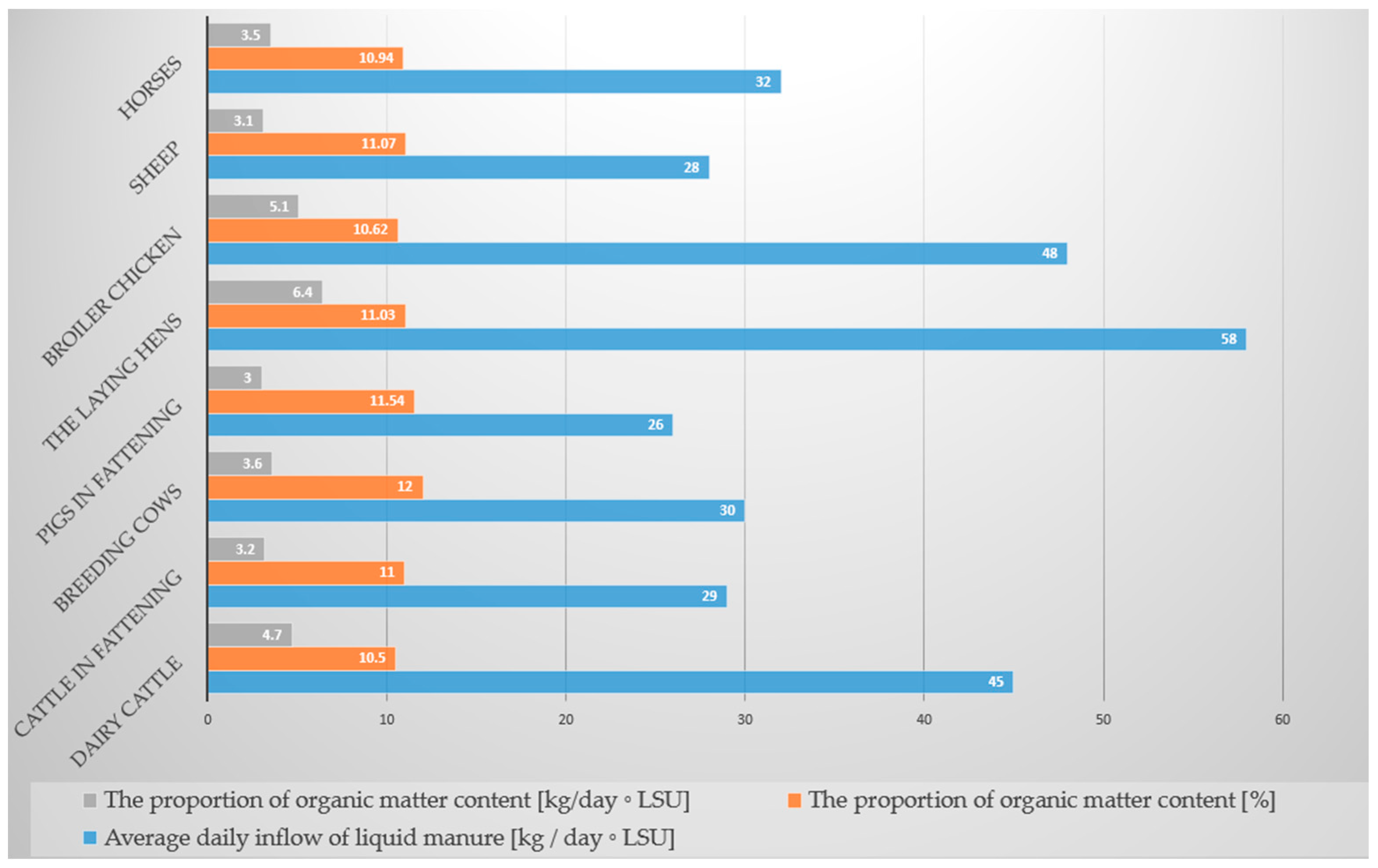
| A Species of Domestic Animal | Average Daily Inflow of Liquid Manure at Average Organic Matter Content by Weight of 11% | The Proportion of Organic Matter Content in the Liquid Manure (gomc) | The Proportion of Organic Matter Content in the Liquid Manure (gomc) | Average Nitrogen Content in Organic Matter Content | C:N Ratio in Organic Matter Content | Average Biogas Yield) | Average Biogas Yield |
|---|---|---|---|---|---|---|---|
| [kg/day × LSU] | [%] | [kg/day × LSU] | [%] | [m3/(kgorganic mattercontent × day)] | [ƒbg(kgorganic mattercontent × day)] | ||
| Dairy cattle | 45 | 10.5 | 4.7 | 1.7 ÷ 6.0 | (17 ÷ 25):1 | 0.18 ÷ 0.33 | 0.846 ÷ 1.551 |
| Cattle in fattening | 29 | 11 | 3.2 | 1.7 ÷ 6.0 | (17 ÷ 25):1 | 0.16 ÷ 0.32 | 0.512 ÷ 1.024 |
| Breeding cows | 30 | 12 | 3.6 | 3.8 | (6 ÷ 12):1 | 0.34 ÷ 0.55 | 1.224 ÷ 1.980 |
| Pigs in fattening | 26 | 11.54 | 3 | 3.8 | (6 ÷ 12.5):1 | 0.30 ÷ 0.55 | 0.900 ÷ 1.650 |
| The laying hens | 58 | 11.03 | 6.4 | 6.0 ÷ 6.5 | (7 ÷ 15):1 | 0.31 ÷ 0.62 | 1.984 ÷ 3.968 |
| Broiler chicken | 48 | 10.62 | 5.1 | 6.3 | 15:1 | 0.30 ÷ 0.56 | 1.530 ÷ 2.856 |
| Sheep | 28 | 11.07 | 3.1 | 3.8 | 33:1 | 0.09 ÷ 0.31 | 0.279 ÷ 0.961 |
| Horses | 32 | 10.94 | 3.5 | 2.3 | 25:1 | 0.20 ÷ 0.30 | 0.700 ÷ 1.051 |
| The Internal Membrane | |
|---|---|
| Material | PELD |
| Thickness | 0.8 mm |
| Weight | 750 g/m2 |
| Tautness/firmness | 650 N/cm |
| Surface resistance | ˂3 × 10⁹ Ohm |
| The resistance of leaking | ˂3 × 10⁹ Ohm |
| The permeability of the gas (methane) | 260 cm3/m2 × d × 1 bar |
| The resistance to the temperature | −30 °C ± 70 °C |
| The Outer Membrane | |
| Material | double PVC—covered with polyester cloth |
| Weight | 670 g/m2 |
| Tautness/firmness | 3000 N/cm |
| Surface resistance | ˂3 × 10⁹ Ohm |
| The resistance of leaking | ˂3 × 10⁸ Ohm |
| The permeability of the gas (methane) | 260 cm3/m2 × d × 1 bar |
| The resistance to the temperature | −30 °C ± 70 °C |
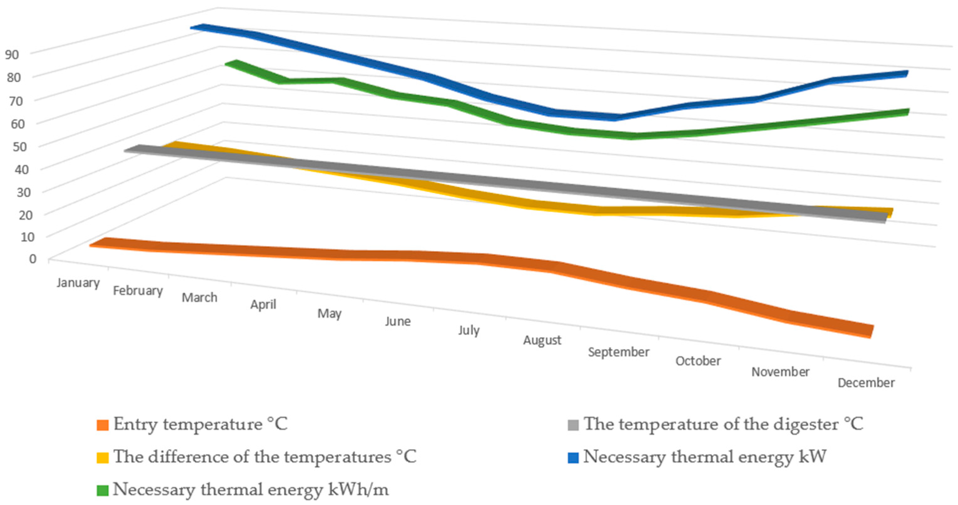
| Month | d/m | Entry Temperature | The Temperature of the Digester | The Difference of the Temperatures | Necessary Thermal Energy | Necessary Thermal Energy |
|---|---|---|---|---|---|---|
| °C | °C | °C | kW | kWh/m | ||
| January | 31 | 5.0 | 40.5 | 35.5 | 87.5 | 65.097 |
| February | 28 | 6.0 | 40.5 | 34.5 | 85.0 | 57.141 |
| March | 31 | 8.0 | 40.5 | 32.5 | 80.1 | 59.596 |
| April | 30 | 10.0 | 40.5 | 30.5 | 75.2 | 54.124 |
| May | 31 | 12.0 | 40.5 | 28.5 | 70.2 | 52.261 |
| June | 30 | 15.0 | 40.5 | 25.5 | 62.8 | 45.251 |
| July | 31 | 17.0 | 40.5 | 23.5 | 57.9 | 43.092 |
| August | 31 | 17.0 | 40.5 | 23.5 | 57.9 | 43.092 |
| September | 30 | 14.0 | 40.5 | 26.5 | 65.3 | 47.026 |
| October | 31 | 12.0 | 40.5 | 28.5 | 70.2 | 52.261 |
| November | 30 | 8.0 | 40.5 | 32.5 | 80.1 | 57.673 |
| December | 31 | 6.0 | 40.5 | 34.5 | 85.0 | 63.263 |
| Sum | 877.2 | 639.878 | ||||
| Average | 73.1 | 53.323 | ||||
| Maximum | 87.5 | 65.097 | ||||
| Minimum | 57.9 | 43.092 | ||||
Disclaimer/Publisher’s Note: The statements, opinions and data contained in all publications are solely those of the individual author(s) and contributor(s) and not of MDPI and/or the editor(s). MDPI and/or the editor(s) disclaim responsibility for any injury to people or property resulting from any ideas, methods, instructions or products referred to in the content. |
© 2024 by the authors. Licensee MDPI, Basel, Switzerland. This article is an open access article distributed under the terms and conditions of the Creative Commons Attribution (CC BY) license (https://creativecommons.org/licenses/by/4.0/).
Share and Cite
Josimović, L.; Prvulović, S.; Djordjević, L.; Bicok, I.; Bakator, M.; Premčevski, V.; Šarenac, U.; Šeljmeši, D. Enhancing Biogas Plant Efficiency for the Production of Electrical and Thermal Energy. Appl. Sci. 2024, 14, 5858. https://doi.org/10.3390/app14135858
Josimović L, Prvulović S, Djordjević L, Bicok I, Bakator M, Premčevski V, Šarenac U, Šeljmeši D. Enhancing Biogas Plant Efficiency for the Production of Electrical and Thermal Energy. Applied Sciences. 2024; 14(13):5858. https://doi.org/10.3390/app14135858
Chicago/Turabian StyleJosimović, Ljubisa, Slavica Prvulović, Luka Djordjević, Ivana Bicok, Mihalj Bakator, Velibor Premčevski, Uroš Šarenac, and Dalibor Šeljmeši. 2024. "Enhancing Biogas Plant Efficiency for the Production of Electrical and Thermal Energy" Applied Sciences 14, no. 13: 5858. https://doi.org/10.3390/app14135858
APA StyleJosimović, L., Prvulović, S., Djordjević, L., Bicok, I., Bakator, M., Premčevski, V., Šarenac, U., & Šeljmeši, D. (2024). Enhancing Biogas Plant Efficiency for the Production of Electrical and Thermal Energy. Applied Sciences, 14(13), 5858. https://doi.org/10.3390/app14135858