Article

Heat Transfer Performance and Operation Scheme of the Deeply Buried Pipe Energy Pile Group

1
School of Civil Engineering and Environment, Hubei University of Technology, Wuhan 430068, China
2
China Academy of Building Research, Beijing 100013, China
*
Author to whom correspondence should be addressed.
Appl. Sci. 2024, 14(13), 5928; https://doi.org/10.3390/app14135928
Submission received: 3 May 2024 / Revised: 27 June 2024 / Accepted: 3 July 2024 / Published: 7 July 2024
(This article belongs to the Section Applied Thermal Engineering)

Abstract

:
This paper describes a study on the heat transfer properties of the deeply buried pipeline energy pile group, which is an efficient and convenient geothermal development technology. Through in situ experiments and a simulation algorithm, the research investigated the heat transmission characteristics of the deeply buried pipe energy pile group and optimized different intermittent operation schemes. The findings suggest that prolonged operation of the pile cluster intensifies heat buildup within the pile foundation, thereby adversely affecting the system’s overall heat exchange efficiency. Employing an intermittent operating mode can alleviate this heat accumulation phenomenon, thereby promoting sustained heat exchange performance of the piles over time. To evaluate the comprehensive thermal interaction and energy efficiency ratio of the energy pile heat exchange system, various intermittent operation strategies were compared in the study. Among them, the intermittent operational scheme with a ratio of n = 5 was found to be optimal, with the total average heat transfer rate of the pile set only 0.51% lower than that of the continuous operational mode, but the overall energy efficiency ratio improved by 19.6%. The intermittent operational mode proposed in this study can achieve the goal of saving energy and efficiently extracting geothermal resources, providing theoretical guidance for the extraction and utilization of subsurface geothermal power by energy piles.

1. Introduction

Shallow geothermal is a renewable and clean energy source [1,2,3], and shallow geothermal storage is one of the technologies used to store and extract stored geothermal energy when needed [4]. At present, there are two kinds of underground structures for collecting and developing shallow geothermal energy: (1) Ground source heat pumps (GSHP); (2) Energy pile. Shallow geo-thermal energy demonstrates a high energy conversion rate, which is facilitated by the heat exchange between the heat carrier fluid in the underground heat exchange tube and the adjacent soil [5].
In previous studies, there was considerable research on the heat transfer efficiency of GSHP [6,7,8,9,10,11,12,13,14] and inside-buried pipe energy piles [15], mainly including structural heat transfer characteristics, heat transfer simulation analysis methods, and geotechnical thermal properties [16,17]. However, there has been less analysis on the optimization of the heat exchange system during the operational phase [18,19,20,21]. Melis [22] and others taking into account both the cooling and heating demands of the structure along with the intermittent operational mode of the GSHP, assessed the system performance of the energy pile through numerical simulation., and used the service life assessment model for comparison of the environmental performance differences between the two heat exchange systems. By studying the thermal effects of intermittent operational mode and continuous operational mode on energy piles, Li et al. [23] observed that in the operational mode of 16 h operation and 8 h stop, the axial strain and stress of piles were relatively stable, and the displacement of pile end and pile bottom did not change significantly. Cao et al. [24] studied the effect of phase-change backfill materials on the thermal performance of precast high-strength concrete energy piles under intermittent operational mode, and found that the heat transfer efficiency of phase-change backfill material energy piles under intermittent operational mode was more affected than that of ordinary grout energy piles. Gui [25] and others developed a three-dimensional numerical simulation model to analyze heat transfer within a configuration involving multiple piles. The investigation focused on assessing the heating performance of the system under both continuous and intermittent operating conditions. The outcomes indicate that the energy pile exhibits superior long-term heat transfer performance during intermittent operation compared to continuous operation. Jahangir [26] and colleagues investigated how intermittent operation affects the thermal storage capabilities of GSHP. Their findings suggest a progressive decline in the system’s thermal storage capacity with the escalation of operating cycles. Liang [27] and others conducted a numerical simulation of the heat transfer and flow characteristics of a single helical coil buried tube heat exchanger over a week, considering the coupled heat and moisture migration of backfill and soil, and found that intermittent operation can improve the thermal performance of the buried tube heat exchanger. Yang [28] and others proposed an intermittent operation strategy for a composite GSHP system, designed the system based on actual engineering, formulated four operating conditions, and studied them through simulation. The findings demonstrated that implementing the intermittent operation strategy notably decreased soil thermal accumulation and effectively attained the optimal intermittent operating state. The aforementioned studies primarily concentrated on the analysis of heat exchange in single pile configurations. Enhancing the operational strategies of heat exchange structures can significantly enhance heat transfer efficiency and decrease operational energy consumption.
GSHP and energy piles are often deployed in groups, making the study of heat exchanger arrays particularly important. Behbehani [29] and others investigated the long-term hydrothermal response and the thermal storage performance related to unsaturated soil energy pile groups during high-temperature injection periods. Upon comparing with conventional buried tube heat exchangers, it was observed that the heat extraction efficiency of the pile group increased by approximately 1.2 times. They also established a heat transfer model for pile groups, and simulation results indicated that the enhanced energy pile groups had higher heat transfer capabilities than ordinary groups, while the thermal impact area around the piles increased. Utilizing the heat transfer characteristics of GSHP as a foundation, Xu [30] and others, constructed a comprehensive physical model for a 3U pile foundation heat exchanger group, subsequently conducting simulations to analyze the heat transfer processes involved. The findings indicated that the thermal conductivity of the pile foundation heat exchangers surpassed that of the surrounding soil, resulting in enhanced heat transfer efficiency. Additionally, it was noted that the heat flux per meter of the pile foundation heat exchanger displayed a gradual decrease throughout the study period.
Contemporary investigations into subterranean energy infrastructures predominantly center on GSHP and on energy inside-buried pipe energy piles [31,32,33,34,35,36], with less emphasis on the deeply buried pipe energy pile (DBP-EP) [14,15,16]. The structural construction of DBP-EP differs from that of the inside-buried pipe energy piles. Through the installation of a borehole heat exchanger (BHE) within the pile foundation, penetrating to depths of hundreds of meters, the heat exchange capacity of the pile structure is amplified, thereby augmenting the overall heat exchange capability [15,37]. While there is considerable analysis on the heat transfer between piles and soil for groups of DBP-EP, there is yet no analysis on the intermittent operation of systems predominantly using DBP-EP.
This paper focused on DBP-EP as the subject of study. By conducting on-site in situ experiments, we evaluated the heat transfer characteristics during operation, through numerical models for the individual and the DBP-EP group, comparing different operational schemes. Our study delved into the impact of intermittent operational modes on the heat transfer dynamics of the DBP-EP group. We propose meticulously devised operational strategies aimed at optimizing efficiency while minimizing energy consumption. Furthermore, our findings offer valuable theoretical insights into the extraction and utilization of shallow geothermal resources from energy piles.

2. Summary of Field Test and Analysis of Results

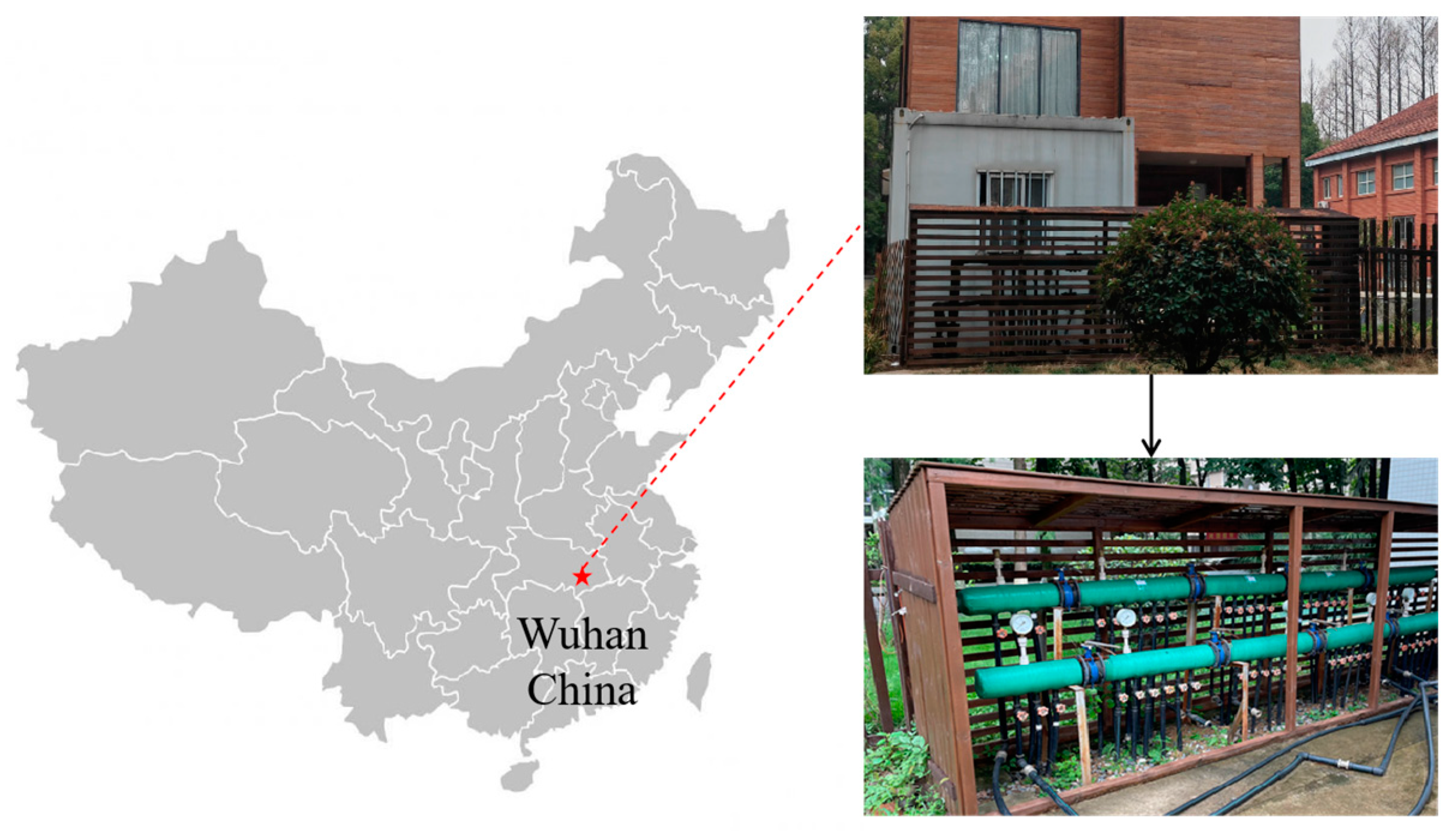
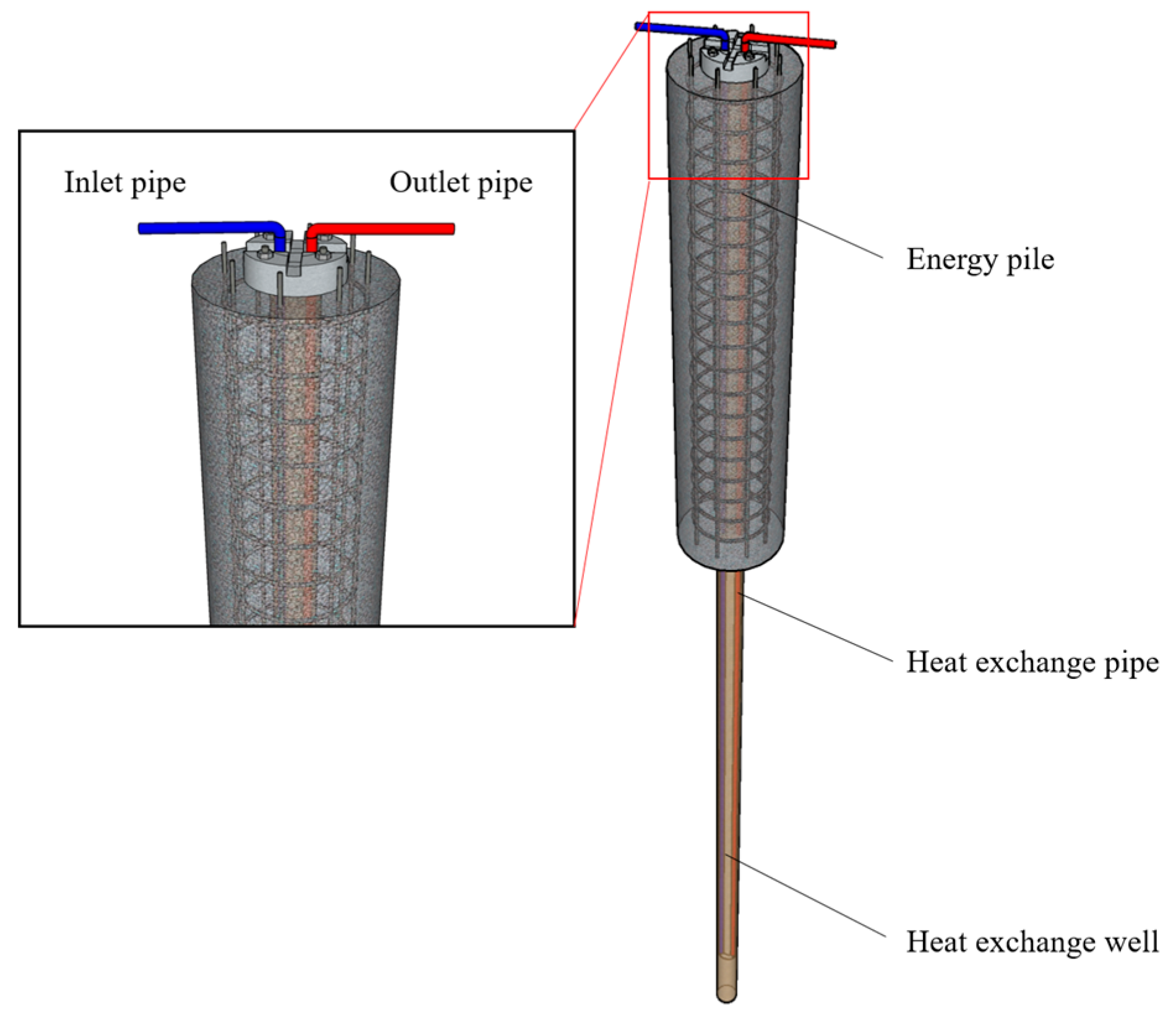
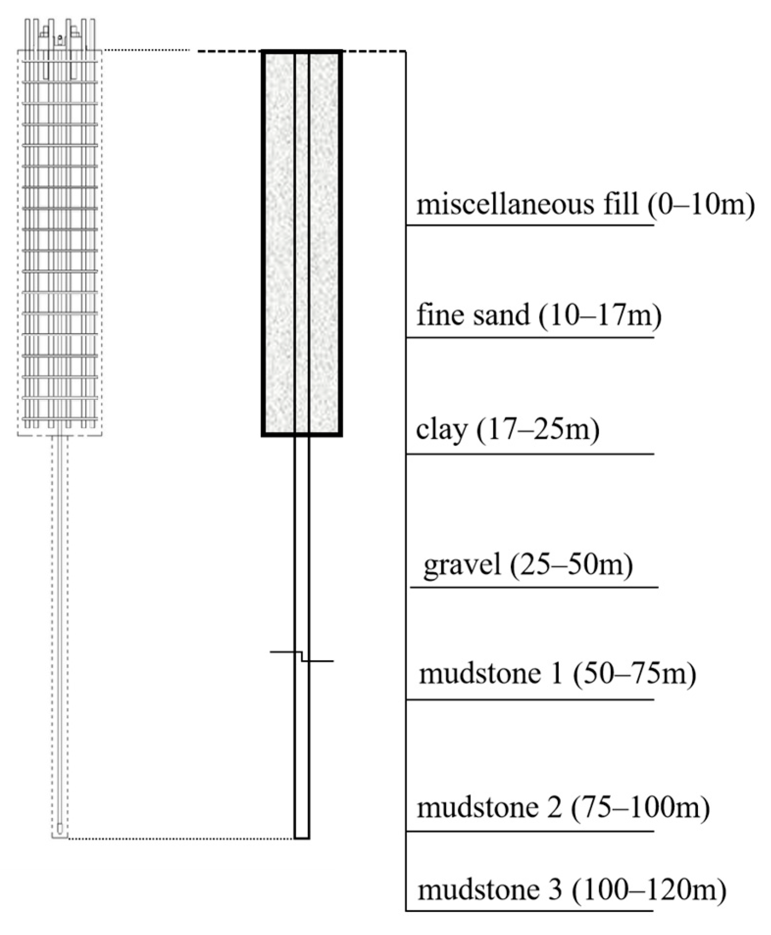
2.1. Site Overview and Test Scheme

Experiments were conducted at the energy pile testing base [37] and the experimental site is situated in Hubei University of Technology, where DBP-EPs had a caliber of 800 mm and a length of 23 m. The piles were constructed as drilled and cast-in-place, with a concrete strength grade of C30. The BHE was a 100 m deep borehole drilled in the pile center, with a well caliber of 150 mm and a depth of 100 m, backfilled with fine sand. Heat exchange pipes and temperature sensors were embedded on the reinforcement cage and connected through control pipelines to a manifold. The heat exchange piping was set up in a double U-shape arrangement with the piping running parallel to each piece. The pipe had an external caliber of 25 mm and an internal caliber of 20 mm. Figure 1 shows the location of the test site. Figure 2 shows the overall structure diagram of the energy pile.
The field test data of the DBP-EP test base were used to verify the accuracy of the simulation [38]. Figure 3 shows the stratigraphic distribution. The site is mainly composed of a fine sand layer, clay layer, gravel layer, and mudstone layer. The experimentation took place in the summer season, characterized by an average ambient temperature of 28 °C, focusing on a DBP-EP specimen. This experiment used a thermal response tester to heat the heat carrier fluid in the pipeline. A water pumping system was employed to regulate the fluid flow rate within the conduits. Prior to conducting the experiment, the initial temperature of the geological layers was documented as 18.5 °C employing a distributed fiber optic temperature sensing system (DTS). A 48 h thermal response test followed. A heat carrier fluid was circulated within an underground tube heat exchanger at a flow rate of 1 m3/h and an initial temperature of 30 °C. Following heating, the heat carrier fluid was directed into the heat exchanger to facilitate the heat exchange process. During the experiment, the temperatures at the entry and exportation of the DBP-EP, as well as the heat carrier fluid (composed of water) flow rate, were recorded.

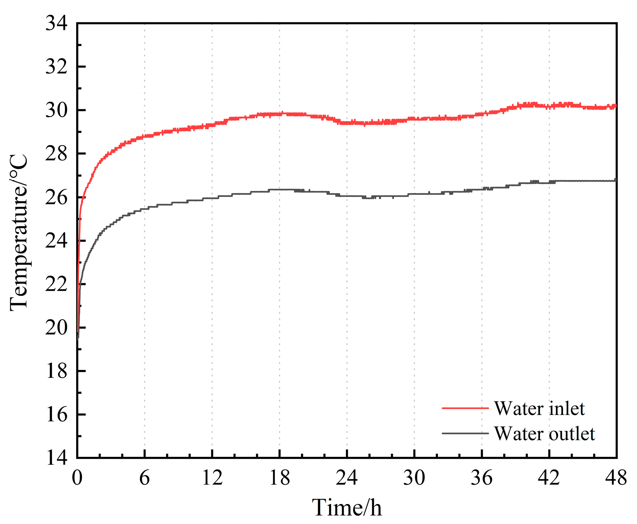
2.2. Field Test Analysis

Figure 4 illustrates the temperature change curves at the entry and exportation of the DBP-EP. Initially, the temperatures at these points showed a gradual increase followed by stabilization. This phenomenon occurs because during the initial stages of the heat exchange operation, the heat pump unit consistently warms the circulating medium at the inlet to achieve the desired inlet water temperature for testing purposes. Consequently, the temperature differential between the entry and exportation increases rapidly, resulting in a steep rise in temperature.
As the experiment progressed, the rate of temperature increase at both the entry and exportation of the heat exchange tube gradually diminished and approached stability. Ultimately, the temperature difference settled at approximately 3.4 °C. This stabilization occurs as the heat exchange equilibrium between the pile body and the surrounding rock and soil gradually establishes over time.

3. Numerical Simulations: Thermal Behavior of DBP-EP

3.1. Technical Features of the Used Software

3.1.1. Governing Equations Set in COMSOL

The setting of the geothermal gradient is based on the related literature of shallow geothermal [30]. Initiating with a surface temperature of 17 °C, the temperature increment of 3 °C per 100 m descent from the surface was employed to emulate a more authentic formation temperature. The formation temperature function (T0) is articulated as follows:
T g = T 0 + 0.03 z
In the equation: T0 indicates the initial thermal condition, set at 17 °C; z indicates the depth span of the domain.
In the process of model construction, non-isothermal flow is used to control the heat exchanger channel and circulating water flow, and the two are regarded as one-dimensional states, which simplifies the heat transfer operation. The control equation is as follows:
ρ u t = t ρ · e t 1 2 f D ρ d h u u + F · e t
In the formula: ρ represents fluid density; u represents the average cross-sectional velocity; f D represents the Darcy friction factor; F represents the volumetric force density; d h is the average hydraulic diameter.
The heat exchange efficiency of DBP-EP s is intricately tied to the temperature variance between the entry and exportation of the heat exchange pipes. The mathematical representation is provided as follows:
Q = ν ρ c p t
In the formula: Q denotes the rate of heat exchange, in watts (W); ν denotes the volumetric flow rate of the heat carrier fluid, in cubic meters per hour (m3/h); ρ stands for the density of the heat carrier fluid, in kilograms per cubic meter (kg/m3); c p denotes the specific heat capacity of the heat transfer medium, in joules per kilogram-degree Celsius (J/(kg·°C)); t indicates the temperature differential between the entry and exportation water temperatures of the pile, in degrees Celsius (°C).
The energy efficiency ratio (EER) is chosen as the metric to evaluate the heat exchange efficiency:
EER = Q P
P = ν h g 102 n
In the formula: P represents the power of the heat pump system, in kilograms per hour (kg/h); h is the head of the water pump; g is the gravitational acceleration; n is the efficiency of the heat pump system, which in this study is set at 0.9.

3.1.2. Boundary Condition

Referencing experimental data from DBP-EP, the geometric parameters of the model are set at 10 m × 10 m × 120 m. The stratum material from top to bottom is set as a fill layer (0–10 m); a fine sand layer (10–17 m); a clay layer (17–25 m); a gravel layer (25–50 m); and a mudstone layer (50–120 m). Horizontal boundaries are positioned beneath the model surface at depths of 50 m, 75 m, and 100 m to delineate distinct mudstone layers, designated as mudstone layers 1, 2, and 3. Table 1 shows the physical parameters of formation materials. These layers are characterized by sequentially decreasing porosities of 0.25, 0.20, and 0.15, aiming to replicate the gradual compaction of actual stratigraphic formations with increasing depth. To enhance the fidelity of domain temperature simulation, an initial surface temperature of 17 °C is prescribed. With every meter descent from the surface, the temperature rises by 0.03 °C. Concurrently, the inlet water temperature is held constant at 30 °C. Due to the complex geological composition, to avoid interference from other factors on the pile’s heat transfer behavior, the foundation of the modeling of the DBP-EP rests upon the following subsequent presumptions:
The assumption of soil homogeneity is made; the thermophysical parameters of each layer of rock and soil are isotropic and remain unchanged, with no consideration given to the influence of internally generated steam on heat migration or the effects of thermal radiation within the soil on the thermal transfer processes of DBP-EPs.
The material used to backfill the pile is in complete contact with the surfaces of the heat exchange pipes, ensuring uniform thermal conductivity throughout the surrounding rock and soil layers. Any contact thermal resistance is considered negligible, and the system is assumed to conduct heat purely.
The potential impact of groundwater seepage on the heat exchange process of the pile was not accounted for in this analysis.
To facilitate enhancement precision of subsequent heat transfer computations concerning the pile, a refinement of the mesh was implemented at the interface connecting the heat exchange pipes and the DBP-EP. Tetrahedral meshes were chosen to partition the model, resulting in 236,228 boundary elements within the model. This mesh configuration remained unaltered throughout subsequent calculations. Figure 5 illustrates the mesh division model of the DBP-EP.

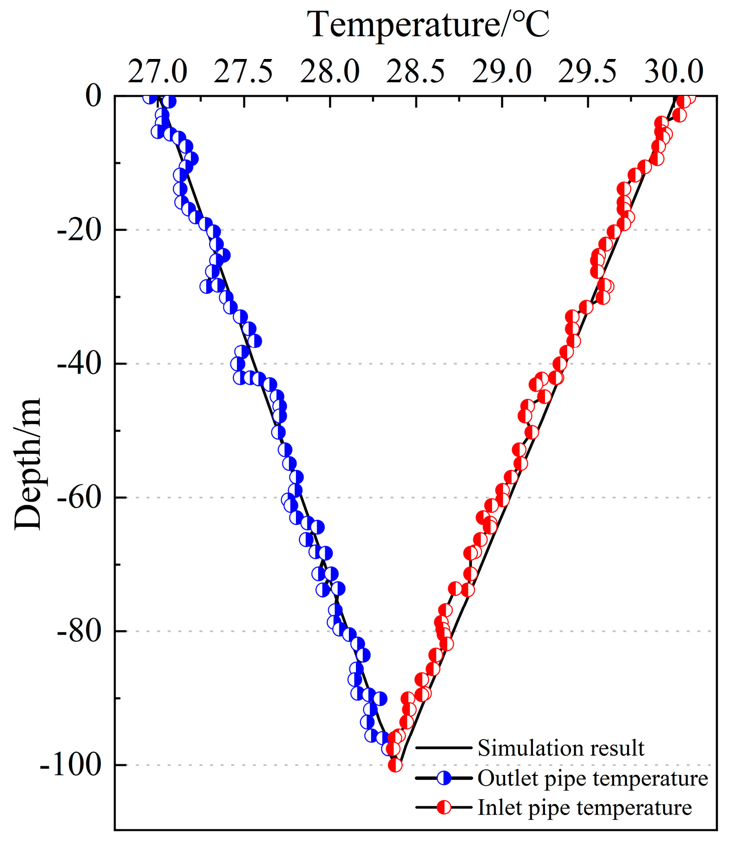
3.1.3. Model Verification

To validate the model’s accuracy, we utilized COMSOL 6.0 software to construct a simulation model for the heat exchange process within DBP-EPs. This model was developed based on the aforementioned data and involved creating an energy pile model with identical dimensions. Throughout the model setup phase, the solid heat transfer module was employed to configure appropriate heat transfer parameters for both the soil and the pile.
Non-isothermal pipe flow was designated to define the water flow characteristics within the heat exchange pipes. The inlet temperature of the heat transfer medium was adjusted based on experimental parameters, while maintaining a constant water flow rate of 1 m3/h through the pipes. Figure 6 illustrates the temperature variations of the heat carrier fluid within the pipes and the measured temperatures at various depths of the pile after 48 h of model operation.
The observed temperature fluctuations within the heat exchange pipes correlate closely with the measured data, demonstrating consistency across varying depths. The calculated root mean square deviation between experimental and simulated values stands at 0.148, indicative of a high level of agreement. Thus, the model exhibits robust reliability, bolstering its credibility for further analysis.

4. Results and Discussions

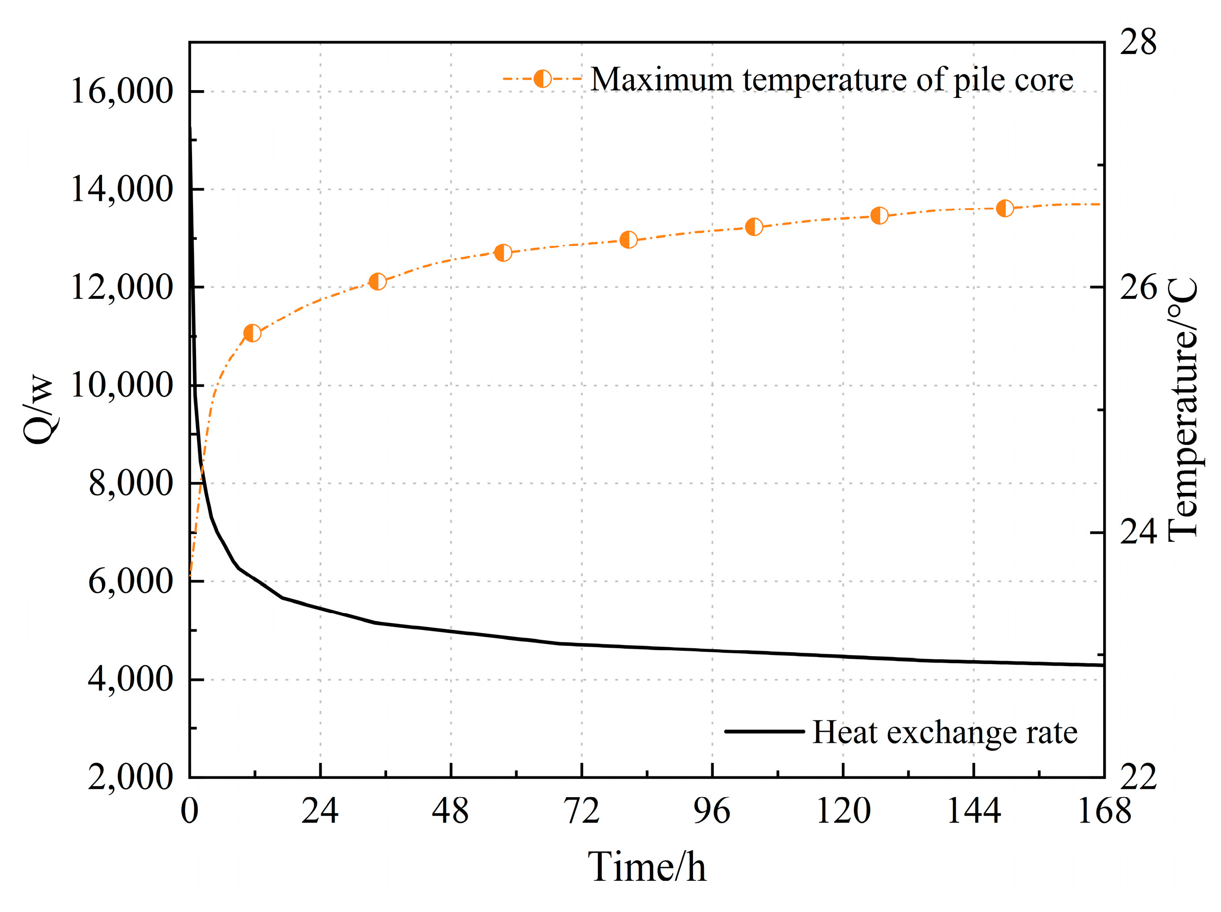
4.1. Heat Exchange Rate and Core Temperature Change of Single Pile

Figure 7 illustrates the temporal evolution of both the peak core temperature and the heat exchange rate of the DBP-EP throughout the operational period. From the graphical representation, it is evident that the heat exchange rate of the DBP-EP exhibits a gradual decline over the course of the operation, with the rate of decrease diminishing as the operation time extends. From 0 h to 12 h, the decrease in the pile’s heat exchange rate is the most significant, with a variation exceeding 59%. From 12 h to 168 h, the decline in the pile’s heat exchange rate gradually slows down and tends toward a stable state. At the onset of heat exchange operations, a notable temperature gradient exists between the pile and the surrounding soil and stones, which diminishes gradually over time. The peak core temperature of the DBP-EP shows an overall upward trend, and its variation stabilizes as the heat exchange operation of the pile continues. During the initial phases of thermal exchange, the peak core temperature rises rapidly, with the greatest increase occurring from the start of operation to 48 h, exceeding 44.4%, and then the peak core temperature curve gradually rises slowly and stabilizes. The continuous rise in core temperature exacerbates the degree of thermal accumulation inside the pile. When considering the trend in heat exchange efficiency, it becomes apparent that elevated core temperatures within the DBP-EP correspond to a gradual reduction in heat exchange rates. Consequently, the persistent elevation of the internal temperature within the pile foundation detrimentally impacts the overall heat exchange performance of the system.

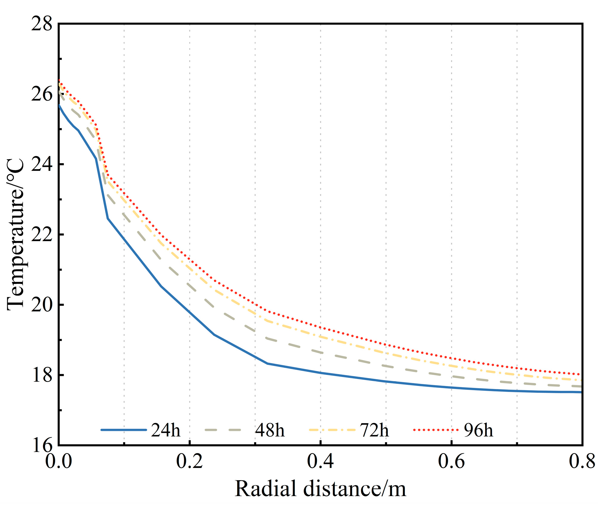
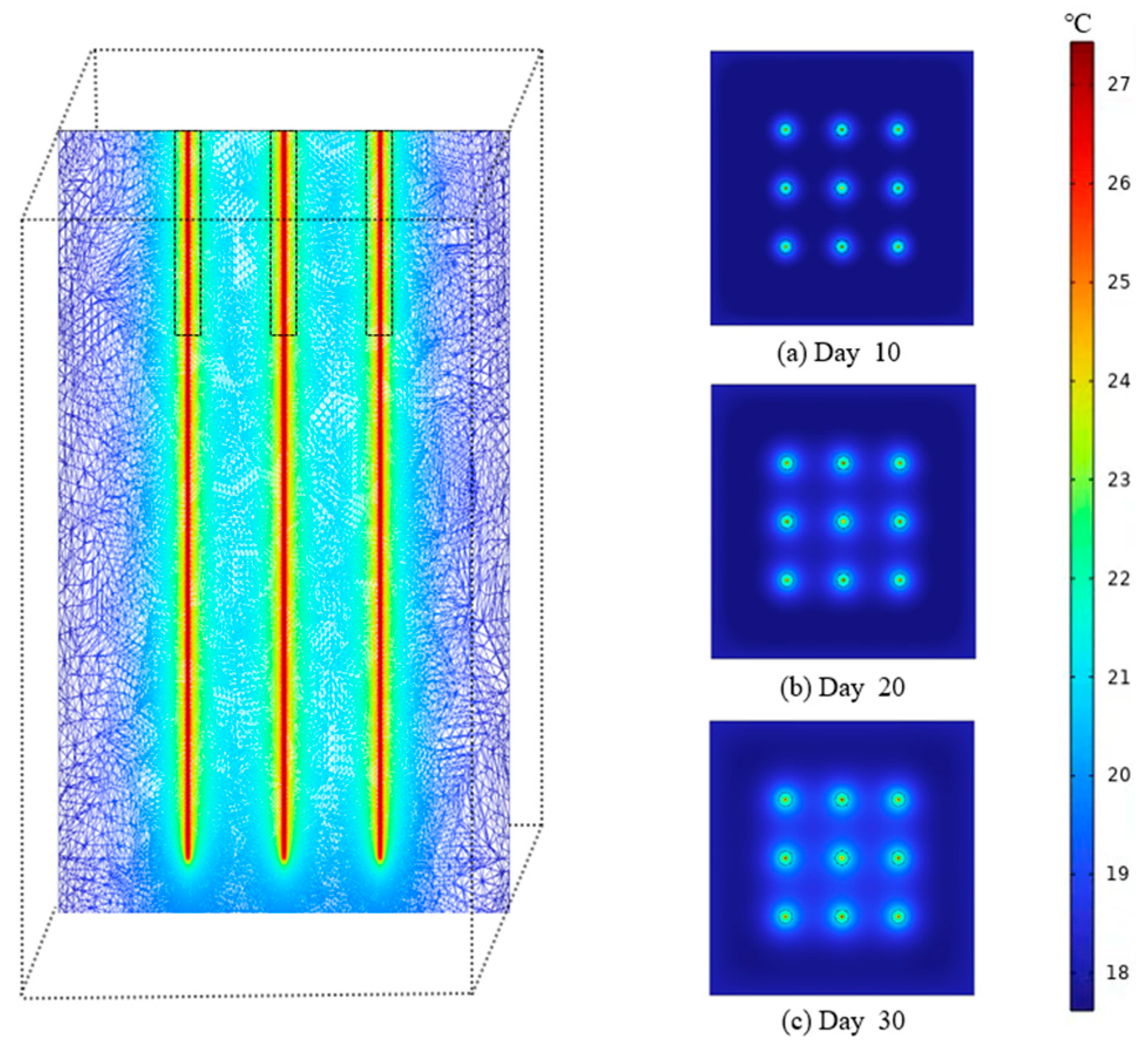
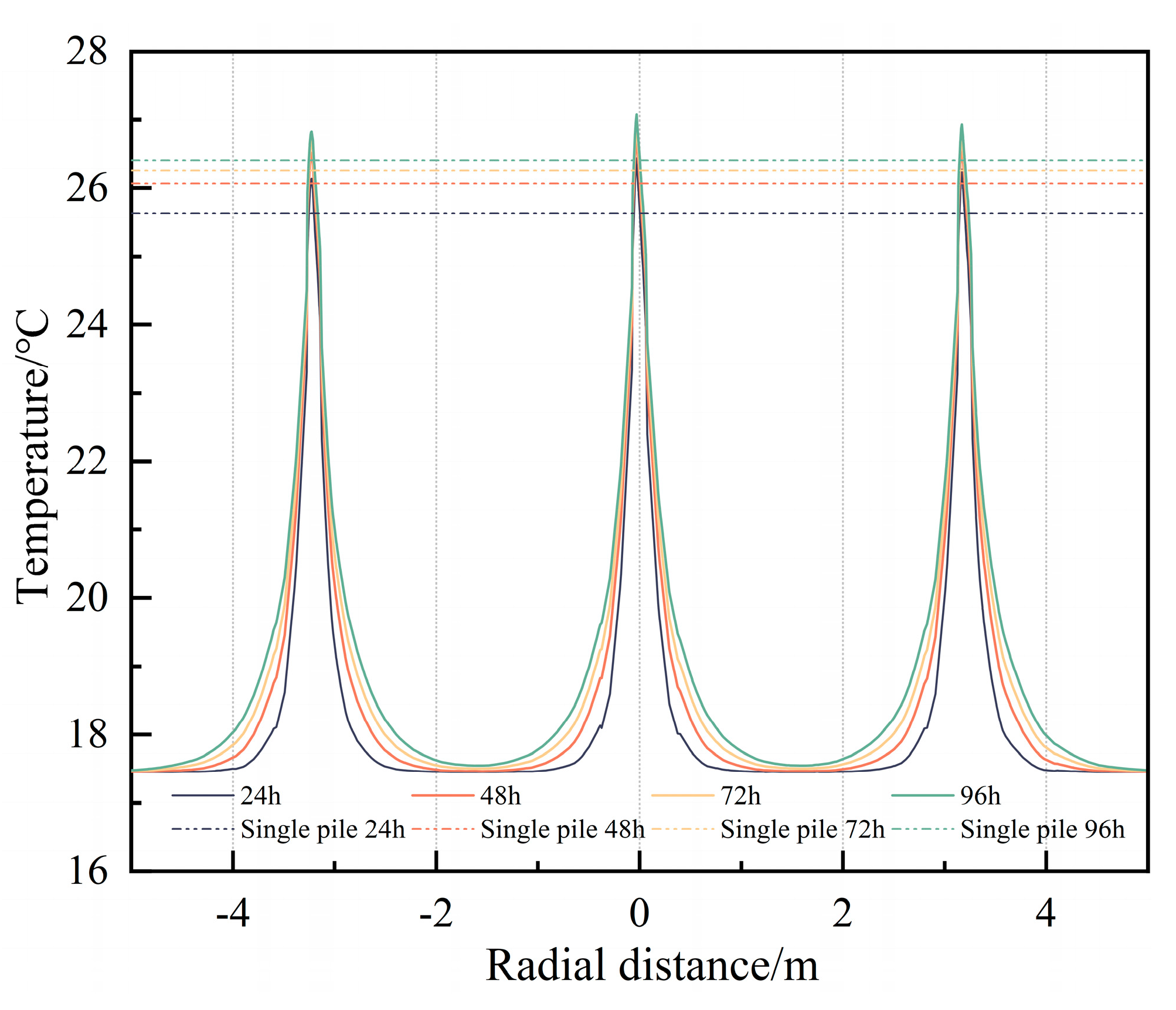
4.2. Single Pile Thermal Radius Change

Figure 8 shows the change curves of the thermal radius of DBP-EP at different time points under continuous operational mode (the thermal radius display range extends horizontally by 0.8 m from the pile center at 20 m depth of the pile). The four curves represent the thermal radius distribution of the pile at 24 h, 48 h, 72 h, and 96 h, respectively. The graphical representation illustrates that the diffusion range of the pile’s thermal radius gradually increases with the progression of the heat exchange operation of the pile foundation, and the rate of increase gradually diminishes. At 24 h, the core temperature of the pile is 25.68 °C, meanwhile the temperature at the pile wall is 18.06 °C, with a thermal gradient of 7.62 °C between the core and the wall. At a radial distance of 0.8 m, the temperature difference with the pile wall is 0.54 °C. At this point, internal heat begins to accumulate in the pile foundation and diffuses to the circumambient soil and stone. As a result of the abbreviated operational duration, the heat diffused into the soil is relatively less. By 96 h, the core temperature of the pile is 26.40 °C, the temperature at the pile wall is 19.35 °C, with a temperature difference of 7.05 °C between them. At a radial distance of 0.8 m, the temperature difference with the pile wall is 1.31 °C. As the core and wall temperatures rise, their temperature difference gradually decreases with the progression of the heat exchange operation, while the temperature change magnitude of the circumambient stone and soil increasingly magnify with operation time. Therefore, during the continuous interchange of heat process of DBP-EP, the degree of internal heat accumulation within the pile foundation is more severe compared to the circumambient soil and stone. Thus, the heat transfer performance of the pile can be diminished by continuous operational modes, making it essential to examine how intermittent operational modes influence the thermal conductivity efficiency of deep-buried tubular energy piles.

4.3. Heat Transfer of DBP-EP Group in Different Operation Schemes

In the actual project, energy piles often exist in groups, necessitating the establishment of a group pile heat exchange model to study the thermal characteristics of the ground as well as the thermal interference between piles, in order to understand at which distance to put each borehole. During the model setup, nine piles are arranged in a square grid, sequentially named from 1# to 9#, as shown in Figure 9. The distance between each pile is 3.2 m. The simulated domain dimensions are set to 15 m × 15 m × 120 m. The free tetrahedral mesh is used to optimize the connection position of heat exchange deep well and pile foundation, and other model settings remain the same as previously described.

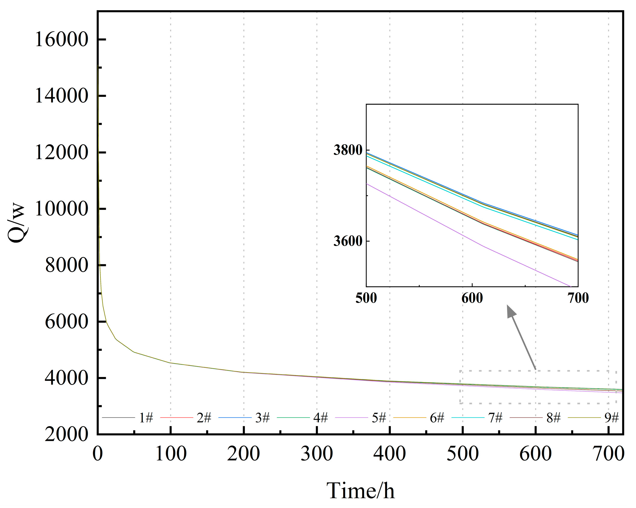
4.3.1. Continuous Heat Transfer Characteristics of Pile Group

Figure 10 shows the transverse temperature gradient cloud map at a depth of 20 m of the deep-buried pipeline energy pile group within 30 days of operation (Figure 10a–c represent the tenth, twentieth, and thirtieth days of heat exchange, respectively). As shown in the diagram, the internal temperature of the piles gradually increases with the heat exchange operation, and the thermal influence area of each individual pile gradually expands. In the thermal exchange procedure of the group piles until the tenth day, the thermal diffusion area of the individual piles is small, and there is no thermal interaction phenomenon between the piles. When the piles have been in operation for 30 days, the thermal diffusion area of the individual piles increases, and there is thermal interaction between the piles, indicating a more obvious thermal accumulation phenomenon in the group piles. The rationale behind this phenomenon lies in the high thermal conductivity of the concrete utilized in the pile foundation, facilitating continuous heat absorption from the thermal carrier fluid. Nevertheless, the heat conductivity coefficient of the adjacent rock and soil is significantly inferior to that of the concrete composing the pile foundation, so the heat inside the pile foundation cannot dissipate in time. Simultaneously, there is a common heat transfer zone between the group piles, which exacerbates the thermal accumulation inside the pile foundation and the circumambient soil and stone. To illustrate visually the adverse influence of the group pile effect regarding the thermal interchange process of DBP-EPs, Figure 10 displays the temporal evolution of the temperature differential between the entry and exportation water of the central pile within the grouped piles compared to that of a single pile.
Figure 11 depicts the temperature gradient between the entry and exportation heat carrier fluid of the central pile (i.e., pile 5#) and the single pile after 720 h of heat exchange. From the figure, it is evident that during the initial phase of thermal exchange, the most significant reduction in temperature differential between the entry and exportation of the two piles occurs. At this time, the differential in thermal transfer between the two piles is not significant. As the heat exchange operation progresses, the temperature contrast between the two stacks gradually stabilizes over time. After 300 h of heat exchange, the temperature contrast between the entry and exportation of pile 5# intensifies in comparison to the standalone pile. From 0 h to 168 h, the temperature difference between the entry and exportation of pile 5# is basically consistent with that of the single pile. At 720 h, the temperature differential between the entry and exportation of the single pile is 0.20 °C higher than that of pile 5#. Combined with Figure 10, it can be seen that the negative impact of the group pile effect formed under continuous operation gradually becomes significant regarding the thermal performance of the energy piles.
Figure 12 depicts the radial temperature profile at a depth of −20 m for pile configuration 4#, 5#, and 6#, as well as the highest temperature at the pile center for the single pile at 24, 48, 72, and 96 h. The temperature at the core of piles 4#, 5#, and 6# exhibits a gradual rise, accompanied by an expansion in the region of heat diffusion. The temperature at the center of pile 5# and the temperature of the circumambient soil and stone are higher than those of the peripheral piles. This is because the heat diffused by the peripheral piles is transferred to the central part of the soil and stone, thereby reducing the temperature difference between the circumambient soil and stone and the central pile, which negatively affects the subsequent heat exchange of pile 5#. The maximum temperature recorded at the core of the individual pile after 24, 48, 72, and 96 h is observed to be less than that of the group pile. At 96 h, the highest temperature at the center of the single pile is 0.66 °C lower than that of pile 5#, and on average, it is 0.57 °C lower than the temperature of the peripheral piles. This suggests that the adverse effects of continuous operational mode on the heat exchange efficiency of the central piles within the clustered pile system surpass those observed in the peripheral piles.

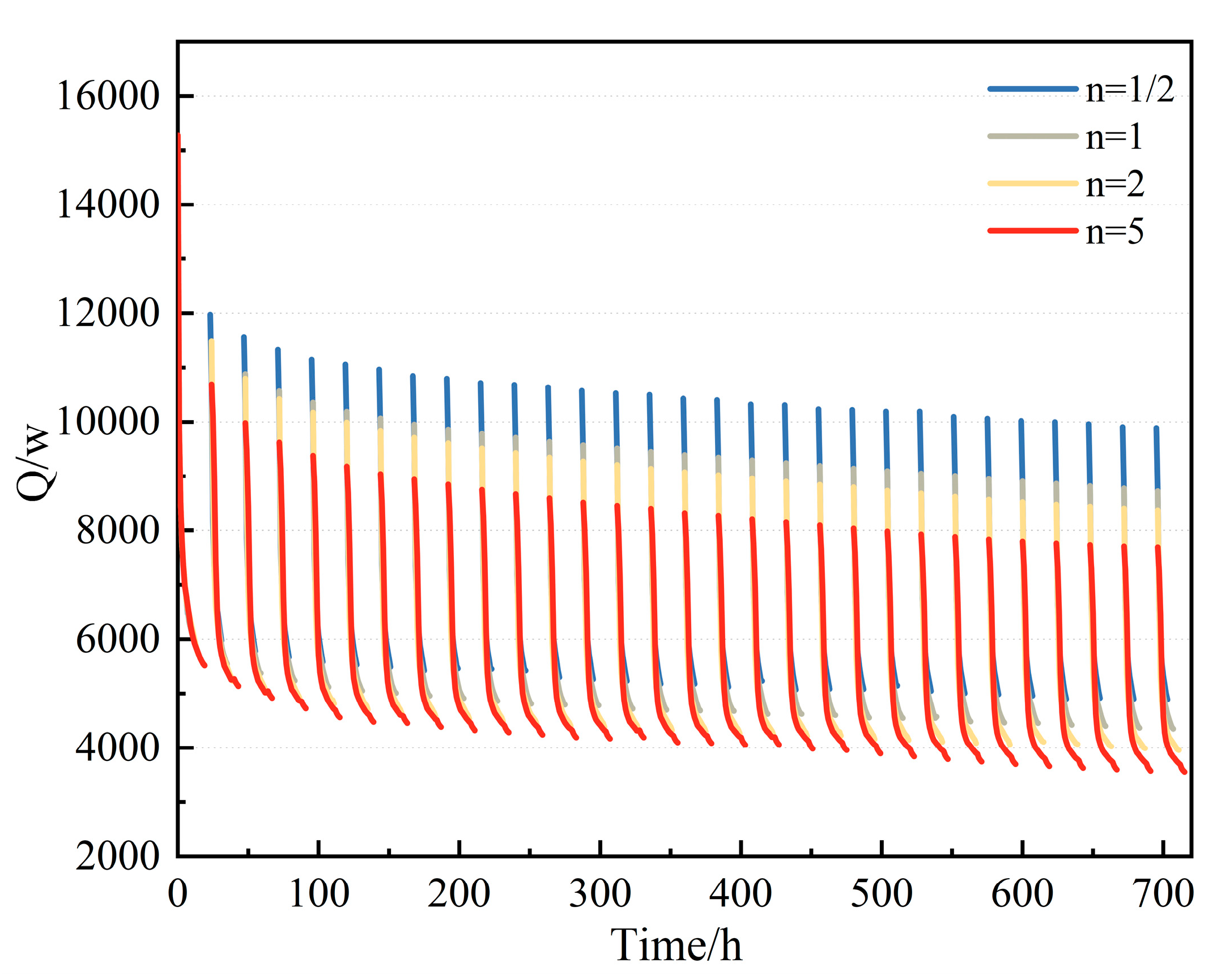
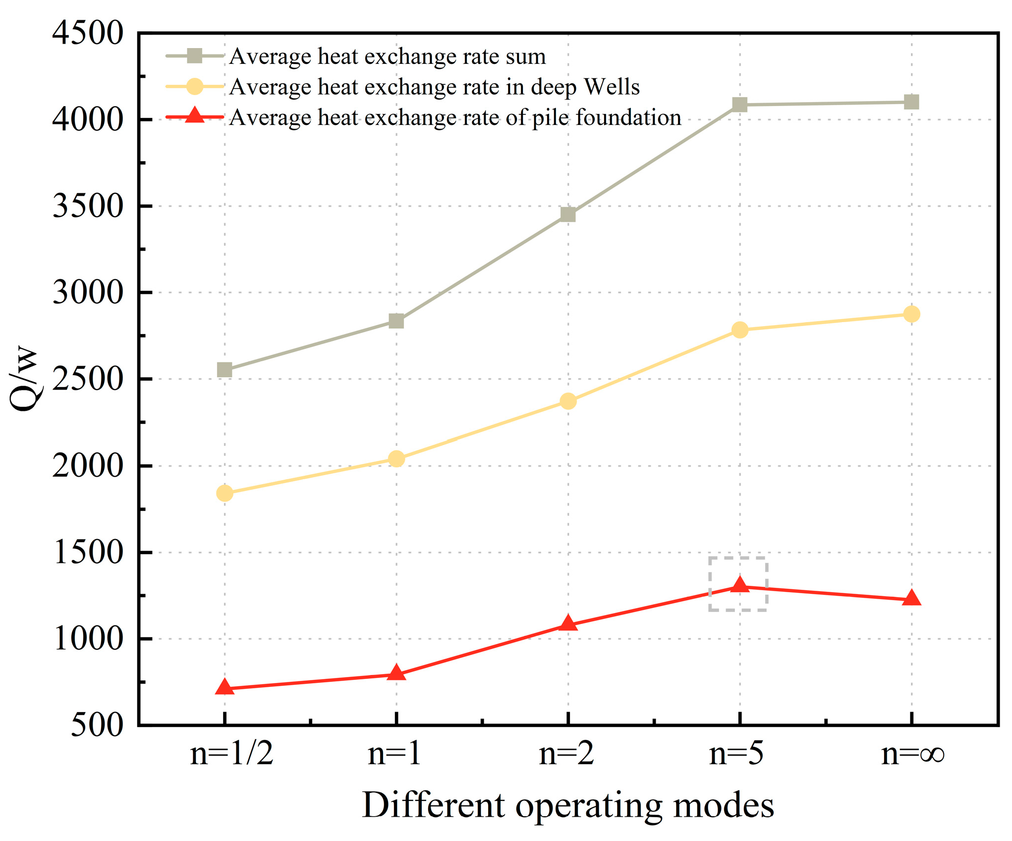
4.3.2. Comparison and Analysis of Rate of Thermal Exchange in Continuous and Intermittent Operational Mode

To facilitate intermittent operation among the clustered piles of DBP-EP, enhancements were made to the preceding model by implementing a piecewise function to regulate the rate of thermal energy transfer medium within the heat exchange conduit. During periods of heat exchange within the pile, the fluid velocity in the heat transfer process within the conduit is maintained at 1 m3/h, while during inactive phases of the pile, the velocity of the fluid involved in the heat transfer process within the conduit is reduced to 0 m3/h. Combining with the actual operation state of the piles, four intermittent operational modes were set as follows: ① 8 h on cycle, 16 h off; ② 12 h on cycle, 12 h off; ③ 16 h on cycle, 8 h off; ④ 20 h on cycle, 4 h off. The intermittent ratios (n, the ratio of the duration of pile operation to the duration of rest) for the four operational modes are n = 1/2, n = 1, n = 2, n = 5, and the intermittent ratio for the continuous operational mode is set as n = ∞. The duration of operation for these conditions is 30 days.
Figure 13 illustrates the fluctuation in thermal exchange rate pertaining to the group DBP-EP piles, running in continuous operational mode for 720 h. The depicted figure reveals a consistent downward trend in the thermal exchange rate curves across various positions of the piles. Before 50 h of heat exchange operation, there were no substantial variations observed in the thermal characteristics among the piles. However, as the heat exchange operation progressed to 500 h, the differences in heat exchange rates among the piles gradually increased, with pile 5# having a lower heat exchange rate than the other piles. When comparing piles 6# and 5#, notable differences emerge: at the 600 h mark, the heat exchange rate of pile 6# surpasses that of pile 5# by 52.2 W, while at 700 h, this margin expands to 66.90 W. This observation underscores an amplification in the disparity of heat exchange rates between the central pile and its counterparts with prolonged operational duration.
Figure 14 illustrates the temporal variations in heat transfer rate of pile 5# across distinct intermittent operational scenarios. As depicted in the graphical representation, the reduction in the heat exchange efficiency of pile 5# escalates as the intermittent ratio n increases, reaching its minimum when the intermittent ratio n = 5. This is because in the intermittent operational mode, the intermittent ratio n = 5 is lower than the temperature recovery degree of the circumambient stone with n = 2, 1, and 1/2, resulting in a decrease in the heat exchange rate of the pile in the subsequent heat exchange process.
Table 2 illustrates the mean heat exchange rates of the DBP-EP group across varied operational conditions over a 30-day period. Comparative analysis reveals that the average heat exchange rates of the DBP-EP exhibit an upward trend with increasing intermittent ratio (n), when contrasted with the continuous operational mode. The average heat exchange rates (sum) are less than those of the continuous operational mode when the intermittent ratio n is small, specifically 14,145.38 W, 11,572.98 W, 5975.33 W, and 190.80 W. The trend indicates a convergence of the mean rates of heat exchange of the pile group towards the continuous operational mode as the intermittent ratio (n) escalates. Moreover, the disparity in heat exchange performance between the two operational modes diminishes with higher values of the intermittent ratio (n). At an intermittent ratio of n = 5, the aggregate average heat exchange rate of the pile group closely approximates that of the continuous operational mode. Despite a heightened instantaneous heat exchange rate of the DBP-EP at lower intermittent ratios, the overall duration of the heat exchange operation for the pile is abbreviated, consequently yielding a substantial variance in the average heat exchange rate relative to the continuous operational mode. Therefore, in practical engineering, operating conditions should be selected reasonably according to the requirements.
By analyzing the temperature differential between the entry and exportation at the base of the 5# pile, we computed the mean heat exchange rate of the DBP-EP, subsequently contrasting it with the average heat exchange rate of the entire pile, as illustrated in Figure 15. On contrasting the thermal exchange outcomes of pile 5# between intermittent ratio n = 5 and continuous operational modes, observably, the mean heat exchange rates of pile 5# under both operational modes exhibit a minimal discrepancy, with only a 16.38 W differential. The thermal exchange curve of the deep well exhibits a progressive incline as the intermittent ratio n rises, with the rate of escalation gradually tapering off. Under intermittent operation at n = 5, the heat exchange rate of the deep well deviates by merely 91.47 W from that observed during continuous operation. Comparing the average heat exchange rates of the pile base under different operational modes, it can be seen that when n = 5, the average heat exchange rate of the DBP-EP base is the highest, exceeding that of the continuous operational mode by 75.10 W. Therefore, when the intermittent ratio is n = 5, the mean heat exchange rate of the pile base is optimal, and this intermittent operational mode can more effectively harness the elevated thermal conductivity inherent in the concrete foundation of the pile.
In conclusion, compared to continuous operational mode, the intermittent operational mode demonstrates effective reduction of the thermal accumulation inside the pile, thereby increasing the instantaneous heat exchange capacity in the course of the operational duration of the pile foundation. When the intermittent ratio is n = 5, the setting of the deep well can better enhance the heat dissipation effect of the thermal carrier fluid within the system of heat exchange pipe, thereby improving the heat exchange performance of the pile foundation. Henceforth, the installation of borehole heat exchangers (BHEs) at the base of the pile foundation serves a dual purpose: harnessing the thermal diffusivity of the concrete at the pile base and augmenting the long-term efficacy of heat exchange within the energy pile.

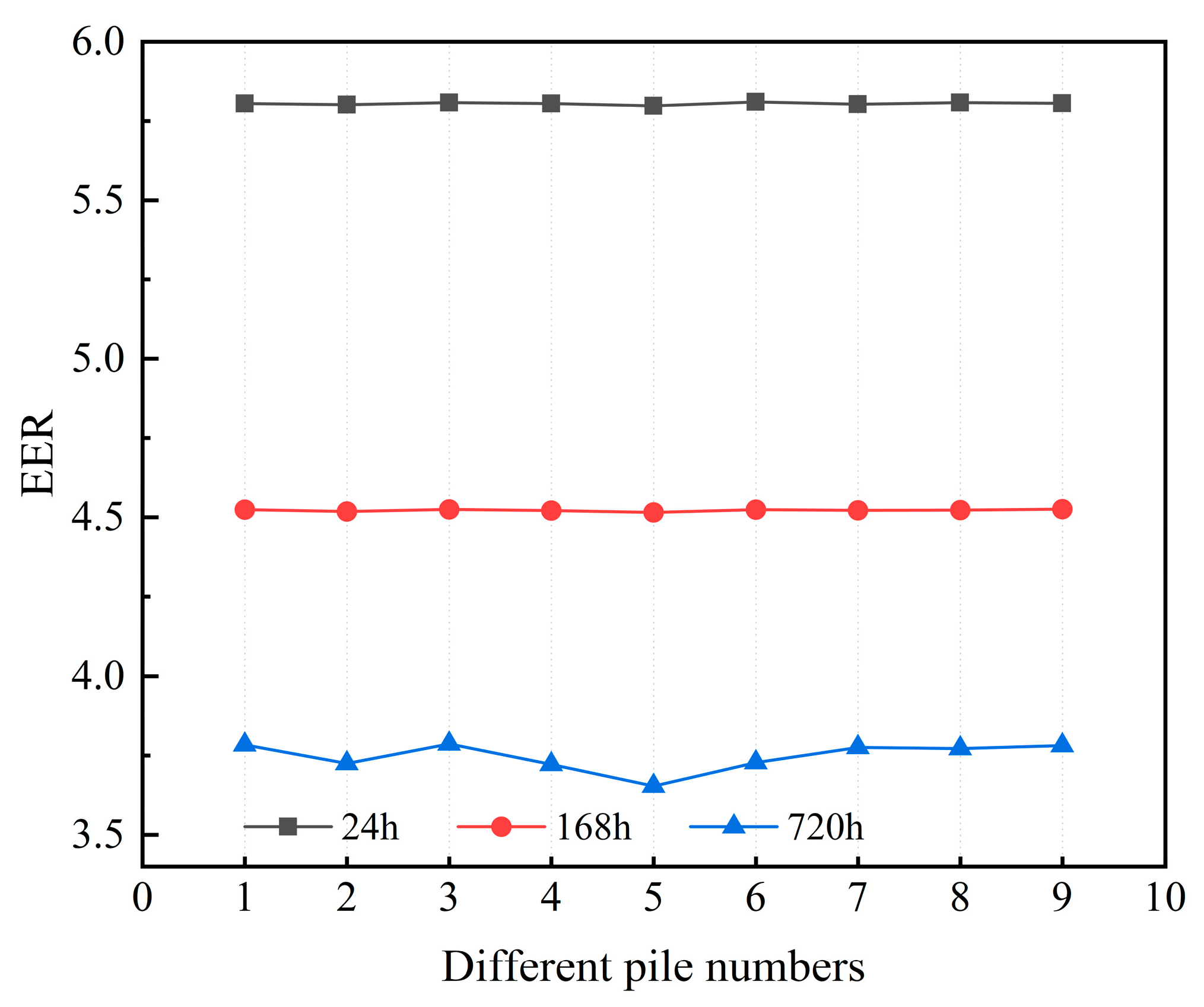
4.3.3. Energy Efficiency Ratio

Figure 16 shows the variation of EER values for each DBP-EP under continuous operational modes at 24 h, 168 h, and 720 h. The data presented in the figure illustrates that under continuous operational modes, the EER values (energy efficiency ratio) of each pile show a decreasing trend with the progression of the heat exchange operation. At different time points, the EER value of pile 5# is lower than the other piles, and this difference gradually increases with the heat exchange operation of the pile group. At 24 h, the disparity in EER values between pile 5# and pile 6# is 0.02, while at 720 h, this difference increases to 0.08. It can be observed that the longer the pile group operates continuously, the greater is the performance degradation, and the more significant is the negative impact regarding the thermal exchange efficiency of the inner piles.
Table 3 shows the average EER values of pile 5# running for 30 days under intermittent operational mode and continuous operational mode. The EER values for Pile 5 under intermittent operational mode surpass those recorded under the continuous operational mode, and the values decrease with the increase of the intermittent ratio. This phenomenon occurs due to variations in rest durations within the intermittent operational mode of the heat pump system, wherein longer periods of rest correspond to reduced electrical energy consumption. With a smaller intermittent ratio n, the instantaneous thermal exchange rate of the pile is heightened, resulting in decreased electrical energy consumption and consequently an increase in the EER value. Based on the aforementioned analysis, it is inferred that optimizing the intermittent ratio can enhance the thermal efficiency of energy pile systems, ensuring effective fulfillment of both heating and cooling requirements within buildings, thus achieving the goal of high efficiency and energy saving operation.

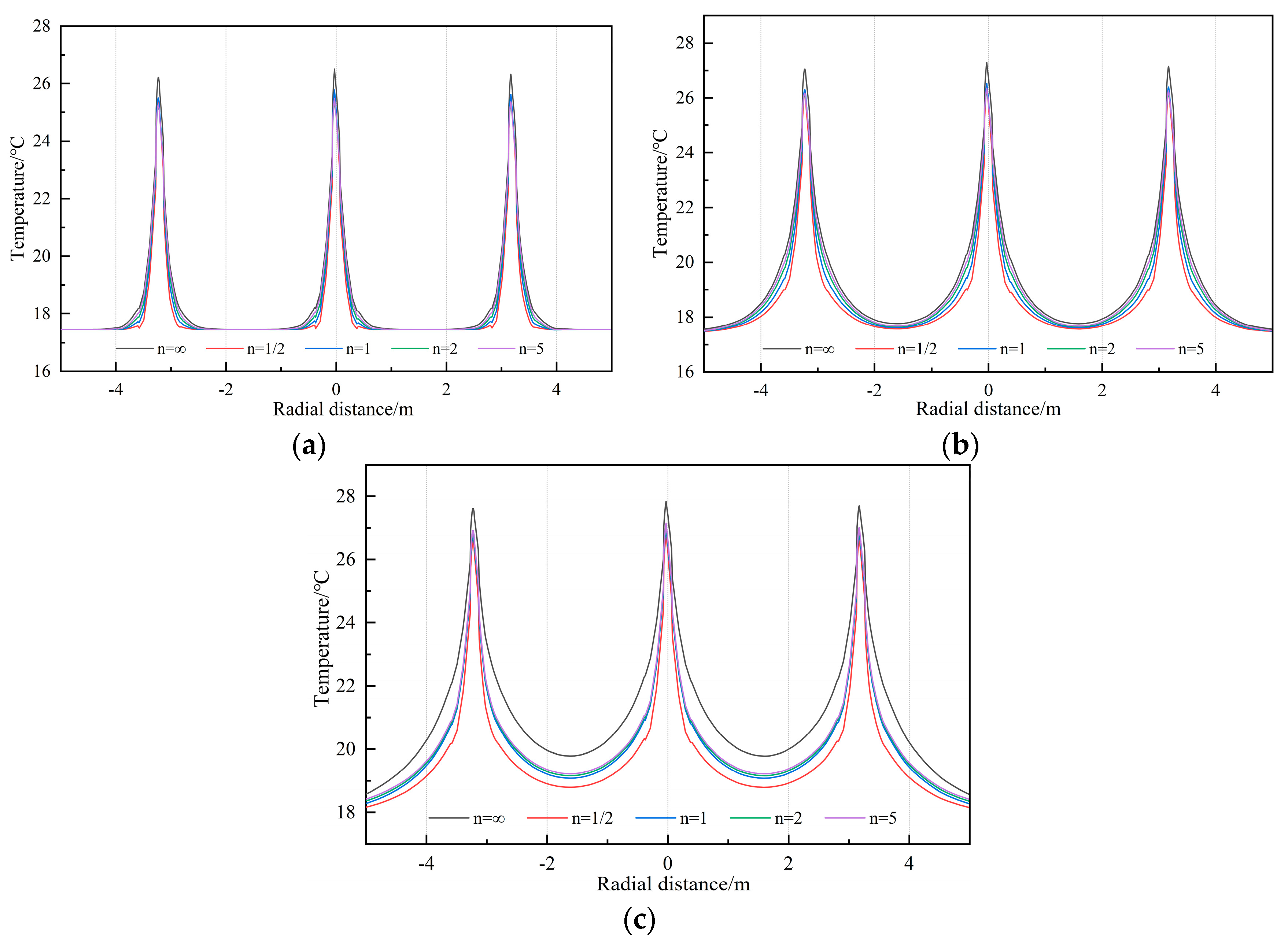
4.4. Comparison and Analysis of Thermal Radius between Continuous and Intermittent Operational Modes

Figure 17 shows the radial temperature changes at a depth of 20 m for piles 4#, 5#, and 6# at different time points (a, b, c represent 24 h, 168 h, and 720 h, respectively) under different operating conditions. The temperatures of the between piles increase gradually with time, and the thermal radius of each individual pile also increases. In the mode of intermittent operation, both the internal temperature and the thermal radius distribution of the DBP-EP are smaller than those in the continuous operational mode. It can be seen from Table 4, from 24 h to 168 h, the temperature of the soil at a radial distance of 0.8 m increases by 0.87 °C and 0.55 °C for intermittent ratios of n = 5 and n = 1/2, respectively, which are lower than the temperature increments of 0.08 °C and 0.40 °C in the continuous operational mode. From 168 h to 720 h, the elevations in temperature by 1.49 °C and 1.30 °C, respectively, are lower than the temperature increments of 0.67 °C and 0.86 °C in the continuous operational mode. Perhaps this is because reducing the batch ratio can dissipate the internal heat of the pile, diminish the collective influence of the pile group, and maintain a high instantaneous heat exchange rate of the pile.

4.5. Potential Applications and Developments

In this paper, the differences and similarities of heat transfer performance of deep-buried tubular energy piles under different operational strategies were analyzed and studied by combining an in situ test and a numerical simulation for single and group piles of deep-buried tubular energy piles. Certain suggestions are put forward for the follow-up operation plan of deep-buried tubular energy piles. However, there are still shortcomings in the discussion process and many problems need to be further improved:
  • The selection of the intermittent operation scheme and operation factor change is limited, and the selection range of running time should be further broadened to facilitate more extensive research and analysis.
  • In the process of pile group research, numerical simulation is the main method, and the corresponding practical pile group engineering should be established.
  • The application of the intermittent operational mode should be popularized, and more practical data in the actual project will facilitate the further study.

5. Conclusions

Within this investigation, in situ experiments and numerical simulations were conducted to analyze the differences in heat exchange rate, energy efficiency ratio (EER), and thermal radius between the intermittent and continuous operational modes of the DBP-EP group under summer conditions. The findings can be summarized as follows:
(1)
The continuous operation of deep energy single piles exacerbates the accumulation of heat within the pile foundation, expanding the thermal radius distribution of the pile, also reducing its heat transfer efficiency; furthermore, this exerts adverse effects on the heat transfer performance of the DBP-EP.
(2)
The accumulation of heat and the rate of expansion of the thermal radius within the pile group in continuous operational mode are more pronounced compared to single piles. Under continuous operational conditions, the heat interference generated by the peripheral piles of the pile group has a negative impact on the heat transfer of the inner piles, resulting in a greater reduction in the thermal conductivity characteristics of the inner piles compared to the peripheral piles.
(3)
Combining the analysis of the energy efficiency ratio (EER) and comparing the heat exchange performance between continuous operation and intermittent operational modes, the optimal conclusion was obtained for the intermittent operational mode with an intermittency ratio of n = 5. When the intermittency ratio is n = 5, the total sum of the pile group’s average heat exchange rate decreases by only 0.51% compared to continuous operation, but its single-pile EER is improved by over 19.6%, and to some extent, it alleviates the accumulation of heat within the pile base.
(4)
Analyzing the change of the pile group’s thermal radius during the heat exchange operation in the initial phase, it was found that in the continuous heat exchange operation, thermal interference exerts minimal influence concerning the dynamics of the heat exchange within the pile group. However, as the duration of the heat exchange operation increases, the thermal interference in the pile group gradually becomes more pronounced, leading to a decrease in heat exchange performance. In the intermittent operational mode, the variance in temperature between pile and the soil is recoverable, weakening the pile group effect and favoring the heat exchange operation of the pile group. Therefore, adopting an intermittent operational scheme can effectively improve the thermal exchange performance of the DBP-EP group, providing favorable conditions for the low-energy and efficient operation of the piles.
The above conclusions underscore the advantages of the intermittent operational mode. It is hoped that this mode can be extensively researched for its energy extraction and utilization potential in practical engineering applications, taking into account the varying geological and climatic conditions.

Author Contributions

Methodology, Z.C.; conceptualization, Y.T., Z.C. and J.Y.; software, Y.T.; validation, Y.T., Z.C. and J.Y.; data curation, Y.T.; formal analysis, Y.T.; writing—review and editing, Z.C. and Y.T.; investigation, Z.C.; resources, Z.C.; writing—original draft preparation, Y.T.; supervision, Z.C. and A.M.; visualization, Y.T.; project administration, Z.C. and A.M.; funding acquisition, Z.C. and A.M. All authors have read and agreed to the published version of the manuscript.

Funding

This work was supported by the Key Research and Development Program of Hubei Province (No. 2023BAB024) and the Technology Innovation Project of Hubei Province (No. 2023BEB010).

Institutional Review Board Statement

Not applicable.

Informed Consent Statement

Not applicable.

Data Availability Statement

The data showcased in this investigation are accessible upon inquiry directed to the corresponding author. However, it should be noted that the data cannot be made publicly accessible due to copyright constraints associated with collaborative developers.

Acknowledgments

The author would like to thank Jingmei Wang of China Railway Siyuan Survey and Design Group Co.

Conflicts of Interest

The authors declare that the research was conducted in the absence of any commercial or financial relationships that could be construed as a potential conflict of interest.

References

  1. Xu, Y.-S.; Wang, X.-W.; Shen, S.-L.; Zhou, A. Distribution Characteristics and Utilization of Shallow Geothermal Energy in China. Energy Build. 2020, 229, 110479. [Google Scholar] [CrossRef]
  2. Ramos-Escudero, A.; Gil-García, I.C.; García-Cascales, M.S.; Molina-Garcia, A. Energy, Economic and Environmental GIS–Based Analysis of Shallow Geothermal Potential in Urban Areas—A Spanish Case Example. Sustain. Cities Soc. 2021, 75, 103267. [Google Scholar] [CrossRef]
  3. Lyu, W.; Li, X.; Yan, S.; Jiang, S. Utilizing Shallow Geothermal Energy to Develop an Energy Efficient HVAC System. Renew. Energy 2020, 147, 672–682. [Google Scholar] [CrossRef]
  4. Chicco, J.M.; Antonijevic, D.; Bloemendal, M.; Cecinato, F.; Goetzl, G.; Hajto, M.; Hartog, N.; Mandrone, G.; Vacha, D.; Vardon, P.J. Improving the Efficiency of District Heating and Cooling Using a Geothermal Technology: Underground Thermal Energy Storage (UTES). In New Metropolitan Perspectives; Calabrò, F., Della Spina, L., Piñeira Mantiñán, M.J., Eds.; Lecture Notes in Networks and Systems; Springer International Publishing: Cham, Switzerland, 2022; Volume 482, pp. 1699–1710. ISBN 978-3-031-06824-9. [Google Scholar]
  5. Kong, G.; Fang, J.; Lv, Z.; Yang, Q. Effects of Pile and Soil Properties on Thermally Induced Mechanical Responses of Energy Piles. Comput. Geotech. 2023, 154, 105176. [Google Scholar] [CrossRef]
  6. Tian, W.; Cheng, X.; Liu, Z.; Wei, Q.; Wang, T.; Guo, H. Heat Exchange Performance of an Energy-Pile Group in a Hybrid GSHP System and Effects of Pile Spacing. Energy Build. 2024, 316, 114347. [Google Scholar] [CrossRef]
  7. Shang, Y.; Dong, M.; Mu, L.; Liu, X.; Huang, X.; Li, S. The Analysis of the Evaporation Effect on Moisture Soil under Intermittent Operation of Ground-Source Heat Pump. Energy Procedia 2019, 158, 1508–1513. [Google Scholar] [CrossRef]
  8. Yuan, T.; Yu, M.; Mao, Y.; Cui, P.; Zhang, W.; Zhuang, Z. Study on Long-Term Operation Characteristics of the Medium-Deep Ground Source Heat Pump System with Solar Heat Storage. Appl. Therm. Eng. 2024, 241, 122345. [Google Scholar] [CrossRef]
  9. Pourier, C.; Beltrán, F.; Sommerfeldt, N. Solar Photovoltaic/Thermal (PVT) Technology Collectors and Free Cooling in Ground Source Heat Pump Systems. Sol. Energy Adv. 2024, 4, 100050. [Google Scholar] [CrossRef]
  10. Linfeng, Z.; Quan, Z.; Min, L.; Yaxing, D. A New Analytical Model for the Underground Temperature Profile under the Intermittent Operation for Ground-Coupled Heat Pump Systems. Energy Procedia 2015, 75, 840–846. [Google Scholar] [CrossRef]
  11. Zhang, X.; Wang, E.; Liu, L.; Qi, C.; Zhen, J.; Meng, Y. Analysis of the Operation Performance of a Hybrid Solar Ground-Source Heat Pump System. Energy Build. 2022, 268, 112218. [Google Scholar] [CrossRef]
  12. Qiu, G.; Li, K.; Cai, W.; Yu, S. Optimization of an Integrated System Including a Photovoltaic/Thermal System and a Ground Source Heat Pump System for Building Energy Supply in Cold Areas. Appl. Energy 2023, 349, 121698. [Google Scholar] [CrossRef]
  13. Gao, B.; Zhu, X.; Yang, X.; Yuan, Y.; Yu, N.; Ni, J. Operation Performance Test and Energy Efficiency Analysis of Ground-Source Heat Pump Systems. J. Build. Eng. 2021, 41, 102446. [Google Scholar] [CrossRef]
  14. You, T.; Zeng, W. Zoning Operation of Energy Piles to Alleviate the Soil Thermal Imbalance of Ground Source Heat Pump Systems. Energy Built Environ. 2023, 4, 57–63. [Google Scholar] [CrossRef]
  15. Chen, Z.; Yao, J.; Pan, P.; Xiao, H.; Ma, Q. Research on the Heat Exchange Characteristics of the Deeply Buried Pipe Type of Energy Pile. Case Stud. Therm. Eng. 2021, 27, 101268. [Google Scholar] [CrossRef]
  16. Sadeghi, H.; Singh, R.M. Driven Precast Concrete Geothermal Energy Piles: Current State of Knowledge. Build. Environ. 2023, 228, 109790. [Google Scholar] [CrossRef]
  17. Sani, A.K.; Singh, R.M. Response of Unsaturated Soils to Heating of Geothermal Energy Pile. Renew. Energy 2020, 147, 2618–2632. [Google Scholar] [CrossRef]
  18. Liu, H.; Wang, X.; Wang, K.; Zhu, Y.; Zhu, Y. Numerical Analysis of Ground Temperature Response Characteristics of a Space-Heating Ground Source Heat Pump System by Utilizing Super-Long Flexible Heat Pipes for Heat Extraction. Energy Build. 2021, 244, 110991. [Google Scholar] [CrossRef]
  19. Xu, Y.; Zeng, Z.; Sun, D. Experimental and Numerical Investigation on Heat Transfer Characteristics of Vertical Ground Heat Exchangers in Karst Areas. Energy Build. 2022, 275, 112481. [Google Scholar] [CrossRef]
  20. Li, C.; Jiang, C.; Guan, Y.; Meng, Q.; Chen, H.; Zhang, S. Evaluation of Heating Capacity of Shallow Ground Heat Exchangers in Different Locations—A Case Study of Two Administrative Districts of Xi’an. Energy Build. 2023, 294, 113276. [Google Scholar] [CrossRef]
  21. Rajeh, T.; Al-Kbodi, B.H.; Li, Y.; Zhao, J.; Zhang, Y. Modeling and Techno-Economic Comparison of Two Types of Coaxial with Double U-Tube Ground Heat Exchangers. Appl. Therm. Eng. 2023, 225, 120221. [Google Scholar] [CrossRef]
  22. Sutman, M.; Speranza, G.; Ferrari, A.; Larrey-Lassalle, P.; Laloui, L. Long-Term Performance and Life Cycle Assessment of Energy Piles in Three Different Climatic Conditions. Renew. Energy 2020, 146, 1177–1191. [Google Scholar] [CrossRef]
  23. Li, R.; Kong, G.; Chen, Y.; Yang, Q. Thermomechanical Behaviour of an Energy Pile–Raft Foundation under Intermittent Cooling Operation. Geomech. Energy Environ. 2021, 28, 100240. [Google Scholar] [CrossRef]
  24. Cao, Z.; Zhang, G.; Liu, Y.; Zhao, X.; Li, C. Influence of Backfilling Phase Change Material on Thermal Performance of Precast High-Strength Concrete Energy Pile. SSRN J. 2021. [Google Scholar] [CrossRef]
  25. Cui, Y.; Zhu, J. CFD Assessment of Multiple Energy Piles for Ground Source Heat Pump in Heating Mode. Appl. Therm. Eng. 2018, 139, 99–112. [Google Scholar] [CrossRef]
  26. Jahangir, M.H.; Ghazvini, M.; Pourfayaz, F.; Ahmadi, M.H. A Numerical Study into Effects of Intermittent Pump Operation on Thermal Storage in Unsaturated Porous Media. Appl. Therm. Eng. 2018, 138, 110–121. [Google Scholar] [CrossRef]
  27. Liang, B.; Chen, M.; An Fu, B.; Guan, J. Thermal and Flow Characteristics in a Vertical Spiral-Type Ground Heat Exchanger Based on Linear Non-Equilibrium Thermodynamic Principle. Energy Build. 2022, 266, 112111. [Google Scholar] [CrossRef]
  28. Yang, J.; Xu, L.; Hu, P.; Zhu, N.; Chen, X. Study on Intermittent Operation Strategies of a Hybrid Ground-Source Heat Pump System with Double-Cooling Towers for Hotel Buildings. Energy Build. 2014, 76, 506–512. [Google Scholar] [CrossRef]
  29. Behbehani, F.; McCartney, J.S. Energy Pile Groups for Thermal Energy Storage in Unsaturated Soils. Appl. Therm. Eng. 2022, 215, 119028. [Google Scholar] [CrossRef]
  30. Xu, B.; Zhang, H.; Chen, Z. Study on Heat Transfer Performance of Geothermal Pile-Foundation Heat Exchanger with 3-U Pipe Configuration. Int. J. Heat Mass Transf. 2020, 147, 119020. [Google Scholar] [CrossRef]
  31. Noye, S.; Mulero Martinez, R.; Carnieletto, L.; De Carli, M.; Castelruiz Aguirre, A. A Review of Advanced Ground Source Heat Pump Control: Artificial Intelligence for Autonomous and Adaptive Control. Renew. Sustain. Energy Rev. 2022, 153, 111685. [Google Scholar] [CrossRef]
  32. Hou, G.; Taherian, H.; Song, Y.; Jiang, W.; Chen, D. A Systematic Review on Optimal Analysis of Horizontal Heat Exchangers in Ground Source Heat Pump Systems. Renew. Sustain. Energy Rev. 2022, 154, 111830. [Google Scholar] [CrossRef]
  33. Zhou, K.; Mao, J.; Zhang, H.; Li, Y.; Yu, X.; Chen, F.; Li, M. Design Strategy and Techno-Economic Optimization for Hybrid Ground Heat Exchangers of Ground Source Heat Pump System. Sustain. Energy Technol. Assess. 2022, 52, 102140. [Google Scholar] [CrossRef]
  34. Huang, G.; Liao, Z.; Li, S.; Zhuang, C.; Zhang, H.; Cheng, L.; Gan, F.; Xu, N. A Novel Independent Heat Extraction-Release Double Helix Energy Pile: Numerical and Experimental Investigations of Heat Extraction Effect. Energy Convers. Manag. 2022, 254, 115249. [Google Scholar] [CrossRef]
  35. Lee, S.; Park, S.; Kim, D.; Ahn, D.; Choi, H. Dual Performance of Novel Steel Pipe Heat Exchangers Equipped in Cast-in-Place Energy Pile. Energy Build. 2021, 234, 110725. [Google Scholar] [CrossRef]
  36. Han, C.; Zhu, C.; Shen, Y.; Yu, X.B. Energy, Environmental and Economic Performance Evaluation of Energy Pile System under Different Climate Conditions. Energy Convers. Manag. 2022, 252, 115041. [Google Scholar] [CrossRef]
  37. Lyu, W.; Pu, H.; Xiao, H.; Hu, D.; Ma, Q. Thermal Performance of Energy Pile with Deeply Penetrating 1-U-Shape Heat Exchanger. Geothermics 2021, 91, 102023. [Google Scholar] [CrossRef]
  38. Nicholls, P. Formate as an Inhibitor of Cytochrome c Oxidase. Biochem. Biophys. Res. Commun. 1975, 67, 610–616. [Google Scholar] [CrossRef]
Figure 1. Test site location and general situation.
Applsci 14 05928 g001
Figure 2. Energy pile overall structure diagram.
Applsci 14 05928 g002
Figure 3. Stratigraphic distribution.
Applsci 14 05928 g003
Figure 4. Temperature curve of entry and exportation of DBP-EP test.
Applsci 14 05928 g004
Figure 5. DBP-EP simulation model and mesh division.
Applsci 14 05928 g005
Figure 6. Field test and model comparison.
Applsci 14 05928 g006
Figure 7. The temporal evolution of peak core temperature and heat exchange rate during continuous operational mode.
Applsci 14 05928 g007
Figure 8. The thermal radius distribution of deep-buried tubular energy pile changes at different time periods.
Applsci 14 05928 g008
Figure 9. Aerial view of the 2D domain with the nine points representing the foundation piles.
Applsci 14 05928 g009
Figure 10. Temperature change of 20 m deep-pile group.
Applsci 14 05928 g010
Figure 11. The temperature difference of entry and exportation water between deep-buried tubular energy pile and pile 5# varies with time.
Applsci 14 05928 g011
Figure 12. Changes of radial temperature of pile 4#, 5#, and 6# and the maximum temperature of single pile core at 20 m depth.
Applsci 14 05928 g012
Figure 13. Temporal variation in thermal exchange rate of pile groups under continuous operational regime.
Applsci 14 05928 g013
Figure 14. Temporal evolution of heat exchange rate in pile 5# during intermittent operational mode.
Applsci 14 05928 g014
Figure 15. Variation in heat exchange rates between the 5# pile foundation and deep well across diverse operational modes. The dashed line in the gray box indicates the result emphasizing that “when the intermittent ratio is n = 5, the setting of deep well can better enhance the heat dissipation effect of the heat carrier fluid in the heat exchange pipe system, so as to improve the heat transfer performance of pile foundation”.
Applsci 14 05928 g015
Figure 16. EER changes of pile group at different time periods in continuous operational mode.
Applsci 14 05928 g016
Figure 17. Radial temperature variation at 20 m pile depth under various intermittent operational conditions at different time periods. ((a) = 24 h, (b) = 168 h, (c) = 720 h).
Applsci 14 05928 g017
Table 1. Physical parameters of formation materials.
MaterialDensity
(kg/m3)
Thermal
Conductivity (W/(m⋅°C))
Porosity
Backfill (fine sand)17500.580.45
Pile (concrete)23502.200
Fine sand23502.500.45
Clay20001.000.40
Gravel20002.310.30
Mudstone 120001.900.25
Mudstone 220001.900.20
Mudstone 320001.900.15
Table 2. Mean heat exchange rate of the pile group during a 30-day operational period.
Intermittent Condition1#2#3#4#5#
n = ∞ (Q/W)4145.504123.924147.414124.914100.55
n = 5 (Q/W)4119.89
(↓0.62%)
4103.04
(↓0.51%)
4122.55
(↓0.60%)
4103.78
(↓0.51%)
4084.17
(↓0.40%)
n = 2 (Q/W)3474.04
(↓16.20%)
3461.67
(↓16.06%)
3475.53
(↓16.20%)
3463.23
(↓16.04%)
3449.75
(↓15.87%)
n = 1 (Q/W)2849.55
(↓31.26%)
2840.92
(↓31.11%)
2850.52
(↓31.27%)
2842.67
(↓31.09%)
2833.64
(↓30.90%)
n = 1/2 (Q/W)2562.22
(↓38.19%)
2555.89
(↓38.02%)
2562.69
(↓38.20%)
2557.66
(↓37.99%)
2551.54
(↓37.78%)
6#7#8#9#Total
n = ∞ (Q/W)4123.834141.554123.534146.0137,177.21
n = 5 (Q/W)4108.07
(↓0.38%)
4117.24
(↓0.59%)
4105.99
(↓0.43%)
4121.68
(↓0.59%)
36,986.41
(↓0.51%)
n = 2 (Q/W)3466.32
(↓15.94%)
3471.75
(↓16.17%)
3464.91
(↓15.97%)
3474.68
(↓16.19%)
31,201.88
(↓16.07%)
n = 1 (Q/W)2845.12
(↓31.01%)
2847.78
(↓31.24%)
2844.21
(↓31.02%)
2849.82
(↓31.26%)
25,604.23
(↓31.13%)
n = 1/2 (Q/W)2559.77
(↓37.93%)
2560.67
(↓38.17%)
2559.05
(↓37.94%)
2562.34
(↓38.19%)
23,031.83
(↓38.05%)
Table 3. EER mean for 30 days of operation of 5# piles in intermittent and continuous operational mode.
Intermittent Ratio (n)n = ∞n = 5n = 2n = 1n = 1/2
EER4.325.375.616.107.20
Table 4. Soil temperature at 0.8 under different operating modes.
Temperature at 0.8 m (°C)n = ∞n = 1/2n = 1n = 2n = 5
24 h17.5017.4517.4617.4617.47
168 h18.4518.0018.1318.2618.34
178 h20.6119.3019.6919.7719.83
Disclaimer/Publisher’s Note: The statements, opinions and data contained in all publications are solely those of the individual author(s) and contributor(s) and not of MDPI and/or the editor(s). MDPI and/or the editor(s) disclaim responsibility for any injury to people or property resulting from any ideas, methods, instructions or products referred to in the content.

