Article

Concrete Gas Permeability: Implications for Hydrogen Storage Applications

by
Luana Abreu Araujo
1,*,
Nuria Rebolledo Ramos
1,
Julio Emilio Torres Martín
1,
Servando Chinchón-Payá
1,
Javier Sánchez Montero
1,
Rosa Maria Lample Carreras
2,
Jose Vera-Agullo
2 and
Jose David Jimenez-Vicaria
2
1
Department of Reinforcement Corrosion and Structural Safety, Eduardo Torroja Institute for Construction Science—CSIC, 28033 Madrid, Spain
2
Acciona Construcción, S.A., 28108 Alcobendas, Spain
*
Author to whom correspondence should be addressed.
Appl. Sci. 2024, 14(15), 6408; https://doi.org/10.3390/app14156408
Submission received: 17 June 2024 / Revised: 15 July 2024 / Accepted: 17 July 2024 / Published: 23 July 2024
(This article belongs to the Section Materials Science and Engineering)

Abstract

:
Concrete is widely utilized across various industries as a containment material. One essential property related to its performance is permeability, which determines its ability to allow the passage of gases or liquids through its pores and capillaries and even the transmission of aggressive agents. This study focused on investigating the permeability of gases with varying atomic weights and molecular volumes, such as helium, nitrogen, oxygen, and argon, to pass through concrete. The primary objective was to determine the significance of variation in permeability and to evaluate and differentiate their behavior. To achieve this, concrete test specimens were employed, and factors such as cold joint impact, gas pressure, and specimen saturation levels were considered. Throughout the study, changes in weight, specimen humidity, resistivity, and ultrasonic pulse velocity were monitored. The findings suggested that within concrete, the variation in permeability for these gases is negligible. By utilizing the acquired data, the present study estimated the permeability of hydrogen through mathematical models based on gas pressure and concrete thickness. These insights contribute to a deeper comprehension of concrete gas permeability and its potential impact on improving hydrogen containment.

1. Introduction

In the pursuit of sustainable energy solutions, hydrogen has emerged as a promising vector for clean and efficient power generation. With its high energy density and ability to produce only water as a byproduct, hydrogen offers a tantalizing vision of a greener future. However, realizing this potential requires safe and reliable means of storing and transporting hydrogen gas [1,2].
Natural caves or geological formations have been considered potential hydrogen storage solutions. These formations offer large underground spaces with minimal modification requirements. Such caves provide a natural containment system, which can be beneficial for the large-scale storage of hydrogen [3,4]. The primary advantage of using natural caves lies in their cavernous capacity, enabling the storage of vast quantities of hydrogen, and their geological properties can often create an impermeable barrier, reducing the risk of hydrogen leakage. Additionally, natural caves can have stable and favorable temperature conditions, which can enhance the safety and stability of hydrogen stored within them [5].
However, using natural caves for hydrogen storage also presents challenges. Retrofitting these caves for hydrogen containment may require substantial investment and engineering expertise. Furthermore, access and monitoring of the stored hydrogen can be more complicated compared to concrete structures, which can be more easily designed with built-in safety features [6].
Facing that, concrete has been widely used in various industries and construction applications, and its properties can make it suitable for hydrogen containment [7,8]. The main advantage of using concrete is that it can be shaped into various forms, allowing for the construction of custom-designed storage facilities or vessels for hydrogen gas. Additionally, with advancements in concrete technology, it is possible to produce low-permeability concrete that significantly reduces the transport of hydrogen molecules, enhancing safety and containment efficiency [9,10].
Concrete gas permeability, which determines the flow of gases through its pores and capillaries, is a critical factor to consider. To ensure effective hydrogen containment, engineers and researchers strive to optimize the concrete’s composition and microstructure, aiming for lower porosity and increased impermeability. As a result, concrete becomes a viable and cost-effective option for storing hydrogen at various scales, from small stationary systems to larger industrial facilities [11].
This article explores the intricate relationship between concrete permeability and its pivotal role in securing hydrogen gas, thereby addressing a significant research need in the field of sustainable energy solutions.

Concrete Permeability

Permeability is the capacity of a material to allow a fluid to pass through it without altering its composition. A material is considered impermeable or non-permeable when the amount of fluid passing through it is negligible [12,13].
The rate at which a fluid passes through the material depends on three fundamental factors:
  • The porosity of the material and its structure: the volume, size, and distribution of the pores regulate the rate at which it absorbs liquids, mainly water containing certain aggressors and gases.
  • The viscosity of the considered fluid, which is affected by its temperature.
  • The pressure to which the fluid is subjected.
Concerning the material and its structure, concrete is a heterogeneous material, dense but porous, as it allows a considerable amount of fluid to pass through it within a given time. It consists of a solid phase and a porous space or void volume, representing between 8% and 25% of the total volume [14].
The concrete presents a network of pores of different sizes which can reach the surface [15]. To be permeable, it must not only present pores but also have interconnected void spaces that allow for fluid passage [16,17].
In terms of durability, the most critical pores are those between 10−2 and 10−7 m (compaction pores, entrapped air, and capillary pores), while micro pores or gel pores have no incidence due to their size. Capillary pores, with a radius between 10 and 1000 nm, result from spaces initially occupied by mixing water and subsequently partially filled with hydration products.
The most common hydration products include the following:
  • Calcium silicate hydrate (C-S-H): It is the main hydration product of Portland cement and forms through the reaction of cement with water. This gel is amorphous and extends throughout the concrete matrix, filling the pores and voids of the material.
  • Calcium hydroxide (CH): This is another common hydration product formed through the reaction of cement with water. CH is crystalline and is deposited in the pores and voids of concrete, where it can react with other compounds to form additional products. It gives the concrete a highly alkaline character, ranging from pH 12 to 13 (protective for reinforcement).
  • Ettringite: This is a compound of calcium sulfate hydrate and aluminum that is formed when sulfate-containing cement is used. This product can be deposited in the pores and voids of concrete, contributing to the formation of the material’s crystalline structure.
  • Hydrated silica: This is a compound that forms through the reaction of cement with silica. This hydration product is deposited in the pores and voids of concrete, contributing to its strength and durability.
The hydration products formed during cement hydration in concrete play pivotal roles in reducing permeability [18]. They fill voids and pores, hindering the movement of gases and liquids. The C-S-H gel acts as a binding agent, forming a cohesive structure that resists fluid and gas flow. This process modifies the pore structure, creating smaller, interconnected pores that further impede permeability. Additionally, hydration products enhance chemical resistance, protecting concrete from deterioration and maintaining its long-term performance. Understanding these roles is essential for optimizing concrete mix designs, particularly in applications like hydrogen storage, where gas containment is critical.
Besides hydration products, aggregate size significantly influences concrete porosity. Well-graded aggregates optimize packing and reduce permeability, while larger sizes increase the spacing between particles, potentially increasing permeability [19].
Concrete permeability is crucial for achieving greater durability and strength. Low-permeability concrete has a reduced water–cement (w/c) ratio and satisfactory moisture absorption capacity, allowing fewer aggressive agents to enter and making it more durable [20,21,22]. It has been studied that a lower w/c ratio significantly reduces permeability to lower levels by promoting a denser concrete matrix with fewer interconnected voids. Moreover, the incorporation of superplasticizers in the concrete mix enables the achievement of low w/c ratios, thereby producing concrete with enhanced durability and reduced permeability. These improvements are crucial for ensuring the long-term performance and sustainability of concrete structures [23,24].
Another factor that may influence the permeability of concrete structures is the presence of cold joints. A cold joint refers to a point or interface where two separate batches of concrete meet and bond together, possibly improperly or less effectively [25]. Cold joints occur when there is a time gap between the placement of the first concrete pour and the subsequent pour. These joints can have various causes and consequences, especially concerning reductions in the structure’s strength and durability [26,27].
Hydrogen, aside from being explosive, has a small atom size, which makes it highly permeable and can cause hydrogen embrittlement in metals, making its storage very challenging.
One of the standards that studies gas permeability in concrete is UNE 83981 [28], which determines the permeability of hardened concrete to oxygen. Determining O2 permeability is of critical importance due to the fact that it has been demonstrated that in the presence of oxygen and a sufficient amount of chloride ions dissolved in the water in the concrete pores, steel corrosion occurs, even under high alkaline conditions. In such circumstances, structural failures can occur due to fractures or weak points, as mentioned above.
As gases of different sizes also penetrate concrete but have not been studied, this study includes studying oxygen, helium, nitrogen, and argon. Helium is particularly important because hydrogen cannot be directly tested due to its explosiveness, and helium is the gas that most closely resembles it in size. Therefore, data can be extrapolated to approximate hydrogen permeability [29,30,31].
The objective is to verify if the variation among different gases is significant and, if so, to evaluate and differentiate their behavior. The comparison between specimens with and without cold joints is also evaluated to determine the durability issues that they can cause to the structure regarding gas permeability. Additionally, the data will be used to estimate hydrogen permeability based on gas pressure and concrete thickness, which leads to estimating the containment capacity.

2. Experimental Development

2.1. Materials

The materials used in the experimental study include different gases, helium, nitrogen, oxygen, and argon, which have been tested on different batches of concrete specimens (Table 1) conditioned at different relative humidities.
Three types of conditioning of specimens were tested:
  • Air: Specimens were placed in the oven at 50 °C, as described in the UNE 83966 procedure [32], and weighed daily until there was no further mass variation. They were then left under laboratory conditions (20 ± 2 °C and relative humidity above 45%) for two to four days before testing.
  • Controlled relative humidity (RH): specimens conditioned to 65% RH.
  • Saturated: specimens were submerged in water and weighed daily until there was no mass variation (100% RH).
Both types of cement used in our samples contribute to specific properties and performance characteristics tailored to their respective applications in precast elements with high early-age strengths and slip-form concrete. They enhance early-age strength, durability, workability, and sustainability, addressing some of the requirements for H2 storage. While these mixes may not represent the only types used for such structures, they were chosen based on practical considerations and realistic scenarios.
As mentioned, specimens with cold joints were tested. These joints were fabricated by filling half of the specimen mold with one batch of concrete and then filling the other half with another batch on a different day, using the same mixing proportions. The time lapse between the two pours was one day, allowing the first pour to harden sufficiently to support the second layer but not fully cure, thereby creating a cold joint. After 24 h, it could be assumed that the first layer of concrete had reached its initial set but was still somewhat green. The cold joints were parallel to the gas flow.

2.2. Techniques and Normative

The following techniques have been employed in the experimental study, following each respective standard:
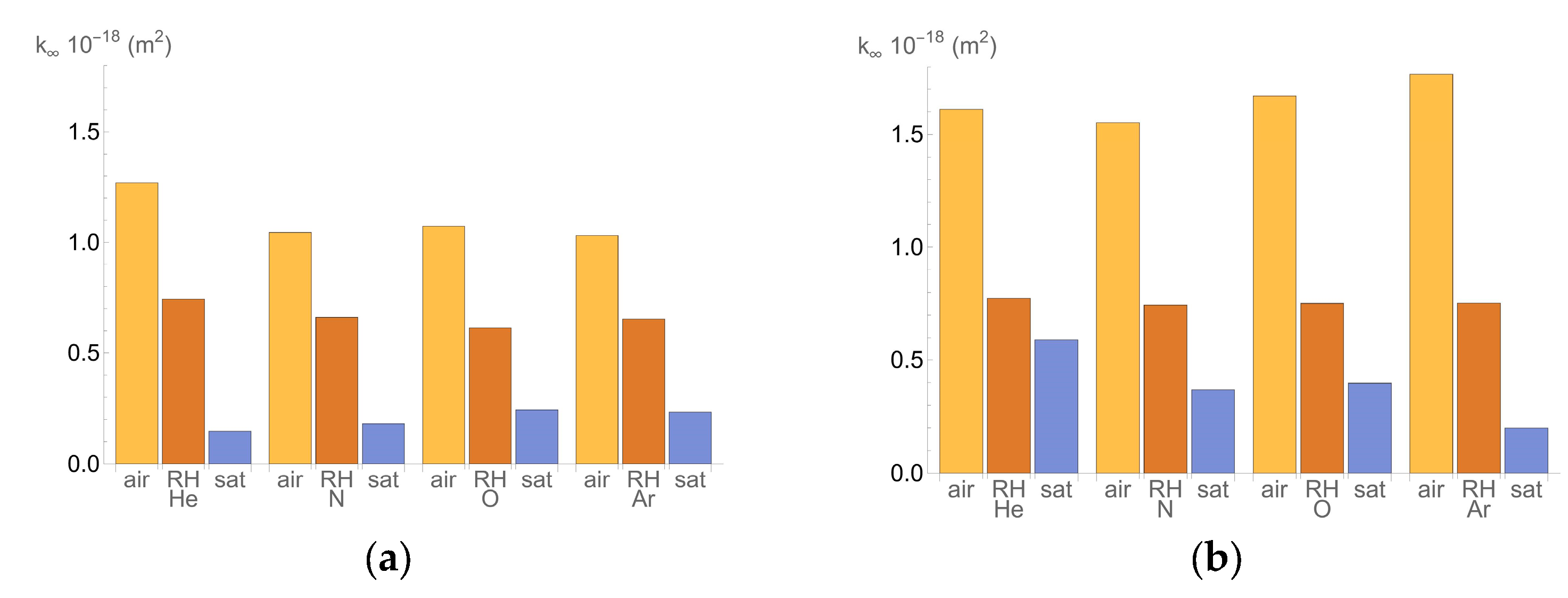
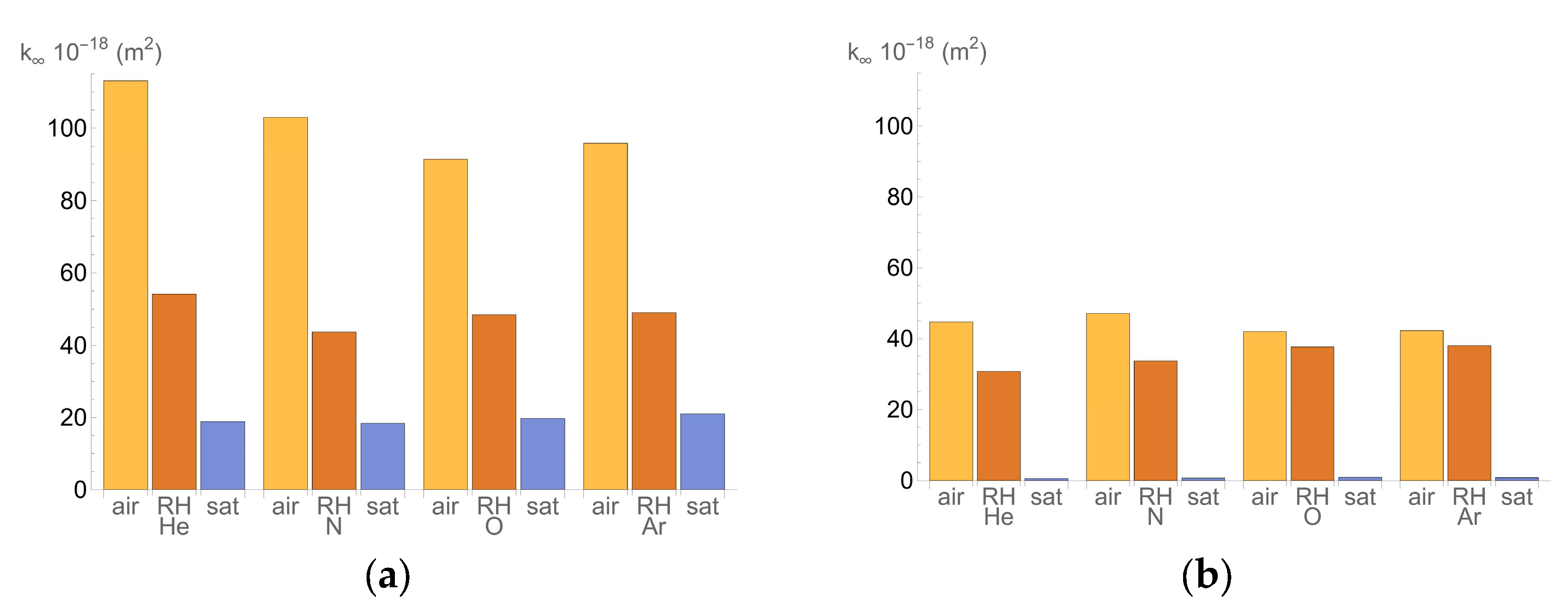
  • Permeability Measurement: The permeability of hardened concrete to oxygen has been determined following the procedure specified in the UNE 83981 standard. Additionally, three other gases (helium, nitrogen, and argon) have been tested to observe any significant differences between them.
  • Preparation and Curing of Specimens: the preparation and curing of concrete specimens for resistance tests have been carried out according to the UNE-EN 12390-2:2020 standard [33].
  • Conditioning of Concrete Specimens: the UNE 83966 standard has been used to condition the concrete specimens for gas and capillarity permeability tests.
  • Resistivity Measurement: the resistivity of the concrete specimens has been measured directly, following the UNE-EN 12390-19:2023 [34].
  • Ultrasonic Testing: ultrasonic testing has been conducted as per the UNE-EN 12504-4:2022 standard [35].

2.3. Procedures

The experimental procedures initiated with the oxygen permeability measurement, which was determined in hardened concrete by applying different gas pressures under laminar flow conditions. The flow rates through the test specimen per unit time were measured.
The test specimens had a cylindrical geometry with flat faces, sensibly perpendicular to their axis, a thickness of 50 ± 2 mm, and an effective diameter of 75 ± 2 mm, 100 ± 2 mm, or 150 ± 2 mm.
To start the test, the specimen was placed inside the cell, where it was sealed with a polyurethane collar. On one of the surfaces, the gas was applied and had to pass through the specimen in order to leave from the other surface. The gas that passed through the concrete left the test cell in a tube that was connected to the graduated tube so that the flow could be measured.
Five pressure values for each gas were used. Multiple measurements were taken for each pressure until three with an error of less than 3% were obtained. Pressure values between 0.5 and 3.5 bar were used. The average flow values obtained at different pressures for the same specimen were considered. For the final calculation, average values of at least 5 measurements of the diameter and height of the specimen were taken.
To calculate the permeability coefficient, Equation (1) is used, considering each gas’s respective dynamic viscosities, as shown in Table 2.
Table 2. Gas properties.
GasViscosity (10−5 Pa·s)Atomic Mass (g/mol)Density (g/mL)
Hydrogen0.84001.007970.071
Helium1.94604.00260.126
Nitrogen1.766014.00670.810
Oxygen2.026015.99941.429
Argon2.215039.94801.400
K = 2 · Q · p 0 · L ·   A ( p 2 p a 2 )
where:
  • K is the permeability coefficient of oxygen (m2);
  • Q is the gas flow through the specimen (m3/s);
  • p0 is the pressure at which Q (m3/s) is determined (considered equal to pa) (N/m2);
  • L is the thickness of the specimen (m);
  • is the viscosity of the gas (N·s/m2);
  • A is the cross-sectional area of the specimen (m2);
  • p is the pressure applied during the test (N/m2);
  • pa is the atmospheric pressure (N/m2).
In order to determine the conditions of the specimens properly, other tests have been performed. After testing each specimen, they were weighed, and their resistivity was measured using direct or indirect methods (depending on the specimen’s size) and ultrasonic testing using both direct and indirect methods.
The electrical resistivity of hardened concrete indirectly indicates the connectivity and size of its pores and the degree of liquid saturation in its porous network [36]. A higher water content in the concrete results in lower electrical resistivity.
The electrical resistivity can be measured indirectly using the four-point or Wenner method and directly using a potentiostat/galvanostat [37]. The four-point method applies a stable current between the external electrodes and measures the change in potential difference between the internal electrodes. According to the standard mentioned, the four-point method involves applying a current between two electrodes positioned on a surface of the specimen and measuring the voltage between the two interior electrodes aligned with the former. This method allows for the determination of electrical resistance [38,39]. For the direct measurement, a modification of the UNE-EN 12390-19 standard was followed. Equations (2) and (3) are used to calculate the resistivity through the Wenner method and the direct method, respectively:
ρ i n d i r e c t = 2 π · a · R
ρ d i r e c t = S l · R
where:
  • a is the distance between each of the four equally spaced electrodes (m);
  • 2 π is the geometry factor for semi-infinite concrete elements, expressed as a non-dimensional parameter;
  • R is the electrical resistance (Ω);
  • S is the cross-section area of the sample (m2);
  • l is the height of the specimen or the distance between electrodes (m).
The ultrasonic testing equipment consists of an electrical pulse generator, a pair of transducers, and an electronic timer for measuring the time interval between the start of the wave and its arrival at the receiving transducer [40,41]. This testing is essential for evaluating the integrity and homogeneity of concrete samples. It allows for the detection of internal flaws, such as voids, cracks, or delaminations, which are crucial factors affecting the structural performance and durability of concrete.

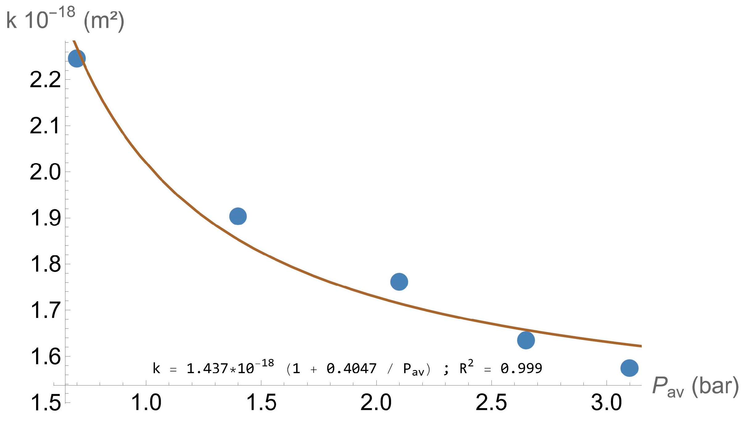
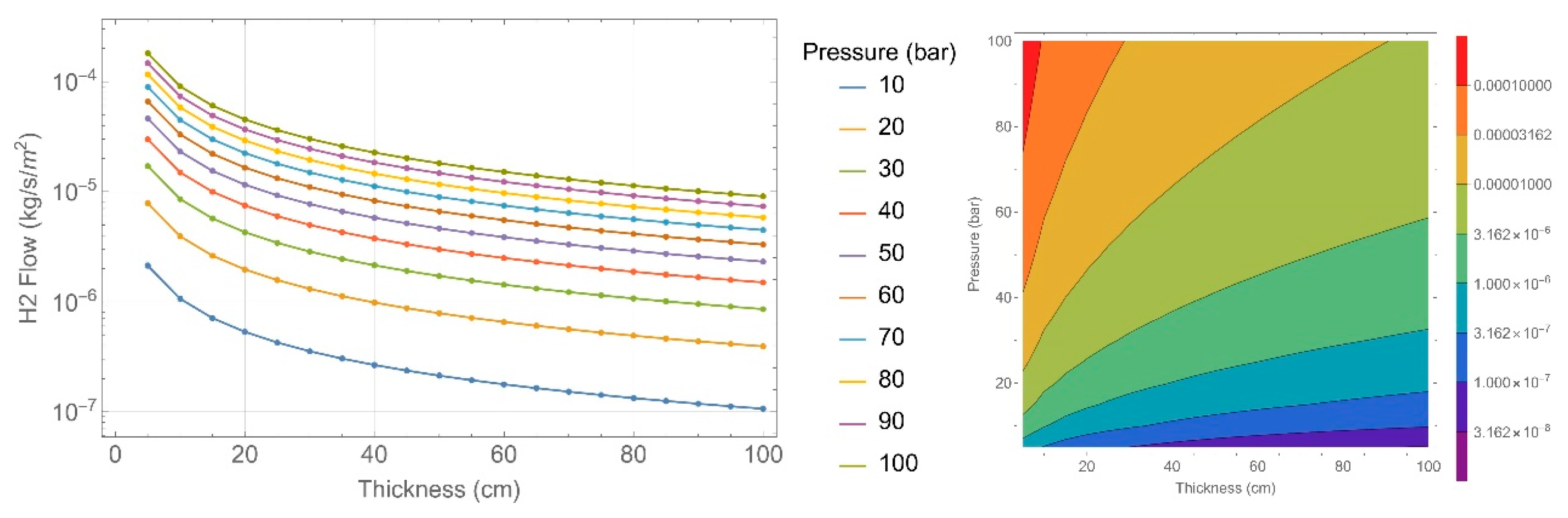
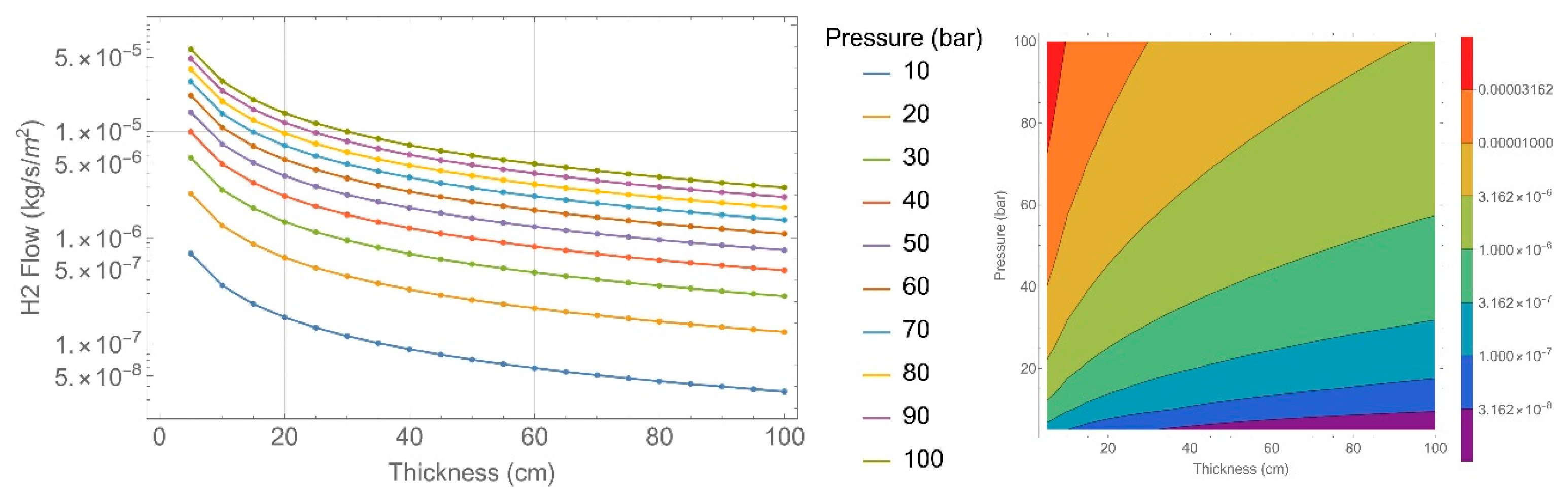
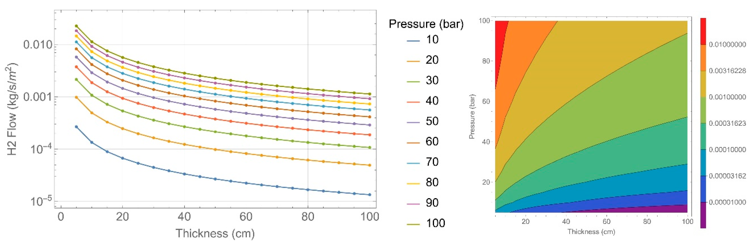
2.4. Permeability Calculation

The permeability coefficient for each specimen tested was calculated. With these values, an adjustment was made, and Equation (4) shows the fit equation obtained:
k = k 1 + b ( p + p a ) 2 = k ( 1 + b P a v )
where:
  • k∞ is the permeability when the pressure is sufficiently high (m2);
  • b is an adjustment parameter, expressed as a non-dimensional parameter;
  • p is the pressure applied during the test (N/m2);
  • pa is the atmospheric pressure (N/m2);
  • Pav is the average pressure (N/m2).
To predict the behavior of a tank wall based on the permeability coefficients obtained with the test, a Finite Element Model (FEM) has been created using the Comsol Multiphysics v. 6.1 program, and the simulation considers the flow of hydrogen in concrete following Darcy’s law. Equations (5) and (6) are used in the FEM model:
t ( ε p p ) + ( p u ) = Q m
u = k μ p
where:
  • εp is the porosity of the concrete, expressed as a non-dimensional parameter;
  • ρ is the gas density (kg/m3);
  • k is the permeability, experimentally obtained (m2);
  • u is the flow velocity of the gas (m/s);
  • µ is the gas viscosity (N·s/m2).
Since one of the main input parameters in the model is permeability, the higher permeability value has been selected for each of the studied conditions. The results of both concretes have been grouped together since their behavioral difference is not significant compared to their moisture content.
A one-dimensional (1D) model has been constructed in order to take advantage of the system’s symmetry, with the objective of replicating the behavior of a wall. The material data incorporated into the Darcy equation have been derived from the results of the tests, as illustrated below. The domain has been divided into elements of approximately 1 mm in size, with quadratic discretization. A parametric study was conducted for each simulated material, in which both the wall thickness (ranging from 5 cm to 100 cm, with a step size of 5 cm) and the internal pressure (ranging from 5 bar to 100 bar, with a step size of 5 bar) were varied. The calculations were performed in a steady state using the PARDISO solver. The model’s output data included the gas flows and the pressure profile within the domain.

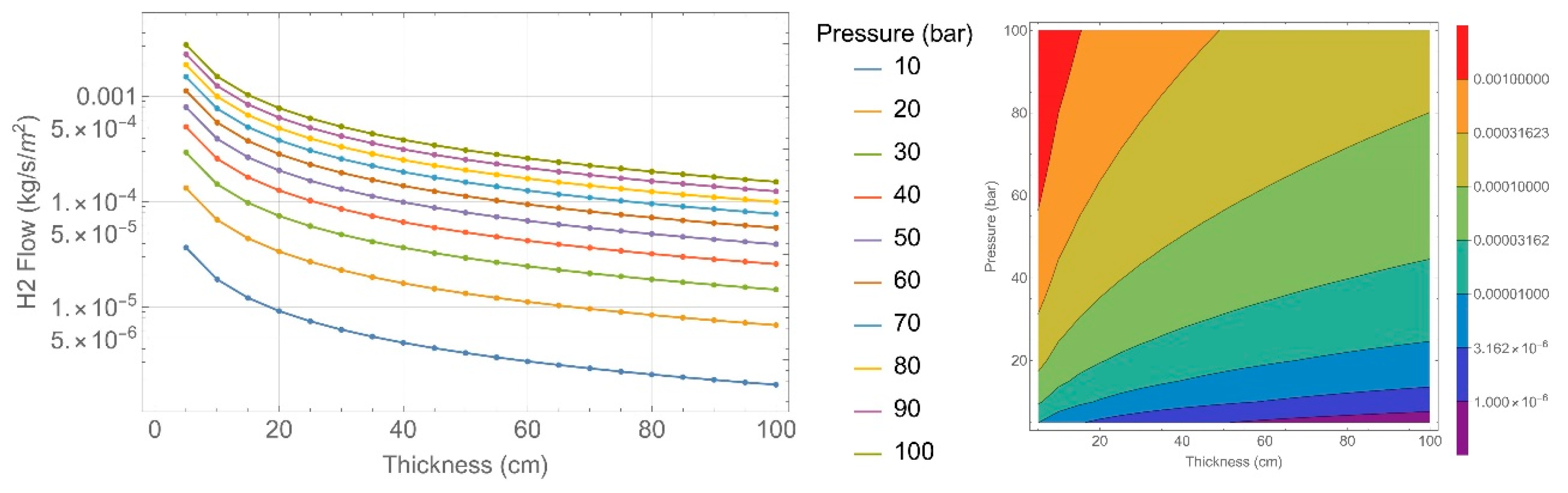
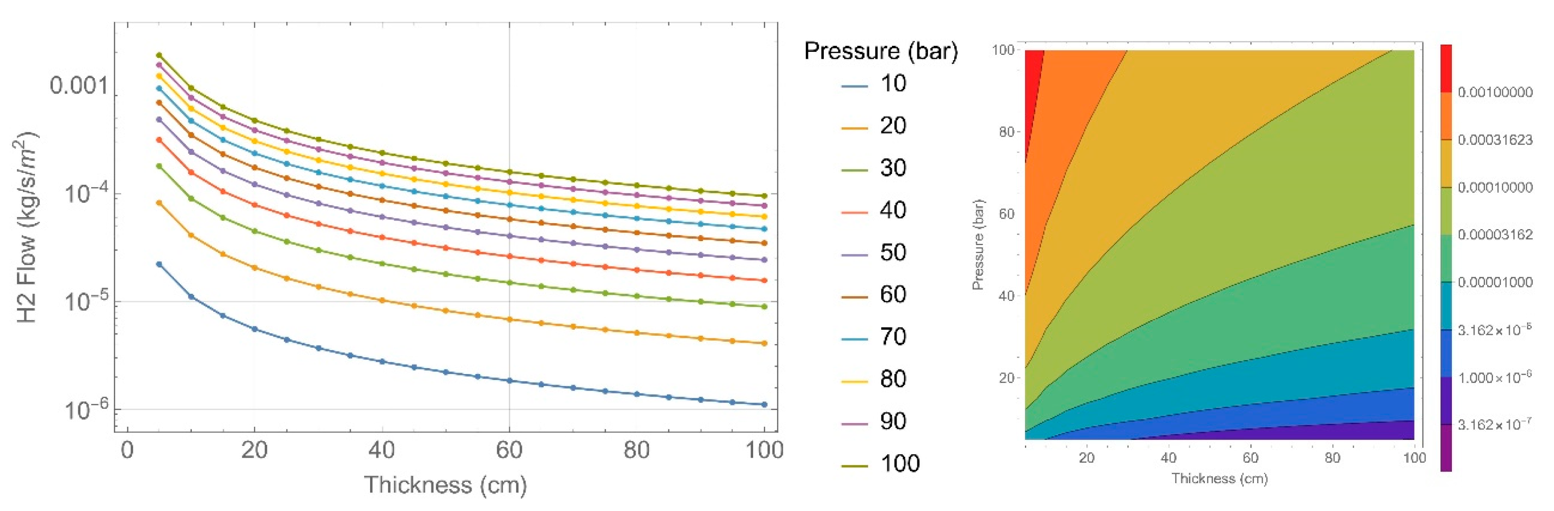
3. Results and Discussion

In light of the results obtained from the laboratory tests, a detailed analysis of the findings is presented below. Figure 1 provides an example of the oxygen permeability coefficient measured for one specific sample. Subsequent figures offer a comprehensive graphical representation of the data collected from all of the samples studied, encompassing the various conditioning states that were applied throughout the experiment. This approach allows for a thorough comparison of the effects observed under different conditions.
Below are the results of the k   obtained for each test condition, grouped by sample type and the presence or absence of cold joints. Equation (4) was used for the fitting process.
Figure 2 and Figure 3 display the values of k∞ for specimens 135 and 151, grouped by the type of gas used in the test and the type of conditioning. No clear trend can be observed based on the type of gas used, but for helium, the highest permeability value is obtained. Concerning the type of conditioning, the highest permeability value is obtained for dry concrete (air-exposed samples), while the lowest value is obtained for saturated concrete. This can be explained by the availability of pores for gas permeation. The trends for the specimens with cold joints are similar, but the values are higher by approximately two orders of magnitude.
The following figures (Figure 4, Figure 5 and Figure 6) show the behavior of both types of concrete exposed to the same conditions, tested with helium. The equations chosen as the most representative for each condition, which is used in the FEM, are also indicated.
In order to use the equations mentioned, it is necessary to make the assumption that hydrogen’s permeability is similar to helium’s. This hypothesis is based on the experimentally obtained results, where no significant influence of the gas on the permeability value has been observed. The effect of humidity or the presence of cold joints is much greater.
The main objective of this study was to simulate the concrete working as a barrier against hydrogen. Therefore, the model determined the amount of gas that would be released into the tank per unit of time and surface area.
To observe the effect of thickness and internal tank pressure, hydrogen flow has been plotted on a logarithmic scale (Figure 7, Figure 8, Figure 9, Figure 10, Figure 11 and Figure 12). The left side of each figure shows a 2D diagram, and the right side depicts the same in a contour plot.
As expected, hydrogen flow increases with the internal gas pressure in the tank and decreases with an increase in the thickness of its wall. Additionally, it increases with a decrease in the moisture content in the concrete and the presence of cold joints, which act as easier and faster pathways for hydrogen.

4. Conclusions

The presented method allows us to quantify the permeability of concrete and provides valuable new insights that are important to consider.
Two types of concrete have been characterized for their gas permeability. The permeability curves have been obtained as a function of the moisture content of the concrete and the presence or absence of cold joints. The obtained results have been incorporated into a finite element model that allowed for the estimation of hydrogen’s permeability based on pressure and concrete thickness. This scenario allows us to estimate the degree of containment provided by concrete alone, without the contribution of steel.
These insights contribute to a better understanding of concrete gas permeability and its implications for enhancing hydrogen containment. As hydrogen becomes an increasingly important energy carrier, ensuring its safe storage and transportation is crucial, and concrete’s role in this regard is better clarified through this study.

Author Contributions

Conceptualization, J.E.T.M. and J.S.M.; Methodology, L.A.A., J.E.T.M. and J.S.M.; Software, L.A.A. and J.S.M.; Validation, J.S.M.; Formal analysis, N.R.R., J.E.T.M., S.C.-P. and J.S.M.; Investigation, L.A.A., N.R.R., J.E.T.M., S.C.-P. and J.S.M.; Resources, R.M.L.C., J.V.-A. and J.D.J.-V.; Data curation, L.A.A. and J.S.M.; Writing—original draft, L.A.A.; Writing—review & editing, J.S.M. and J.V.-A.; Supervision, N.R.R., J.E.T.M., S.C.-P. and J.S.M.; Project administration, J.S.M. All authors have read and agreed to the published version of the manuscript.

Funding

This research received no external funding.

Data Availability Statement

Data is contained within the article.

Acknowledgments

This paper is a part of a research project at the Spanish National Research Council (CSIC). The authors would like to acknowledge Isabel Helices Arcila for their contribution to the experimental process and ACCIONA for supporting the project and providing the concrete samples studied.

Conflicts of Interest

Authors Rosa Maria Lample Carreras, Jose Vera-Agullo and Jose David Jimenez-Vicaria were employed by the company Acciona Construcción, S.A. The remaining authors declare that the research was conducted in the absence of any commercial or financial relationships that could be construed as a potential conflict of interest.

References

  1. Gajda, D.; Lutyński, M. Hydrogen Permeability of Epoxy Composites as Liners in Lined Rock Caverns—Experimental Study. Appl. Sci. 2021, 11, 3885. [Google Scholar] [CrossRef]
  2. Nemanič, V. Hydrogen permeation barriers: Basic requirements, materials selection, deposition methods, and quality evaluation. Nucl. Mater. Energy 2019, 19, 451–457. [Google Scholar] [CrossRef]
  3. Gajda, D.; Lutyński, M. Permeability Modeling and Estimation of Hydrogen Loss through Polymer Sealing Liners in Underground Hydrogen Storage. Energies 2022, 15, 2663. [Google Scholar] [CrossRef]
  4. Amirthan, T.; Perera, M. Underground hydrogen storage in Australia: A review on the feasibility of geological sites. Int. J. Hydrogen Energy 2023, 48, 4300–4328. [Google Scholar] [CrossRef]
  5. Zivar, D.; Kumar, S.; Foroozesh, J. Underground hydrogen storage: A comprehensive review. Int. J. Hydrogen Energy 2021, 46, 23436–23462. [Google Scholar] [CrossRef]
  6. Peng, T.; Wan, J.; Liu, W.; Li, J.; Xia, Y.; Yuan, G.; Jurado, M.J.; Fu, P.; He, Y.; Liu, H. Choice of hydrogen energy storage in salt caverns and horizontal cavern construction technology. J. Energy Storage 2023, 60, 106489. [Google Scholar] [CrossRef]
  7. Harris, A.; Atkinson, A.; Claisse, P. Transport of gases in concrete barriers. Waste Manag. 1992, 12, 155–178. [Google Scholar] [CrossRef]
  8. Kim, J.; Kim, J.; Jung, H.; Ha, J.-C.; Kim, E.-H. Gas threshold pressure and gas permeability of silo concrete specimens for a low- and intermediate-level waste disposal facility in Korea. Ann. Nucl. Energy 2013, 55, 1–8. [Google Scholar] [CrossRef]
  9. Scott, D.S.; Dullien, F.A.L. Diffusion of ideal gases in capillaries and porous solids. AIChE J. 1962, 8, 113–117. [Google Scholar] [CrossRef]
  10. Hamami, A.; Turcry, P.; Aït-Mokhtar, A. Influence of mix proportions on microstructure and gas permeability of cement pastes and mortars. Cem. Concr. Res. 2012, 42, 490–498. [Google Scholar] [CrossRef]
  11. Heede, P.V.D.; Gruyaert, E.; De Belie, N. Transport properties of high-volume fly ash concrete: Capillary water sorption, water sorption under vacuum and gas permeability. Cem. Concr. Compos. 2010, 32, 749–756. [Google Scholar] [CrossRef]
  12. Zhang, D.; Li, K. Concrete gas permeability from different methods: Correlation analysis. Cem. Concr. Compos. 2019, 104, 103379. [Google Scholar] [CrossRef]
  13. Issaadi, N.; Hamami, A.; Belarbi, R.; Aït-Mokhtar, A. Experimental assessment of the variability of concrete air permeability: Repeatability, reproducibility and spatial variability. Energy Procedia 2017, 139, 537–543. [Google Scholar] [CrossRef]
  14. Boumaaza, M.; Huet, B.; Pham, G.; Turcry, P.; Aït-Mokhtar, A.; Gehlen, C. A new test method to determine the gaseous oxygen diffusion coefficient of cement pastes as a function of hydration duration, microstructure, and relative humidity. Mater. Struct. Mater. Constr. 2018, 51, 51. [Google Scholar] [CrossRef]
  15. Lamouchi, T.; Levasseur, S.; Potier, L.; Dubois, T.; Skoczylas, F. About Gas Permeability and Diffusion through Concrete. Mater. Proc. 2023, 13, 42. [Google Scholar] [CrossRef]
  16. Chao, Z.; Gong, B.; Yue, W.; Xu, X.; Shi, D.; Yang, C.; Hu, T. Experimental study on stress-dependent gas permeability and porosity of artificially cracked cement mortar. Constr. Build. Mater. 2022, 359, 129290. [Google Scholar] [CrossRef]
  17. Qian, R.; Liu, C.; Liu, G.; Liu, Z.; Pang, B.; She, W.; Zhang, Y. Effects of various inlet-gas mediums on apparent permeability of concrete under steady-state flow: Comparison between carbon-dioxide and oxygen. Cem. Concr. Compos. 2021, 119, 103995. [Google Scholar] [CrossRef]
  18. Rosti, M.E.; Cortelezzi, L.; Quadrio, M. Direct numerical simulation of turbulent channel flow over porous walls. J. Fluid Mech. 2014, 784, 396–442. [Google Scholar] [CrossRef]
  19. Zhang, Y.; Li, H.; Abdelhady, A.; Yang, J.; Wang, H. Effects of specimen shape and size on the permeability and mechanical properties of porous concrete. Constr. Build. Mater. 2021, 266, 121074. [Google Scholar] [CrossRef]
  20. Abbas, A.; Carcasses, M.; Ollivier, A.-P. Gas permeability of concrete in relation to its degree of saturation. Mater. Struct./Mater. Constr. 1999, 32, 3–8. [Google Scholar] [CrossRef]
  21. Jooss, M.; Reinhardt, H.W. Permeability and diffusivity of concrete as function of temperature. Cem. Concr. Res. 2002, 32, 1497–1504. [Google Scholar] [CrossRef]
  22. Andrade, C.; Bettencourt-Ribeiro, A.; Buenfeld, N.R.; Carcasses, M.; Carino, N.J.; Ehrenberg, F.; Ewertson, C.; Garbocczi, E.; Geiker, M.; Gjorv, O.E.; et al. Permeability of Concrete as a Criterion of its Durability. Mater. Struct. 1999, 32, 174–179. [Google Scholar]
  23. Yiğiter, H.; Yazıcı, H.; Aydın, S. Effects of cement type, water/cement ratio and cement content on sea water resistance of concrete. Build. Environ. 2007, 42, 1770–1776. [Google Scholar] [CrossRef]
  24. Chen, X.; Wu, S. Influence of water-to-cement ratio and curing period on pore structure of cement mortar. Constr. Build. Mater. 2013, 38, 804–812. [Google Scholar] [CrossRef]
  25. Illangakoon, G.B.; Asamoto, S.; Nanayakkara, A.; Trong, L.N. Concrete cold joint formation in hot weather conditions. Constr. Build. Mater. 2019, 209, 406–415. [Google Scholar] [CrossRef]
  26. Yoo, S.-W.; Kwon, S.-J. Effects of cold joint and loading conditions on chloride diffusion in concrete containing GGBFS. Constr. Build. Mater. 2016, 115, 247–255. [Google Scholar] [CrossRef]
  27. Kishen, J.C.; Rao, P.S. Fracture of cold jointed concrete interfaces. Eng. Fract. Mech. 2007, 74, 122–131. [Google Scholar] [CrossRef]
  28. UNE 83981; Concrete Durability. Test Methods. Determination to Gas Permeability of Hardened Concrete. AENOR: Madrid, Spain, 2008.
  29. Jung, J.K.; Lee, J.H.; Jang, J.S.; Chung, N.K.; Park, C.Y.; Baek, U.B.; Nahm, S.H. Characterization technique of gases permeation properties in polymers: H2, He, N2 and Ar gas. Sci. Rep. 2022, 12, 3328. [Google Scholar] [CrossRef] [PubMed]
  30. Care, S.; Derkx, F. Determination of relevant parameters influencing gas permeability of mortars. Constr. Build. Mater. 2011, 25, 1248–1256. [Google Scholar] [CrossRef]
  31. Dutzer, V.; Dridi, W.; Poyet, S.; Le Bescop, P.; Bourbon, X. The link between gas diffusion and carbonation in hardened cement pastes. Cem. Concr. Res. 2019, 123, 105795. [Google Scholar] [CrossRef]
  32. UNE 83966; Concrete Durability. Test Methods. Conditioning of Concrete Test Pieces for the Purpose of Gas Permeability and Capilar Suction Tests. AENOR: Madrid, Spain, 2008.
  33. UNE-EN 12390-2; Testing Hardened Concrete—Part 2: Making and Curing Specimens for Strength Tests. AENOR: Madrid, Spain, 2020.
  34. UNE-EN 12390-19; Testing of Hardened Concrete—Part 19: Determination of Electrical Resistivity. AENOR: Madrid, Spain, 2023.
  35. UNE-EN 12504-4:2022; Testing Concrete in Structures—Part 4: Determination of Ultrasonic Pulse Velocity. AENOR: Madrid, Spain, 2022.
  36. Franco-Luján, V.A.; Maldonado-García, M.A.; Jiménez-Quero, V.G.; Montes-García, P. Reliability of electrical resistivity on the long-term monitoring of concrete. Results Eng. 2023, 18, 101154. [Google Scholar] [CrossRef]
  37. Aragoncillo, A.M.M.; Cleary, D.B.; Lomboy, G.R. Estimating the permeability of porous aggregate concretes using electrical resistivity based tests. Constr. Build. Mater. 2023, 364, 129909. [Google Scholar] [CrossRef]
  38. Azarsa, P.; Gupta, R. Electrical Resistivity of Concrete for Durability Evaluation: A Review. Adv. Mater. Sci. Eng. 2017, 2017, 8453095. [Google Scholar] [CrossRef]
  39. Cheytani, M.; Chan, S. The applicability of the Wenner method for resistivity measurement of concrete in atmospheric conditions. Case Stud. Constr. Mater. 2021, 15, e00663. [Google Scholar] [CrossRef]
  40. Fitzka, M.; Karr, U.; Granzner, M.; Melichar, T.; Rödhammer, M.; Strauss, A.; Mayer, H. Ultrasonic fatigue testing of concrete. Ultrasonics 2021, 116, 106521. [Google Scholar] [CrossRef] [PubMed]
  41. Moura, M.A.D.N.; Moreno, A.L.; Ferreira, G.C.d.S. Ultrasonic testing on evaluation of concrete residual compressive strength: A review. Constr. Build. Mater. 2023, 373, 130887. [Google Scholar] [CrossRef]
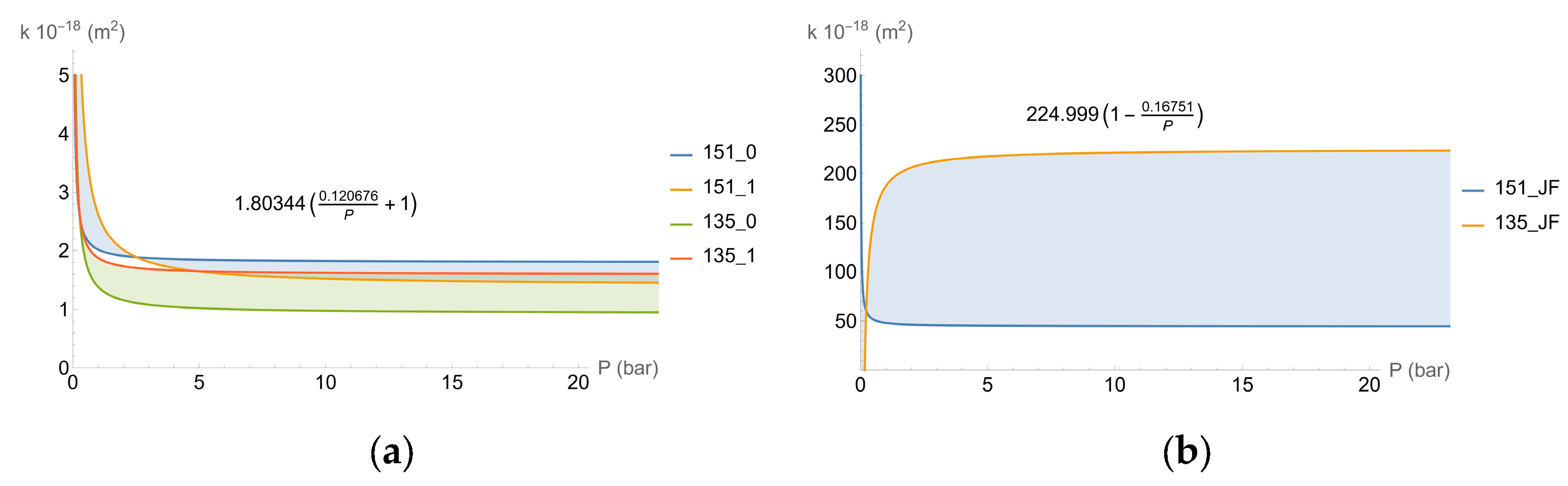
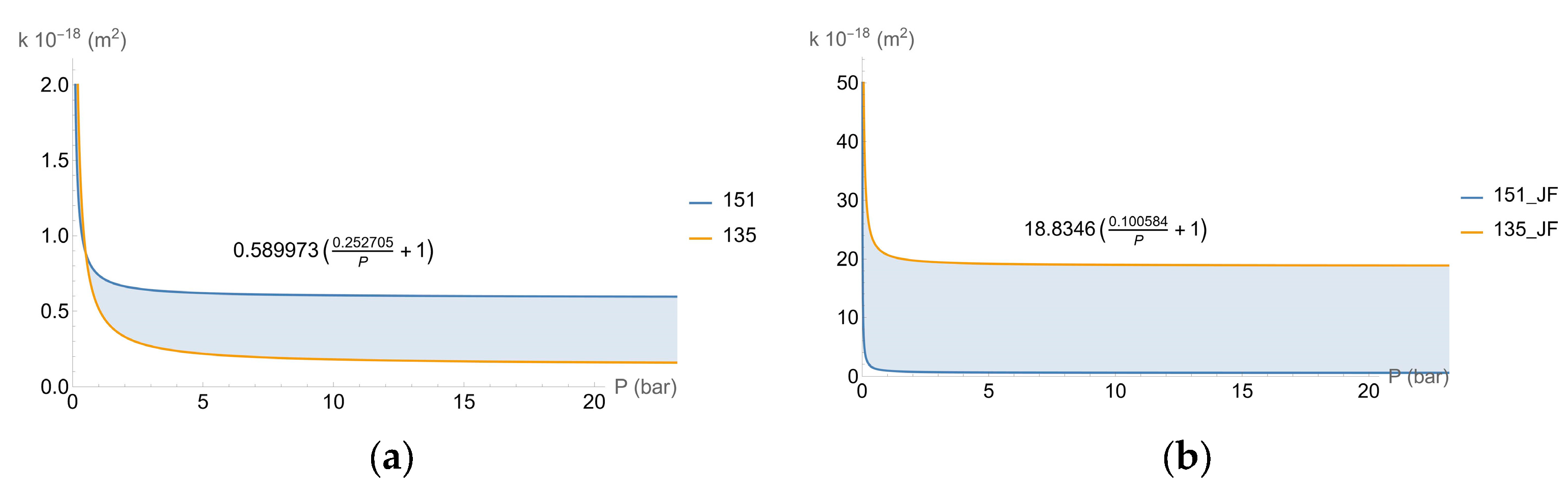
Figure 1. An example of one of the samples measured (O2)—151 concrete, without cold joints, exposed to air.
Applsci 14 06408 g001
Figure 2. Permeability without cold joint: (a) sample 135; (b) sample 151.
Applsci 14 06408 g002
Figure 3. Permeability with cold joint: (a) sample 135; (b) sample 151.
Applsci 14 06408 g003
Figure 4. Air-exposed concrete: (a) permeability of specimens without cold joint; (b) permeability of specimens with cold joint.
Applsci 14 06408 g004
Figure 5. 65% RH: (a) permeability of specimens without cold joint; (b) permeability of specimens with cold joint.
Applsci 14 06408 g005
Figure 6. Saturated: (a) permeability of specimens without cold joint; (b) permeability of specimens with cold joint.
Applsci 14 06408 g006
Figure 7. Hydrogen flow in air-exposed specimens.
Applsci 14 06408 g007
Figure 8. Hydrogen flow in 65% RH-conditioned specimens.
Applsci 14 06408 g008
Figure 9. Hydrogen flow in saturated specimens.
Applsci 14 06408 g009
Figure 10. Hydrogen flow in air-exposed specimens with cold joints.
Applsci 14 06408 g010
Figure 11. Hydrogen flow in 65% RH-conditioned specimens with cold joints.
Applsci 14 06408 g011
Figure 12. Hydrogen flow in saturated specimens with cold joints.
Applsci 14 06408 g012
Table 1. Concrete characteristics.
Concrete Characteristics135 Specimens151 Specimens
TypeConcrete for precast elements with high early-age strengthsSlip-form concrete
CementCEM III/A 42.5 N/SRCCEM II/A-S 42.5 R/SRC
Slump test18 cm22 cm
Cement425 kg/m3385 kg/m3
W/C ratio0.350.40
Density2383 kg/m32323 kg/m3
28-day compressive strength62 MPa47 MPa
Disclaimer/Publisher’s Note: The statements, opinions and data contained in all publications are solely those of the individual author(s) and contributor(s) and not of MDPI and/or the editor(s). MDPI and/or the editor(s) disclaim responsibility for any injury to people or property resulting from any ideas, methods, instructions or products referred to in the content.

