Article

Inconel 718 Hybrid Laser-Based Directed Energy Deposition and Wrought Component Characterization through Small Punch Tests

by
Ibon Miguel
1,
Garikoitz Artola
1,
Jon Iñaki Arrizubieta
2,
Ana Isabel Fernández-Calvo
1 and
Carlos Angulo
2,*
1
AZTERLAN, Basque Research and Technology Alliance (BRTA), 48200 Durango, Spain
2
Department of Mechanical Engineering, University of the Basque Country (UPV/EHU), 48013 Bilbao, Spain
*
Author to whom correspondence should be addressed.
Appl. Sci. 2024, 14(15), 6420; https://doi.org/10.3390/app14156420
Submission received: 19 June 2024 / Revised: 11 July 2024 / Accepted: 19 July 2024 / Published: 23 July 2024
(This article belongs to the Special Issue Metals and Materials: Science, Processes and Applications)

Abstract

:

Featured Application

Assessment of the mechanical properties of the weld lines between wrought and laser-based directed energy deposition overlays.

Abstract

The combination of wrought materials and laser-based directed energy deposition (DED-LB) is being increasingly used for manufacturing new and repairing old or damaged components in several industries. Aerospace components made of Inconel 718 featuring small-thickness DED-LB buildups are a remarkable example of such a combination due to the high added value it brings. Despite that these are usually critical components, the miniature testing methods to assess the local mechanical properties in the buildup area are not fully developed. This work contributes to this miniature testing development with an improvement of the small punch testing (SPT) technique for measuring the mechanical properties of the weld line between the DED-LB and the wrought substrate. A new criterion for weld line positioning in the SPT specimens is proposed and applied on samples of hybrid wrought/DED-LB Inconel 718. The results of positioning the weld line at the necking site of the SPT specimen show that the proposed approach is valid for assessing the properties of the transition zone between the wrought and additive states. For the specific conditions tested and taking the wrought material as a reference, the strength of the Inconel 718 drops 10% in the weld line and 20% in the buildup.

1. Introduction

The aerospace sector is speeding up the adoption of metal additive manufacturing technologies as such technologies are becoming more capable of satisfying current demand. As described in a recent review on the trends of laser welding and additive manufacturing by Malikov et al. [1], the use of additive technologies in aerospace requires ensuring the reliability, durability, and compatibility of the components. It must also result in a benefit in terms of the manufacturing time of parts or the buy-to-fly ratio. This ratio has been associated with the sustainability of the aerospace industry in two further recent reviews from Rodrigues et al. [2] and Singh et al. [3] on the role of additive manufacturing on this specific subject. Sustainability is considered a major driving force for introducing additive manufacturing parts in aerospace. This includes the adoption of hybrid parts, which are produced by employing an additive process on a forged, rolled, or cast precursor of the final product. An increased material yield, a reduction in the machine time, and chip removal are further advantages when using hybrid components. The most beneficial aspects of wrought and cast materials can be combined with the advantages of additive manufacturing. This has led to multiple hybrid manufacturing approaches, as shown in the work by Sefene et al. [4]. This review shows that forged, stamped, or cast shapes cannot be normally overlaid with powder bed fusion (PBF) additive technologies; hybridization preferably implies the use of laser-based directed energy deposition (DED-LB) or wire arc additive manufacturing (WAAM). The former allows for better dimensional accuracy and less heat input being thus preferable for repair and maintenance works.
The interest in improving the fly-to-buy ratio is even more evident when high-added-value alloys are involved. A representative example of this interest is the work by Srinivasan et al. [5] that explains the increasing interest in DED-LB with alloys such as CSU-B1, Hastelloy C, Haynes 282, Haynes 282, IC10, Rene 104, Inconel 100, Inconel 625, and Inconel 718. The last of the alloys, Inconel 718, has been often studied by combining wrought/cast and cladded materials in a single part. This hybridization has been promoted by the rise of DED-LB technology and the need to repair damaged parts with other welding technologies. On the DED-LB side, the repair of Inconel 718 components is a topic of interest that has promoted the study of microstructural evolutions and the processing parameters or postprocessing strategies, as shown in the works by Zhang et al. [6], Ramiro et al. [7], and Kang et al. [8], respectively. On the side of other welding technologies, similar interests are found. Kang et al. chose to study the cracking susceptibility [9], Fisk et al. [10] focused on the welding process and the post-weld heat treatment, and Wu et al. [11] aimed for the microstructure and mechanical properties. In this selection of works which are representative of the recent literature in the subject, microstructural analyses and mechanical property assessments can be found for both the deposited material and the base material. However, the mechanical properties of the transition line between the wrought and additively deposited materials have not been thoroughly studied.
To conduct this type of research, targeted at a very short transition region between two materials, miniaturized specimen testing can be used. This type of testing allows for high spatial resolution in specimen extraction, and it is finding growing use in detailed studies of joints made of a variety of metals. Ma et al. [12] employed miniaturized tensile testing specimens to characterize a joint area between forged Ti-6Al-4V and a 60 × 60 × 20 mm3 DED-LB overlay [13]. The size of the sample specimens in this approach was 45 × 10 × 2 mm3, while the volume of interest was of 10 × 2 × 0.5 mm3.
The advantages of this testing approach explain why other authors have preferred further reduced sampling techniques. Zu et al. [13], García-Blanco et al. [14], and Taheri [15] employed small punch testing (SPT) specimens dimensioned at 10 × 10 × 0.5 mm3 to assess the mechanical properties of arc-welded X60 steel, Co alloy DED-LB overlays on rolled 316L stainless steel, and Inconel 713 overlays on cast Inconel 713, respectively. In these three cases, the transition between the deposited metal and the base metal was not perpendicular to the loading. As a consequence, these tests did not assess the junction area strength itself, but measured the average of the heat-affected zone (HAZ) and the deposited metal, which varied depending on the specimen dissection position. Similar drawbacks were found in the works by Kim et al. [16], Serre et al. [17], and Li et al. [18]. In these three cases, the interface was positioned along the diameter of the SPT specimen for Inconel 713/Inconel 713 arc deposition, P91/316L steel arc depositions, and W/Ta diffusion clads, respectively. During the bulging of the SPT, the actual load in a diameter-spanning junction area is shared equally by the HAZ and the deposited material. However, none of the approaches in the aforementioned studies loaded the interface perpendicularly; therefore, this gap in the literature highlights the need for an improved SPT configuration to test the mechanical properties of transition interfaces.
Despite the difficulties found in properly aligning the load and the weld line, there is still interest in using SPT because the reduction in the sampling volume when comparing miniature tensile testing [12] to SPT [13,14,15,16,17,18] is 18 to 1. Furthermore, the study from Courtright et al. [19] specifically compared the use of tensile testing and SPT for laser-based powder bed fusion (PBF-LB), where they found the cost ratio of tensile-to-SPT to be in the range of 100 to 1. Thus, among the many options for miniature testing, the SPT methodology shows great advantages when studying small areas of interest in expensive alloys and technologies, such as Inconel 718 and products from metal additive manufacturing. This explains why even though more traditional tensile testing is used for mechanical property research with Inconel 718 via PBF-LB and DED-LB, works employing SPT are also growing.
It is noticeable that tensile testing is employed preferably for the comparison of properties obtained on Inconel 718 when using different manufacturing technologies. Lu et al. [20] explored differences in the room temperature tensile properties of PBF-LB, DED-PB, and cast and wrought Inconel 718. The work of Arrizubieta et al. [21] complements this scope by comparing the results obtained when employing both powder- and wire-fed DED-LB. On the other hand, Trosch et al. [22] compared the PBF-LB, casting, and forging tensile properties at different temperatures.
Regarding the above-referenced works employing SPT with Inconel 718, Courtright et al. and Lancaster [19,23] focused on comparing SPT with tensile testing for their use with PBF-LB-manufactured Inconel 718 at room temperature, while Wang et al. and Peng et al. [24,25] employed the SPT method to assess the mechanical performance of PBF-LB Inconel 718 at high temperatures.
Considering the subjects described above, this current work fills two gaps in the published literature: on the one hand, it employs the SPT method to study the mechanical behaviour of DED-LB Inconel 718, which has previously only been used for PBF-LB, and, on the other hand, it proposes an adaptation of the weld line position in SPT specimens to overcome the drawbacks found in previous SPT approaches that were aimed at assessing interfacial mechanical properties.

2. Materials and Methods

The Inconel 718 nickel-based alloy was selected for the study, which is widely employed in jet engines thanks to its outstanding corrosion resistance and good mechanical properties at high temperatures. There are three reasons for the material choice: the availability of the materials both in forged and powder format, the amount of the literature for consultation, and the high interest in the DED-LB repair and hybrid manufacture of Inconel 718 gas turbine/jet engine components. Additionally, the Inconel 718 is an expensive material, in which any saving results in reducing the process’ expenses, as well as lowering the environmental impact of the manufacturing process. The base material employed to manufacture the specimens was a 60 mm-diameter and 20 mm-high cylindrical disk obtained from wrought Inconel 718. The filler material for DED-LB in the specimen manufacture was a gas-atomized Inconel 718 powder. The upper and lower faces of the base-forged material were ground to ensure substrate flatness and cleaned with acetone to remove any coolant residues that could have affected the DED-LB tests.
Both the base alloy for the substrate and DED-LB overlay were analyzed by spark emission spectrometry using the internal method based on ASTM E1086 [26]. As mentioned below, DED-LB layers were used to build the specimens up to a thickness of 12 mm. The chemical composition of the deposited material was measured in a cylinder extracted at about half the height of the deposited layer, in the same position as the SPTs in the deposited area. The chemical composition of the Ni-base powder was also analyzed by inductively coupled plasma emission spectrometry, which is an internal method based on the UNE-EN 10361 standard [27]. The carbon content was measured using an automatic infrared analyzer and the followed procedure was based on ASTM E1019 [28] for the three material conditions: forged, DED-LB, and powder material.
After sticking the dispersed powder particles onto a flat surface, the powder was characterized by field emission scanning electron microscopy (FESEM) with a ZEISS Ultra Plus microscope (Carl Zeiss AG, Oberkochen, Germany). The particle size distribution of the powder was determined using the ImageJ (1.53 e) software. Circularity was defined as 4πA / P , where A and P are the area and the perimeter of the powder particle, respectively. An energy-dispersive X-ray (EDX) spectroscopy analysis was conducted with a field emission scanning electron microscope to determine the mapping of alloying elements.
Prior to manufacturing the hybrid specimens, DED-LB process adjustment tests were performed in a five-axis laser center coupled with a 1 kW continuous maximum power laser from Coherent (Saxonburg, PA, USA). An in-house manufactured coaxial nozzle was employed (Figure 1) and argon with 99.99% purity was employed as the drag and protective gas with 5 L/min and 15 L/min flow rates, respectively. The focal plane was situated at a 15 mm distance from the nozzle tip, where the laser was focused at a 1.5 mm circular spot.
Powder was supplied into the nozzle through a Sulzer Metco Twin 10c gravimetric powder feeder (Pfäffikon, Switzerland) with heated hoppers, which were warmed up to 60 °C prior to the tests to remove any moisture from the powder. The powder feeder was calibrated for the selected material and the relation between the rotation speed and the feed rate was defined via Equation (1), where N is the feeder rotation speed in revolutions per minute and Q is the outcome feed rate in grams per minute:
Q = 0.3442·N + 0.1555
The attenuation of laser power through the employed optical systems was measured by a photodiode cell, and the laser was calibrated to provide the desired real power. Two averaging sequences were performed and in each the energy consumption was measured in ascending and descending orders throughout the power range of the laser. Therefore, four measurements, 60 s duration each, were carried out for every nominal laser power value. In Figure 2, the relation between the nominal and real laser powers is provided, where, approximately, a constant 7% loss is detected throughout the studied range. In the experimental tests carried out in the present research, this power loss is taken into account and, therefore, the provided laser power values refer to the real laser power.

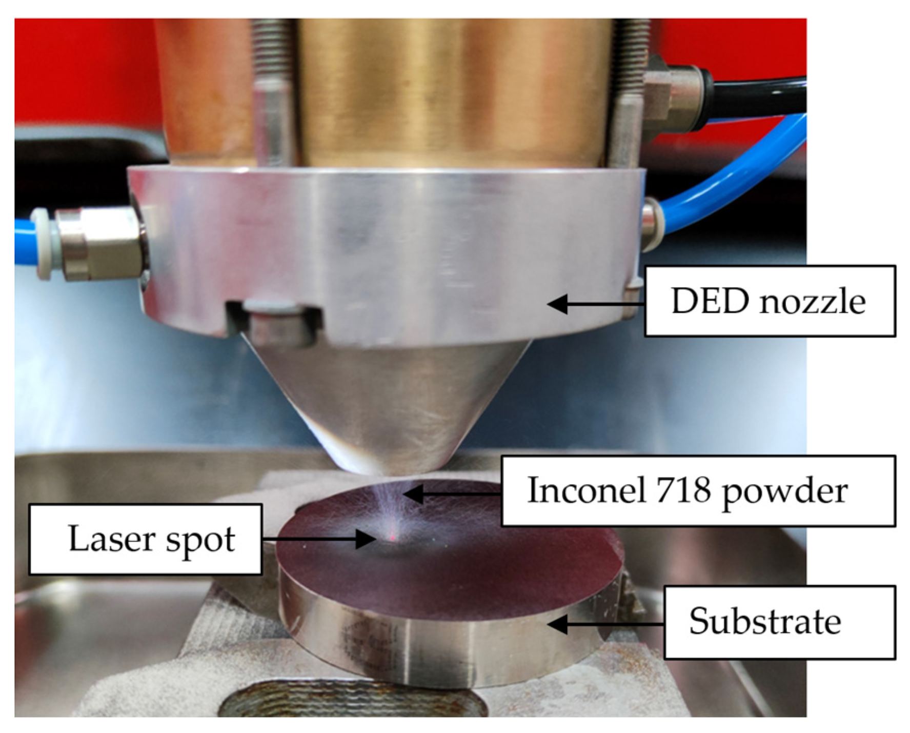
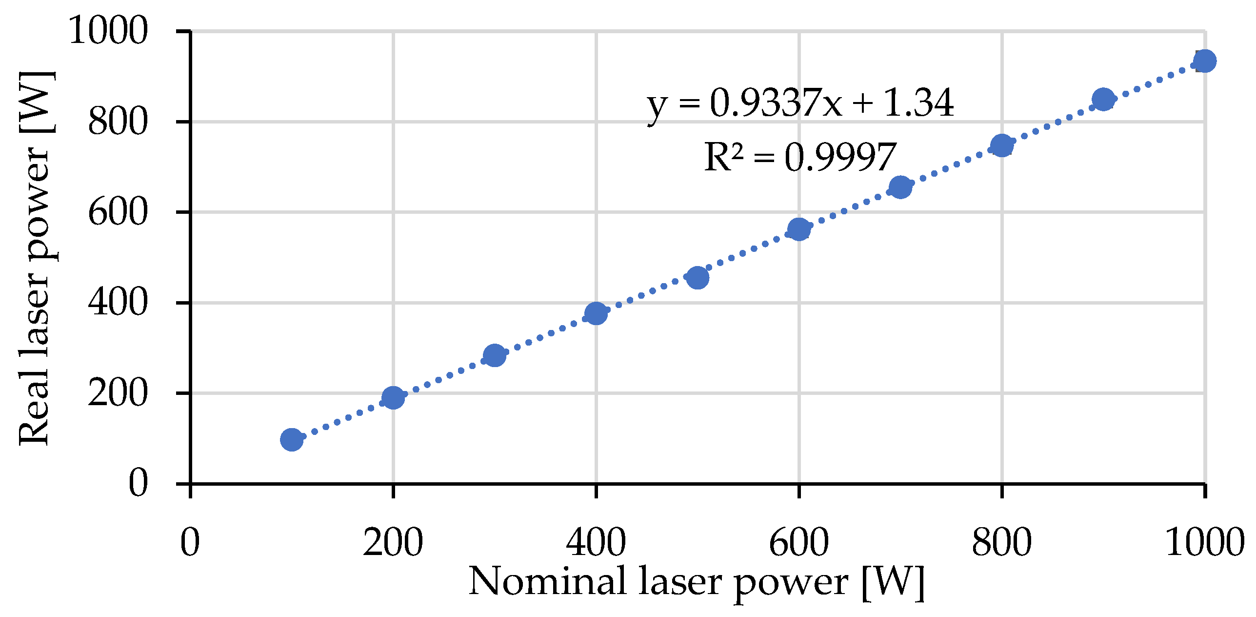
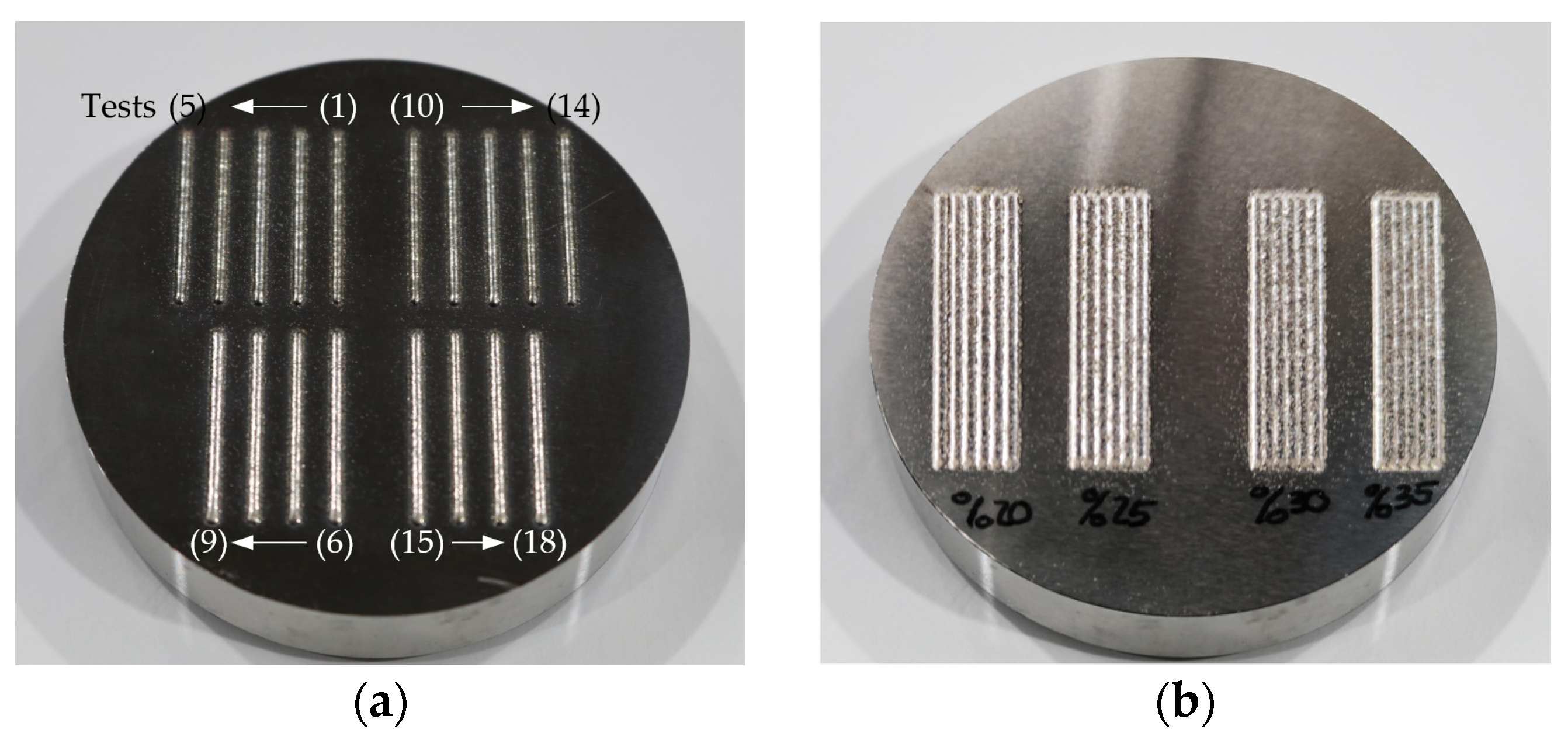
2.1. Optimal Process Parameter Definition

Before manufacturing the SPT coupons, the DED-LB process parameters needed to be defined. For this purpose, a suite of experiments was run with 18 tests, where we varied the laser power (500, 550, and 600 W), machine feed rate (500, 525, and 550 mm/min), and powder mass rate (5.5–6.0 g/min). The test conditions are summarized in Table 1 and the deposited clads are shown in Figure 3a. Individual tests specimens were cross-sectioned and prepared following the appropriate metallographic procedure. Three sections were analyzed for each test. Cross-sections were polished with a Forcipol 102 Metkon automatic polisher (Bursa, Turkey) and etched using Kalling’s 2 reagent to reveal the microstructure of the material. The microstructure and quality of the individual clads, as well as the deposited coatings, were evaluated under an optical microscope, a Leica DCM 3D (Wetzlar, Germany).
Once the optimal parameters were defined for single-clad deposition, the overlap distance between two adjacent clads was defined as a function of the clad width percentage. Overlap values of 20%, 25%, 30%, and 35% were tested and the stability of the deposited five-clad layer was analyzed. Similar to the single-clad tests, three sections for each overlap value were analyzed as well.

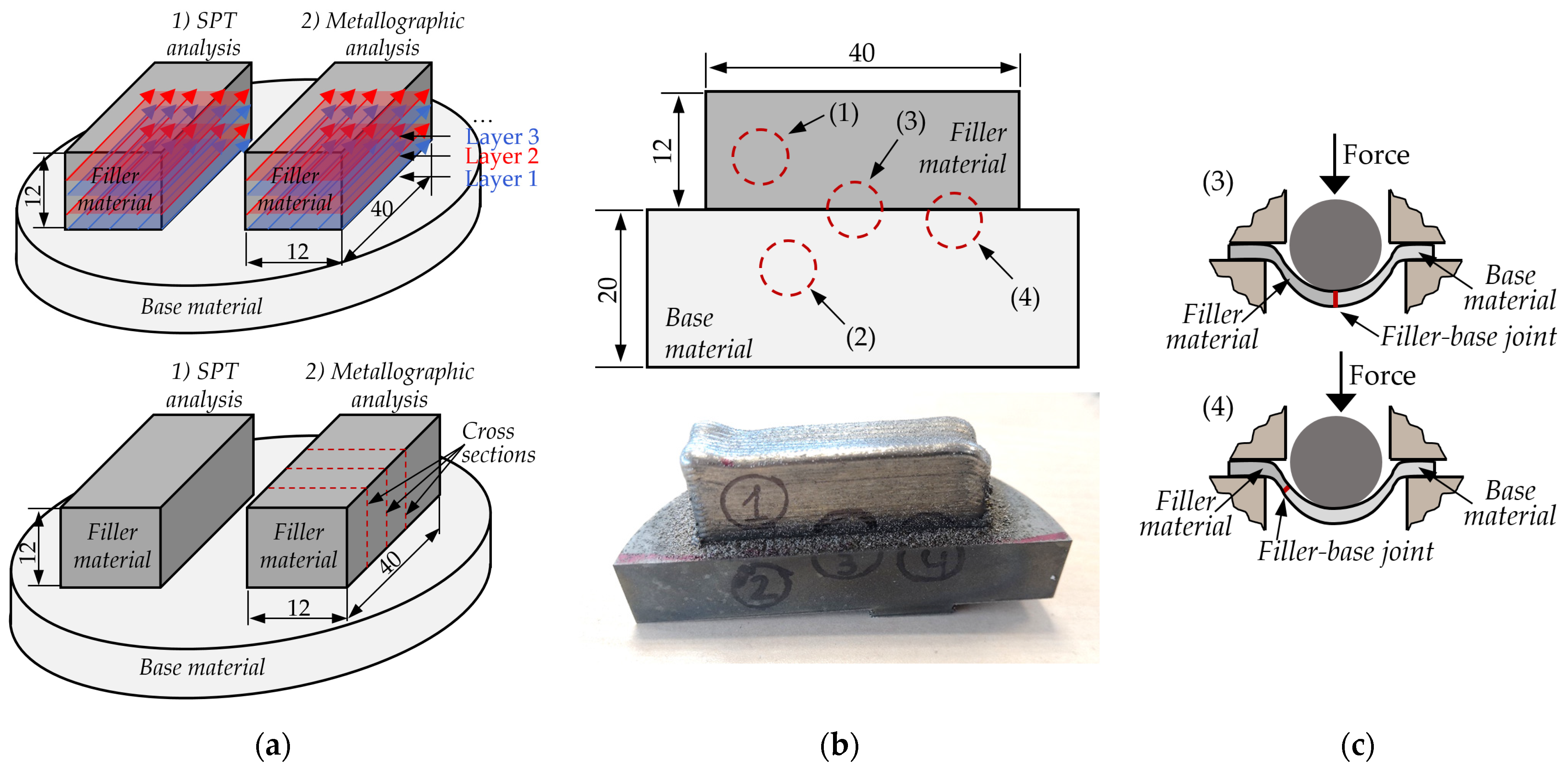
2.2. Hybrid Coupon Manufacturing for Small Punch Testing Characterization

Once the optimal process parameters were selected, the coupons used for SPT specimen dissection were manufactured. For this purpose, the same wrought Inconel 718 base was employed, which had a 60 mm diameter and 20 mm height. Centered on the base material, two parallelepipeds of 40 mm length, 12 mm width, and 12 mm height were deposited using a longitudinal deposition strategy, see Figure 4a. The first parallelepiped was employed for the SPT, whereas the second was employed for the metallographic analysis of the deposited material. For this purpose, three transversal cuts along the longitudinal direction were made.
Within the parallelepiped, four locations were analyzed through SPT sampling (base and filler) and two transition positions contained the interface. The first one corresponded to 100% filler material, the second to 100% wrought base material, the third was centered on the joint between the filler DED-LB and wrought base materials, and the fourth was situated to test the joint in the necking zone (20% filler material and 80% base material). See Figure 4b for further details regarding the analyzed situations. Using wire electric discharge machining (w-EDM), four 8 ± 0.01 mm-diameter and 12 mm-long cylinders were cut. In a second step, again using w-EDM, three disks 0.6 mm-thick were cut from each cylinder. Prior to SPT, each disk was ground and polished down to a 0.5 ± 0.005 mm thickness ensuring that the roughness, Ra, was below 0.25 µm. In Figure 4c, the interface location (filler–base joint) in the SPT for the specimens containing a transition from wrought to DED-LB material (positions 3 and 4) is highlighted.

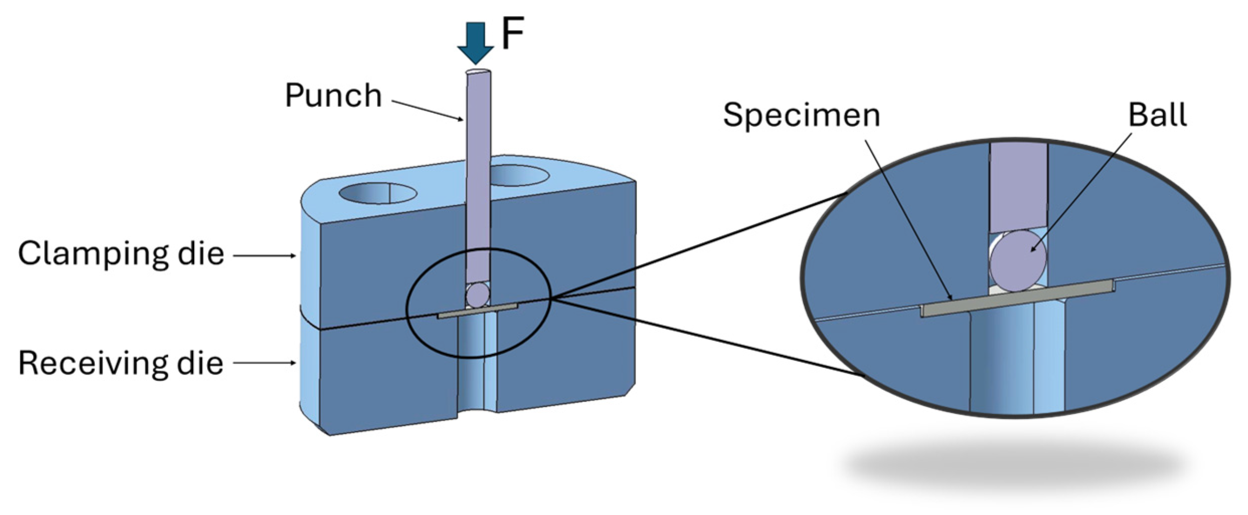
2.3. Small Punch Test Procedure

After grinding and polishing the three samples per condition described above, the diameter, thickness, and roughness were measured to ensure that the testing standard ASTM E3205 [29] was satisfied. For the diameter, two measurements were taken 90° apart and the thickness was measured at four positions around the perimeter at 90° intervals and in the middle.
To perform the SPT, each specimen was positioned in the receiving die located centrally below the punch and clamped with a clamping die. For this purpose, four M5 screws were used, where a torque of 10 Nm was applied to each. Finally, the ball and the punch were inserted into the clamping die centered on the top face of the specimen.
In total, 12 SPT samples were tested with a universal testing machine (Zwick All Round Z100, Zwick, Ulm, Germany), coupling a load cell of 5 kN and a custom designed SPT tool like the one shown in Figure 5. The specimens were tested until failure at a constant displacement rate of 0.5 mm/min. The characteristic geometrical dimensions of the SPT tool are described in [30] and briefly summarized here: the diameter of the receiving die was 32 mm, the diameter of the receiving die was 4 mm, the punch diameter was 2.5 mm, the corner radius of the receiving die was 0.2 mm, and a ball of 2.5 mm diameter with a hardness of 55 HRC was employed to force the central portion of the specimen through the hole in the receiving die.
During the test, the force and the displacement were measured, obtaining for each specimen a characteristic force–displacement (Fv) curve. From these curves, the elastoplastic transition force, Fe, the maximum force, Fm, and the displacement corresponding to the maximum force, um, were obtained.
Finally, calculations were performed to estimate the yield strength (Rp0.2) and tensile strength (Rm), both in MPa, from the characteristic values of the SPTs and the initial thickness. The formulas proposed in ASTM E3205 are
R p 0.2 = β R p 0.2   ·   F e h 0 2   ,
R m = β R m · F m h 0 · u m   ,
where the parameter β is a material constant obtained by correlating tensile and SPTs on metallic materials.

3. Results and Discussion

3.1. Optimal Process Parameter Definition

In all individual clad tests, almost no porosity generated by gas entrapment was detected, and therefore, the optimum clad was selected as the one that provided a relation between a clad height/width from 1/3 to 1/5, and ensured a minimum but sufficient dilution to guarantee proper adhesion to the substrate. Test 6 clad was selected as the optimum: 600 W laser power, 525 mm/min feed rate, and 5.5 g/min mass rate. The resulting clad is shown in Figure 6a, which has a 1.65 mm width and a 0.57 mm height.
The optimum overlap value was set to 35% of the clad width, which was 1.07 mm between adjacent clads. With these parameters, the resultant layer height was measured to be 0.82 mm.
To validate the parameter selection and ensure a defect-free component for the SPTs, three cross-sections of coupon 2 were extracted using w-EDM, according to Figure 4a. In Figure 6b, an example of a cross-section is provided, which shows proper material integrity.

3.2. Chemical Composition of the Raw Material and the Optimum Overlay

The chemical composition of the optimum overlay was measured using the methods described in Section 2 and compared with the chemical composition of the base material and filler powder, provided in Table 2. The results confirm that all the alloys involved in the study fit with the expected chemical composition for Inconel 718.

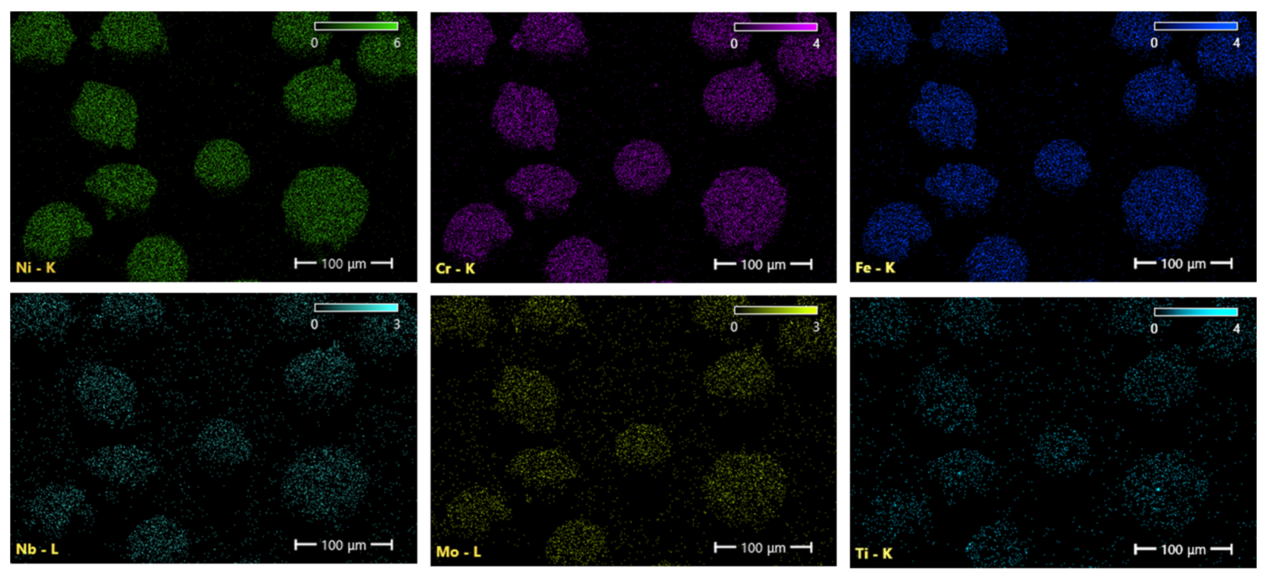
3.3. Powder Characterization

The morphology of the powder particles obtained by FESEM is shown in Figure 7a. Near-spherical large-size powder particles can be seen with a high number of small-size satellite powder particles on their surface. Agglomerated particles can also be observed. These effects are well-known features of gas-atomized powders. The smaller particles are lifted by gas circulating in the cooling chamber, and they collide and stick to larger particles that are still partly molten. The measured average circularity is quite high, 0.77. Figure 7b shows the wide particle size distribution of the deposited powder, which has a size range of 35–105 μm, where D50 is 71.3 μm. The EDX analysis shown in Figure 8 allowed us to determine that the main alloying elements (Ni, Cr, Fe, Mo, Nb, and Ti) were uniformly distributed in the powder particles without any significant segregation.

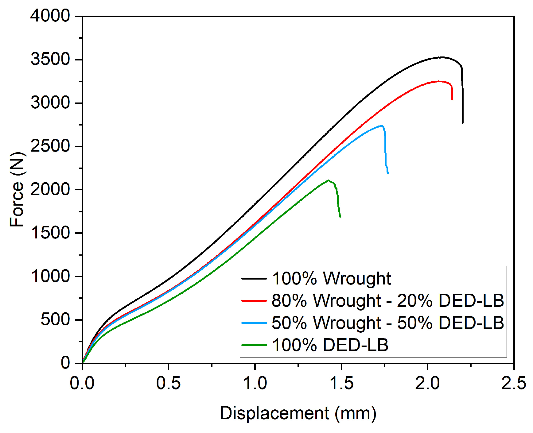
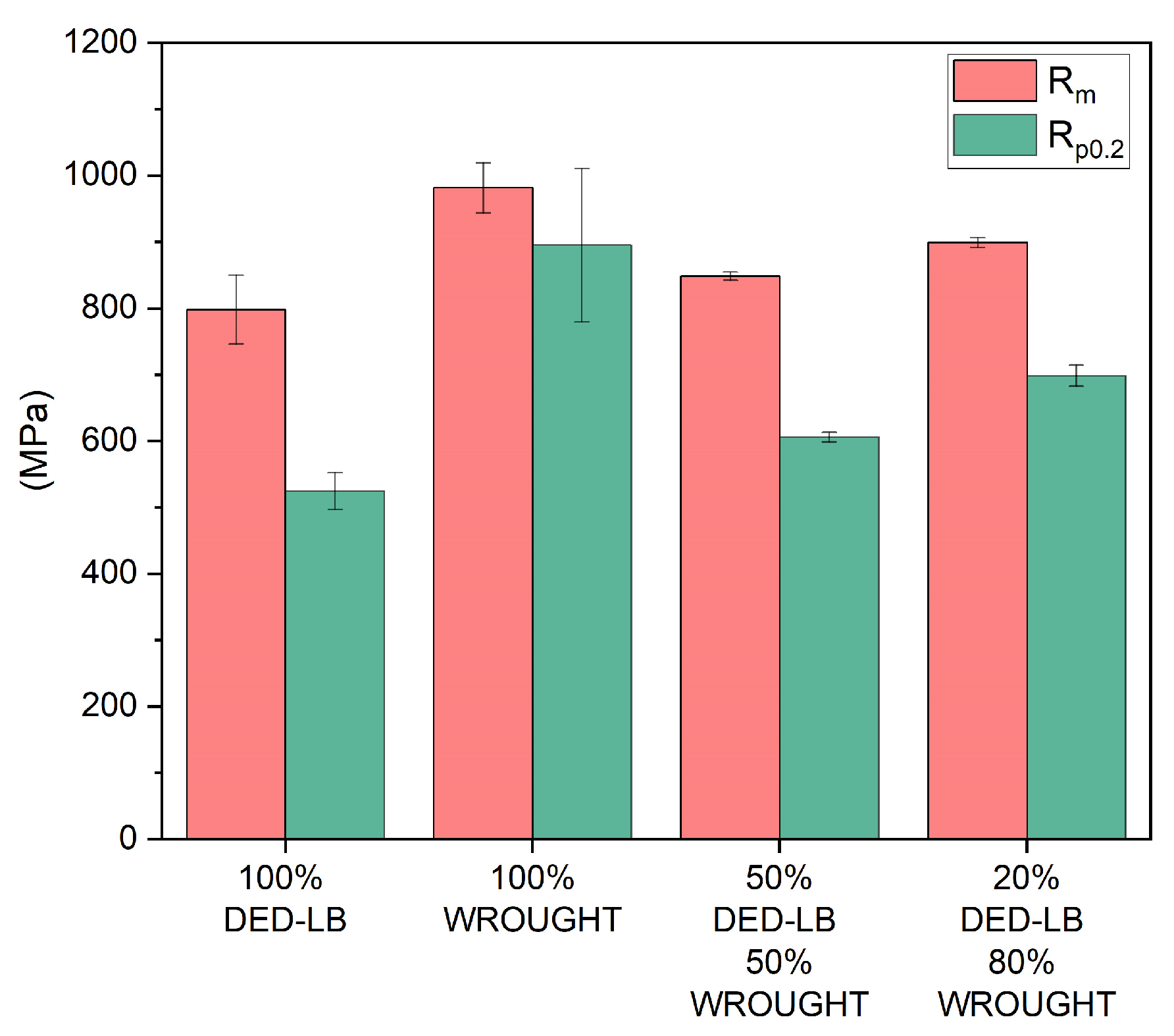
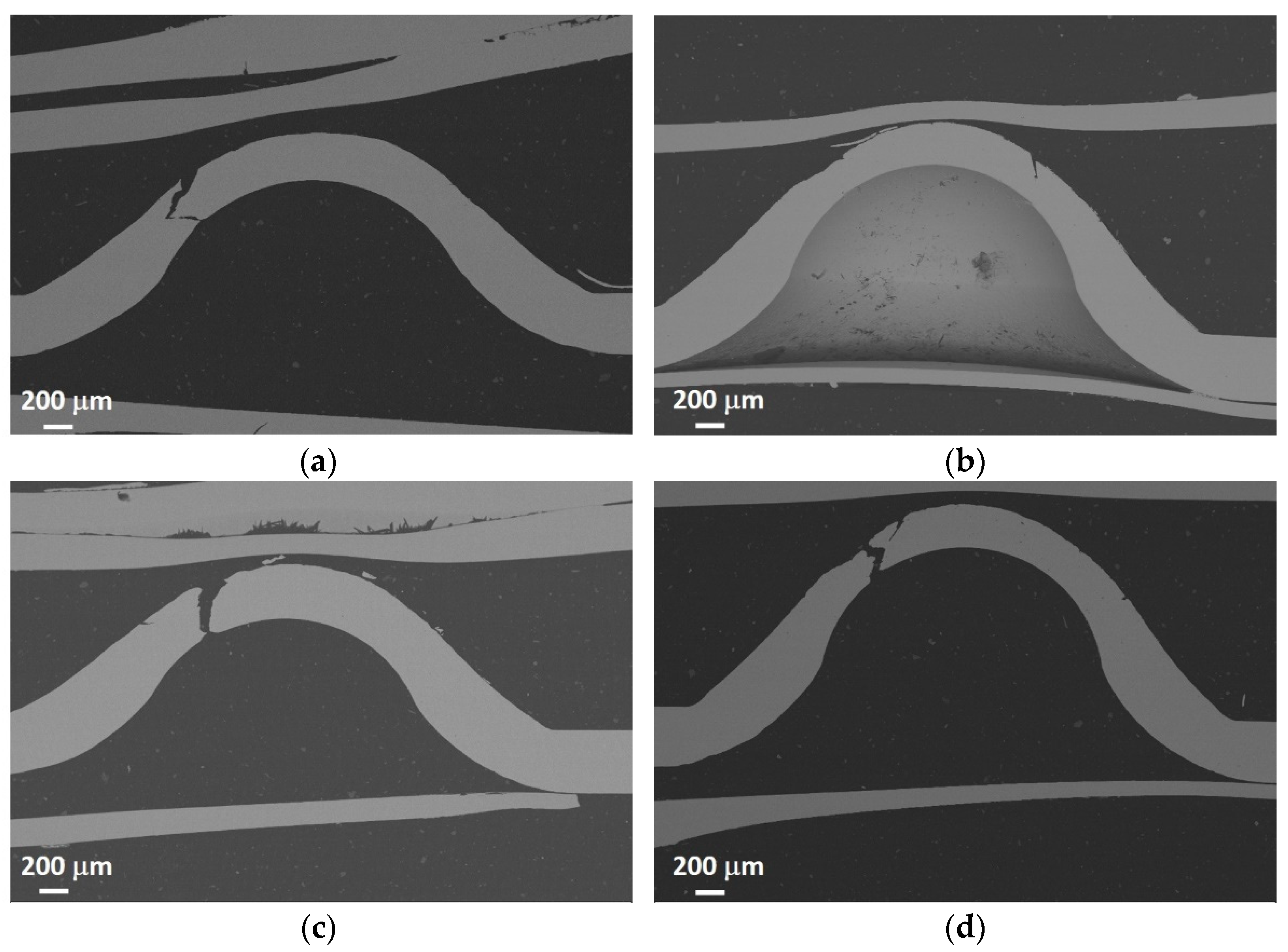
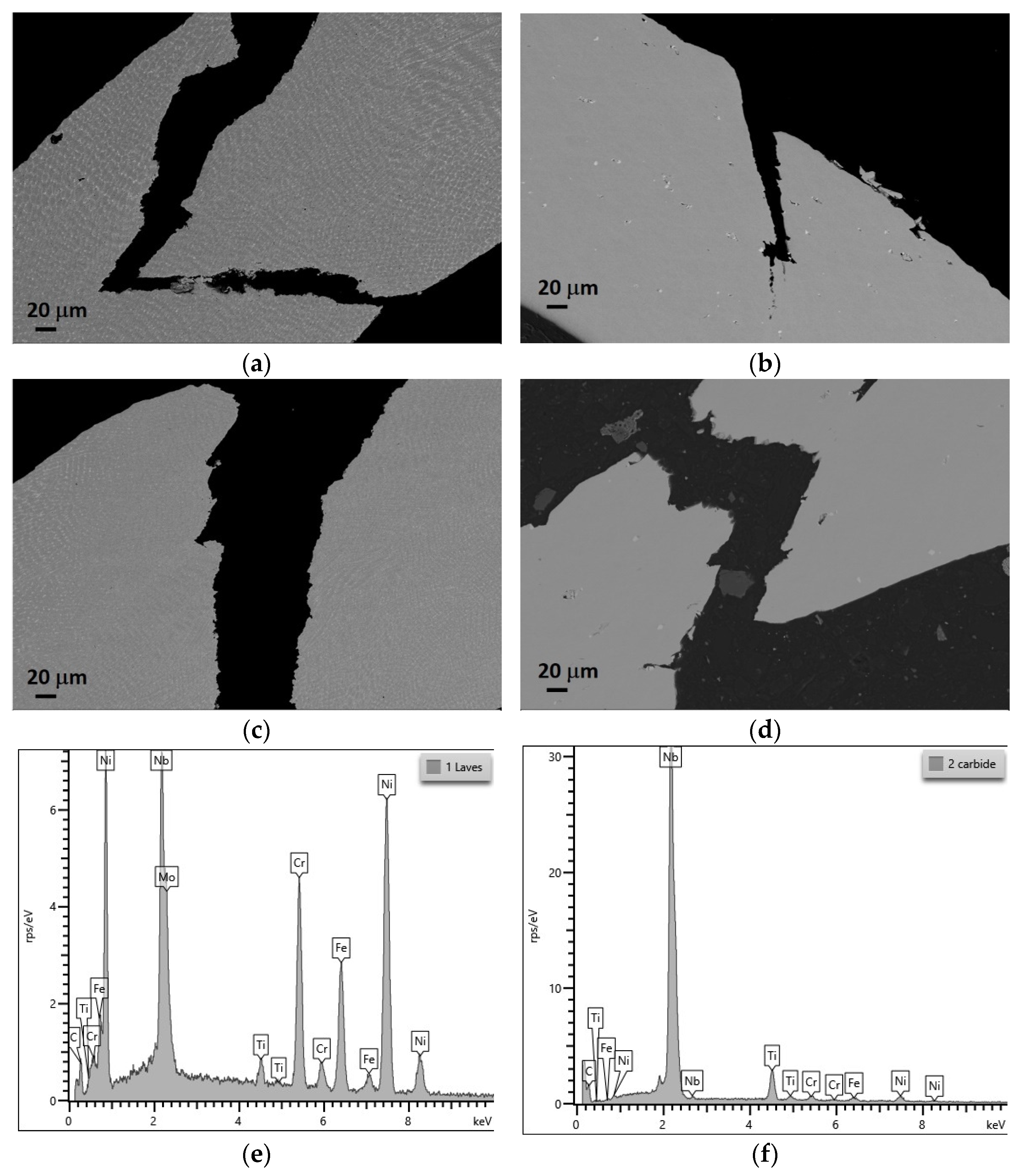
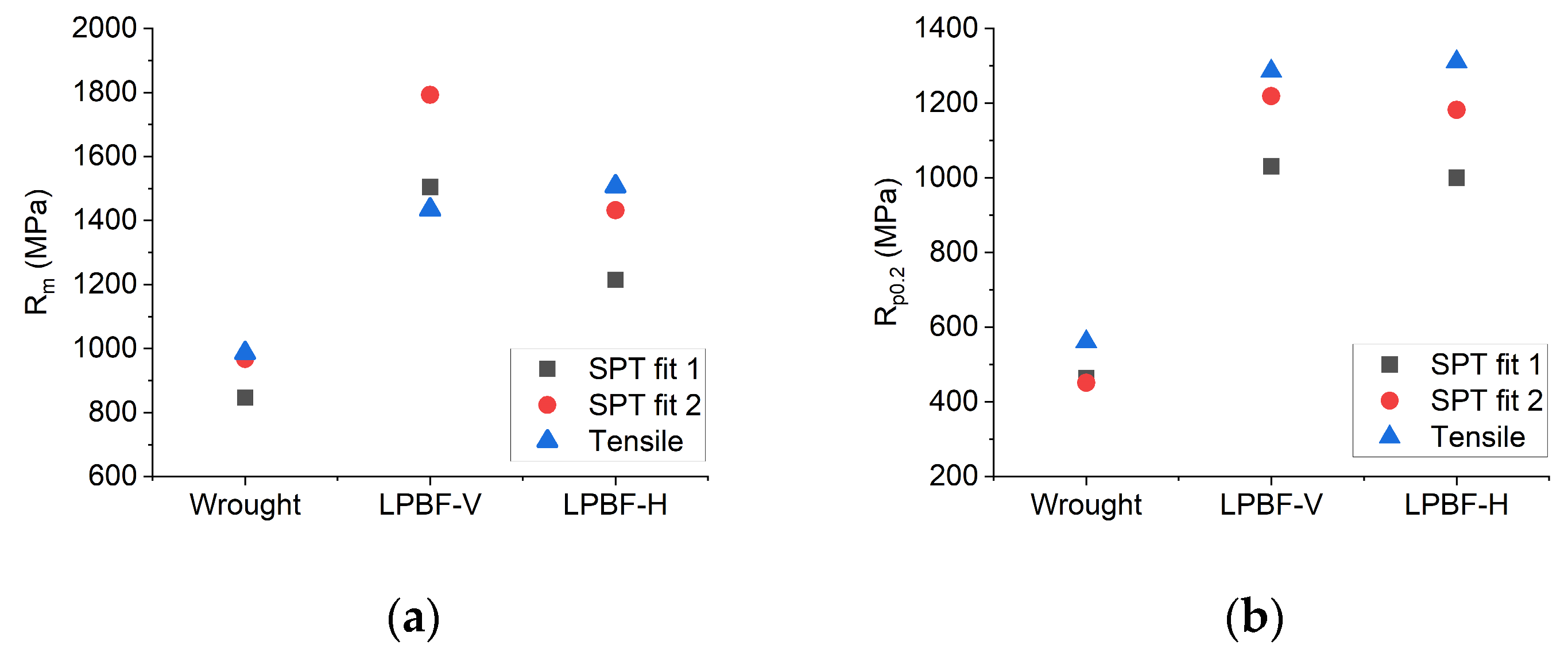
3.4. Mechanical Characterization of the Hybrid Coupons Based on the Small Punch Tests

Once all the specimens were tested and their force–displacement (Fv) curves obtained, the yield strength and maximum load for each condition were estimated according to the standard ASTM E3205 and using the empirical correlations described in Equations (2) and (3) for the yield strength and maximum load, respectively. A representative Fv curve for each condition is presented in Figure 9. As can be seen, there are clear differences in the curves for the different conditions. The 100% wrought sample yielded the highest load and displacement values while the 100% DED-LB sample yielded the lowest load and displacement values, with the curves of the joining section in between these extrema.
The parameters β R p 0.2   and β R m are constants that are defined by correlating tensile and SPTs on metallic materials. The values used in this report have been obtained from the literature [31], where βRm = 0.277 and βRp0.2 = 0.476. The results obtained are shown in Table 3, where the data correspond to average values of the three tested samples for each condition and the corresponding standard deviations. The results are plotted in Figure 10. Table 3 also shows for comparison the estimated values of the results obtained by weighting according to the corresponding percentage of the hybridized sample with the SPT experimental results for a pure DED-LB and pure wrought SPT samples. The fractures in the hybrid specimens were not equally distributed between the wrought and the DED-LB materials, but completely contained in the DED-LB side of the specimen for the 50/50 samples or along the weld line for the 20/80 specimens. Noteworthy, the results of the 50/50 estimations are within the standard deviation distance from the results of the 20/80 specimens. Summing up these two observations, the method proposed in this paper proves to be more suitable for assessing the bond line than the approaches in the works of García-Blanco [14], Kim [16], Serre [17], and Li [18].
Figure 11 and Figure 12 show the corresponding cross sections of the fractured SPT samples. In Figure 11, it can be observed that the crack affects all the wall thicknesses of the samples extracted from positions 1, 3, and 4 (see Figure 4a), while the sample of position 2 (100% base material) reaches about half of the wall thickness at the section analyzed. This sample also presents the best mechanical properties in the SPT test.
At a higher magnification (Figure 12), it can be observed that the fracture in position 3 (50% wrought + 50% DED-LB) occurred in the filler material, while in position 4 (80% wrought + 20% DED-LB), the fracture occurred in the joint area. The latter also revealed higher mechanical properties than the SPT sample centered in the joint area (50% wrought + 50% DED-LB). It is also interesting to note that the phases observed in the wrought material are NbC carbides (white phases in Figure 12d), while in the filler material, plenty of Laves phases are observed in the interdendritic areas (white phases in Figure 12a,c).
The best mechanical properties were obtained for the 100% wrought condition, while the lowest ones were obtained for the 100% DED-LB sample. It is well known that high mechanical properties can be achieved by additive manufacturing methods, but their mechanical properties are, in general, lower than those obtained for wrought products with a similar chemical composition, as is observed in the present work. The DED-LB technique is susceptible to generating defects such as oxides and pores in the deposited materials. These defects could compromise the performance of the final part, as also seen in the present work. The impact of this effect is amplified when additional layers are applied, since the higher the number of layers, the higher the risk of having defects.
The better performance of the wrought material could be also related to the absence of Laves phases in the wrought material. Laves phases are formed due to segregation during solidification and are known to impair the mechanical properties [32]. However, it has been reported that they can be eliminated mostly by adequate post-heat treatments [33]. Thus, an optimized post-heat treatment will probably enhance the mechanical properties of the DED-LB material.
It is worth noting that the results obtained in the SPTs that included the joining section (50% wrought + 50% DED-LB and ~80% wrought + 20% DED-LB) are both higher than the results for the pure DED-LB sample. Thus, the joining area is not the weak point. Therefore, it can be concluded that the Inconel 718 overlay processed via DED-LB on the wrought base adheres correctly.
The estimated values in Table 3, obtained by weighting the SPT experimental results, overestimate the experimental results by 40–45 MPa for Rm (~5%) and by 100–125 MPa for Rp0.2 (~17%). This means that the DED-LB contribution to the mechanical properties is slightly higher than expected by the mixed percentage of materials in the analyzed area.
Another interesting result is that there is a significant difference in the mechanical properties of Inconel 718 for the different conditions studied. Thus, the selected characterization method is sensitive enough to evaluate the mechanical properties of these types of hybrid components.
Lancaster et al. in [23] studied the efficacy of small-scale test methodologies to derivate the mechanical properties of additive manufactured materials. In the study, Inconel 718 produced by laser bed powder fusion (PBF-LB) was analyzed by means of a small punch test. The estimation of mechanical properties was carried out with a correlation where five materials were tested, including the Inconel 718. The estimation of the mechanical properties used in the presented study employs 16 materials among which Inconel is not included. Therefore, a comparison between both correlations is calculated using the results of the investigation of Lancaster et al.
Figure 13 shows the comparison between two SPT correlations and the tensile tests to assess whether the choice of fitting parameters from a reference without Inconel 718 is acceptable. “SPT fit 1” corresponds to the estimation of mechanical properties obtained by SPT in [23], “SPT fit 2” corresponds to the estimation of mechanical properties obtained by SPT in [23] but applying the correlation parameters βRm = 0.277 and β = 0.476, and “Tensile” corresponds to the tensile test performed in [23]. The notation of the original paper has been kept in the figure, LPBF-V and LPBF-H, where LPBF stands for PBF-LB, V stands for the vertical building direction, and H for the horizontal building direction.
It can be observed in Figure 13 that both correlations can be applied for the calculation of Rm but for Rp0.2, the “SPT fit 2” is a better estimation even though the correlation does not include the exact analyzed material, the Inconel 718. Thus, the fitting coefficients employed in this work are considered valid.
Furthermore, the results in [23] allow comparing DED-LB and PBF-LB for Inconel 718. The PBF-LB tests showed strength levels over 30% higher than DED-LB. This observation fits with the presence of Laves phases in the DED-LB micrographs.

4. Conclusions

The following conclusions can be drawn from the analyses carried out on the hybrid Inconel 718 coupon tested using SPT.
  • The SPT method is sensitive enough and useful to characterize mechanical properties at the different studied conditions: 100% wrought, 100% DED-LB, 50% wrought + 50% DED-LB, and 80% wrought + 20% DED-LB.
  • The best mechanical properties are obtained for the 100% wrought sample, while the lowest are for the 100% DED-LB sample.
  • The results obtained for samples that include a joining area between the wrought base and DED-LB-deposited material show that:
    The SPT values of the hybrid samples are below, but not far off, the weighted value of the SPT results of the pure samples: −4.5% for Rm and −17% for Rp0.2.
    Thus, the joining area is not the weak zone of the part, so it can be concluded that the overlay of Inconel 718 via DED-LB adhered correctly to the wrought Inconel 718 base.
  • The comparison between the different correlations for the estimation of the mechanical properties show that, even not including the exact material in the correlation, the results can be adequately estimated if the correlation considers materials with a wide range of mechanical properties.
  • The use of DED-LB for repairing Inconel 718 parts should be analyzed carefully if post-weld heat treatments are not applicable. The evolution of embrittling Laves phases is a source of decreases in the mechanical properties if the DED-LB is performed under conditions of high heat concentrations, as is the case of this work.
  • Regarding the extension of the proposed SPT methodology for the joint area assessment, the approach of this work is applicable for a DED-LB overlay thickness as thin as 1.5 mm while meeting standard testing method requirements. This is achieved by employing the reduced size specimen (Ø3 mm) from the EN 10371-2021 [34] SPT standard and accounting both for the 20/80 positioning and the machining clearance for specimen extraction. This opens a field of research on joints in thin DED-LB-manufactured parts that did not have an ad hoc technique available yet.

Author Contributions

Conceptualization: G.A.; methodology: G.A.; investigation: I.M. and J.I.A.; writing—original draft preparation: J.I.A. and A.I.F.-C.; writing—review and editing: I.M., J.I.A., A.I.F.-C., G.A. and C.A.; supervision: C.A.; project administration: A.I.F.-C.; and funding acquisition: G.A. All authors have read and agreed to the published version of the manuscript.

Funding

This research was partially funded by the ELKARTEK 2023 program from the Basque Government’s Department of Economic Development, Sustainability, and Environment, project ReIMAGIN under grant number KK-2023/00096. This work was also partially funded by the Basque Government under grant number 004-B2/2021, corresponding to the BIKAINTEK Program for PhD students. Finally, this work was also partially funded by the Department of Research and Universities of the Basque Government under grant number IT1542-22.

Data Availability Statement

Data available upon request to the authors.

Acknowledgments

The authors would like to thank Oier Barrenetxea for his contribution to the setup of the DED-LB process and Andrea Niklas for her contribution of cross-sections of fracture SPT samples’ analysis.

Conflicts of Interest

The authors declare no conflicts of interest.

References

  1. Malikov, A.G.; Golyshev, A.A.; Vitoshkin, I.E. Recent Trends In Laser Welding And Additive Technologies (Review). J. Appl. Mech. Tech. Phys. 2023, 64, 31–49. [Google Scholar] [CrossRef]
  2. Rodrigues, J.; Barter, S.; Das, R. The Role of Additive Manufacturing Towards Sustainable Aerospace Structures. In Proceedings of the Green Approaches in Sustainable Aviation, ISSASARES 2022, Sustainable Aviation, Melbourne, Australia, 25–27 November 2022. [Google Scholar] [CrossRef]
  3. Singh, G.; Mehta, A.; Vasudev, H. Sustainability of Additive Manufacturing: A Comprehensive Review. Prog. Addit. Manuf. 2024. [Google Scholar] [CrossRef]
  4. Sefene, E.M.; Hailu, Y.M.; Tsegaw, A.A. Metal Hybrid Additive Manufacturing: State-of-the-art. Prog. Addit. Manuf. 2022, 7, 737–749. [Google Scholar] [CrossRef]
  5. Srinivasan, D.; Ananth, K. Recent Advances in Alloy Development of Metal Additive Manufacturing in Gas Turbine/Aerospace Applications: A Review. J. Indian Inst. Sci. 2022, 102, 311–349. [Google Scholar] [CrossRef]
  6. Zhang, Y.; Lan, L.; Shi, Q. Microstructural evolution and precipitated phase characteristics in the fusion zone for the as-repaired Inconel 718 alloy by directed energy deposition additive manufacturing. Mater. Charact. 2023, 204, 113222. [Google Scholar] [CrossRef]
  7. Onuike, B.; Bandyopadhyay, A. Additive manufacturing in repair: Influence of processing parameters on properties of Inconel 718. Mater. Lett. 2019, 252, 256–259. [Google Scholar] [CrossRef]
  8. Ramiro, P.; Galarraga, H.; Pérez-Checa, A.; Ortiz, M.; Alberdi, A.; Bhujangrao, T.; Morales, E.; Ukar, E. Effect of Heat Treatment on the Microstructure and Hardness of Ni-Based Alloy 718 in a Variable Thickness Geometry Deposited by Powder Fed Directed Energy Deposition. Metals 2022, 12, 952. [Google Scholar] [CrossRef]
  9. Kang, M.; Jiang, M.; Sridar, S.; Xiong, W.; Xie, Z.; Wang, J. Effect of Multiple Repair Welding on Crack Susceptibility and Mechanical Properties of Inconel 718 Alloy Casting. J. Mater. Eng. Perform. 2022, 31, 254–261. [Google Scholar] [CrossRef]
  10. Fisk, M.; Lundbäck, A. Simulation and validation of repair welding and heat treatment of an alloy 718 plate. Finite Elem. Anal. Des. 2012, 58, 66–73. [Google Scholar] [CrossRef]
  11. Wu, J.; Xu, M.; Lin, S.; Zhang, Q.; Wu, X.; Tian, J.; Wang, Z. Refining microstructures and enhancing mechanical properties of Inconel 718 weldment via fast-frequency double pulsed waveforms adopting in FFP-TIG. J. Mater. Process. Technol. 2023, 314, 117882. [Google Scholar] [CrossRef]
  12. Ma, J.; Zhang, Y.; Li, J.; Cui, D.; Wang, Z.; Wang, J. Microstructure and mechanical properties of forging-additive hybrid manufactured Ti–6Al–4V alloys. Mater. Sci. Eng. A 2021, 811, 140984. [Google Scholar] [CrossRef]
  13. Zu, Y.; Cao, Y.; Zhen, Y.; Li, F.; Wu, G. Determination on the fracture toughness of the welded joints of X80 pipeline steels based on small punch test. Eng. Fract. Mech. 2023, 291, 109525. [Google Scholar] [CrossRef]
  14. García-Blanco, I.; García, T.E.; Cabezas, J.G.; González, R.; Álvarez, G.; Rodríguez, C. Use of the small punch test for mechanical characterization of co– based laser cladding joint. Eng. Fail. Anal. 2024, 159, 108129. [Google Scholar] [CrossRef]
  15. Taheri, M. Development of a novel method for measuring the interfacial creep strength of laser cladding coatings. Results Opt. 2022, 7, 100226. [Google Scholar] [CrossRef]
  16. Kim, B.J.; Sim, Y.B.; Lee, J.H.; Kim, M.K.; Lim, B.S. Application of small punch creep test for Inconel 617 alloy weldment. Procedia Eng. 2011, 10, 2579–2584. [Google Scholar] [CrossRef]
  17. Serre, I.; Vogt, J.-B. Mechanical properties of a 316L/T91 weld joint tested in lead–bismuth liquid. Mater. Des. 2009, 30, 3776–3783. [Google Scholar] [CrossRef]
  18. Li, J.-F.; Kawai, M.; Kikuchi, K.; Igarashi, T.; Kurishita, H.; Watanabe, T.; Kawasaki, A. Strength proof evaluation of diffusion-jointed W/Ta interfaces by small punch test. J. Nucl. Mater. 2003, 321, 129–134. [Google Scholar] [CrossRef]
  19. Courtright, Z.S.; Leclerc, N.P.; Kim, H.N.; Kalidindi, S.R. Critical Comparison of Spherical Microindentation, Small Punch Test, and Uniaxial Tensile Testing for Selective Laser Melted Inconel 718. Appl. Sci. 2021, 11, 1061. [Google Scholar] [CrossRef]
  20. Lu, F.-Y.; Wan, H.-Y.; Ren, X.; Huang, L.M.; Liu, H.L.; Yi, X. Mechanical and microstructural characterization of additive manufactured Inconel 718 alloy by selective laser melting and laser metal deposition. J. Iron Steel Res. Int. 2022, 29, 1322–1333. [Google Scholar] [CrossRef]
  21. Arrizubieta, J.I.; Klocke, F.; Klingbeil, N.; Arntz, K.; Lamikiz, A.; Martinez, S. Evaluation of efficiency and mechanical properties of Inconel 718 components built by wire and powder laser material deposition. Rapid Prototyp. J. 2017, 23, 965–972. [Google Scholar] [CrossRef]
  22. Trosch, T.; Strößner, J.; Völkl, R.; Glatzel, U. Microstructure and mechanical properties of selective laser melted Inconel 718 compared to forging and casting. Mater. Lett. 2016, 164, 428–431. [Google Scholar] [CrossRef]
  23. Lancaster, R.J.; Barnard, N.C.; Haigh, B.; Sackett, E.E.; May, P.E.; Douglas, R.J.; Britton, D.; Jeffs, S.P. Evaluating the efficacy of alternative small scale test methodologies in deriving the mechanical properties of additive manufactured materials. J. Mater. Res. Technol. 2023, 26, 9328–9345. [Google Scholar] [CrossRef]
  24. Wang, L.Y.; Zhou, Z.J.; Li, C.P.; Chen, G.F.; Zhang, G.P. Comparative investigation of small punch creep resistance of Inconel 718 fabricated by selective laser melting. Mater. Sci. Eng. A 2019, 745, 31–38. [Google Scholar] [CrossRef]
  25. Peng, J.; Gao, M.; Zhang, H.; Geng, X.; Liu, X.; Pan, H. Small punch creep test reveals the differences of high-temperature creep behaviours for laser powder bed fusion and Rolled Inconel 718 alloys. Mater. Sci. Eng. A 2023, 886, 145698. [Google Scholar] [CrossRef]
  26. ASTM E1086; Standard Test Method for Analysis of Austenitic Stainless Steel by Spark Atomic Emission Spectrometry. ASTM International: West Conshohocken, PA, USA, 2022.
  27. UNE-EN 10361; Aceros aleados. Determinación del Contenido de Níquel. Método por Espectrometría de Emisión óptica con Fuente de Plasma Inducido. AENOR: Madrid, Spain, 2016.
  28. ASTM E1019; Standard Test Methods for Determination of Carbon, Sulfur, Nitrogen, and Oxygen in Steel, Iron, Nickel, and Cobalt Alloys by Various Combustion and Inert Gas Fusion Techniques. ASTM International: West Conshohocken, PA, USA, 2018.
  29. ASTM E3205; Standard Test Method for Small Punch Testing of Metallic Materials. ASTM International: West Conshohocken, PA, USA, 2020.
  30. Miguel, I.; Berriozabalgoitia, I.; Artola, G.; Macareno, L.M.; Angulo, C. Small Punch Test on Jominy Bars for High-Throughput Characterization of Quenched and Tempered Steel. Metals 2023, 13, 1797. [Google Scholar] [CrossRef]
  31. García, T.E.; Rodríguez, C.; Belzunce, F.J.; Suárez, C. Estimation of the mechanical properties of metallic materials by means of the small punch test. J. Alloys Compd. 2014, 582, 708–717. [Google Scholar] [CrossRef]
  32. Donachie, M.J.; Donachie, S.J. Superalloys: A Technical Guide, 2nd ed.; ASM International: Materials Park, OH, USA, 2002. [Google Scholar] [CrossRef]
  33. Yu, X.; Lin, X.; Liu, F.; Wang, L.; Tang, Y.; Li, J.; Zhang, S.; Huang, W. Influence of post-heat-treatment on the microstructure and fracture toughness properties of Inconel 718 fabricated with laser directed energy deposition additive manufacturing. Mater. Sci. Eng. A 2020, 798, 140092. [Google Scholar] [CrossRef]
  34. EN 10371; Metallic Materials—Small Punch Test Method. CEN: Brussels, Belgium, 2021.
Figure 1. Experimental setup for the coupon manufacturing.
Applsci 14 06420 g001
Figure 2. Real vs. nominal laser power.
Applsci 14 06420 g002
Figure 3. (a) Single clad tests and (b) overlap tests to define the optimal process parameters.
Applsci 14 06420 g003
Figure 4. (a) Scheme of the DED-LB deposition strategy for the wrought base material. Cuts made for the metallographic analysis and for the SPT sample extraction are indicated (all indicated dimensions are in millimetres). (b) Details of the positions of the extracted cylinders for the SPTs, where (1) is 100% filler material, (2) is 100% wrought base material, (3) is 50% filler and 50% base material, and (4) is 20% filler and 80% base material. (c) Filler–base joint position in the SPT for situations (3) and (4).
Applsci 14 06420 g004
Figure 5. Custom-designed SPT tool.
Applsci 14 06420 g005
Figure 6. (a) Cross-section of test specimen 6 and (b) cross-section of the deposited coupon.
Applsci 14 06420 g006
Figure 7. (a) Morphology of the Inconel 718 powder. Satellite and agglomerated particles are clearly observed. (b) Particle size distribution of the Inconel 718 powder.
Applsci 14 06420 g007
Figure 8. EDX mapping analysis of the Inconel 718 powder particles shown in Figure 7a.
Applsci 14 06420 g008
Figure 9. SPT Fv characteristic curve for each condition.
Applsci 14 06420 g009
Figure 10. Estimation of the yield strength and tensile strength from the SPTs for the hybrid Inconel 718 tests coupons compared with pure DED-LB and pure wrought samples.
Applsci 14 06420 g010
Figure 11. Cross-sections of fractured SPT samples extracted from positions indicated in Figure 4a. (a) Pos. 1: 100% filler material, (b) Pos. 2: 100% wrought base material, (c) Pos. 3: 50% filler and 50% base material, and (d) Pos. 4: 20% filler and 80% base material.
Applsci 14 06420 g011
Figure 12. Cross-sections of fractured SPT samples extracted from positions indicated in Figure 4a. (a) Pos. 1: Fracture in the filler material, (b) Pos. 2: Fracture in the wrought base material, (c) Pos. 3: Fracture occurs in the filler material, and (d) Pos. 4: Fracture occurs in the base material, (e) in the filler material (Pos. 1) Laves phases are observed in the interdendritic spaces and (f) while the base material shows the presence of small NbC carbides (Pos. 2).
Applsci 14 06420 g012
Figure 13. Comparison between different correlations in SPT for the characterization of Inconel 718. (a) Maximum load, Rm. (b) Yield strength, Rp0.2.
Applsci 14 06420 g013
Table 1. DED-LB process parameter optimization tests, where the laser power (P), machine feed rate (F), and powder mass rate (Q) were varied.
Test NumberP [W]F [mm/min]Q [g/min]
15005005.5
25505005.5
36005005.5
45005255.5
55505255.5
66005255.5
75005505.5
85505505.5
96005505.5
105005006.0
115505006.0
126005006.0
135005256.0
145505256.0
156005256.0
165005506.0
175505506.0
186005506.0
Table 2. Chemical compositions in wt. % of the employed wrought base material, filler Inconel 718 powder, and optimum deposited overlay.
TypeNameNiCrMoFeNbTiMnCSiAlOthers
Wrought baseInconel 718Bal.18.12.7918.45.070.950.0670.0430.0560.60<0.4
PowderInconel 718Bal.18.92.9118.04.830.860.0740.0390.0340.49<0.2
DED-LB depositedInconel 718Bal.18.52.9017.44.930.780.0740.0470.0420.49<0.2
Table 3. SPT results obtained for Inconel 718 for the conditions studied: average value and standard deviation measured by SPT and an estimation of the results, taking into account the percentage of hybridized technology and the experimental results for pure DED-LB and pure wrought samples.
ReferenceRm (MPa)Rp0.2 (MPa)
AverageDeviationAverageDeviation
100% DED-LBMeasured by SPT7985252428
100% WROUGHTMeasured by SPT98138895116
50% DED-LB +
50% WROUGHT
Measured by SPT84866067
Weighed estimation (50/50)890-710-
20% DED-LB +
80% WROUGHT
Measured by SPT899769816
Weighed estimation (20/80)944-821-
Disclaimer/Publisher’s Note: The statements, opinions and data contained in all publications are solely those of the individual author(s) and contributor(s) and not of MDPI and/or the editor(s). MDPI and/or the editor(s) disclaim responsibility for any injury to people or property resulting from any ideas, methods, instructions or products referred to in the content.

