Abstract
Optimization of the energy consumption of a Dorna 1 commercial robot was carried out by replacing the original materials of the links (aluminum) with a lighter and more resistant material (carbon fiber) with the aim of lowering the operating costs of the robot. For this reason, a reduction in the total mass of the robot of 11.08% was achieved by replacing the original materials. In addition, simulations were carried out using finite element analysis to verify that the mechanical resistance of the optimized parts was adequate according to the level of demand that occurs during the operation of the robot. Subsequently, a comparison of the energy consumption of the original robot and the robot with the optimized parts was carried out using the Internet-of-Things device. The tests were carried out at three different speeds—1000, 3000, and 9000 deg/min—for 15 min by executing a pre-established routine starting from home. The results showed that at all test speeds, there were energy savings, but the greatest energy savings occurred at the speed of 3000 degrees/min in the range of 3.66%. With this result, it has been shown that the integration of light materials in robots can achieve energy savings.
1. Introduction
The importance of robotics in modern times is crucial, as robots nowadays have a variety of industrial applications, such as automotive, casting, and petrochemicals, since they can perform activities continuously and accurately for long periods of time. The robotic arm is one of the industrial robots with the widest range of applications, because its design is similar to that of the human arm, but with its abilities exponentially enhanced. Likewise, they reduce the risks associated with labor [1]. They can also be very useful in planning tasks in an industrial environment for decision making in the planning stage of cell design [2]. Industrial robots consume large amounts of energy during their long operational life. These large amounts of energy consumption result from two main forces: one is joint friction, and the second is the force of gravity acting on the robot’s axes, tools, and payloads [3]. These factors result in additional energy consumption by motor controllers. When multifunction robots work in cells in automated manufacturing systems, it is also desirable to perform energy optimizations to improve productivity [4]. For this reason, increasing their energy efficiency is of great importance.
Years ago, energy efficiency in robots was not seen as a basic requirement in the design of these devices; rather, developments focused more on improving robot performance such as precision and productivity [5]. However, this landscape has recently changed due to the global aspiration to reduce energy consumption and hence the carbon footprint generated by various industries [6,7]. In addition to this environmental issue, as the prices of energy sources increase, the problem of using other sources (the so-called alternative or renewable sources) to power various machines and mobile units becomes more acute [8]. The topic of energy efficiency in robotics is an area that requires further development, as there are still few published articles on the subject [9,10].
Some possible approaches to solve the energy-efficiency problem include restricting parameters such as speed and acceleration, or adjusting the design of the manipulator, for example its length, diameters, volume, density, and weight [11]. Meanwhile, other authors have focused their research on energy reduction by optimizing design and implementing eco-efficient planning [12]. Energy reduction is primarily achieved through lightweight design, introducing new energy-saving hardware, or adjusting the production line [13,14,15,16,17]. For their part, Riazi et al. [18] have chosen to optimize the algorithm of a multi-robot industrial system and reported achieving energy savings above 45%. However, hardware adjustments require a considerable investment, which limits their practical application [19]. Pupaza et al. [20] made geometric changes to the second link to reduce the material usage and performed a strength analysis (this link is the furthest away). They found that the robot became lighter and no additional deformations occurred under the same load.
During the design of robots it is very important to know the reach of the extended arm, since it is the most critical condition in addition to the maximum payload, these conditions will result in the selection of more powerful motors and selection of more rigid materials [21]. In a similar study, Supriya Sahu et al. [22] they performed FEM analyzes to simulate the loads of a 6-axis robotic arm and calculated the deformation values. They identified the location of the maximum deformation values and attempted to stabilize the robot by implementing appropriate minimization techniques in the parts where the deformation is maximum.
On the other hand, Zhou et al. [23] focused their optimization study by changing the design to identify the range of loads that a robot can safely lift to increase its load-lifting capacity. Yao et al. [24] carried out a validated design with finite element and topological optimization, and analyzed the upper arm of a welding robot in the most unfavorable working conditions, both in static and dynamic conditions; they showed a weight decrease of 17.9%. Yin et al. [25] presented a study on a general structure optimization design approach to reduce the mass of the robotic arm; this method was implemented by simulating a parameterized robotic arm to obtain an optimal design of the robotic arm. Haibin Yin et al. [26] presented an optimization study of a robot to reduce weight, combining carbon fiber (CF) and aluminum (Al) material, performed a simulation for structural analysis, and finally an experimental prototype was built to validate the proposed method and compare it with the real aluminum model.
However, although there were some previous works that contributed to the structural optimization of industrial robots for energy saving, most of the works were at the level of numerical analysis and simulation optimization [27,28,29]. Very few of them have considered real manufacturing and assembly processes of lighter structural components with high mechanical properties, such as carbon fiber [30]. Furthermore, because the optimizations were not implemented and experiments were not carried out in a real way, they could not accurately validate the real performance parameters, which entails extra work on the part of the authors to be able to complement the cycle. The authors who carried out the experimental validation carried out their tests under static conditions but without considering composite materials, only the topological optimization of the original parts while preserving the original materials.
Therefore, our team combined the manufacturing of composite materials and their implementation in the replacement of the original parts of the robot with new materials. Once the materials were replaced, experimental tests were carried out in dynamic robot conditions taking into account the maximum demand of the robot. In the end, it was shown that this application of materials can greatly help the energy reduction of robots.
The paper is organized into several sections that delineate the study of the energy efficiency between the Dorna 1 commercial robotic arm with joints made of aluminum versus the Dorna robotic arm with joints made of carbon fiber by CIDESI. Section 2 describes the materials and methods used to study energy efficiency. In Section 3, we discuss our results. In Section 4, we present the conclusion. Finally, we list the references supporting this work.
2. Materials and Methods
The following materials (see Table 1) are used for the process described in Figure 1. This process consists of six stages, which are: chemical properties report; structural optimization using finite element analysis (FEA) simulation; manufacturing; assembly; comparative report; and energy efficiency. These stages are fundamental for the development and evaluation of energy efficiency between two robotic arms.

Figure 1.
General proposal for the study of energy efficiency between two robotic arms.
Figure 1.
General proposal for the study of energy efficiency between two robotic arms.


Table 1.
Description of the materials used.
Table 1.
Description of the materials used.
| Name | Description |
|---|---|
| SolidWorks [31] | SolidWorks premium version 2023, a 3D CAD design software application for modeling parts and assemblies in 3D. It was used for the mechanical design of the structural joints of the robot arm. |
| Dorna Robotics [32] | Dorna Robotics creates robots and software that are efficient, accurate, and affordable for industrial automation, and use in industrial or research applications. The Dorna Robotics API and a Dorna v1 5-axis robotic arm were used. |
| IoT energy [33] | The Internet of Things (IoT) describes devices with sensors, processing capabilities, analytics, and communication protocols that enable data exchange with other software and hardware systems. This device was required to detect the energy consumption of robotic arms in different load conditions. |
| Jetson Nano [34] | The Jetson Nano module is a small AI computer that has the performance and power efficiency to take on modern AI workloads and execute multiple tasks. The electronic board allowed the control of the movements of the robot arm. |
| Python [35] | Python is a high-level, general-purpose programming language. Version 3.12.3 was used for the control logic of the robot arm. |
| AWS [36] | Cloud computing platform offered by Amazon, with a wide range of services (DynamoDB, S3, Lambda, IAM, API Gateway). It allowed the development and deployment of the application in the cloud quickly and scalably. |
| Abaqus CAE [37] | Complete solution for Abaqus finite element modeling, visualization, and process automation, research standard version 2018. The properties of carbon fiber (plane wave biaxial 3k) and epoxy resin (Epolam 2015) are loaded into the Abaqus software to calculate the structural strength. |
2.1. Chemical Properties
To ascertain the material used in the robotic arm plate, it was necessary to carry out a theoretical characterization of the material based on the results of the chemical characterization requested from the chemical analysis laboratory of CIDESI. The chemical characterization was carried out on one of the six plates of the robotic arm, this being a representative sample of all the plates. The results of the chemical characterization showed that the robotic arm material consists of an aluminum–magnesium alloy with a minimum percentage of iron and chromium. The chemical composition of the material matches the nominal chemical composition of an AA5052 alloy according to the Aluminum Association designation system defined by ANSI H35.1 for mechanically worked aluminum alloys. AA 5052 alloy belongs to the 5XXX family of alloys. The main alloying element in these alloys is magnesium in the range of 0.5 to 6.0 wt% Mg. Aluminum 5052 contains magnesium as the primary alloying element. It is a non-heat-hardenable alloy offering good formability and weldability, medium fatigue strength, and very good corrosion resistance, particularly in seawater, and is commonly used in sheet, plate, and tube form. AA5052 alloy is also known as ASTM B209 [38] and AMS 4015 [39] in plate and sheet. The physical and mechanical properties of AA5052 aluminum are presented in Table 2.
Table 2.
Physical and mechanical properties of AA5052 aluminum.
2.2. Structural Optimization
The structural optimization of the commercial robot Dorna 1 was carried out by replacing the original aluminum AA5052 material of the robot with woven carbon fiber (plane wave biaxial 3k) and epoxy resin (Epolam 2015). The objective of the optimization was to preserve the structural resistance and thickness of the parts but reduce the weight to increase the energy efficiency of the robot. SolidWorks software was used to draw the structural elements of the robot and later Abaqus software was used for calculations using FEA simulation. Figure 2 shows the solid 3D model of the original configuration of the robot.
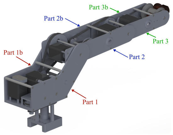
Figure 2.
Original robot assembly.
2.3. Robot Arm Manufacturing
The laminates were manufactured using a 1 × 1 plain weave 3K carbon fiber supplied by Quintum. The carbon fabric weighs 198 g/m2, with a tensile strength of 2138 MPa and an elastic modulus of 227 GPa. The carbon fiber is impregnated with Epolam 2015 epoxy resin from Sika. According to the technical sheet, the epoxy resin has a viscosity of 1.55 mPa.s and a density of 1.15 g/cc. The Epolam 2015 hardener, with amino groups, was used as a catalyst in a mixing ratio of 32 by weight and a working time of approximately 140 min at room temperature. The carbon-fiber-reinforced polymer (CFRP) laminates were prepared using the vacuum-assisted resin infusion (VARI) method in a controlled environment. The vacuum pressure was −20 inHg and the resin cured in approximately 24 h (∼25 °C). The orientation of the carbon fiber fabrics was almost isotropic, with a stacking sequence of [0/90]6s. The CFRP laminates had 16 layers of carbon fiber (CF) plain weave and nominal dimensions of 600 mm × 500 mm × 3 mm (see Figure 3). The entire laminate was covered with a vacuum bag sealed with butyl tape.
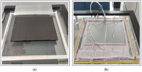
Figure 3.
Manufacturing process of CFRP laminates. (a) Stacking of carbon fiber plies. (b) Laminated CFRP plate in VARI process.
More information on composite manufacturing can be found in a previous research article [40]. The robot arm parts were cut on a waterjet cutting machine. At the end of manufacturing, the physical and mechanical properties of the carbon fiber composite were obtained and are presented in the Table 3.
Table 3.
Physical and mechanical properties of the carbon fiber/epoxy resin composite.
2.4. Robot Arm Assembly
In order to assemble this carbon fiber (CF) robot arm, all parts and joints must be joined according to the predetermined design. Each stepper motor must be mounted on its respective joint, ensuring precise alignment to allow the desired movement. The motor controllers are then connected to a control board. It is essential to connect the power and signal cables correctly, checking polarity and correct pin assignment. Finally, the control system is tested to coordinate the movement of the motors and tests are performed to calibrate and ensure smooth and accurate operation of the CF robotic arm.
2.5. Comparative
For the analysis of energy consumption, the performances of the aluminum robot arm and the carbon fiber robot arm were evaluated under the same movement scheme from their position in “Home” during a time span of t minutes with n different speeds (deg/min), (deg/min), and (deg/min) (see Table 4).
Table 4.
Arbitrarily suggested data for energy efficiency tests.
2.6. Energy Efficiency
To calculate the energy efficiency of this robot arm (see Equation (1)), the useful power it produces () in Watts (W), and the total power it consumes () in Watts (W) will be measured through an IoT device. The useful power is the effective energy used to perform the desired work, while the total power is the energy supplied to the robot arm. Subsequently, the useful power is divided by the total power and the result is multiplied by 100 to obtain a percentage. The formula is:
where:
- () is energy efficiency,
- () is useful energy,
- and () is total energy consumed.
3. Results and Discussion
3.1. Finite Element Analysis of Original Parts
The numerical simulation to ascertain the resistance values of the parts was carried out only on Part 1 and Part 1b (see Table 5), which are the parts that support most of the weight of the robot components. To do this, a part was modeled with continuous shell-type elements, taking as initial conditions a force of 20 N applied at the point, as shown in Table 5 for all structural elements. Conditions of restrictions (fixed) of the elements in the X, Y, and Z axes were also applied for both displacement and rotation; this can be seen in Table 5.
Table 5.
Initial conditions and results of finite element analyses.
Firstly, the resistances of the original parts (aluminum) were obtained using the mechanical properties of Table 2, and subsequently the mechanical resistances of the optimized parts were obtained using the mechanical properties of the carbon fiber shown in Table 3.
Sixteen layers of 0.25 mm-thick carbon fiber are modelled in order to obtain the final thickness of 4 mm, and the stacking of the layers is shown in Figure 4. According to the results obtained from the simulation, there is a Von Mises stress of 2.32 MPa, well below the yield stress (90 MPa) of Part 1 (aluminum). According to the results obtained from the simulation, there is a Von Mises Stress of 3.26 MPa, well below the yield stress (90 MPa) for Part 1b (aluminum).
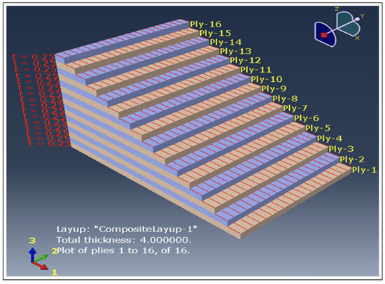
Figure 4.
Carbon fiber layer stacking.
From the results of the simulations of the carbon fiber part, it was calculated that the part is subjected to a stress of 2.53 MPa, which is well below the resistances obtained experimentally (see Table 3). These results are obtained for Part 1 made from carbon fiber. In the case of Part 1b, made of carbon fiber, the results show that the part is subjected to a stress of 3.68 MPa, which is well below the resistances obtained experimentally (see Table 3).
3.2. Mass Optimization
The total mass of the original aluminum parts was 721.95 g, while the mass of the carbon fiber/resin components was approximately 401.19 g, which results in a decrease of with respect to the original mass of the parts. If the parts are optimized, the mass is reduced to 326.51 g, a reduction compared to the aluminum parts. These masses were calculated using SolidWorks software, taking into account the properties in Table 2 and Table 3. The results of the optimization of the mass of the parts are shown in Table 6.
Table 6.
Mass of the original parts.
3.3. Finite Element Analysis of Optimized Parts
Subsequently, an optimization process was carried out. This process consisted of eliminating only certain areas of the parts where the structural integrity of the part was not compromised, with the purpose of reducing the weight of the parts (see Table 7). The numerical simulation of the parts with the optimized mass was carried out with the same initial conditions as in Table 5. According to the results, the part is subjected to a stress of 4.64 MPa, which is well below the resistances obtained experimentally (see Table 3). According to the results, the part is subjected to a stress of 2.93 MPa, which is well below the resistances obtained experimentally (see Table 2).
Table 7.
Results of the finite element analysis on the optimized parts.
3.4. Cutting Carbon Fiber Parts
After completing the optimization of the masses of the robot parts and after manufacturing the carbon fiber plates, the parts were cut using a waterjet cutting machine. The pieces obtained can be seen in Figure 5. Six optimized carbon fiber pieces were obtained.
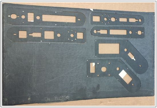
Figure 5.
Optimized parts cut from a plate of carbon fiber material.
3.5. Robot Assembly with Optimized Carbon Fiber Parts
Once the cut parts were obtained, the joints of the robot arm were assembled using the six side parts for each link in carbon fiber material. Each of the components that make up the Dorna robot arm were placed as shown in Figure 6.
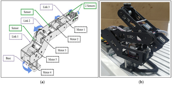
Figure 6.
(a) Robotic arm with its elements. (b) Robotic arm with carbon fiber parts.
3.6. Optimized Robot Weighing
Once the aluminum and carbon fiber robotic arms were assembled, they were weighed to determine the difference in weight between both robots. The weight of the Aluminum robot is 4610.12 g (see Figure 7a); while the carbon fiber arm has a weight of 4099.42 g (see Figure 7b). The latter is lighter than the original by 11.08%.
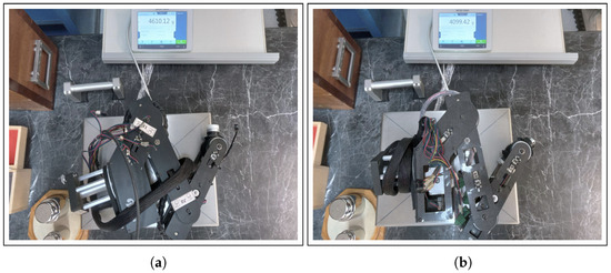
Figure 7.
Weighing of Dorna 1 Robotic Arms. (a) Aluminum robotic arm. (b) Carbon fiber robotic arm.
3.7. Energy Efficiency
For the study of energy efficiency between the original Dorna 1 aluminum robotic arm and the object of study (the carbon fiber robotic arm optimized at CIDESI), an IoT device was developed (see Figure 8b) to detect the consumption energy of both robotic arms. The device has an ESP32 chip and was programmed in C language for data collection. The device was connected to the driver of the robotic arm to detect energy consumption during the operation of this arm. This driver was used to control both arms and be able to measure efficiency in the same frame of reference.
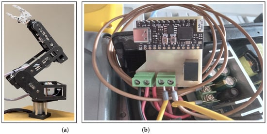
Figure 8.
Optimized robotic arm energy-efficiency measurement system. (a) Optimized robotic arm. (b) Energy IoT.
For the analysis of energy consumption, it was proposed to evaluate the performance of the aluminum (Al) robot arm against the carbon fiber (CF) robot arm under the same movement scheme starting from its “Home” position during a period of 15 min with three different speeds: 1000 deg/min, 3000 deg/min, and 9000 deg/min. The speed values from a previous table were used as a basis (see Table 4). The values obtained for energy consumption in Watts (W), as well as the differences obtained in each test, are shown below (see Table 8).
Table 8.
Comparison table of values of energy consumption obtained using the IoT device.
Based on Equation (1) and the data of test 1 from Table 4 and Table 8, respectively, we proceeded to calculate the useful mechanical energy as a result of comparing the Al and CF robotic arms:
- Useful energy consumed by the CF robotic arm (): 45.10 W
- Total energy consumed by the Al robotic arm (): 45.67 W
- energy efficiency is ,
- and energy gain is .
The first experiment was performed at a joint speed of 1000 deg/min, obtaining an average energy consumption of 45.67 W and 45.10 W for the Al and CF arm, respectively, obtaining an energy gain of 1.25% for the CF arm. Figure 9 shows the comparison of consumption throughout the test.
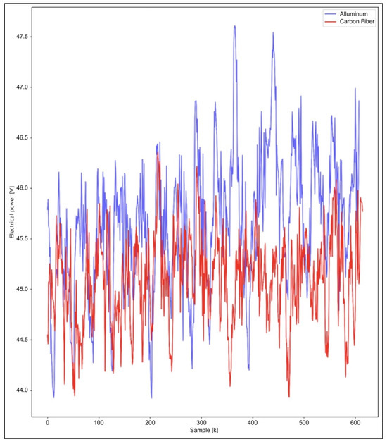
Figure 9.
Energy consumption of the Al vs CF robot arm at a combined speed of 1000 deg/min.
Similarly, based on Equation (1) and the data of test 2 from Table 4 and Table 8, respectively, we proceeded to calculate the useful mechanical energy as a result of comparing the Al and CF robotic arms:
- Useful energy consumed by the CF robotic arm (): 45.03 W
- Total energy consumed by the Al robotic arm (): 46.74 W
- energy efficiency is ,
- and energy gain is .
The second experiment was carried out at a joint speed of 3000 deg/min, obtaining an average energy consumption of 46.74 W and 45.03 W for the Al and CF arm, respectively, obtaining an energy gain of 3.66% for the CF arm. Figure 10 shows the comparison of consumption throughout the test.
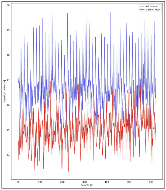
Figure 10.
Energy consumption of the Al vs. CF robot arm at a combined speed of 3000 deg/min.
Finally, based on Equation (1) and the data of test 3 from Table 4 and Table 8, respectively, we proceed to calculate the useful mechanical energy as a result of comparing the Al and CF robotic arms:
- Useful energy consumed by the CF robotic arm (): 46.78 W
- Total energy consumed by the Al robotic arm (): 48.03 W
- nergy efficiency is ,
- and energy gain is .
The third experiment was carried out at a joint speed of 9000 deg/min, obtaining an average energy consumption of 48.03 W and 46.78 W for the Al and CF arm, respectively, obtaining an energy gain of 2.59% for the CF arm. Figure 11 shows the comparison of consumption throughout the test.
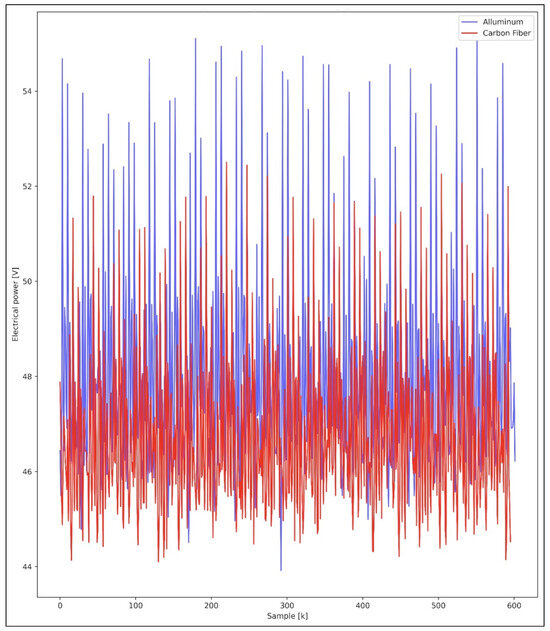
Figure 11.
Energy consumption of the Al vs. CF robot arm at a combined speed of 9000 deg/min.
4. Conclusions
According to the results of the simulation, it is recommended to manufacture carbon fiber parts, retaining the original thicknesses of the aluminum parts (4 mm). This is because if the thickness of the parts is reduced, the rigidity is also reduced, which could cause misalignment of the parts due to their bending. In addition to this, if the original thicknesses are respected, the assembly of the parts will have fewer complications. Using the carbon fiber/epoxy resin composite initially reduces the weight of the parts by 44.42%. Taking into account the results obtained, a mass reduction of approximately 54.6% is expected after optimization, while preserving the rigidity and resistance of the parts. The carbon fiber robotic arm turns out to be more efficient in energy consumption, achieving a maximum of 3.66% for tests carried out at a speed of 3000 degrees/min; the percentage value depends on the speed and torque required to move the joints.
Future research may encompass comparative analyses of different advanced materials such as graphene and titanium alloys, optimization of the design and configuration of the robotic arm to maximize the benefits of using carbon fiber, and detailed studies on the response of this material to dynamic loads and vibrations. In addition, the findings could be extrapolated to other sectors such as the automotive industry, aeronautics, and the development of medical prostheses, where weight reduction and energy consumption are crucial. Integration with IoT technologies and big data analytics also offers opportunities to optimize device performance in real time. Previous research, such as “High Efficiency Manufacturing With a Smart Carbon Fiber End Effector” [41] and “Optimization of energy consumption in industrial robots, a review” [42], have laid the groundwork for understanding the benefits of these materials, and the present research seeks to delve deeper into the dynamic behavior of carbon fiber joints, with the potential to transform multiple industries.
Author Contributions
Conceptualization, E.A.F.-U. and A.T.-M.; methodology, E.A.F.-U. and A.T.-M.; software, A.T.-M. and E.J.-T.; validation, A.T.-M., E.J.-T. and D.B.-P.; formal analysis, A.T.-M., E.J.-T. and D.B.-P.; investigation, A.T.-M., E.J.-T. and D.B.-P.; resources, E.A.F.-U.; data curation, E.J.-T. and D.B.-P.; writing—original draft preparation, A.T.-M. and E.J.-T.; writing—review and editing, E.A.F.-U. and A.T.-M.; visualization, A.T.-M.; supervision, E.A.F.-U.; project administration, A.T.-M. and E.A.F.-U.; funding acquisition, E.A.F.-U. All authors have read and agreed to the published version of the manuscript.
Funding
This research was funded by the CIDESI Research Center, México. Also, by the Mexican science council CONAHCYT grant number QID029/QID036.
Institutional Review Board Statement
Not applicable.
Informed Consent Statement
Not applicable.
Data Availability Statement
The data presented in this study are available on request from the corresponding author. The raw data supporting the conclusions of this article will be made available by the authors on request.
Acknowledgments
The authors are grateful for the support received from the CIDESI Research Center, Mexico, and also to the Mexican Science Council CONAHCYT, as the work described in this document is the result of the research project number QID029/QID036.
Conflicts of Interest
The authors declare no conflicts of interest.
Abbreviations
The following abbreviations are used in this manuscript:
| CONAHCYT | National Council for Humanities, Science, and Technology |
| CIDESI | Center for Engineering and Industrial Development |
| CFRP | Carbon-fiber-reinforced polymer |
| FEA | Finite element analysis |
| IoT | Internet of Things |
| CF | Carbon fiber |
| Al | Aluminum |
References
- Siar, M.V.S.; Fakharian, A. Energy efficiency in the robot arm using genetic algorithm. In Proceedings of the 2018 8th Conference of AI & Robotics and 10th RoboCup Iranopen International Symposium (IRANOPEN), Qazvin, Iran, 10 April 2018; pp. 14–20. [Google Scholar]
- Michalos, G.; Spiliotopoulos, J.; Makris, S.; Chryssolouris, G. A method for planning human robot shared tasks. CIRP J. Manuf. Sci. Technol. 2018, 22, 76–90. [Google Scholar] [CrossRef]
- Pål, Y.; Gjerstad, T.; Lien, T.K.; Nyen, P.A. Mapping energy consumption for industrial robots. In Proceedings of the Leveraging Technology for a Sustainable World: Proceedings of the 19th CIRP Conference on Life Cycle Engineering, University of California at Berkeley, Berkeley, CA, USA, 23–25 May 2012; Springer: Berlin/Heidelberg, Germany, 2012; pp. 251–256. [Google Scholar]
- Foumani, M.; Gunawan, I.; Smith-Miles, K.; Ibrahim, M.Y. Notes on Feasibility and Optimality Conditions of Small-Scale Multifunction Robotic Cell Scheduling Problems with Pickup Restrictions. IEEE Trans. Ind. Inform. 2015, 11, 821–829. [Google Scholar] [CrossRef]
- Iqbal, J.; Ul Islam, M.; Abbas, S.; Khan, A.A.; Ajwad, S. Automating industrial tasks through mechatronic system—A review of robotics in industrial perspective. Teh. Vjesn. 2016, 23, 917–924. [Google Scholar] [CrossRef]
- Mori, M.; Fujishima, M.; Inamasu, Y.; Oda, Y. A study on energy efficiency improvement for machine tools. CIRP Ann. 2011, 60, 145–148. [Google Scholar] [CrossRef]
- Goman, V.; Prakht, V.; Kazakbaev, V.; Dmitrievskii, V. Comparative Study of Energy Consumption and CO2 Emissions of Variable-Speed Electric Drives with Induction and Synchronous Reluctance Motors in Pump Units. Mathematics 2021, 9, 2679. [Google Scholar] [CrossRef]
- Pedersen, S.M.; Fountas, S.; Blackmore, S. Agricultural Robots—Applications and Economic Perspectives. In Service Robot Applications; Takahashi, Y., Ed.; IntechOpen: Rijeka, Croatia, 2008; Chapter 21. [Google Scholar] [CrossRef]
- Björkenstam, S.; Gleeson, D.; Bohlin, R.; Carlson, J.S.; Lennartson, B. Energy efficient and collision free motion of industrial robots using optimal control. In Proceedings of the 2013 IEEE International Conference on Automation Science and Engineering (CASE), Madison, WI, USA, 17–21 August 2013; pp. 510–515. [Google Scholar] [CrossRef]
- Aziz, M.; Yahya, S.; Almurib, H.; Abakr, Y.A.; Moghavvemi, M.; Madibekov, Z.; Elmahrouky, A.; Abdulrazic, M. Torque Minimized Design of a Light Weight Three Degrees of Freedom Planar Manipulator. IEEE Trans. Ind. Appl. 2019, 55, 3207–3214. [Google Scholar] [CrossRef]
- Borges, M.U.; Pinto, F.A.A.; Lima, E.J. Analysis of Energy Consumption in a Two-arm Vertical Planar Robot by Varying a Dimensionless Design Construction Parameter. In Proceedings of the 2019 19th International Conference on Advanced Robotics (ICAR), Belo Horizonte, Brazil, 2–6 December 2019; pp. 308–311. [Google Scholar] [CrossRef]
- Gadaleta, M.; Pellicciari, M.; Berselli, G. Optimization of the energy consumption of industrial robots for automatic code generation. Robot. Comput. -Integr. Manuf. 2019, 57, 452–464. [Google Scholar] [CrossRef]
- Wang, X.; Zhang, D.; Zhao, C.; Zhang, P.; Zhang, Y.; Cai, Y. Optimal design of lightweight serial robots by integrating topology optimization and parametric system optimization. Mech. Mach. Theory 2019, 132, 48–65. [Google Scholar] [CrossRef]
- Saidur, R. A review on electrical motors energy use and energy savings. Renew. Sustain. Energy Rev. 2010, 14, 877–898. [Google Scholar] [CrossRef]
- Visinka, R. Energy efficient three-phase AC motor drives for appliance and industrial applications. In Green Electronics/Green Bottom Line; Elsevier: Amsterdam, The Netherlands, 2000; pp. 29–42. [Google Scholar]
- Yang, A.; Pu, J.; Wong, C.B.; Moore, P. By-pass valve control to improve energy efficiency of pneumatic drive system. Control. Eng. Pract. 2009, 17, 623–628. [Google Scholar] [CrossRef]
- Gadaleta, M.; Berselli, G.; Pellicciari, M. Energy-optimal layout design of robotic work cells: Potential assessment on an industrial case study. Robot. Comput. -Integr. Manuf. 2017, 47, 102–111. [Google Scholar] [CrossRef]
- Riazi, S.; Bengtsson, K.; Wigström, O.; Vidarsson, E.; Lennartson, B. Energy optimization of multi-robot systems. In Proceedings of the 2015 IEEE International Conference on Automation Science and Engineering (CASE), Gothenburg, Sweden, 24–28 August 2015; pp. 1345–1350. [Google Scholar] [CrossRef]
- Jiang, P.; Wang, Z.; Li, X.; Wang, X.V.; Yang, B.; Zheng, J. Energy consumption prediction and optimization of industrial robots based on LSTM. J. Manuf. Syst. 2023, 70, 137–148. [Google Scholar] [CrossRef]
- Pupăză, C.; Constantin, G.; NEGRILĂ, S. Computer aided engineering of industrial robots. Proc. Manuf. Syst. 2014, 9, 87–92. [Google Scholar]
- Bugday, M.; Karali, M. Design optimization of industrial robot arm to minimize redundant weight. Eng. Sci. Technol. Int. J. 2019, 22, 346–352. [Google Scholar] [CrossRef]
- Sahu, S.; Choudhury, B. Static analysis of a 6-axis industrial robot using finite element analysis. Int. J. Mech. Eng. Technol. 2017, 8, 49–55. [Google Scholar]
- Zhou, J.; Yang, Z.; Chen, S. Analysis of the harvesting robot arm modal based on CAE. J. Chem. Pharm. Res. 2014, 6, 669–673. [Google Scholar]
- Yao, P.; Zhou, K.; Lin, Y.; Tang, Y. Light-Weight Topological Optimization for Upper Arm of an Industrial Welding Robot. Metals 2019, 9, 1020. [Google Scholar] [CrossRef]
- Yin, H.; Huang, S.; He, M.; Li, J. An overall structure optimization for a light-weight robotic arm. In Proceedings of the 2016 IEEE 11th Conference on Industrial Electronics and Applications (ICIEA), Hefei, China, 5–7 June 2016; pp. 1765–1770. [Google Scholar] [CrossRef]
- Yin, H.; Liu, J.; Yang, F. Hybrid Structure Design of Lightweight Robotic Arms Based on Carbon Fiber Reinforced Plastic and Aluminum Alloy. IEEE Access 2019, 7, 64932–64945. [Google Scholar] [CrossRef]
- Shanmugasundar, G.; Sivaramakrishnan, R.; Meganathan, S.; Balasubramani, S. Structural Optimization of an Five Degrees of Freedom (T-3R-T) Robot Manipultor Using Finite Element Analysis. Mater. Today Proc. 2019, 16, 1325–1332. [Google Scholar] [CrossRef]
- Sha, L.; Lin, A.; Zhao, X.; Kuang, S. A topology optimization method of robot lightweight design based on the finite element model of assembly and its applications. Sci. Prog. 2020, 103, 0036850420936482. [Google Scholar] [CrossRef] [PubMed]
- Carabin, G.; Wehrle, E.; Vidoni, R. A Review on Energy-Saving Optimization Methods for Robotic and Automatic Systems. Robotics 2017, 6, 39. [Google Scholar] [CrossRef]
- Denkena, B.; Bergmann, B.; Lepper, T. Design and optimization of a machining robot. Procedia Manuf. 2017, 14, 89–96. [Google Scholar] [CrossRef]
- Hirschtick, J. SOLIDWORKS and SW Data Management System Requirements. 2024. Available online: https://www.solidworks.com (accessed on 10 June 2024).
- Robotics, D. Industrial Automation Solutions, Within Reach. 2024. Available online: https://dorna.ai (accessed on 18 June 2024).
- Fernández, F.; Zverev, M.; Garrido, P.; Juárez, J.R.; Bilbao, J.; Agüero, R. Even Lower Latency in IIoT: Evaluation of QUIC in Industrial IoT Scenarios. Sensors 2021, 21, 5737. [Google Scholar] [CrossRef] [PubMed]
- Choe, C.; Choe, M.; Sungwook, J. Run Your 3D Object Detector on NVIDIA Jetson Platforms:A Benchmark Analysis. Sensors 2023, 23, 4005. [Google Scholar] [CrossRef]
- Londoño, P. Qué es Python, Para Qué Sirve y Cómo se Usa (+ Recursos Para Aprender). 2023. Available online: https://blog.hubspot.es/website/que-es-python (accessed on 14 June 2024).
- AWS. Adopte la IA Generativa de Forma rápida y Segura; Amazon Science—Artificial Intelligence in AWS: Amazon Web Services. 2024; p. 15. Available online: https://d1.awsstatic.com/psc-digital/2024/gc-400/security-gen-ai-ebook/4-biggest-questions-about-generative-AI-security-ebook-ES-XL.pdf (accessed on 21 July 2024).
- Abaqus. Abaqus/CAE; Dassault Systèmes. 2024. Available online: https://www.3ds.com/products/simulia/abaqus/cae (accessed on 21 July 2024).
- ASTMB209:2021; Standard Specification for Aluminum and Aluminum-Alloy Sheet and Plate. ASTM International: West Conshohocken, PA, USA, 2021. [CrossRef]
- AMS4015:2023; Aluminum Alloy, Sheet and Plate 2.5 Mg–0.25Cr (5052-O) Annealed. SAE International: Warrendale, PA, USA, 2023. [CrossRef]
- Vega-Leal, C.; Zárate-Pérez, C.; Gomez-Culebro, V.A.; Burelo, M.; Franco-Urquiza, E.A.; Treviño-Quintanilla, C.D. Mechanical recycling of carbon fibre reinforced polymers. Part 1: Influence of cutting speed on recycled particles and composites properties. Int. J. Sustain. Eng. 2024, 17, 1–10. [Google Scholar] [CrossRef]
- Chun, C.; Guerra-Zubiaga, D.A.; Bailey, G.; Bharadwaj, K. High Efficiency Manufacturing with a Smart Carbon Fiber End Effector. In Proceedings of the ASME International Mechanical Engineering Congress and Exposition, Columbus, OH, USA, 30 October–3 November 2022; American Society of Mechanical Engineers: New York, NY, USA, 2022; Volume 86649, p. V02BT02A016. [Google Scholar]
- Soori, M.; Arezoo, B.; Dastres, R. Optimization of energy consumption in industrial robots, a review. Cogn. Robot. 2023, 3, 142–157. [Google Scholar] [CrossRef]


Disclaimer/Publisher’s Note: The statements, opinions and data contained in all publications are solely those of the individual author(s) and contributor(s) and not of MDPI and/or the editor(s). MDPI and/or the editor(s) disclaim responsibility for any injury to people or property resulting from any ideas, methods, instructions or products referred to in the content. |
© 2024 by the authors. Licensee MDPI, Basel, Switzerland. This article is an open access article distributed under the terms and conditions of the Creative Commons Attribution (CC BY) license (https://creativecommons.org/licenses/by/4.0/).