Abstract
The present study analyzes the behavior of connections with flange-web welded plates using the finite element method in tubular columns filled with concrete, and beam, type I. An analytical study of the structural dynamic behavior of a Special Moment Frame (SMF) was carried out, in 5 levels, with HEB structural profiles, for IPE-type columns and beams, according to the requirements established by the AISC-360-16, ANSI-341 standards, and the Ecuadorian standard NEC-2015. The design process of the special frame structure was validated with the help of specialized software. Subsequently, the structural profiles were replaced following the actual construction situation in Ecuador. 3D models of the structural system and the elements of metallic connections were obtained for evaluation through the analysis of finite elements. These models were subjected to virtual tests according to the AISC 341-16 protocols and FEMA 350 standards. The evaluation of the connections showed that they did not meet the flexural strength criterion at 0.04 rad, but they exceeded of the plastic moment at rad. Thus, flange-web welded plate connections can be valid for intermediate moment frames (IMF) in areas with moderate seismicity. In addition, it was observed that the columns filled with concrete optimize the structural elements in terms of dimensions; but do not contribute significantly to soldered connections due to the later development of plastic ball joints.
1. Introduction
Although the concept of a special moment frame (SMF) is a relatively recent development in international building codes, steel moment-resisting frames have been applied for over a hundred years in construction [1].
In recent decades, the structural methods for calculating and constructing these steel structures have been constantly updated to meet the needs and challenges generated by new projects [2,3]. Therefore, building codes, such as AISC 360-16 [4], AISC 341-16 [5], and AISC 358-16 [6], have adopted a design philosophy aimed at providing greater safety to avoid collapse induced by earthquakes of different magnitudes.
Diaphragm connections are also often used in SMF to ensure structural safety [7,8,9]. In this context, regulations such as AISC-358 [6] include several pre-qualified connections. When a connection is not prequalified, specific tests are required and it must pass the seismic design criteria for SMF buildings, specified in AISC 341 [5], including connections with external diaphragms.
Wu et al. [10] analyzed the seismic behavior of a joint composed of steel beams and steel-reinforced concrete columns (MPCJ). These authors studied three types of connections: bolted, welded, and bolted-welded beam-column. The connections were subjected to a low cycle with inverse load, to investigate the elastic-elastoplastic development, the failure characteristics, and the seismic response. Results showed bending failure at the end of the beam following the buckling of the flange connection plate. The research found stable hysteretic curves, strength and stiffness degradation, good ductility, and energy dissipation performance.
Today, in civil construction, the demand for special moment frames is greater, due to their good dissipation response to seismic events and their versatility in complex applications. The foundation systems become more economical with these frames because they impose smaller forces on the foundation [7,8,11].
SMFs comprise three basic elements: beams, columns, and beam-column connections. Concrete-filled tubular Steel Columns (CFSTC) are widely used in complex architectural proposals for their load-bearing capacity under several conditions [12]. CFSTCs and steel-reinforced concrete columns are extensively used in current steel-structure residential projects [13,14], combining the respective advantages of concrete and steel. Many in-depth studies on these structures have been conducted [15,16]. In [17] it is reported on experimental and finite element research of three full-scale Wall Concrete-Filled Steel Tubular Columns (WCFSTCs). Studies have established that this structure exhibits an attractive energy dissipation capacity and beneficial seismic performance.
Due to their geometry, structural tubular or hollow section profiles are currently one of the most effective in terms of resistance to axial compression load. Among the advantages of such structures are larger radii of gyration compared to open profiles of similar dimensions, ease of production, adequate design versatility, and a greater polar moment of inertia. However, in the Ecuadorian construction sector, these do not comply with the corresponding regulations, which puts the safety and stability of the structures at risk. In Ecuador, steel constructions are increasingly common in buildings for different purposes: housing, shopping centres, etc., however, these present fillet welds that do not adequately conform to the recommendations to generate rigidity (consult, for example, in http://biblioteca2.ucab.edu.ve/anexos/biblioteca/marc/texto/AAT6499.pdf (accessed on January 2024)).
The AISC-358 [6] standard governs metallic connections, and it also describes the limitations, scope, and requirements to apply this type of links, so that the structures can work stably in the inelastic range and adequately dissipate energy. However, many structures currently built do not conform to such regulations. Fillet welding is applied instead of full penetration welding (as required by the regulations) [18]. Steel connections are the most expensive items, so the total cost of a structure is affected by the type of connection you apply. For this reason, this is usually an influential factor in the decision on the model to apply models, seeking simplicity and lower costs [19].
After the 2011 earthquake in the Tohoku region, Japan, it was found that structures with rigid beam-column connections, in moment frames, with tubular columns and I-type beams, adequately resisted this event (consult, for example, in https://repositorio.uchile.cl/handle/2250/147494 (accessed on January 2024)). However, it has been documented in different investigations that these connections are weak and can present fractures that result in significant damage, in the event of events such as earthquakes or similar, if they are not correctly implemented [1,20].
Ecuador is a country located in a region of high seismic risk, and for safety, it is essential to study the behavior of construction systems and their connections. The results of these studies will provide the national market with connection options for tubular, concrete-filled, circular, and rectangular column sections, that promote simple assembly, reduce total costs, and increase the process efficiency. Particularly, the connection of steel beam with tubular steel column, filled with concrete, using flange-web welded plate connection, has not been fully studied in the country.
In this context, the article reports on a study of the seismic behavior of flange-web welded plate connections in tubular columns filled with concrete and type I beam, by simulation with the finite element method. For this, the SMF is analyzed, under the guidelines of the AISC/ANSI 360-341 [4,5] standards, and a study of its inelastic behavior against cyclic loads. Four metallic connections were analyzed in different configurations with CFST columns, connected with steel beams.
For example, in [21,22] it is reported tests for six different types of circular CFST welded connections, using the quasi-static test method. The connections were fabricated using different elements: diaphragms, plates, embeddable weldable corrugated bars, continuous flanges, and continuous steel tubes. On the other hand, Cheng, C.T. and Chung, L. performed tests under cyclic loading on five circular CFST welded connections [23]. These authors tested four types of connections, characterized by the arrangement of the weld from the flange of the beam to the external diaphragm, and by the tubular walls of the columns. The obtained results showed that all the connections failed due to the fracture of the weld during the non-linear behavior. The residual stresses accumulated in the tube wall because of diaphragm welding, reducing the deformation capacity of the column.
In this investigation, three-dimensional connections were modeled and analyzed until failure. In this case, for the AISC 358-16 code for seismic applications, only two prequalified connections are considered, which use tubular columns (ConXL and SidePlate) that have a high cost in the market. There are no known recommendations for obtaining rigid connections such as those proposed in this study, which allow the generation of plastic hinges to obtain stable hysteretic curves.
2. Materials and Methods
2.1. Case Study
The case study has been formulated following the Ecuadorian Construction Standard (NEC-2015 [24]) guidelines to obtain the design spectrum and analyze the 2D frame system. Table 1 summarizes the data for the study.

Table 1.
Parameters to obtain the design spectrum, according to NEC-2015.
Construction of the Design Spectrum for the Case Study
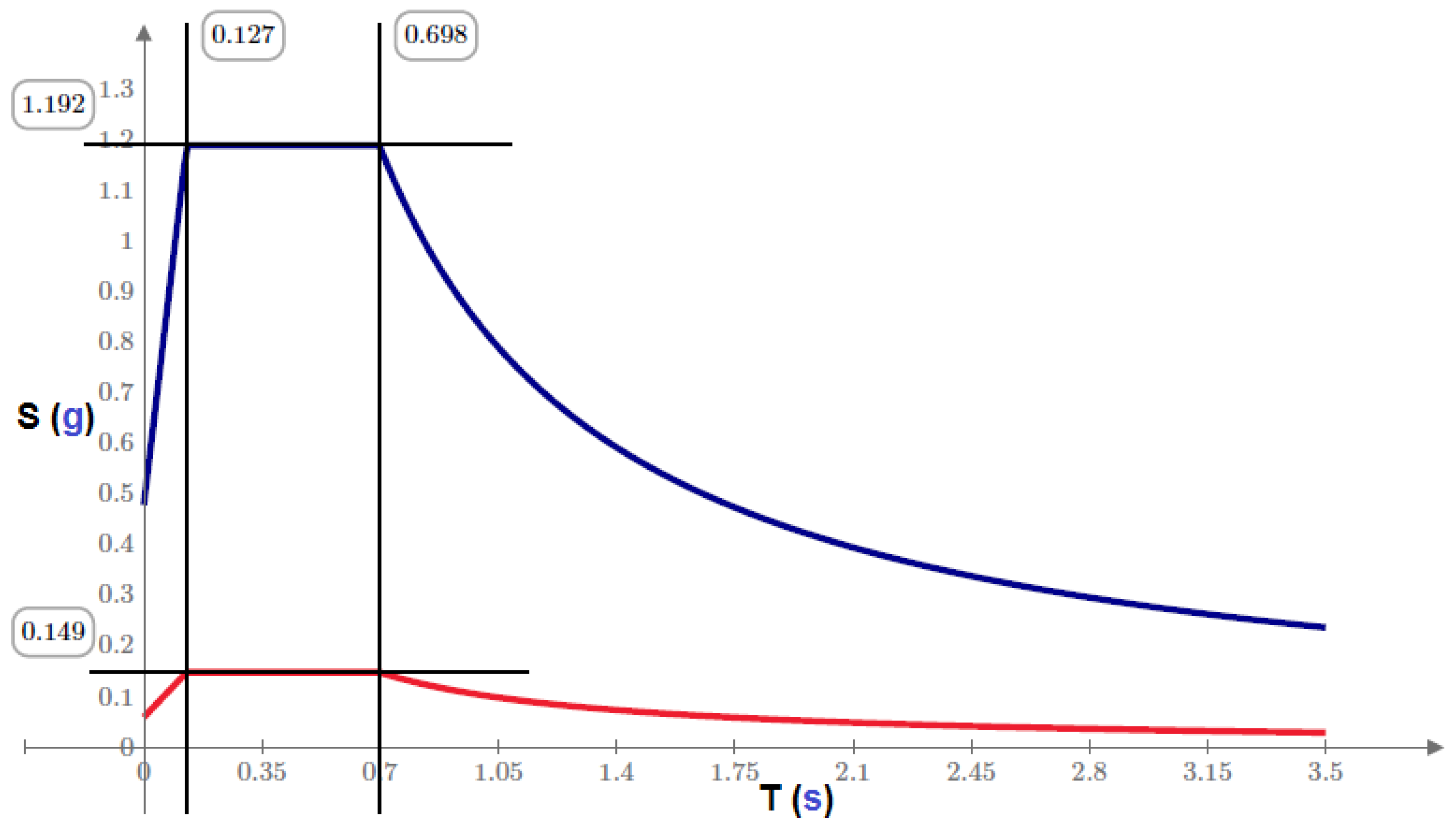
The acceleration spectrum consists of an elastic and an inelastic configuration. The latter is reduced with the corresponding response coefficient. The elastic response spectrum of accelerations is expressed as a fraction of the acceleration of gravity, for the design earthquake levels. Equations (1)–(3) represent the slopes of the elastic response spectrum (blue curve in Figure 1) only for vibration modes other than the fundamental one.
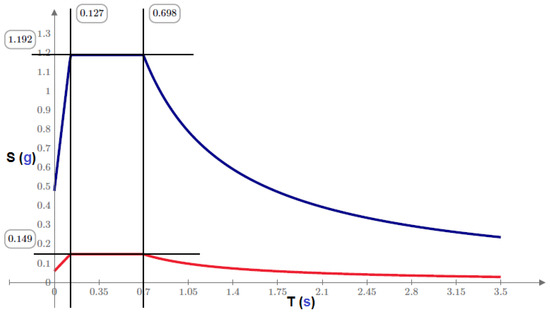
Figure 1.
Elastic response spectrum of accelerations (curve in blue) and inelastic response spectrum of accelerations (curve in red).
The forces obtained through dynamic elastic analysis can be reduced for design purposes by dividing by the corrected R-value and multiplying by importance factor I (in expression (4): left factor for the curve in blue, right factor for the curve in red). Therefore, a spectrum of reduced accelerations can be considered (red curve in Figure 1).
The above graph and expressions have been obtained directly from the output of MATHCAD 7.00 software (trial version), under regulation 2.-NEC-SE-DS-Seismic-Hazard-part-1, article 3.3.1: Spectrum horizontal elastic design in accelerations.
For the structural system, the main geometries have been considered, with the formulations below, used to deduce the static basal shear.
Once the vibration periods of the structure are obtained, it is done the calculation of spectral accelerations. The case of the study considered holds that and the static basal shear is determined for the direction in X, by the following equation:
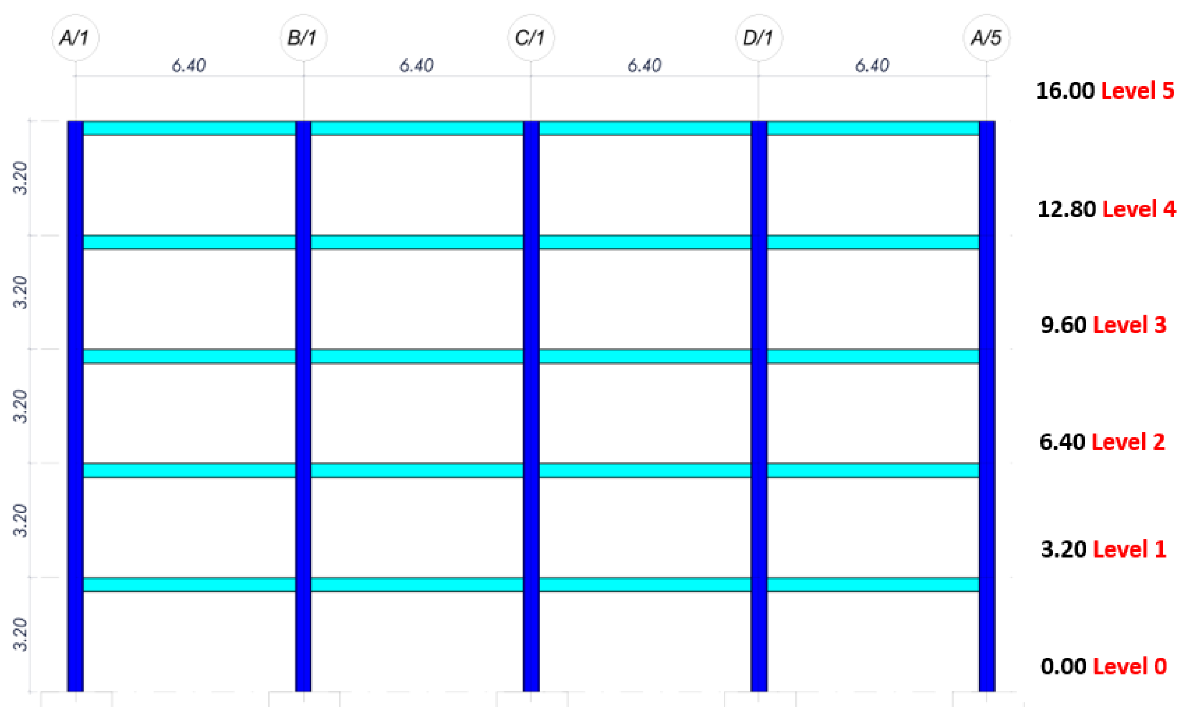
The geometry of the 2D portico is presented below and consists of 5 floors, three sections, a length between sections of m (Length), and a floor height of m (Height) (Figure 2).

Figure 2.
Geometry of the 2D frame for structural design. Units in meters.
For the analytical calculation process, columns and beams were assigned to the 2D frame (Figure 2). The following loading system was applied:
: Horizontal Quake.
: Notional Load of permanent load in X direction.
: Notional Load of variable load in X direction.
A mass source was applied with variable load participation , according to the specifications of the NEC-2015 [24] for general cases. Table 1 describes the seismic action established by local regulations. For the irregularities and coefficients of structural configuration (Art. 5.3, NEC-2015), the irregularity in elevation was obtained , . And the irregularity in height , . For the basal cut (Art. 6.2.2, b), NEC-2015), a value of was obtained. The load combinations were applied according to the standard AISC-360 [4]. The P-delta effect was considered, and rigid arms allowed for providing rigidity to the connections of the frame type elements in beams and columns, with a factor of . As a result of the analytical calculation, the modal values were obtained as follows: for the first mode of vibration, a period of s; for the second a period of s; for the third, a period of s; for the fourth mode a period of s; and the fifth one, a period of s. Mass participation reached . The seismic design of columns and beams was also carried out, as well as the review of the local buckling of the elements. Plastic hinges were defined, and the ratio of moments in the joints was calculated. With the validation of the calculations analytically obtained, building proposals were designed, which include tubular columns, to identify an adequate connection for this type of structuring.
3. Connection Models
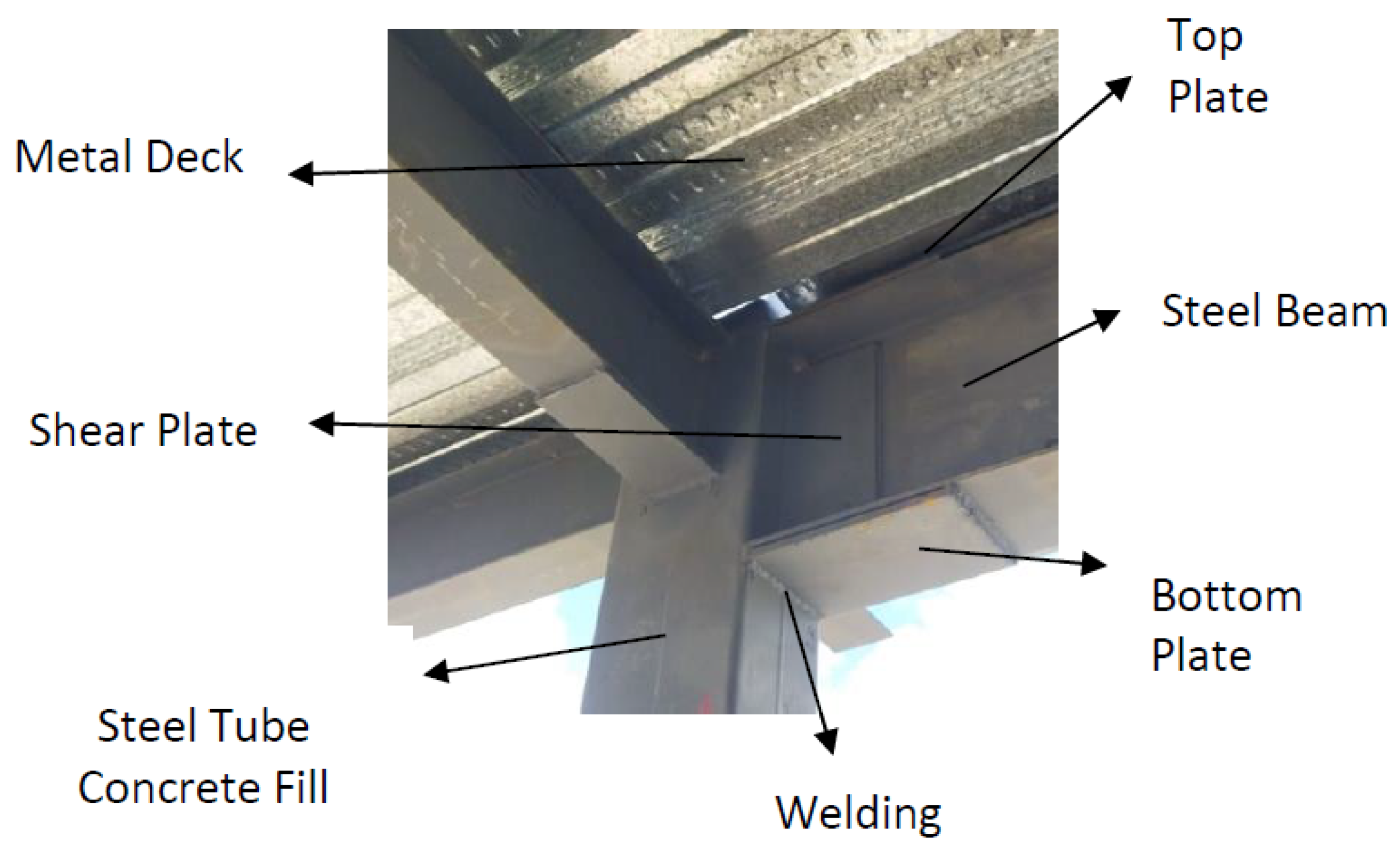
A beam-column connection is appreciated in various buildings, where welded plates are applied in the flange and the web. In [19] it is stated that, for this type of connection, “the external plates greatly stiffen the column walls, avoiding distortion of the cross-section, and the stress concentrations in the connection are greatly decreased, which translates into an adequate structural behaviour of the connection against local faults and brittle faults”. In Ecuador, a specific project has been developed, in which connections are applied (see Figure 3). However, no detailed study validates whether it effectively meets the requirements of a rigid or partially rigid connection.

Figure 3.
Construction details of the connection.
Geometric Description of the Connections
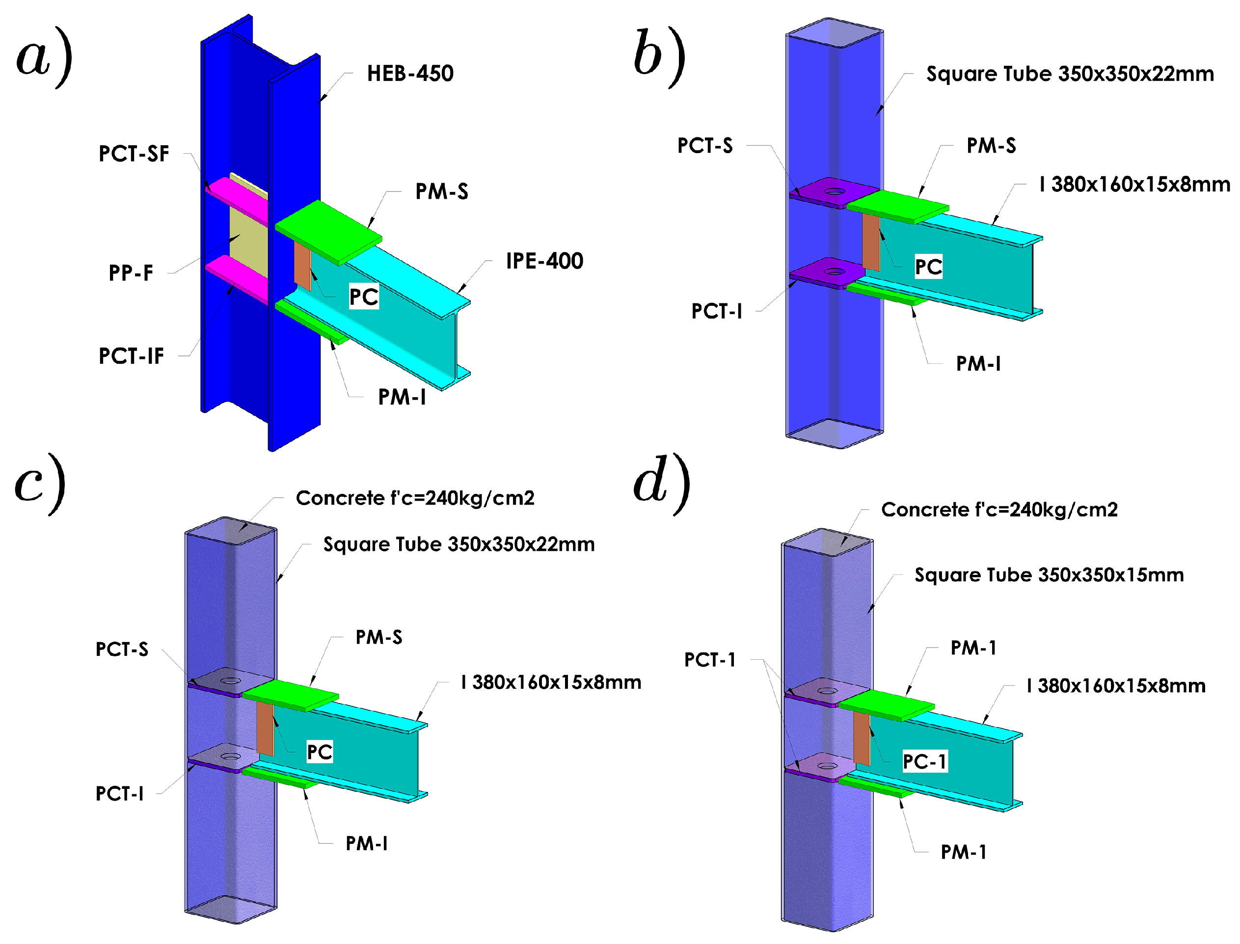
According to the configuration of structural models of buildings, four types of connections have been considered for finite element analysis. It should be clarified that the union of the plates that make up the connection is considered CJP full penetration welding. However, the analysis of the weld seams is omitted to highlight the parts that make up the connection.
Nomenclature for connection elements:
- PM-S: top moment plate;
- PM-I: bottom moment plate;
- PC: shear plate;
- PCT-SF: front top continuity plate;
- PCT-IF: front bottom continuity plate;
- PCT-SP: back top continuity plate;
- PCT-IP: back bottom continuity plate;
- PP-F: front panel plate;
- PP-P: back panel plate;
- PCT-S: top continuity plate;
- PCT-I: bottom continuity plate.
For the first model, the 1-A connection type is considered, whose elements are described in Table 2 and shown in Figure 4a.
Table 2.
Description of the 1-A connection’s elements set.

Figure 4.
Connection’s elements: (a) connection 1-A; (b) connection 2-A; (c) connection 2-B; (d) connection 3-A.
For the second model, the 2-A connection type is considered, whose elements are described in Table 3 and shown in Figure 4b.
Table 3.
Description of the 2-A connection’s elements set.
For the third model, the 2-B connection type is considered, whose elements are described in Table 4 and shown in Figure 4c.
Table 4.
Description of the 2-B connection’s elements set.
In the table above, and hereinafter, represents the compressive strength of concrete. For the fourth model, the 3-A connection type is considered, whose elements are described in Table 5 and shown in Figure 4d.
Table 5.
Description of the 3-A connection’s elements set.
4. Simulation of Materials’ Mechanical Properties
For the simulations, the ANSYS WORKBENCH 2021 R1 software was used.
The von Mises yield criterion with the kinematic hardening rule was adopted to model the plates of the steel tubes and beams. This model simulates the plasticity behavior of steel under cyclic loading. For the concrete material, with , was also modeled with the kinematic hardening rule, for the finite element analysis, according to the study presented in [25]. The kinematic hardening rule model is also used in finite element analysis, according to [26]. The Solid65 element in the ANSYS program was used to model the concrete. This element is suitable for representing solids with or without reinforcements and can simulate the cracking and crushing of concrete. Studies reveal that the William-Warnker model [27] can be adopted as a failure criterion for concrete filling in columns and slabs, and nine parameters are required as inputs to describe the model. The tension-stress relationship of Han [28] was simplified as a multi-linear model, which was used for column-filled concrete. Therefore, for the concrete material with , the multi-linear model was applied for the finite element analysis (see Table 6).
Table 6.
Stress vs. Strain.
4.1. Boundary Conditions
To determine the behavior of the connections, restrictions were considered for the degrees of freedom in beams and columns, according to the experimental schemes in which the tests are carried out in the test bench ([6,7,29]).
In Figure 5 it can be seen, in the test bench, that the column element is considered embedded, and at the upper end of the beam, the required cyclical displacements are generated with the help of hydraulic pistons. In the central part of the beam, two lateral bars prevent lateral torsional buckling.
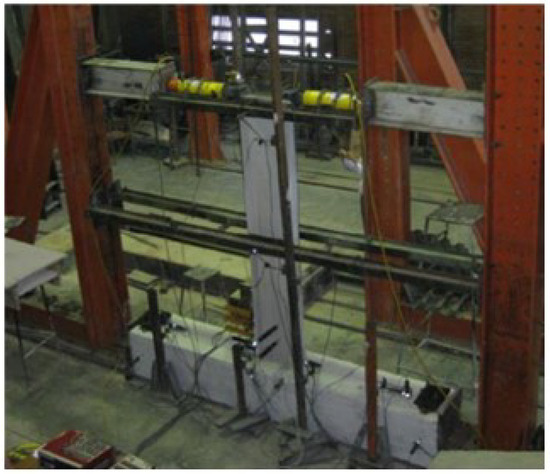
Figure 5.
Full-scale test bench of the WUF-W connection with square section column.
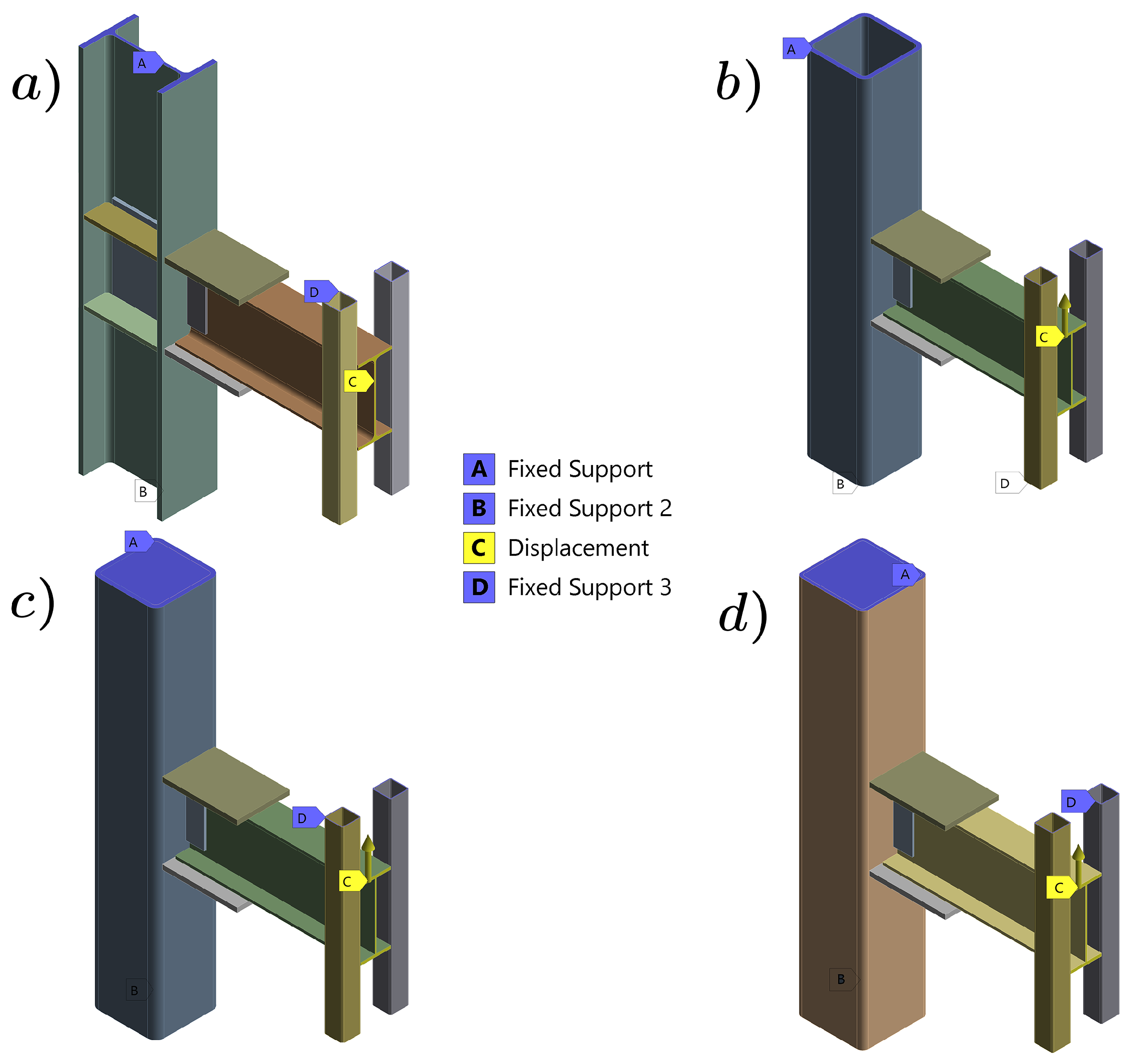
The edge conditions in the experimental testing bench can be seen in Figure 6, illustrating the restrictions imposed on the different connections.

Figure 6.
Boundary conditions: (a) Connection 1-A. (b) Connection 2-A. (c) Connection 2-B. (d) Connection 3-A.
4.2. Displacement Protocol
The displacement protocol was established according to the AISC 341-16 [5] standard, chapter K2, and FEMA 350, chapter 3.9.1. Angular values are established to determine if the connection can resist moments in a system subjected to load cycles: Special Moment Frame (SMF) [6]. See Table 7.
Table 7.
Loading protocol according to AISC 341-16 and FEMA 350 standards.
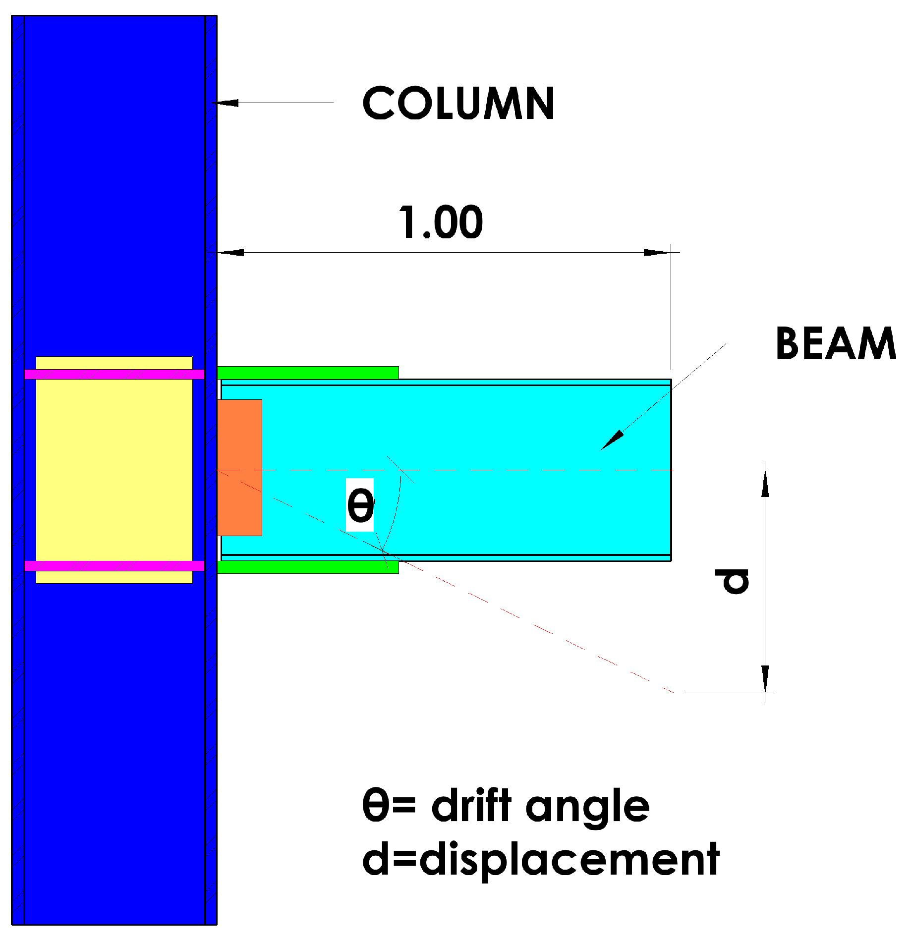
In ANSYS simulations, rotation angles should be expressed as displacements for input. For this, a m beam length was considered (Figure 7).
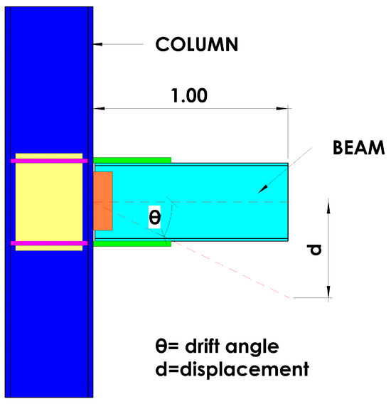
Figure 7.
Detail of the beam-column system.
The displacement protocol used in the analysis of the seismic behavior of the beam-column connection is based on the AISC 358 standard(consult, for example, in the American Institute of Steel and Construction (AISC). AISC 358-16: Prequalified Connections for Special and Intermediate Steel Moment Frames for Seismic Applications: Chicago, IL, USA, 2016, https://www.aisc.org/globalassets/aisc/publications/standards/A358-16W.pdf (accessed on January 2024), which establishes procedures to evaluate connections in steel structures under seismic loads. This protocol consists of applying linear cyclic displacements, divided into 8 discrete steps (see Table 8) to simulate the action of seismic events. This allows evaluation of the connection response to cyclic loads, reflecting energy absorption and recovery of the structure’s shape.
Table 8.
Relation of drift angles to length.
Therefore, the displacement curve was entered into the ANSYS WORKBENCH 2021 R1 software.
4.3. Element Meshing
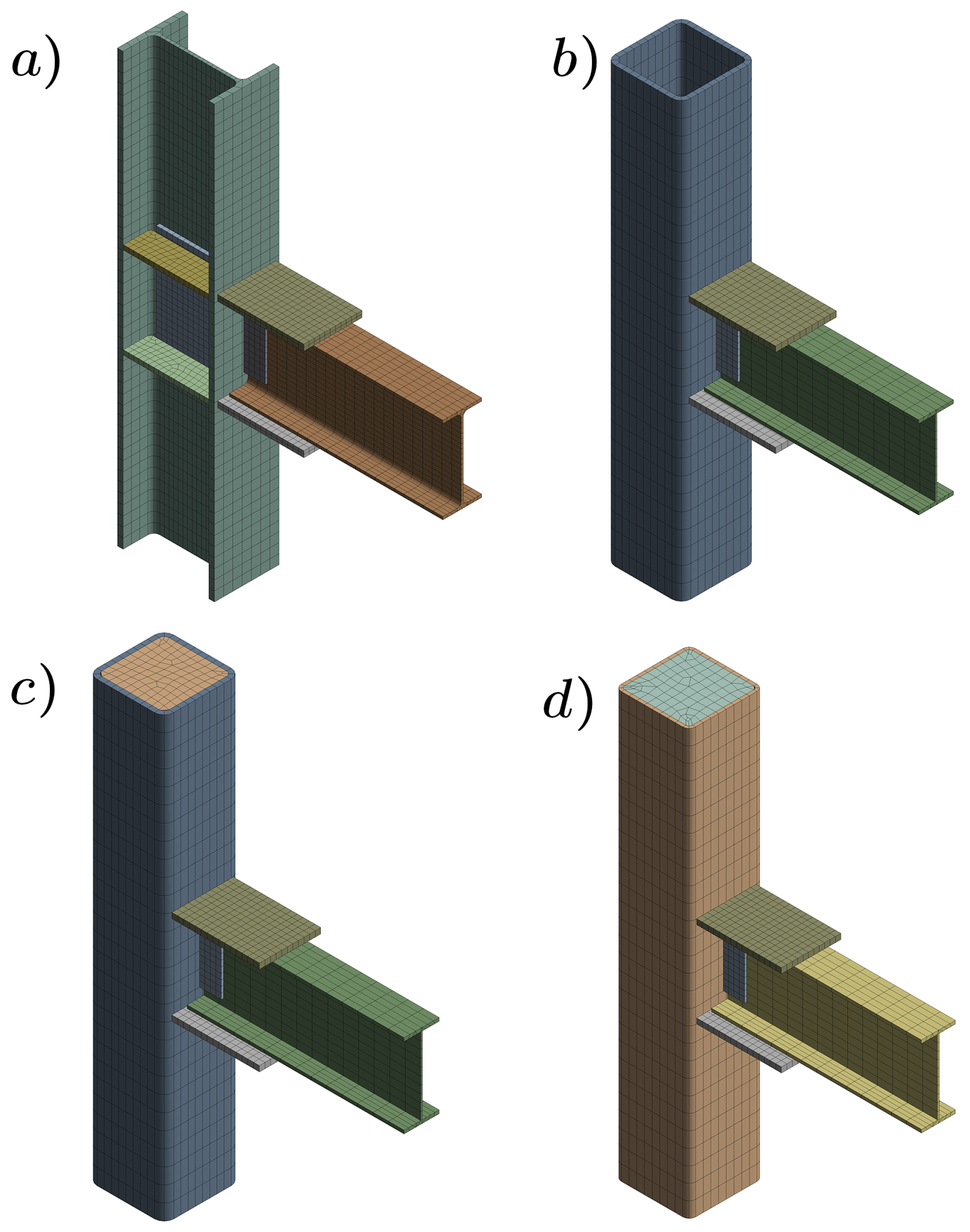
The characteristics of the mesh for each connection and the number of elements and nodes that make up them are described in Table 9. These element size values in the connection body guarantee a error convergence.
Table 9.
Meshing characteristics for each connection.
The mesh configuration for each model can be seen in Figure 8.

Figure 8.
Connection mesh: (a) 1-A, (b) 2-A, (c) 2-B, (d) 3-A.
4.4. Interface between Steel Tube and Concrete Core
For the present study, the interface between the steel tube and the concrete core was modeled with a perfect joint condition in the finite element analysis (Figure 9). This means that the absence of longitudinal slip between the concrete and the steel tube is assumed, thus simplifying the simulation process and facilitating the analysis of the transfer of forces between these materials. As the joint is considered perfect, the anchor bolts (studs) cannot prevent longitudinal slip during simulation. However, these bolts efficiently transmit transverse tensile forces between the steel pipe and the concrete. Several studies have shown that anchor bolts can impact the distribution of stresses and deformations in concrete that has been filled [30]. This aspect is challenging to measure experimentally, but computational models can be used to investigate it [25].
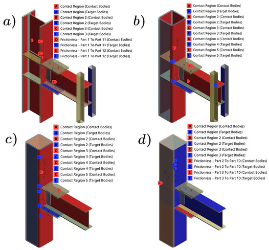
Figure 9.
Bonded type contact for the four connections: (a) 1-A, (b) 2-A, (c) 2-B, (d) 3-A.
Another aspect considered was adding sidebars (with friction-less type contact), which prevent friction between the contact faces of the beam and the bars. Supports and restraints were modeled to represent the experimental arrangement [6,7,29], providing lateral support and preventing beam twisting of the beam. The displacement protocol was implemented at the end of the beam. (see Figure 10).
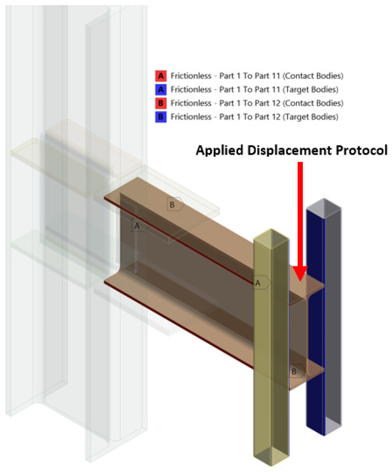
Figure 10.
Friction less-type contact between beam and bar, and the application of the displacement protocol.
4.5. Expansion on Practical Implications
Different strategies for finite element models provide a comprehensive analysis of the structural behavior of composite connections, but they have drawbacks. Limitations in accurately reflecting the interaction and fracture of welded connections arise from the simplified representation of the weld in many cases [25]. Furthermore, the relationship between the steel column and the concrete core is often assumed to be a perfect joint, ignoring longitudinal slip and affecting the simulation accuracy. Regarding the interaction between different materials, such as steel and concrete, the model often overlooks the complexity of force transfer or material degradation under cyclic loading. Simulation of the materials and connections failure is also limited, as it does not accurately capture the actual behavior of the structure under seismic loading conditions. In addition, the task may require a considerable amount of computational resources, which could limit its practicality in certain scenarios [26]. Finally, the lack of comprehensive experimental analysis to validate the model may further limit its accuracy. Together, these limitations highlight the need to combine computational simulations with experimental tests to reflect, more closely to reality, the structural behavior under seismic conditions.
In this study, the use of different integral methodologies is idealized for a connection proposal that is being applied in the industrial sector of Ecuador. Implementing experimental tests is very expensive, so validation would be a phase to be developed later. Optimizing connection designs for seismic resilience can be achieved by comparing different alternatives. Seismic resilience refers to the structure’s ability to resist, absorb and recover from the effects of a seismic event [31]. The article emphasizes the seismic performance of composite structures made of concrete-filled steel columns (CFSTCs) and reinforced steel beams. These structures are capable of dissipating energy and avoiding catastrophic failures.
To complement the proposal of the computational models analyzed, it has been achieved that they can reflect energy dissipation, that is, the fuse elements are primarily beams and reinforcement plates.
Currently in Ecuador, not all projects are carried out with prequalified connections, due to their high costs. The standard practice for single-family housing structures involves welding the beam directly to the column [32]. Therefore, the work does not prioritize optimization since implementing plates in connections increases total weight by . The scope of this simulation proposal is to define for which type of moment-resistant frame adequate behavior is obtained according to the requirements established in the ANSI/AISC 341-16 standard [5].
4.6. Connection Analysis
This section presents the results obtained in the simulations of the cyclic loads, and the structural behavior is determined based on the forces and displacements. The response is evaluated “moment vs. rotation” hysteresis curves. Another point of analysis is the Von Mises stress distribution, which allows for estimating the maximum stresses generated in the connections.
Qualification Conditions
It is necessary to determine the maximum moment expected in the plastic hinge to evaluate the hysteresis diagrams. The maximum moment was calculated for the four types of connections and the following information was obtained.
According to AISC 341-16 [5], the requirements for a beam-column connection of an SMF are:
- The connection must support a rotation of at least rad due to the displacement between levels.
- The measured flexural strength of the connection, calculated on the face of the column, must be at least Mp of the connected beam for a rotation of rad. (Mp: Plastic Moment)
On the other hand, for an intermediate moment frame (IMF) beam-column connection, the requirements are the following:
- The connection must support a rotation of at least rad due to the displacement between levels.
- The measured flexural strength of the connection, calculated on the face of the column, must be at least Mp of the connected beam for a rotation of rad.
5. Results and Discussion
5.1. Description of the Connection
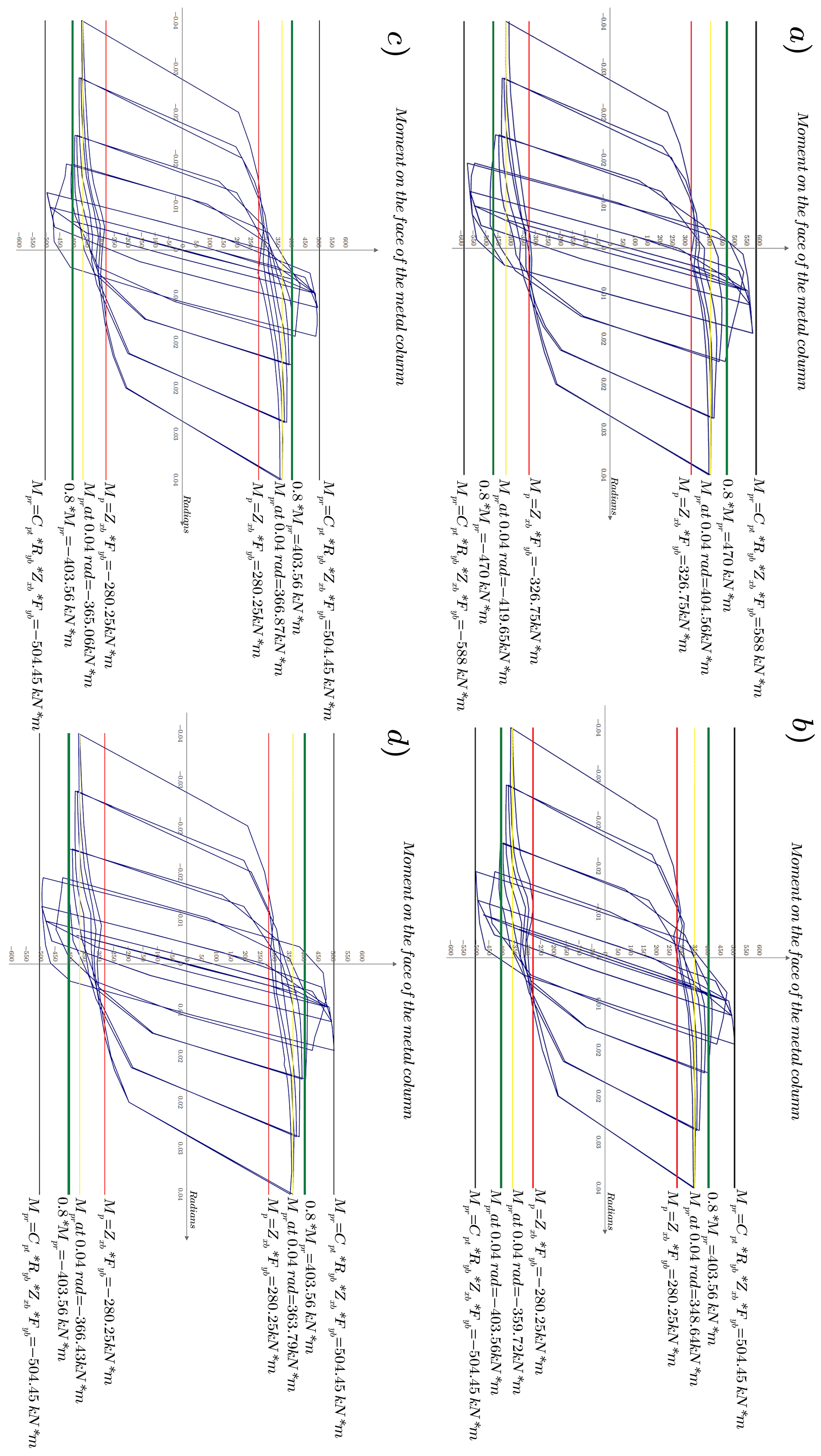
The graphs below depict the relationship between the bending moment applied to the connection and the resulting rotation angle in the beam. The hysteresis curves were obtained from a finite element analysis developed with the help of the WORKBENCH 2021 R1 software, imposing the boundary conditions detailed in Figure 8 and Figure 9. Similar calibrations were also applied in [32,33,34]. The hysteresis curve illustrates the connection’s response to cyclic loading, indicating its strength, stiffness, and energy dissipation capabilities. The slope of the curve in the first phase corresponds to the initial stiffness of the connection. The slope decreases as the load increases and the structure deforms, indicating stiffness degradation throughout the loading cycles. The area bounded by the hysteresis curve reflects the capacity of the connection to dissipate seismic energy. The connection absorbs energy while undergoing loading cycles, preventing this energy from being transmitted to other parts of the structure and protecting the overall integrity of the frame. It is observed that the resistance of the connection at radians is kNm, a value greater than the yielding moment of the beam. It reflects the structure’s ability to absorb seismic energy by resisting significant deformations before reaching plasticizing. Table 10 shows the analytical values of the plastic moment of each type of connection. The Mp value corresponds to the nominal plastic moment of the beam section.
Table 10.
Analytical plastic moment for each connection type.
The 1-A beam-column connection experiences a maximum moment at rad, which is equivalent to of Mp. It means that the material is close to its limit of deformation, but still has some capacity to resist additional forces. At rad, the maximum moment in the connection drops to of Mp, reflecting the degradation of its strength as the connection experiences greater angular deformations. This also implies a reduced ability to dissipate seismic energy, as the connection absorbs energy as it undergoes loading cycles, but its ability to do so decreases as its stiffness degrades (Figure 11a).
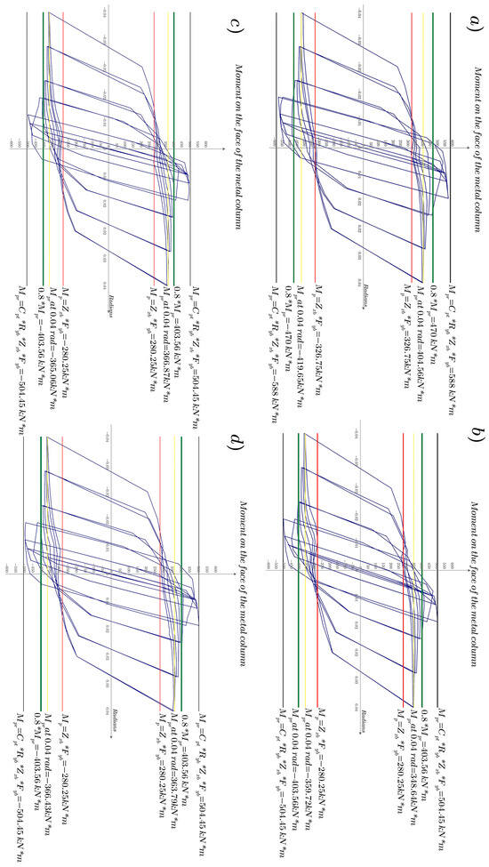
Figure 11.
Hysteretic curve (moment–curve): (a) for connection 1-A; (b) for connection 2-A; (c) for connection 2-B; (d) for connection 3-A.
At rad, the maximum moment generated in connection 2-A is of Mp, meaning that the connection is close to its yielding limit but still retains some capacity to resist additional deformations. At rad, the maximum moment in the connection is of Mp, reflecting the degradation of the connection strength as it experiences greater angular deformations. This illustrates a progressive reduction in stiffness, the ability to resist cyclic loading, and the ability to dissipate seismic energy (Figure 11b).
5.2. Plastification Mechanism
This section analyzes the failure location in the connection elements, which exceed the yield limit and enter the inelastic range. In all simulations, a plastic hinge forms at a greater distance from the location of the moment plates. Generation of local buckling is also observed, both in the flanges and in the soul of the beam.
- Connection Analysis 1-A.
In Figure 12a, a maximum stress at rad of MPa is observed, while in Figure 13a, at rad, the maximum stress is MPa. Local buckling is generated in the web of the beam.
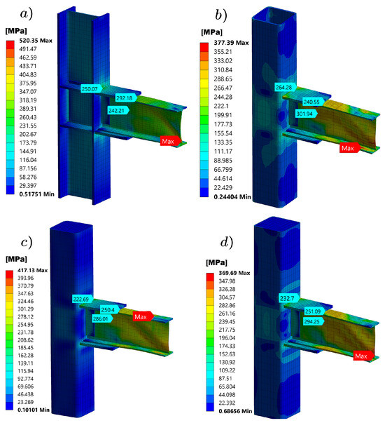
Figure 12.
Plastic hinge location in connections at rad: (a) 1-A; (b) 2-A; (c) 2-B; (d) 3-A.
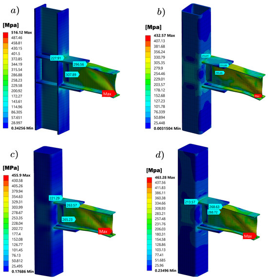
Figure 13.
Plastic hinge location in connections at rad: (a) 1-A; (b) 2-A; (c) 2-B; (d) 3-A.
- Connection Analysis 2-A.
In Figure 12b, a maximum stress is observed, at rad, of MPa, while in Figure 13b, at rad, the maximum stress is MPa. Local buckling is generated in the web of the beam.
- Connection Analysis 2-B.
In Figure 12c, a maximum stress is observed, at rad, of MPa, while in Figure 13c, at rad, the maximum stress is MPa. Local buckling is generated in the web of the beam.
- Connection Analysis 3-A.
In Figure 12d, a maximum stress is observed, at rad, of MPa, while in Figure 13d, at rad, the maximum stress is MPa. Local buckling is generated in the web of the beam.
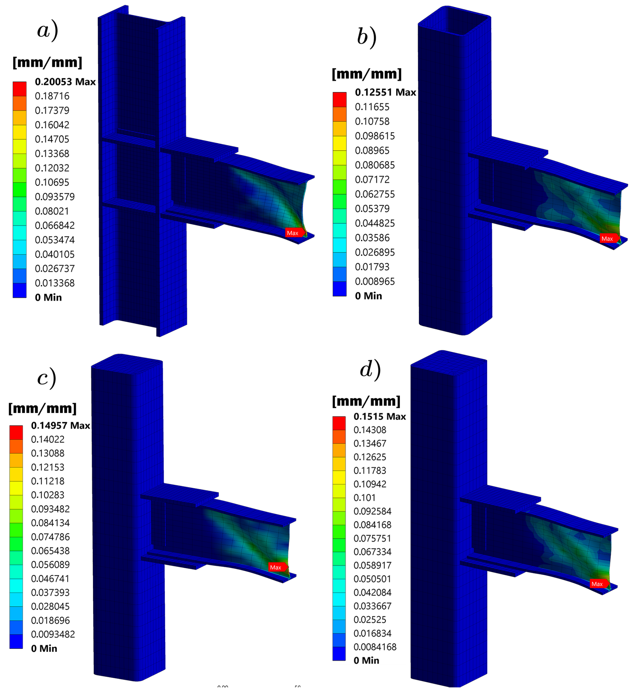
The type of connection proposed guarantees that the plastic hinge is concentrated in an area of the beam exceeding the value mm. This is evidence of the generation of a fuse element, following what the ANSI/AISC 341-16 [5] standard established, which specifies that the column and the connection must not fail.
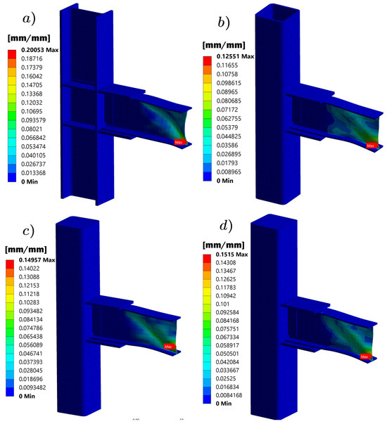
Figure 14.
Equivalent plastic strain: (a) connection 1-A; (b) connection 2-A; (c) connection 2-B; (d) connection 3-A.
The generation of the plastic mechanism in beam-to-tubular column connections filled with concrete, using external diaphragms, is crucial to guarantee good seismic performance of the structure. For the study reported in [34], the plastic mechanism is located 480 mm from the face of the column, which allows energy dissipation and reduction of seismic loads transfer to the global structure. This point is critical due to the high concentration of inelastic stresses and deformations. The present study examines welded connections to the flanges and webs of the beams, where the plastic mechanism is also formed after the welded plates, helping to maintain structural integrity and efficiently dissipate energy. In both cases, the importance of the location and design of the plastic mechanism is highlighted, to optimize the energy dissipation capacity and improve the ductility of the connection. Advantages include high energy dissipation capacity, good ductile behavior, and high initial stiffness. However, there are also disadvantages, such as complexity in construction, higher costs due to the need for precise welds and high-quality materials, complicated maintenance, and the possible need for repairs after an earthquake. In summary, both connection configurations are effective in dissipating seismic energy and exhibit good ductility, although practical implementation and associated costs vary. The choice between them will depend on project-specific factors, such as the availability of materials and technical capacity to perform complex welds.
Furthermore, modeling the plasticity mechanism using the finite element method is a complex and demanding task. Extreme precision in the material properties representation and boundary conditions is required to capture adequately the nonlinearity of connections under cyclic loading. This process includes the creation of detailed meshes that can faithfully reflect the areas of stress and deformation concentration, as well as the kinematic hardening models implementation to represent the inelastic behavior of steel and concrete. Numerical simulation must carefully validate experimental results to ensure that model predictions are accurate and reliable. The complexity of FEM modelling increases the time and computational resources required but is indispensable for designing connections that can meet stringent seismic performance requirements.
6. Conclusions
In this study on the seismic behavior of welded plate connections in the flanges and web, in concrete-filled tubular columns, four types of connections were evaluated under cyclic loading, using the finite element method. The results revealed that none of the connections meet the flexural strength criterion at rad. Still, all exceeded of the plastic moment at rad, valid for an intermediate frame (IMF) type building in areas of moderate seismicity.
Connection 1-A reached a maximum plastic moment of at rad, and at rad, respectively; with a plastic deformation of and a maximum Von Mises stress of MPa at rad. Connection 2-A reached a maximum plastic moment of at rad, and at rad, respectively; with a plastic deformation of and a maximum stress of MPa at rad. Connection 2-B reached a maximum plastic moment of at rad and at rad, respectively; with a plastic deformation of and a maximum stress of MPa at rad. Finally, connection 3-A reached a maximum plastic moment of at rad, and at rad, respectively; with a plastic deformation of and a maximum stress of MPa at rad.
The increase in SMF systems motivates the use of new connections that are not approved according to current design regulations. Therefore, it is necessary to research to ensure that the frames are designed to absorb seismic energy in the beams without affecting the connections. Under this context, this work presents a numerical model and an analysis of the inelastic behavior under cyclic loads of a steel beam—rectangular steel tubular column connection, filled with concrete, using plates.
New research could be aimed at increasing the portfolio of connecting steel beams to rectangular tubular columns, also made of steel, filled with concrete, using external diaphragms and analyzing different configurations, that is, column sections, beam profiles and types of concrete suitable for earthquake-resistant applications. In some works, the validation of new connections has already been reported, such as that of a steel beam to a tubular steel column filled with concrete using external diaphragms, leading to the definition of the finite element analysis methodology, corroborated by an experimental protocol. Therefore, the methodology applied in this computational study compiles all the estimates used in real cases and taken to a virtual environment [34].
Future research could also study the pinching effect in screw connections in more detail. Additionally, diaphragms could be connected to the column wall using full penetration welds with 45-degree angles. It would be worth considering whether full penetration and partial penetration welds can be combined to reduce manufacturing time and costs, despite the increase in computational cost.
In the design process of the building alternatives, with tubular profiles with and without concrete filling, the demand capacity of the structures and the floor drifts was guaranteed to comply with the NEC-SE-DS [24] standard and the specifications of the AISC-360 [4] standard.
Priority was given to optimizing the structural elements, both columns and beams, which allow operating with smaller sections than those used in the frame design with type I laminated profiles. Thus, an efficient structure with less weight in its structural elements is established.
The strong column-weak beam criterion prevented the columns from entering the inelastic range and prevented plastic hinges from developing in the beams, thus preventing energy dissipation. The columns filled with concrete turned out to be the most effective, since the moment ratio reached the highest values compared to the other models.
To establish the connection, the team considered the prequalified bolted flange plate (BFP) connection, referencing the AISC 358-16 [6] standard. The calculation and sizing analyses of the upper and lower plates of the skids, as well as their respective shear plate, were extracted from the specifications provided for the welded connection in the proposal.
The analysis of the von Mises stress allowed us to determine that the elements enter the plastic range, specifically the wing and the flanges of the beam, posterior to the area where the plates welded to the flange are located. This can also be evidenced in the plastic deformation analysis, which provides the area where the core is plasticizing at rad.
Based on the results obtained, it is concluded that the columns filled with concrete allow the structural elements to be optimized, specifically in the sizing of the thickness of the tubular columns. Still, they do not generate a greater contribution to the type of connection with welded plates evaluated, since, due to the very shape of the connection, the development of the plastic hinges occurs after the welded plates. With the help of the analysis of the hysteretic curve in the different types of connections, it was obtained that all of them do not meet the bending resistance criterion at rad, and are below of the plastic moment. However, at rad, the value of of the probable moment is exceeded. Thus, the connections with welded plates, both in the flange and the web, are validated for an intermediate moment frame (IMF) type building, optimal for areas of moderate seismicity.
The proposal analyzes the types of connections used in construction, which do not comply with AISC 358-16 regulations [6]. These connections would be used in intermediate moment frames (IMF). It has also been verified that these connections do not respond adequately to SMF frames, according to the protocol specified in the AISC 341-16 regulations [5].
Considering the current reality of the construction sector, metal connections must comply with strict regulations to guarantee structural safety during seismic events. Pre-qualified connections, such as those described in ANSI/AISC 358-16 [6], are essential for structures that must operate in the inelastic range and adequately dissipate energy. In Ecuador, many structures do not comply with these regulations due to the application of fillet welds instead of full penetration welds, which could compromise the rigidity and safety of the connections.
If a connection is desired to be used in a special moment frame system, the best option would be the 3-A connection which has superior performance in terms of plastic moment and plastic deformation, and this suggests a greater capacity to dissipate energy and resist deformations under severe seismic loads. Although no connection completely meets the rad criterion, connection 3-A offers the best overall performance, proving to be the most suitable for applications in SMF systems where more robust and resistant behavior is expected.
Author Contributions
D.F.C.-M. and I.S.V.-S.: review of the state of the art, analytical structural dynamic analysis of the frame, preparation of 3D models, analysis and calibration of the models for finite element analysis, and evaluation of results. F.P.M.-M.: analytical structural dynamic analysis of the frame, evaluation of results, and project management. P.B.T.-J.: analysis of information, analytical structural dynamic analysis of the frame, evaluation of results, and text review. E.V.-S.: preparation and writing of the manuscript, translation. All authors have read and agreed to the published version of the manuscript.
Funding
The Salesian Polytechnic University, Cuenca, Ecuador, supported this research through the Master’s Program in Mechanical Engineering, with mention in the Design of Metal Structures in Civil and Industrial Works, RPC-SO-24-No.540-2020.
Institutional Review Board Statement
Not applicable.
Informed Consent Statement
Informed consent was obtained from all subjects involved in the study. Written informed consent has been obtained from the patient(s) to publish this paper.
Data Availability Statement
Data referenced in this article are included in this article’s.
Acknowledgments
The authors of this work appreciate the support provided by the Research Group on New Materials and Transformation Processes (GIMAT) in developing the research processes.
Conflicts of Interest
The authors declare no conflicts of interest.
References
- Hamburger, R.; Krawinkler, H.; Malley, J.O.; Adan, S.M. NIST GCR 09-917-3; Seismic Design of Steel Special Moment Frames: A Guide for Practicing Engineers; US Department of Commerce and The National Institute of Standards and Technology (NIST): Washington, DC, USA, 2009.
- Hamburger, R.O. Recommended Seismic Design Criteria for New Steel Moment-Frame Buildings; Federal Emergency Management Agency (FEMA) Bulletin: Washington, DC, USA, 2000.
- Roeder, C.; Venture, S. State of the Art Report on Connection Performance; Federal Emergency Management Agency (FEMA) Bulletin: Washington, DC, USA, 2000.
- American Institute of Steel and Construction (AISC). Specification for Structural Steel Buildings; AISC: Chicago, IL, USA, 2005. [Google Scholar]
- AISC 341-16; Seismic Provisions for Structural Steel Buildings. AISC: Chicago, IL, USA, 2016.
- AISC 358-16; Prequalified Connections for Special and Intermediate Steel Moment Frames for Seismic Applications. AISC: Chicago, IL, USA, 2016.
- Li, W.; Xu, L.F.; Qian, W.W. Seismic performance of concrete-encased CFST column to steel beam joints with different connection details. Eng. Struct. 2020, 204, 109875. [Google Scholar] [CrossRef]
- Wang, Z.B.; Tao, Z.; Li, D.S.; Han, L.H. Cyclic behaviour of novel blind bolted joints with different stiffening elements. Thin-Walled Struct. 2016, 101, 157–168. [Google Scholar] [CrossRef]
- LRFD, A. Specification for Structural Steel Buildings; American Institute of Steel Construction: Chicago, IL, USA, 2016. [Google Scholar]
- Wu, C.; Yu, S.; Liu, J.; Chen, G. Development and testing of hybrid precast steel-reinforced concrete column-to-H shape steel beam connections under cyclic loading. Eng. Struct. 2020, 211, 110460. [Google Scholar] [CrossRef]
- Andrade, C. Steel I-Beam Connections Qualification Connected to Column Weak Axis. Ph.D. Thesis, Universidad Nacional de Colombia, Bogotá, Colombia, 2015. [Google Scholar]
- Ceron, C. Prequalification of a Beam-Column Moment Welded Connection with Dog Bone Section Reduction in the Beam for Metal Buildings under the Action of Dynamic Loading. Ph.D. Thesis, Universidad del Valle Cali, Buga, Colombia, 2011. [Google Scholar]
- Gan, D.; Zhou, Z.; Zhou, X.; Hai Tan, K. Seismic behavior tests of square reinforced concrete–filled steel tube columns connected to RC beam joints. J. Struct. Eng. 2019, 145, 04018267. [Google Scholar] [CrossRef]
- Gan, D.; Yan, F.; Yang, Z.; Zhou, Z.; Cheng, R. Behavior of CFST column to concrete-filled U-shaped steel beam joints with slabs under cyclic loading. J. Struct. Eng. 2022, 148, 04021299. [Google Scholar] [CrossRef]
- Gan, D.; He, Z.; Huang, H. Investigation of cyclic behavior of full-scale tree-like hollow structural section columns with infilled concrete. J. Constr. Steel Res. 2022, 194, 107339. [Google Scholar] [CrossRef]
- Skalomenos, K.A.; Hatzigeorgiou, G.D.; Beskos, D.E. Parameter identification of three hysteretic models for the simulation of the response of CFT columns to cyclic loading. Eng. Struct. 2014, 61, 44–60. [Google Scholar] [CrossRef]
- Sun, X.; Hao, J.; Xue, Q.; Fan, C.; Liu, H.; He, M. Experimental study on seismic behavior of walled concrete-filled steel tubular columns. Jianzhu Jiegou Xuebao/J. Build. Struct. 2018, 39, 92–101. [Google Scholar] [CrossRef]
- Bowen Cruzatty, S.P. Estudio del Comportamiento de la Conexión Viga Columna Precalificada de ala Soldada sin Refuerzo y Alma Soldada (Wuf-w) en un Edificio de Estructura Metálica. Ph.D. Thesis, Universidad de Guayaquil-Facultad de Ciencias Matemáticas y Físicas, Guayaquil, Ecuador, 2020. [Google Scholar]
- Valadez, A.A.L.; Rionda, S.B. Simulación numérica de conexiones metálicas Trabe-Columna por el método de los elementos finitos. Jóvenes en la Cienc. 2016, 2, 985–989. [Google Scholar]
- Tapia Hernández, E.; Santiago Flores, A.; Guerrero Bobadilla, H.; Chávez Cano, M.M. Comportamiento experimental de conexiones de marcos de acero ante demandas sísmicas. In Ingeniería Sísmica; Sociedad Mexicana de Ingeniería Sísmica AC, Number 103: Mexico City, Mexico, 2020; pp. 37–55. [Google Scholar]
- Schneider, S.P.; Alostaz, Y.M. Experimental behavior of connections to concrete-filled steel tubes. J. Constr. Steel Res. 1998, 45, 321–352. [Google Scholar] [CrossRef]
- Tao, Z.; Li, W.; Shi, B.L.; Han, L.H. Behaviour of bolted end-plate connections to concrete-filled steel columns. J. Constr. Steel Res. 2017, 134, 194–208. [Google Scholar] [CrossRef]
- Cheng, C.T.; Chung, L.L. Seismic performance of steel beams to concrete-filled steel tubular column connections. J. Constr. Steel Res. 2003, 59, 405–426. [Google Scholar] [CrossRef]
- Norma Ecuatoriana de la Construcción (NEC). Norma Ecuatoriana de la Construcción, actualización 2023; Ministerio de Desarrollo Urbano y Vivienda: Quito, Ecuador, 2015.
- Nie, J.; Qin, K.; Cai, C. Seismic behavior of connections composed of CFSSTCs and steel–concrete composite beams—Finite element analysis. J. Constr. Steel Res. 2008, 64, 680–688. [Google Scholar] [CrossRef]
- Chen, Z.; Qin, Y.; Wang, X. Development of connections to concrete-filled rectangular tubular columns. Adv. Steel Constr. 2015, 11, 408–426. [Google Scholar]
- William, K.J.; Warnke, E.P. Constitutive Model for the Triaxial Behavior of Concrete; International Association for Bridge and Structural Engineering Proceedings: Zurich, Switzerland, 1975. [Google Scholar]
- Han, L. Concrete Filled Steel Tubular Structures; China Science Press: Beijing, China, 2000. [Google Scholar]
- Nia, Z.S.; Ghassemieh, M.; Mazroi, A. WUF-W connection performance to box column subjected to uniaxial and biaxial loading. J. Constr. Steel Res. 2013, 88, 90–108. [Google Scholar]
- Cook, R.A.; Prevatt, D.O.; McBride, K.E. Steel Shear Strength of Anchors with Stand-Off Base Plates; Technical Report; Florida Department of Transportation: Tallahassee, FL, USA, 2013.
- Wang, H.; Hao, J.; Xue, Q.; Sun, X. Seismic behaviour of a wall-type concrete-filled steel tubular column with an end plate steel beam reinforced joint. Soil Dyn. Earthq. Eng. 2023, 173, 108142. [Google Scholar] [CrossRef]
- Bucheli García, J.A.; Cando Tipan, W.O.; Jaramillo de León, O.P. Análisis de una conexión metálica soldada entre una viga “I” y una columna tubular a escala reducida. RECIMUNDO Rev. Científica Investig. Conoc. 2018, 2, 302–324. [Google Scholar]
- Ramirez Ortiz, C.; Areiza Palma, G.; Gutierrez Amador, A.D.; Ramirez Duque, J.L.; Cano Buitron, R.E.; Gonzales Escobar, L.F. Seismic behavior of a steel beam-to-concrete-filled steel tubular column connection using external diaphragms. Appl. Sci. 2022, 12, 3618. [Google Scholar] [CrossRef]
- Ramírez Ortiz, C.; Gutierrez Amador, A.D.; Ramírez Duque, J.L. Numerical analysis of the seismic behavior of a steel beam-to-concrete-filled steel tubular column connection using external diaphragms. Buildings 2022, 12, 1217. [Google Scholar] [CrossRef]


Disclaimer/Publisher’s Note: The statements, opinions and data contained in all publications are solely those of the individual author(s) and contributor(s) and not of MDPI and/or the editor(s). MDPI and/or the editor(s) disclaim responsibility for any injury to people or property resulting from any ideas, methods, instructions or products referred to in the content. |
© 2024 by the authors. Licensee MDPI, Basel, Switzerland. This article is an open access article distributed under the terms and conditions of the Creative Commons Attribution (CC BY) license (https://creativecommons.org/licenses/by/4.0/).