Article

Quantitative Research on Roof Deformation and Temporary Support Stiffness in Deep-Mine Gob-Side Entry Retaining by Roof Cutting

1
State Key Laboratory of Coal Mine Safety Technology, CCTEG Shenyang Research Institute, Fushun 113000, China
2
School of Mining Engineering, Anhui University of Science and Technology; Huainan 232001, China
3
China Coal Research Institute (CCRI), Beijing 100000, China
*
Author to whom correspondence should be addressed.
Appl. Sci. 2024, 14(15), 6520; https://doi.org/10.3390/app14156520 (registering DOI)
Submission received: 20 June 2024 / Revised: 16 July 2024 / Accepted: 22 July 2024 / Published: 26 July 2024

Abstract

:
The important technical process to ensure the success of gob-side entry retaining by roof cutting (GERRC) was the advanced pre-splitting blasting to cut off the mechanical connection between the roadway and working face roof. The whole-cycle roof structure evolution and stress characteristics of GERRC were analyzed. The factors affecting the roof deformation of GERRC were analyzed, and the quantitative relationship between the roof deformation of GERRC and the support stiffness was determined. The results showed that the temporary support stiffness was higher, the support position to the side of the roof cutting was closer, and the roof subsidence deformation of GERRC was smaller. It is proposed to use a single support mass with a high stiffness to control the deformation of the roof, but it also made the support mass and roof elastic potential energy aggregate. To fully utilize the matching of the support stiffness and roof subsidence, improve the stability, and control the subsidence deformation of the roof in GERRC, double-row stacking supports were adopted in the inclination of GERRC, which were used to increase the stiffness of the support system.

1. Introduction

Gob-side entry retaining by roof cutting (GERRC) and pressure relieving is one of the effective technologies for the stable control of the roof in deep-mine gob-side entry retaining. The technical means is by implementing the directional energy accumulation pre-splitting of the roadway roof in advance of the working face, cutting or weakening the mechanical connection between the roadway roof and the working face roof. During the process of cutting the roof and retaining the roadway, large deformation anchor cables and high pre-tension anchor rods (cables) are used as basic support, and stacking support is generally used as temporary support. Gangue blocking mass is used to replace the filling mass next to the roadway, so as to automatically form the roadway after mining the working face [1] and eliminate the isolation coal pillars between the two working faces. The schematic diagram of GERRC is shown in Figure 1. The evolution of the roof structure in different mining stages of GERRC is different, and the stress and deformation of the retaining roof change accordingly [2].
Domestic and foreign scholars have conducted extensive research on the evolution of the roof structure in GERRC. He et al. [3,4] believe that GERRC transforms the “long cantilever beam structure” of the gob-side roadway roof into a “short cantilever beam structure” through advanced directional energy accumulation blasting. They simplify the stress of the short cantilever beam as uniformly distributed loads to calculate the roof deformation. Gao et al. [5,6] analyze the roof structure and stress characteristics of different stages of GERRC, simplifying the roof structure of different stages into fixed-end beams, simply supported beams, and cantilever beams. They analyze the deformation characteristics of the gob-side roadway roof and propose roof stability control technology for roadway formation. Yang et al. [7,8] focus on conditions where the rock strata are thin and the loose layer is thick. They simplify the thick loose layer as uniformly distributed loads and assume the thin rock strata as a good elastomer, establishing beam models for fixed-end, simply supported, and cantilever roofs. They analyze the roof deformation during roadway formation. Chen et al. [9,10] compare and analyze the roof structure and stress analysis of conventional gob-side entry retaining and GERRC, believing that advanced pre-splitting roof cutting can effectively reduce the cantilever length of the roadway side roof and reduce the additional load on the side support body. Guo et al. [11] investigate the roof deformation mechanism of self-formed roadways with cross-fault roof cutting and pressure relieving and verify that the “roof cutting and pressure relieving constant resistance anchor cable” support method has a good control effect on the roof deformation of cross-fault roadways. Liu et al. [12] believe that during GERRC, the immediate roof and main roof form a combined cantilever structure, and the roof subsidence deformation has a synergistic effect. The shear failure of the anchor bolt is used as the critical index to obtain the interlayer displacement criterion.
As the mining depth increases, the deformation of the roadway-surrounding rock also increases and becomes more intense, manifesting as roadway instability and even destructive rock burst, making roof management difficult and support costs high [13]. In terms of roof control in deep-mine roadways, Xie, He, and others [14,15] believe that when the mining depth generally exceeds the first critical depth, the mining rock mass medium is in a stage of large plastic deformation. They propose using roof-cutting and pressure-relieving technology to optimize the stress environment of the roadway-surrounding rock. In terms of support technology, it is necessary to consider the coupling of the support body and the surrounding rock in terms of strength, stiffness, and structure. Krzysztof Skrzypkowski [16] conducts comparative tests on the load capacity of three-point and four-point criteria, as well as their respective loading capacities under the condition of filling gangue. It is found that filling the three-point and four-point crib with gangue increases its maximal load several times compared to the empty cribs. The bonding characteristics of the TSL material formed a composite layer with the rock skin, thus increasing the specimen’s ability to resist rock skin failure, which can provide a method for reinforcing the surrounding rock of the roadway [17]. S. Sinha et al. [18] find in their study that shearing strands at pillar corners near the roof and floor are critical for failure initiation. Therefore, in roadway support, attention should be paid to the control at the pillar corners near the roof and floor of the roadway. Zuo et al. [19] propose the concept of equal-strength beam support for the roof of deep rectangular roadways, which means designing different support lengths of anchors for the same roadway section to achieve the uniform distribution of local stresses on the roof. Gao et al. [20] analyze the deformation mechanism of deep high-stress roadway-surrounding rock and propose a directional tensile blasting roof-cutting and pressure-relieving surrounding rock control technology for deep roadways. The technique actively controls the collapse position of the overburden structure to optimize the stress environment of the roadway. Zhao et al. [21] analyze the manifestation characteristics of mine pressure in the surrounding rock of thick hard roof direct overburden gob-side entry retaining in kilometer-deep mines and propose a comprehensive control technology for surrounding rock structure optimization that combines the optimization of roof caving in the advanced working face and the structural breaking and pressure relief of the roof on the gob side. Wang et al. [22] addressed the challenge of surrounding rock control in deep high-stress mining roadways, using the Sun Village Coal Mine as an engineering background. They analyzed and proposed a deep high-strength anchoring and grouting gob-side entry retaining method. This method uses high-strength anchoring and grouting to improve the integrity of the roadway roof and uses roof pre-splitting to cut off the stress transfer between the gob area and the roadway roof, placing the roadway in a stress-reduction zone.
In summary, GERRC uses advanced pre-splitting to cut off the physical and mechanical connection between the roadway roof and the working face roof, transforming the roadway roof from a long cantilever to a short cantilever beam structure during the retaining period. This reduces the supporting pressure of the roof and optimizes the stress environment of the retaining roadway roof. As the mining depth increases, the control of the roadway roof requires both pressure relief and improved coordination between the roadway internal support and roof subsidence deformation. This manuscript focuses on the roof deformation law of the GERRC and establishes the relationship between the roof and support stiffness, providing a theoretical basis for the calculation of gob-side entry retaining by roof cutting roof deformation and roof support.

2. Evolution Characteristics of the Roof Structure in Gob-Side Entry Retaining by Roof Cutting

2.1. Engineering Background

The 7135 working face of Qidong Coal Mine is the DF5-21 fault protection coal pillar in the east, the transportation uphill of the 71 coal No. 3 mining area in the west, the 7133 planned working face in the south, and the 7137 working face that has been mined in the north. The elevations of the working face are from −482 m to −565 m, the dip length is 175 m, the strike length is 1688 m, the average thickness of the coal seam in the working face is m = 3.3 m, the width of the roadway is b = 5.0 m, the height is h = 3.0 m, and the average dip angle of the coal seam is 12°. Above the working face is the old void area of the 6133 working face, with a normal distance of approximately 39 m. The average burial depth of the working face is 520 m, with a maximum depth of 582 m. As shown in Figure 2, the working face used a full-height comprehensive mechanized mining method with a strike long wall retreating type, and the management of the goaf roof used a collapse method.
Roof of the working face: From the open-off cut to the stop-mining position of the working face, the thickness of the direct roof strata varies from 0.6 m to 8.3 m and the lithology is mudstone. The thickness of the main roof varies from 3.5 m to 17.4 m and the lithology is fine sandstone.
Floor of the working face: the immediate floor is mudstone with an average thickness of 2 m, and the basic bottom is fine sandstone and medium sandstone with an average thickness of 28 m.
The pre-splitting blasting in the return airway roof boundary of the 7135 working face was implemented in advance, with a cutting height designed to be 9 m, a cutting angle designed to be 80° to the horizontal direction, a hole spacing of 0.6 m, a charge length of 4 m, and a grouting depth of 2 m. The pre-splitting blasting was implemented 50 to 60 m ahead of the working face, with the blasting technique being focused on energy blasting, as shown in Figure 3; the red dotted line in Figure 3 represents the pre-split drilling.

2.2. Analysis of Roof Structure Characteristics in Different Stages

Due to the effect of pre-splitting roof cutting, the roadway can be divided into pre-cutting and post-cutting stages. During the mining of the working face, the GERRC can be divided into five stages: excavation, pre-splitting cutting, primary mining retention, retaining stability, and secondary mining impact, as shown in Figure 4. Because of the large subsidence space of the roof during the retaining period, the roof movement is intense, which is a critical stage for ensuring secondary safety reuse.
The structural evolution of the roadway roof at different stages leads to changes in the stress characteristics of the direct roof. The deformation of the roadway roof is characterized by the direct roof, bearing not only the supporting pressure imposed by the main roof but also the supporting force from the roadway internal support structure. The support of the roadway roof by bolts and cables is an internal force of the roof. Therefore, when analyzing the stress characteristics of the immediate roof, the support forces from bolts and cables are ignored.
As gob-side entry retaining by roof cutting progresses, the roadway roof undergoes structural changes at different stages. The evolution characteristics of the roof structure in each stage are as follows:
(1)
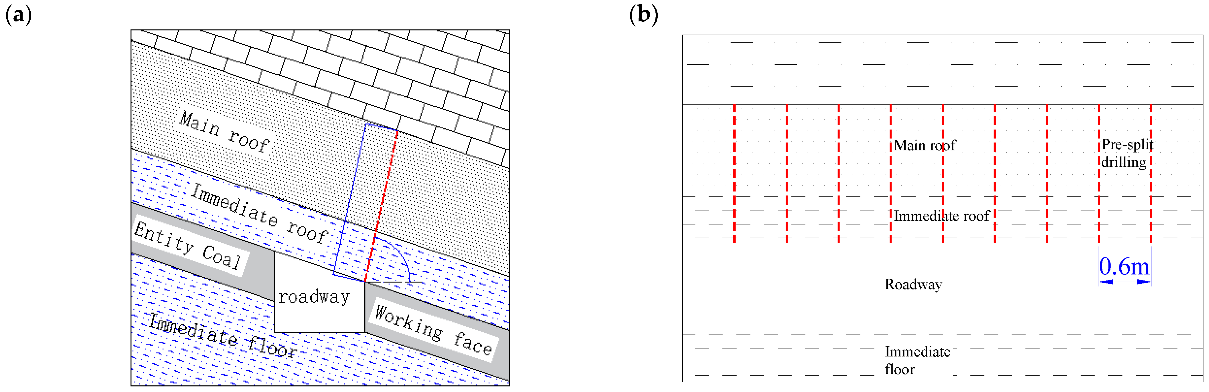
Roadway excavation stage: The additional stress caused by excavation disturbance is relatively small, and the direct roof is supported by solid coal at both ends, with limited expansion of internal cracks. It remains stable under the support of the solid coal at both ends. In this stage, the immediate roof can be simplified as a beam structure with both ends fixed, as shown in Figure 5a.
(2)
Pre-splitting roof cutting stage: In this stage, the advanced working face implements pre-splitting cutting on the roadway roof, severing the mechanical connection between the roadway roof and the working face roof. The pre-splitting roof cutting holes are generally at an angle of 70~80° with the roadway roof [23,24]. Under the action of the self-weight of the overlying strata and the mining support pressure, the roadway roof at both ends remains supported by solid coal after the advanced working face pre-splitting roof cutting. This stage generally focuses on controlling the stability of the roof and increasing temporary support within the roadway. Temporary support often uses single-leg supports and stacking supports, which can simplify the roadway roof structure into a cantilever beam with one end fixed and the other end simply supported, as shown in Figure 5b.
(3)
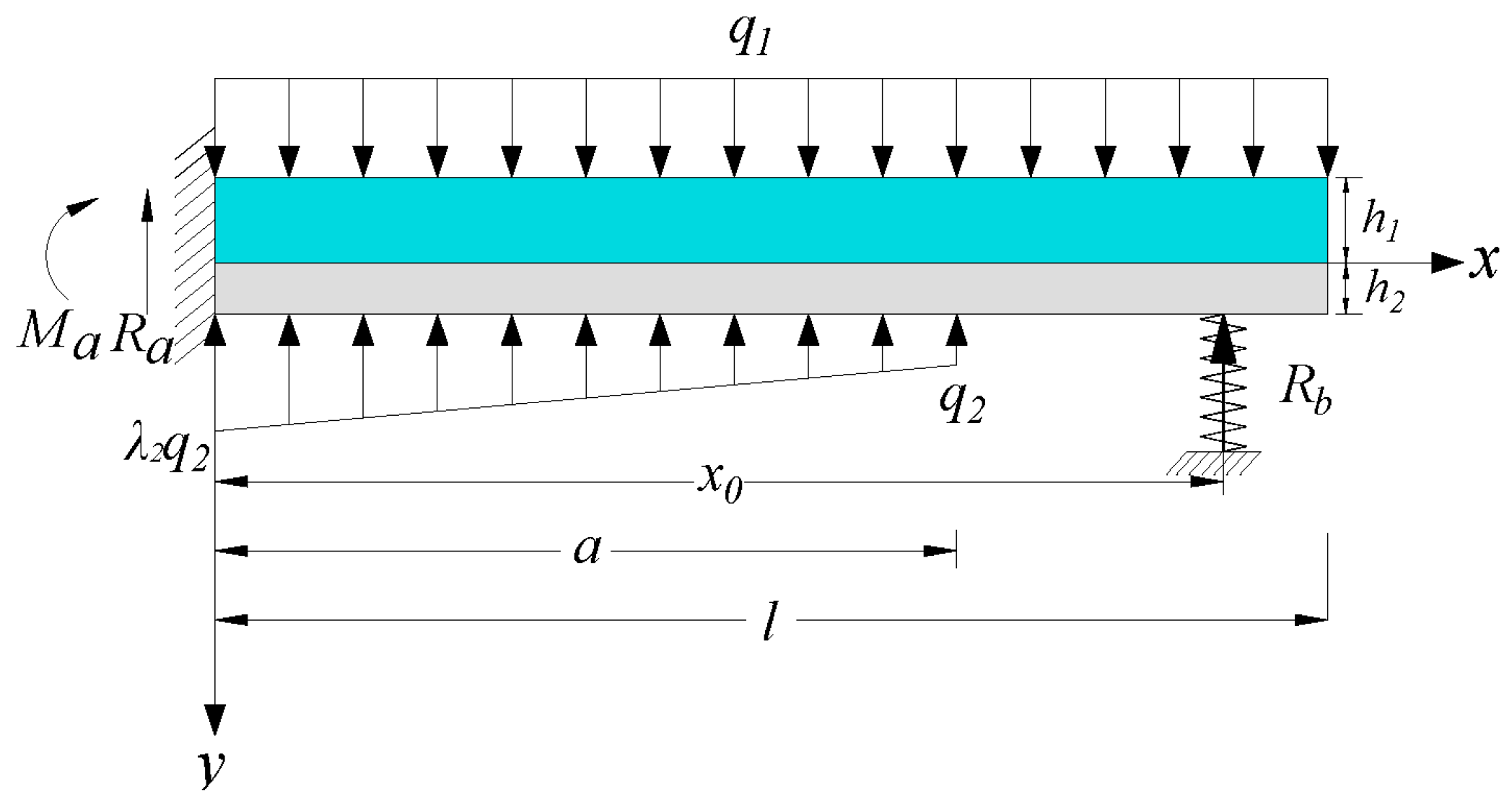
Primary mining retention stage: Due to the influence of the working face mining support stress and the large turning subsidence space of the roadway roof, the movement of the roadway roof is intense and prone to significant deformation, which is a critical support stage during the retention process. To control the subsidence of the roadway roof, temporary support is usually increased within the roadway. This often involves the use of multiple rows of single-leg supports or two rows of stacking supports. Therefore, the roadway roof structure in this stage can be simplified as a cantilever beam with one end fixed (solid coal), as shown in Figure 5c.
(4)
Retaining stability stage and secondary mining advanced impact stage: After the roadway is stabilized, the caved gangue fills the gob area, providing support for the roadway roof on the cutting side until the secondary reuse of the roadway ends. Therefore, during the retaining stability and the secondary mining advanced impact stage, the retaining roadway roof can be simplified as a beam structure with one end fixed and the other end simply supported, as shown in Figure 5d.
Figure 5. Evolution of direct roof structure in gob-side entry retaining by roof cutting: (a) Excavation stage. (b) Advanced cutting stage. (c) Primary mining retention stage. (d) Retaining stability.
Applsci 14 06520 g005

2.3. Roadway Roof Deformation Law of GERRC

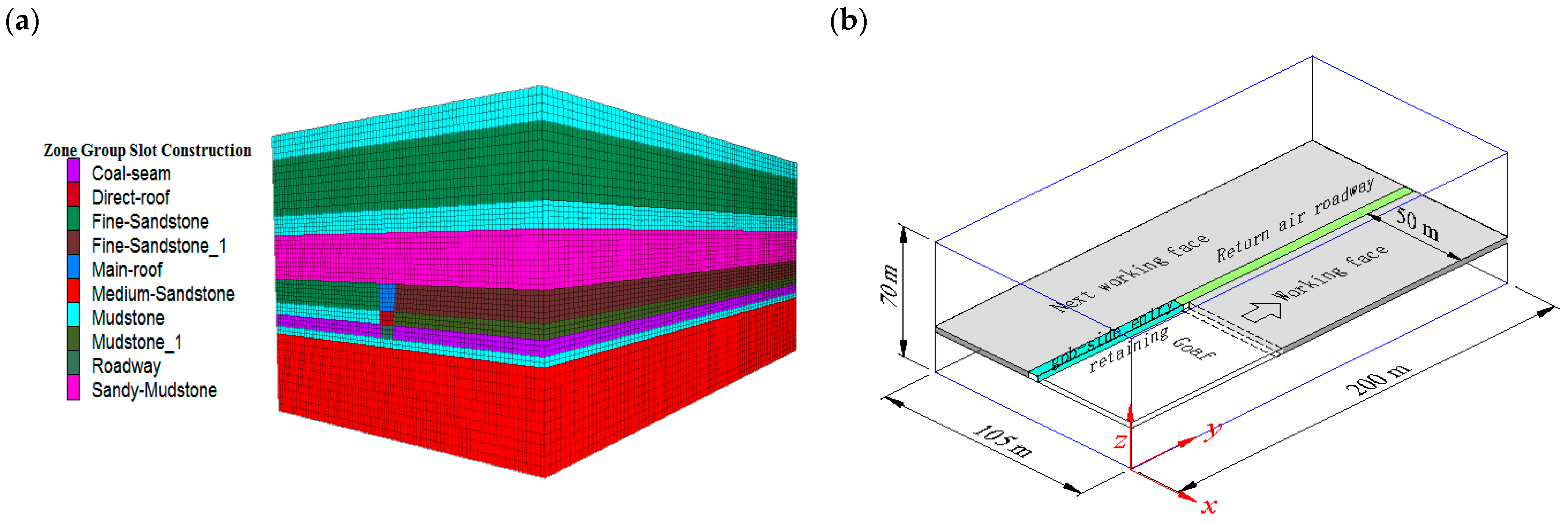
2.3.1. Model Establishment

Based on the coal seam and roof and floor rock strata conditions at the 7135 working face of Qidong Coal Mine, a numerical calculation model was established. The model dimensions are as follows: length 200 m, width 105 m, and height 70 m, as shown in Figure 6a. The coal seam’s mining thickness is 3.3 m, with a full height extraction at one time. The roof rock strata thickness is 44.7 m, and the floor rock layer thickness is 22 m. The coal seam dip angle is calculated as nearly horizontal. The mining width of the working face is 100 m. To save computational resources, the model is built with a mining operation that takes half of the mining width (50 m) for calculations. During mining, GERRC is implemented in the return airway. The cross-sectional dimensions of the return airway are as follows: width × height = 5 m × 3.3 m, as shown in Figure 6b.
The numerical calculation was carried out using FLAC 3D6.0 software, and the Mohr–Coulomb constitutive model was used for numerical analysis. In the numerical model, solid elements were used for each rock layer, and the physical and mechanical parameters of each rock layer and support structure are shown in Table 1. During the simulated excavation of the working face, the goaf was treated using an unfilled method afterwards. The interface structural element is used to represent the cutting seam surface in the analysis. By assigning normal stiffness and shear stiffness parameters to the structural element, the contact effect after cutting is obtained, as shown in Table 2.

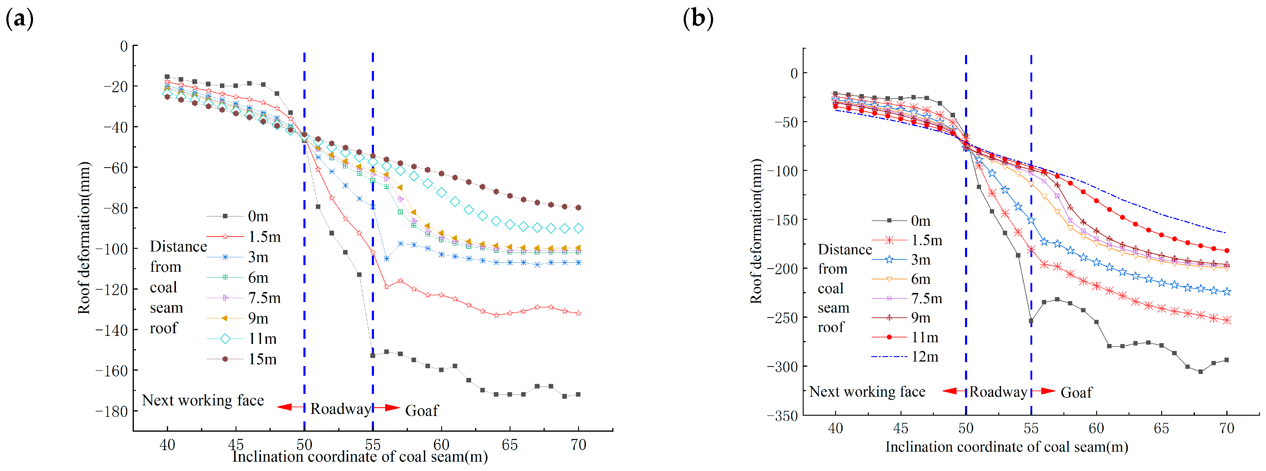
2.3.2. Roadway Roof Deformation Laws during Roadway Retaining

The working face was advanced circularly to 120 m with 20 m in one advancement (3000 steps). To obtain the roof deformation characteristics during the retaining period, displacement measuring lines are arranged at the middle of the roadway, 10 m behind, and 60 m behind, referred to as Line I, Line II, and Line III, respectively, as shown in Figure 7. The monitoring lines located 1.5 m and 3 m away from the roadway roof, respectively, monitor the deformation of the immediate roof and main roof.
The roof subsidence curves at different depths of the roadway along the strike are obtained from monitoring Line I, as shown in Figure 8, with the horizontal axis representing the distance from the working face, where the origin (0) is the location of the working face. It can be observed that
① The deformation law of the roadway roof tends to be consistent between the advanced working face and the lagging working face. At 50 m behind the working face, the subsidence of the middle of the roadway roof tends to be stable with the maximum deformation of 154 mm. ② There is a significant difference in the roof subsidence at different depths in the gob-side roadway. The overall subsidence pattern shows that the subsidence of the shallow roof is greater than that of the deep roof. The subsidence of the central part of the immediate roof shows a clear decreasing trend. When the stratum reaches the main roof, the subsidence significantly decreases. As the roof depth increases, the subsidence no longer decreases significantly. In the advanced mining impact stage, the displacement of the lower surface of the immediate roof gradually decreases, with a maximum value of 70 mm and a minimum value of 40 mm. ③ As the depth of the roadway roof increases, the deformation of the roof rock decreases. The deformation of the rock formation 1.5 m from the roof and the rock formation 3 m from the roof direction is consistent, indicating that the immediate roof and main roof have a consistent deformation law. ④ The deformation of the main roof determines the deformation of the immediate roof.
Figure 8. Deformation laws of roadway roofs.
Applsci 14 06520 g008
Measurement lines Ⅱ and Ⅲ recorded the deformation law of roadway roof 10 m and 60 m behind the working face, respectively, as shown in Figure 9a,b.
As shown in Figure 9, inclined roadway roofs subside to the mined-out side. With the increase in the depth, the degree and rate of deformation decrease. The main roof of the mined-out area and its lower rock layer fracture and sink along the cutting line. The deformation trend of the upper rock layer above the final drill hole is the same, and the pre-blasting roof cutting has less influence on the deformation of the rock layer above the cutting line. (1) The deformation of the roadway roof is greater with the distance from the coal side to the mined-out side closer. The maximum deformation of the immediate roof is 250 mm at the roof side, and the maximum deformation of the main roof is 150 mm at 60 m behind the working face. (2) Within the inclination range of the roadway, the immediate roof (1.5 m from the coal seam roof) and the main roof (3 m from the coal seam roof) subside with the same deformation law.

3. Roof Movement Mechanical Model of GERRC

3.1. Mathematic Expression of Shear Stress

According to the analysis in Section 2.2 and Section 2.3, it can be concluded that the main roof subsidence deformation of GERRC determines the subsidence deformation of the immediate roof. Thus, the immediate roof and main roof mechanics model are established according to the literature [25,26], as shown in Figure 10 for convenient calculation, and the following assumptions are made:
① The immediate roof and the main roof are elastic deformers.
② The internal friction angle φ0 and the cohesive force c0 between the immediate roof and the main roof during roadway retaining are constant values.
Figure 10. Mechanical model of immediate roof and main roof.
Applsci 14 06520 g010
According to the reference [25], if λ1 = 1, q3 = 0, then Rb is
R b = q 1 q 2 15 a 3 x 0 a 4 + q 1 λ 2 q 2 5 a 3 x 0 a 4 + 5 q 1 x 0 4 4 l x 0 3 + 6 l 2 x 0 2 4 a 3 x 0 + a 4 120 E I k + 40 x 0 3
The bending moment of the immediate roof and the main roof can be expressed as
M x = R b x 0 x q 1 2 l x 2 , a x x 0 q 1 2 l x 2 , x 0 < x l
The deformation amount during the entire process of obtaining the roadway roof is
y x = 5 q 1 a 3 4 x a + 5 q 1 x 4 4 l x 3 + 6 l 2 x 2 4 a 3 x + a 4 120 E I + 20 k x 0 2 3 x x 0 , x 0 x 5 q 1 a 3 4 x a + 5 q 1 x 4 4 l x 3 + 6 l 2 x 2 4 a 3 x + a 4 120 E I + 20 k x 2 3 x 0 x , a x x 0
where y x —deflection at position x in the roadway; q 1 —superimposed stress on the roadway roof, MPa; a —length from the left side of the roadway to the limit equilibrium position, m; l—length from the right side of the roadway to the limit equilibrium position, m; E —elastic modulus of the roadway roof, GPa; I —moment of inertia of the roadway roof (immediate and main roof), related to the thickness h of the roof, m4; k —support stiffness of the temporary support (coal seam), N/m; x 0 —position of the temporary support (stack-type support), m.

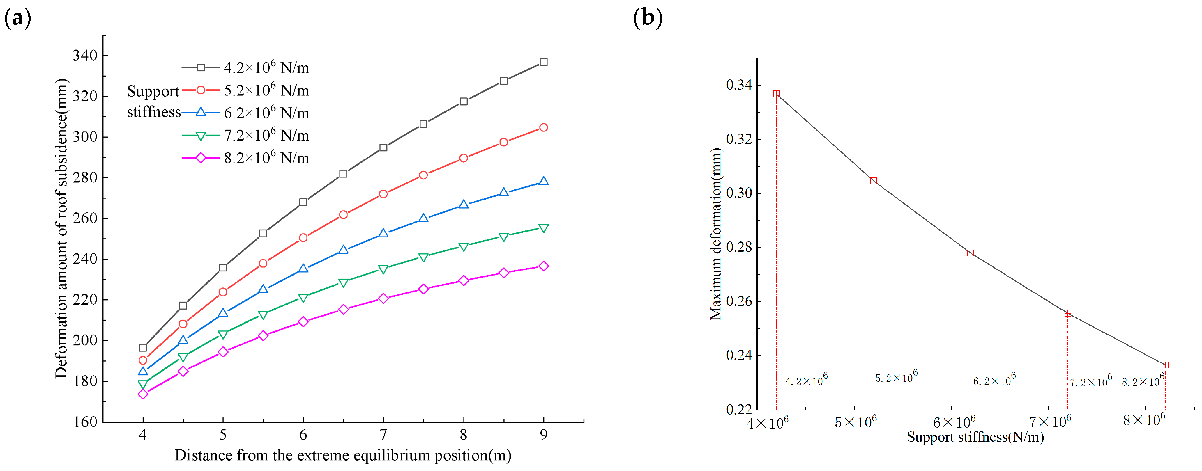
3.2. Relationship between Roadway Roof Deformation and Support Stiffness

Based on engineering test conditions, the roadway roof load during mining retention is approximately q1 = 2.2 MPa, q = 4.1 MPa, and other measured parameters are E = 2.5 GPa, γ = 250 kN/m3, h = 3 m, a = 4.0 m, λ = 2.0, x0 = 8.3 m (roadway width 4.3 m), k = 6.62 × 10⁶ N/m.
From Equation (3), it is known that during mining retention, the location and stiffness of temporary support (stacking support) within the roadway are crucial for roof control. When the additional stiffness of the temporary support is 6.2 × 10⁶ N/m, the roof subsidence increases towards the gob side, generally in a parabolic form, with the subsidence increasing as it moves closer to the cutting side. The closer the support position is to the cutting side, the smaller the roof subsidence. In line with the test roadway, the limit equilibrium zone is 4 m away from the roadway wall. When the support position is at 6.3 m, the roof subsidence on the solid coal side is 100 mm, and the roof subsidence at the cutting side increases to 345 mm, an increase of 70.1%, indicating that during roadway retention, the roadway roof will rotate and subside towards the gob side. During roadway retention along the roadway roof dip direction, as the support position moves from the solid coal to the cutting side of the roadway wall, the deformation of the roof at different positions shows a decreasing trend, as shown in Figure 11a. By statistically analyzing the maximum deformation of the roadway roof at different support positions, as shown in Figure 11b, the maximum deformation occurs when the support position is at the solid coal roadway wall side. As the support position moves closer to the solid coal side, the maximum deformation decreases. Therefore, in engineering practice, it is recommended to place temporary support bodies close to the cutting side of the roof to control roof subsidence deformation.
As the support stiffness increases from 4.2 × 10⁶ N/m to 8.2 × 10⁶ N/m, the roadway roof subsidence gradually decreases. The deformation of the roof near the cutting side becomes larger. When the support stiffness is 4.2 × 10⁶ N/m, the maximum roof subsidence is 338 mm. When the support stiffness increases to 8.2 × 10⁶ N/m, the maximum roof subsidence decreases to 235 mm, a reduction of 30.5%, as shown in Figure 12. In engineering practice, the stiffness of the support system is the ability of the support system to resist deformation under force. The roof deformation of GERRC is loaded onto the support body, and the deformation of the immediate floor is also loaded onto the support system. An increase in the number of temporary support bodies can be used to increase the stiffness of the support system and control the subsidence and deformation of the roof. Similarly, it can also suppress the deformation of the floor drum.
From the above analysis, it is clear that increasing the stiffness of the temporary reinforcement support for the roadway roof during retention can reduce the roof deformation. Additionally, the closer the support position is to the cutting side of the roadway wall, the more it can control the roof deformation. During GERRC, using a single high-stiffness support body can control roof deformation, but it also causes the support body and the roof to accumulate elastic energy, which may lead to impact accidents during the retreat. Therefore, to control roof subsidence, it is necessary to fully utilize the matching of the support stiffness and roof subsidence. In the dip direction of the roadway roof, parallel support can be adopted, increasing the number of support bodies to enhance the stiffness of the support system, and the support position should be as close as possible to the cutting side of the roadway wall.

4. Roof Control Effect during Retention Stage

4.1. Roof Support Parameters during Primary Mining Retention Stage

Based on the analysis of the roof deformation mechanism in GERRC, it is known that roof deformation is related not only to the self-bearing strength of the roof but also to the support stiffness. Cables are commonly used as reinforcing elements in support systems, which are subject to dynamic loads in burst-prone excavations [27]. During the roof cutting and roadway retention period, as the roof of the goaf collapses, the mining stress would disturb the roadway support body. Due to the high strain rate and ability to absorb the elastic potential energy of the cables, it was necessary to monitor the stress on the anchor cable during the roadway retention period. To improve the self-bearing strength of the roof during retention and to fully utilize the matching of the support stiffness and roof deformation, the return airway of the 7135 working face adopted a combined support of bolts (cables), and stacking supports during the retaining period in GERRC. In the dip direction of the roadway roof during retention, temporary reinforcement support was provided using double-row stacking supports, with a spacing of 1.2 m, a row spacing of 2 m, and continuous layout along the strike. The section support of the roadway during GERRC is shown in Figure 13a, and the roof support is shown in Figure 13b. To facilitate the display of the support parameters, the different support masses in Figure 13a are numbered to form a statistical table of the support parameters, as shown in Table 3.

4.2. Roof Control Effect during Primary Mining Retention Stage

During the mining period of the 7135 working face, the measured resistance of the stacking supports and the roadway roof formation effect during retention reflect the control effectiveness.
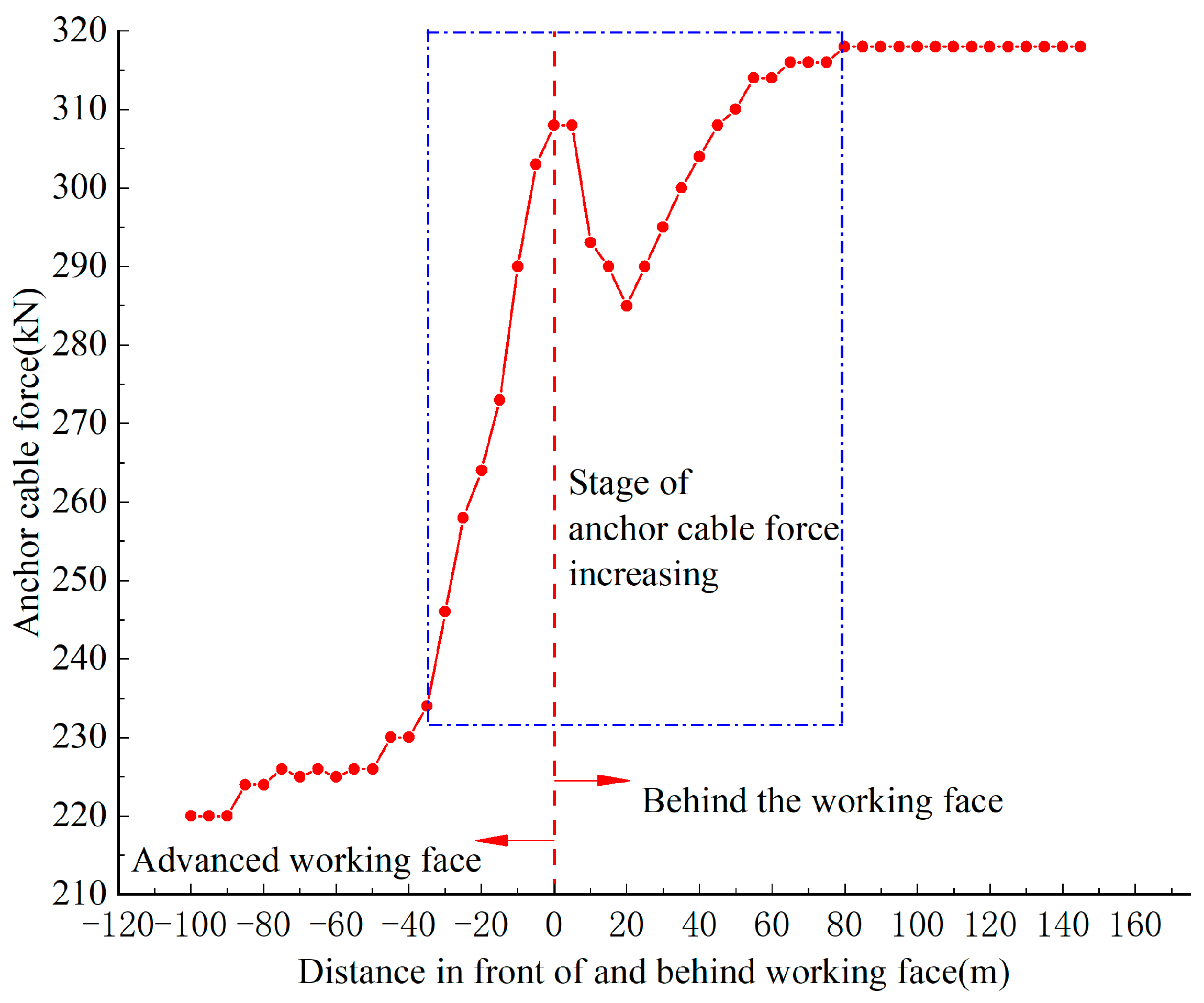
Stress analysis of reinforcing anchor cables
During the movement of the gob-side roadway roof, the stress of the reinforcing anchor cables can reflect the roof collapse process and state. As shown in Figure 14, the resistance-increasing section of the reinforcing anchor cables occurs from 40 m ahead of the working face to 60 m behind the working face. Affected by the pre-splitting blasting and advanced mining, the resistance-increasing rate of the anchor cables ahead of the working face is significantly higher than that of the anchor cables behind the working face. The tension of the anchor cables increases from 230 kN to 304 kN. During this stage, the roadway roof undergoes pre-splitting blasting, fracture movement, and subsequent consolidation.
Behind the working face, due to the roadway roof experiencing pressure relief, fracture, subsidence, and gradual compaction, the tension of the anchor cables first decreases and then increases until it stabilizes. After 90 m behind the working face, the tension of the anchor cables stabilizes at 316 kN, indicating that the roof on the gob side has fully collapsed and compacted along the pre-splitting surface. Due to the sinking and then stabilizing trend of the roof during the cutting to retaining period, the tension value of the anchor cables after the retaining period is significantly higher than that of the anchor cables at the stable stage ahead of the working face.
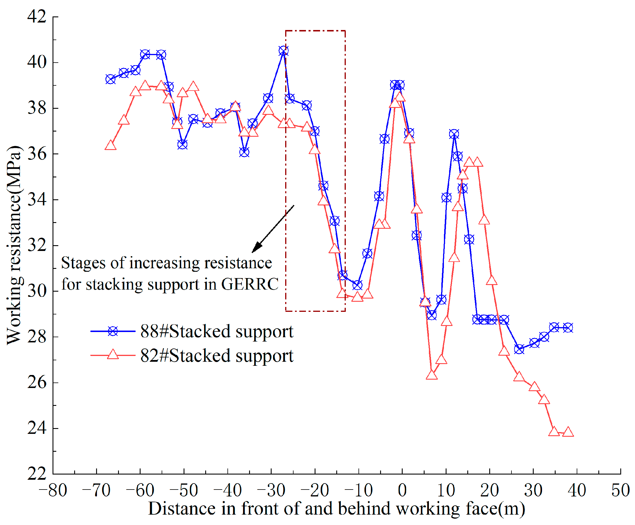
Analysis of stack-type support resistance
During the mining period of the working face, the ZQ4000/20.6/45-type advanced support hydraulic support for the roadway, namely the stacking support, was used to temporarily reinforce and support the roof of the retained roadway. The rated working resistance of the stacking support was 41.6 MPa. The measured variation in the working resistance of the stacking support is shown in Figure 15. During the mining period, the measured resistance of the stacking supports changes, as shown in Figure 15.
The resistance of the stacking supports increases from 35 m ahead of the working face to 70 m behind the working face. Between 25 m ahead of the working face and 15 m behind the working face, the supports are affected by the periodic pressure from the working face, and the resistance changes significantly. The 15 m to 30 m range behind the working face is the stage of increased resistance for the stack-type supports. As the retention distance increases, the support resistance fluctuates, generally stabilizing, with a maximum working resistance of 40 MPa, which falls within the reasonable range of resistance changes for the supports.
Observing the roadway roof control effect, as shown in Figure 16, the roof formation is complete during the retaining period, without large deformations or structural instability. The roadway formation effect is good, meeting the requirements of ventilation, pedestrian traffic, and safe mining.

5. Main Conclusions

(1) Taking the Qidong Coal Mine 7135 working face as the engineering background, the direction and tendency deformation law in different layers during roadway retaining were studied via numerical simulation. The maximum deformation of the immediate roof and main roof are 250 mm and 150 mm, respectively, indicating that the immediate roof and main roof can deform coordinately during roadway retaining. The shear damage of the bolt rod within the effective support area as the critical index was used to obtain the dislocation criterion between the immediate roof and the main roof to analyze the quantitative relationship among the temporary support stiffness, bolt preload, and bolt support spacing between rows.
(2) The relationship between the temporary support of the roof, bolt preload, and bolt support spacing between rows degree during roadway retaining were obtained. In engineering practice, it is proposed to improve the stability of the roadway roof and control of roof subsidence by increasing the number of temporary supports in the roadway, improving the support stiffness, reducing the bolt support spacing between rows, and improving the bolt preload.
(3) The deformation patterns of the roadway along the strike and dip during gob-side entry retaining by roof cutting are obtained. Based on the quantitative relationship between the roof subsidence and support stiffness, it is determined that during retention, the temporary reinforcement support within the roadway adopts double-row stack-type supports. Combining the roof control effect during the retaining period of GERRC, the rationality of the support has been verified. The secondary use of the gob-side entry retaining by roof cutting needs to be carried out after the stability of the roof movement. When the coal seam behind the long wall front is excavated, the lag distance should not be less than 90 m.

Author Contributions

Conceptualization, X.L. and X.H.; methodology, Y.L.; software, C.L.; validation, X.L. and C.L.; formal analysis, X.L.; investigation, C.L.; resources, X.H.; data curation, X.L.; writing—original draft preparation, X.L.; writing—review and editing, X.L.; visualization, C.L. All authors have read and agreed to the published version of the manuscript.

Funding

This study was financed from the National Natural Science Foundation of China (52374075, U23A20601).

Institutional Review Board Statement

The study was not involving humans or animals, and the study do not require ethical approval. We choose to exclude this statement.

Informed Consent Statement

We choose to exclude this statement, because the study did not involve humans.

Data Availability Statement

The data used to support the findings of this study are available from the corresponding author upon request.

Acknowledgments

The authors express sincere thanks to the journal editors and anonymous reviewers for their help and beneficial comments on the manuscript.

Conflicts of Interest

The authors declare that there are no conflicts of interest.

References

  1. Zhang, Z.Z.; Bai, J.B.; Wang, X.G.; Xu, Y.; Yan, S.; Liu, H.L.; Wu, W.; Zhang, W.G. Review and development of surrounding rock controltechnology for gob-side entry retaining in China. J. China Coal Soc. 2023, 48, 3979–4000. [Google Scholar]
  2. He, M.C.; Chen, S.Y.; Guo, Z.B.; Yang, J.; Gao, Y.B. Control of surrounding rock structure for gob side entry retaining by cutting roof to release pressure and its engineering application. Technol. J. China Univ. Min. 2017, 46, 959–969. [Google Scholar]
  3. He, M.; Gao, Y.; Gai, Q. Mechanical principle and mining methods of automagical entry formation without coal pillars. Coal Sci. Technol. 2023, 51, 19–30. [Google Scholar]
  4. He, M. Theory and engineering practice for non-pillars mining withautomagical entry formation and 110 mining method. J. Min. Saf. Eng. 2023, 40, 869–881. [Google Scholar]
  5. Gao, Y.B.; Guo, Z.B.; Yang, J.; Wang, J.W.; Wang, Y.J. Steady analysis of gob-side entry retaining formed by roof fracturing and control techniques by optimizing mine pressure. J. China Coal Soc. 2017, 42, 1672–1681. [Google Scholar]
  6. Gao, Y.; Wang, Q.; Yang, J.; Ding, W.; Fu, Q.; Xu, X. Mechanism of deformation and pressure relief control of dynamic gob-side entry surroundings in fully-mechanized caving mining for extra-thick coal seam. Coal Sci. Technol. 2023, 51, 83–94. [Google Scholar]
  7. Yang, J.; Fu, Q.; Gao, Y.; Cheng, Y.; Zhang, J. Research on roof deformation laws and mechanism in a non-pillar mining method with entry automatically formed during the whole cycle. J. China Coal Soc. 2020, 45, 87–98. [Google Scholar]
  8. Wei, Q.-L.; Wang, Y.-J.; Yang, J.; Gao, Y.-B.; Hou, S.-L.; Qiao, B.-W. Roof deformation mechanism and control measures of pillarless mining withgob-side entry retaining by roof cutting and pressure relief. Rock Soil Mech. 2020, 41, 989–998. [Google Scholar]
  9. Chen, S.Y.; He, M.C.; Guo, Z.B.; Yang, H.; Yang, J. Control Countermeasures of Surrounding Rock in Deep Gob-side Entry Retaining by Cutting Roof. Adv. Eng. Sci. 2019, 51, 107–116. [Google Scholar]
  10. Chen, S.Y.; He, M.C.; Wang, H.J.; Yuan, G.X.; Zhao, F.; Guo, Z.B. Coordination control and stress evolution of surrounding rock of gob-side entry retaining cutting roof in deep mine. J. Min. Saf. Eng. 2019, 36, 660–669. [Google Scholar]
  11. Guo, Z.; Zhao, Y.; Yang, D.; Gao, J.; Yin, S.; Kuai, X. Study on roof deformation mechanism and control technology of cross-fault roof cutting and pressure relief self-forming roadway. Coal Sci. Technol. 2024, 52, 14–28. [Google Scholar]
  12. Liu, X.; Hua, X.; Yang, P.; Yang, S.; Ma, Y. A quantitative study on roof dislocation criterion and support parameters of entry retaining by roof cutting in deep mine. J. Min. Saf. Eng. 2021, 38, 1122–1133. [Google Scholar]
  13. Chen, L.; Kang, H.; Jang, P.; Li, W.; Yang, J.; Zhen, Y. Deformation and failure characteristics and control technology of surrounding rocks in deeply gob-side entry driving. J. Min. Saf. Eng. 2021, 38, 227–236. [Google Scholar]
  14. He, M.; Wu, Y.; Gao, Y.; Tao, Z. Research progress of rock mechanics in deep mining. J. China Coal Soc. 2024, 49, 75–99. [Google Scholar]
  15. Xie, H.; Zhang, R.; Zhang, Z.; Gao, M.; Li, C.; He, Z.; Liu, T. Reflections and explorations on deep earth science and deep earth engineering technology. J. China Coal Soc. 2023, 48, 3959–3978. [Google Scholar]
  16. Skrzypkowski, K. Comparative Analysis of the Mining Cribs Models Filled with Gangue. Energies 2020, 13, 5290. [Google Scholar] [CrossRef]
  17. Shan, Z.; Porter, I.; Nemcik, J.; Baafi, E. Investigating the behaviour of fibre reinforced polymers and steel mesh when supporting coal mine roof strata subject to buckling. Rock Mech. Rock Eng. 2019, 52, 1857–1869. [Google Scholar] [CrossRef]
  18. Sinha, S.; Chugh, Y.P. An evaluation of roof support plans at two coal mines in Illinois using numerical models. Int. J. Rock Mech. Min. Sci. 2016, 82, 1–9. [Google Scholar] [CrossRef]
  19. Zuo, J.P.; Wen, J.H.; Hu, S.Y.; Zhao, S.K. Theoretical model and simulation study of uniform strength beam support in deep coal mine roadway. J. China Coal Soc. 2018, 43, 1–11. [Google Scholar]
  20. Gao, Y.B.; Yang, J.; Zhang, X.Y.; Xue, H.J.; He, M.C. Study on Surrounding Rock Control of Roadways in Deep Coal Mines Based on Roof Cutting and Pressure Release Technology by Directional Tensile Blasting. Chin. J. Rock Mech. Eng. 2019, 38, 2045–2056. [Google Scholar]
  21. Zhao, Y.; Zhang, N.; Zhen, X.; Baoyu, L. Structural optimization of overlying strata for gob-side entry retaining in 1000 m deep mine with direct thick and hard roof. J. Min. Saf. Eng. 2015, 32, 714–720. [Google Scholar]
  22. Wang, Q.; Zhang, P.; Jiang, Z.H.; He, M.; Li, S.; Wang, Y.; Jiang, B. Automatic roadway formation method by roof cutting with high strength bolt-grouting in deep coal mine and its validation. J. China Coal Soc. 2021, 46, 382–397. [Google Scholar]
  23. Chen, S.Y.; Zhao, B.; Yuan, Y.; He, M.C.; Guo, Z.B.; Zhao, F. Engineering experiment on gob-side entry retaining byroof cutting of deep mining face in Cheng jiao coalmine. J. Min. Saf. Eng. 2021, 38, 121–129. [Google Scholar]
  24. Hu, C.; Wang, J.; He, M.; Wang, X.; Wang, J.; Zhang, Z. Study on key parameters of self-formed roadway without coal pillar by roof cutting and pressure relief in medium and thick coal seam. Coal Sci. Technol. 2022, 50, 117–123. [Google Scholar]
  25. Liu, X.; Hua, X.; Yang, P.; Huang, Y. A study of the mechanical structure of the immediate roof during the whole process of non-pillar gob-side entry retaining by roof cutting. Energy Explor. Exploit. 2020, 38, 1706–1724. [Google Scholar] [CrossRef]
  26. Hua, X.Z.; Liu, X.; Huang, Z.G.; Yang, P.; Ma, Y. Stability mechanism of non-pillar gob-side entry retaining by roof cutting under the coupled static-dynamic loading. J. China Coal Soc. 2020, 45, 3696–3708. [Google Scholar]
  27. Tahmasebinia, F.; Yang, A.; Feghali, P.; Skrzypkowski, K. A Numerical Investigation to Calculate Ultimate Limit State Capacity of Cable Bolts Subjected to Impact Loading. Appl. Sci. 2023, 13, 15. [Google Scholar] [CrossRef]
Figure 1. The schematic diagram of GERRC.
Applsci 14 06520 g001
Figure 2. Roadway layout and geologic histogram of working face: (a) Geologic histogram. (b) Roadway layout plan.
Applsci 14 06520 g002
Figure 3. Design parameters of pre-splitting drilling in roof cutting roadway: (a) Plan view of roof cutting parameters. (b) Profile view of roof cutting parameters.
Applsci 14 06520 g003
Figure 4. Stages of gob-side entry retaining by roof cutting.
Applsci 14 06520 g004
Figure 6. Calculation model and measuring line layout of gob-side entry retaining by roof cutting (GERRC): (a) Numerical model. (b) Three-dimensional model geometric dimensions.
Applsci 14 06520 g006
Figure 7. Displacement measuring line layout.
Applsci 14 06520 g007
Figure 9. Roof displacement and stress distribution of roadway roof 10 m behind the working face: (a) 60 m behind the working face, (b) 10 m behind the working face.
Applsci 14 06520 g009
Figure 11. Influence of support position on roof subsidence: (a) Roadway roof deformation at different support positions. (b) Maximum roadway deformation at different support positions.
Applsci 14 06520 g011
Figure 12. Influence of support stiffness on roof subsidence: (a) The deformation of the dip roof of roadway with different support stiffness. (b) Maximum roadway roof deformation at different support stiffness.
Applsci 14 06520 g012
Figure 13. Roof support parameters during primary mining retention Stage: (a) Cross-section diagram of roof support behind working face. (b) Plan of roof support behind working face.
Applsci 14 06520 g013
Figure 14. Stress curve of anchor cable.
Applsci 14 06520 g014
Figure 15. Variation curve of working resistance of stack-type support.
Applsci 14 06520 g015
Figure 16. Support effect of stacking support during retaining roadway. (a) Supporting effect of stacking support 10 m behind the working face. (b) Supporting effect of stacked support 60 m behind the working face.
Applsci 14 06520 g016
Table 1. Thickness of each rock strata in numerical model.
Rock Strata NameLayer Thickness
/m
Density
kN/m3
Bulk Modulus
GPa
Shear Modulus
GPa
Internal Friction Angle (°) Cohesion
MPa
Tensile Strength
MPa
Mudstone 7242.881.53261.171.3
Fine sandstone142610.357.74363.154.2
Mudstone 5242.881.53261.171.3
Sandy mudstone11253.61.89291.352.1
Fine sandstone62610.357.74363.154.2
Sandy mudstone1.7253.61.89291.352.1
Coal seam3.3141.350.63230.720.14
Mudstone 2242.881.53261.171.3
Medium sandstone20269.386.54343.133.4
Table 2. Physical and mechanical index of structural plane element.
Structural NameShear Stiffness
N/m
Normal Stiffness
N/m
Poisson RatioInternal Friction Angle
Structural surface1 × 1082 × 1060.2515
Table 3. Roof support parameters of 7135 return air roadway in Qidong Coal Mine.
Support Position1. Strengthening Cable Bolts2. Cable Bolts Support Parameters3. Bolting Parameter4. Stacking Support
Support SpecificationsSpacing between RowsSupport SpecificationsSpacing between RowsSupport SpecificationsSpacing between RowsSupport Parameters
Behind the working face in GERRCSteel strand, Φ21.6 mm × 12.3 mSingle row, 800 mmSteel strand, Φ21.6 mm × 10.3 mMake a step layout of the working face, 1.5 × 1.6 mScrew thread steel, Φ20 mm × 2.4 m0.8 × 0.8 mDouble row
Disclaimer/Publisher’s Note: The statements, opinions and data contained in all publications are solely those of the individual author(s) and contributor(s) and not of MDPI and/or the editor(s). MDPI and/or the editor(s) disclaim responsibility for any injury to people or property resulting from any ideas, methods, instructions or products referred to in the content.

