Highlights
What was the main work done?
- A study was conducted to investigate the stratification performance of storage tanks equipped with porous obstacles.
- Five CFD models of storage tanks with different internal structures were established.
- Comparing the thermal stratification performance of storage tanks with different internal structures.
- The stratification characteristics of traditional storage tanks, perforated plate obstacle tanks, and porous obstacle tanks were compared. Additionally, the heat storage properties of tanks with porous obstacles installed in various configurations were evaluated.
What are the main findings?
- The installation of porous obstacles within storage tanks yields superior stratification effects compared to perforated plate obstacles. Storage tanks equipped with porous obstacles near both the top and bottom exhibit optimal thermal stratification performance.
Abstract
Thermocline storage tanks are critical components in energy storage systems for solar renewable energy utilization. The use of thermal stratification of the working fluid within the storage tank for energy storage is a pivotal technology in these systems. Effective thermal stratification can significantly enhance energy storage efficiency, meet a broader range of user demands, and improve the overall performance of the storage tank. Therefore, enhancing the energy storage efficiency of storage tanks is an essential objective. To promote internal temperature stratification within the tank, this study introduces a porous obstacle designed to improve the tank’s internal structure. A comparative analysis was conducted with tanks featuring different structural configurations. Using the commercial finite element software ANSYS, an unsteady Computational Fluid Dynamics (CFD) model was formulated to simulate the energy discharge process of five different tank structures under various operating conditions. By analyzing the internal temperature distribution, thermocline thickness, dimensionless exergy efficiency, and flow field trajectories, the stratification characteristics were determined. The results indicate that the porous obstacle significantly enhances stratification compared to the perforated plate obstacle. At a flow rate of 0.3 m/s, the thermocline thickness in traditional tanks and tanks with perforated plate obstacles is 42% and 14.3% greater, respectively, than in tanks with porous obstacles. Additionally, the study demonstrates that temperature stratification is more pronounced when the porous obstacle is positioned closer to the tank’s bottom, with the optimal configuration being the placement of porous obstacles near both the top and bottom of the tank. At a flow rate of 0.3 m/s, the thermocline thickness in tanks with porous obstacles only at the bottom and middle is 17% and 133% greater, respectively, than in tanks with porous obstacles at both the top and bottom.
1. Introduction
With economic development, the demand for energy in human society is increasing, placing significant pressure on the environment. In response, attention has turned to renewable energy sources. Among these, solar energy is the most widely utilized, and tank energy storage is a crucial method for harnessing solar energy. Tank energy storage can be categorized into two forms: dual-tank storage, where hot and cold working fluids are stored separately, and single-tank storage, where hot and cold working fluids coexist. Due to its lower manufacturing costs and environmental benefits, single-tank energy storage is more widely applied [1]. This type of tank, also known as a thermocline storage tank, separates the hot and cold working fluids using a thermocline. Under the influence of gravity, the hot working fluid is positioned at the top, while the cold working fluid remains at the bottom [2,3]. Thermal stratification within storage tanks has consistently been a focal point of research in the relevant field, as enhancing thermal stratification can improve both the charging and discharging efficiency of the system [4].
The thickness of the thermocline is a key factor affecting the efficiency of energy storage in a single tank. For a given volume, a thicker thermocline indicates more severe fluid mixing, resulting in lower energy storage efficiency [5]. To improve energy storage efficiency, numerous researchers have investigated the temperature stratification within storage tanks. Dogan Erdemir et al. designed four different shapes of obstacles within the storage tank. Through experimental analysis, they concluded that Type a obstacles improved stratification more effectively. They also noted that the position of the obstacles influences the stratification effect [6]. Long Gao et al. studied the energy storage effects of obstacles with central openings. By comparing numerical simulations with experimental results, they determined the optimal hole diameter, installation position, and flow rate for the best stratification effect [7]. Dogan Erdemir et al. investigated the impact of different baffle configurations on energy storage in horizontal solar water tanks. Through experimental results analysis, they identified the baffle combination that achieved the best stratification effect [8]. Necdet Altuntop et al. studied the stratification characteristics of 12 different shapes of obstacles in storage tanks. Through numerical calculations and experiments, they concluded that obstacles with central perforations exhibited the best stratification performance [9]. Zhengyu Yin et al. designed a special type of baffle that can automatically float up and down. The edges of the baffle contact the tank wall, preventing convection between cold and hot water, thereby making stratification influenced only by thermal conduction. The results showed that this device can improve stratification, and baffles with lower thermal conductivity result in a thinner thermocline [10]. Huimin Feng et al. studied the installation of different numbers of perforated obstacles in storage tanks, using the Richardson number to evaluate stratification effectiveness. They found that increasing the number of obstacles can significantly improve stratification quality, but the optimal flow rate varies with the number of baffles [11]. Wang Xiaohui et al. numerically simulated the charging and discharging of heat storage tanks, revealing the change rule of the thickness of the thermocline layer in the process of discharging and charging, and the greater the number of discharging times, the greater the thickness of the thermocline layer [12]. Ignacio José Moncho-Esteve et al. designed four different structures of elbow water inlet devices. Compared to traditional elbow designs, the sintered bronze conical diffuser showed better improvement in stratification. They also noted that at low flow rates, the stratification effect is better when the nozzle is closer to the top of the tank [13]. Zilong Wang et al. designed an equalizer for the improvement of stratification, invoked Richardson number, filling efficiency and mixing number to evaluate the energy storage efficiency, and demonstrated the functionality of the equalizer in improving stratification through simulation and experimental comparison [14]. Can Xu et al. established a one-dimensional model to analyze the cooling and heating of tanks with radial plate structure, and the numerical results were compared with the experimental data, and the correction coefficients were introduced to improve the prediction accuracy of the one-dimensional numerical model [15]. Jordan et al. investigated household water tanks, focusing on the design of the inlet device. Their research revealed that storage tanks equipped with baffles near the inlet device exhibited higher thermal efficiency compared to other tanks. Specifically, the effective utilization rate of solar energy in tanks with baffles increased by 3% compared to those without baffles [16]. Devore et al. designed a household storage tank equipped with thermal diodes and partitions, aiming to improve thermal stratification. The study results indicated that the partitions and diodes within the tank effectively promoted stratification. Furthermore, the distance between the partitions, as well as the length and diameter of the diodes, were found to have a direct impact on the stratification [17]. Andrew Lake et al. analyzed the energy storage efficiency and exergy efficiency during the thermal storage process in tanks. They found that combining the Peclet number and Fourier number with a small amount of real measurement data can accurately predict stratification. They also noted that exergy efficiency is primarily concentrated in the upper half of the tank [18]. Yakai Bai et al. used a two-dimensional numerical method to predict the growth process of the thermocline in storage tanks under static conditions. Both experimental and computational results indicated that the height-to-diameter ratio of the tank affects the thickness of the thermocline, with tanks having a height-to-diameter ratio of 1 showing the best stratification effect [19]. J.-F. Hoffmann et al. used a one-dimensional numerical model to predict the behavior of the thermocline in storage tanks. Compared to three-dimensional models, this model can produce results more quickly and meets accuracy requirements in most cases [20]. Jae Dong Chung et al. designed a new radial plate diffuser, and both numerical and experimental results confirmed that the device can improve the lamination inside the box, and pointed out that the Reynolds number and the Froude number are important references for evaluating the delamination [21]. Qiong Li et al. studied the thermal stratification characteristics inside storage tanks with encapsulation layers. They found that both the flow rate and the direction of the inlet affect internal thermal stratification. Properly controlling the flow rate and the direction of the jet can promote internal stratification [22]. Yogender Pal Chandra et al. comparatively studied the stratification effect of slotted inlet devices versus perforated inlet devices and found that slotted inlets are suitable for high flow rates and low temperature differentials, while perforated inlets are more advantageous for low flow rates and large temperature differentials [23]. To evaluate the thermal stratification behavior within thermocline storage tanks, previous research has utilized various methods and parameters [24,25]. Most of these approaches involve analyzing the transient temperature evolution inside the tank. Currently, the thickness and temperature gradient of the thermocline layer have been widely adopted as metrics for assessing the level of stratification [21].
Previous research has demonstrated that installing obstacles and designing inlet devices within storage tanks can enhance stratification. Compared to other shapes of internal obstacles, many researchers prefer perforated obstacles for their superior stratification improvement. However, the performance of perforated obstacles in enhancing stratification is closely related to the inlet flow velocity and the position of the perforated plates, making it challenging to achieve optimal control in practical applications. Additionally, the design of inlet devices involves high technical requirements and costs and is inconvenient to install. In response to these challenges, this paper proposes the installation of a multi-porous obstacle within the storage tank and conducts a study on its effects. Numerous studies have shown that numerical studies are an effective means of predicting the characteristics of internal stratification in storage tanks. The quality of thermal stratification is closely related to the energy storage efficiency, and the higher the degree of thermal stratification, the better the thermal storage performance of the heating system [26,27]. In order to improve the quality of internal stratification, this paper designs and installs a porous barrier inside a residential small commercial energy storage tank. A numerical study was conducted on storage tanks with porous obstacles and various other structural configurations. Comparative analysis revealed that porous obstacles are superior to perforated plate obstacles in enhancing stratification. Furthermore, thermal storage performance is maximized when a porous obstacle is installed near both the top and bottom surfaces of the storage tank. These findings are of significant reference value for the design of storage tanks in practical engineering applications.
2. Research Methodology Design
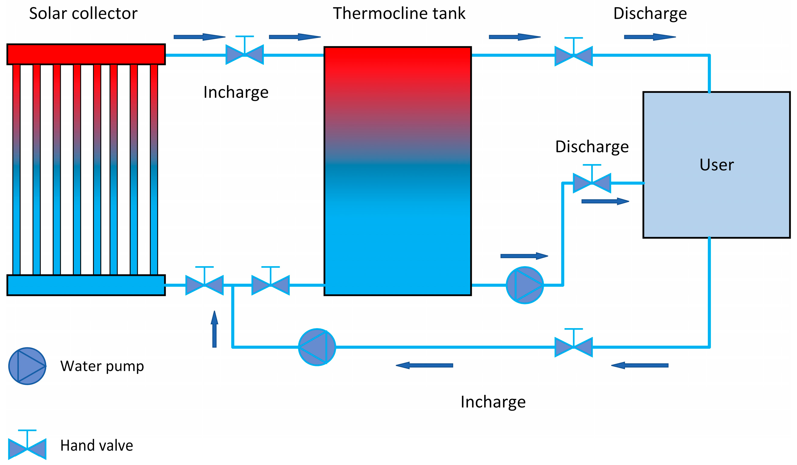
As illustrated in Figure 1, the schematic diagram represents a small-scale commercial energy storage system. The solar collector harnesses solar energy to heat cold water, which is then conveyed into the thermocline storage tank for energy storage. Within the storage tank, the coexistence of hot and cold water forms a thermocline layer. Users can extract hot water from the storage tank as needed. The thermocline storage tank is a critical component of this energy storage system, with thermal stratification being a direct factor influencing the storage efficiency. Moreover, effective thermal stratification can provide users with a larger volume of high-temperature hot water.

Figure 1.
Schematic diagram of the thermocline storage tank system.
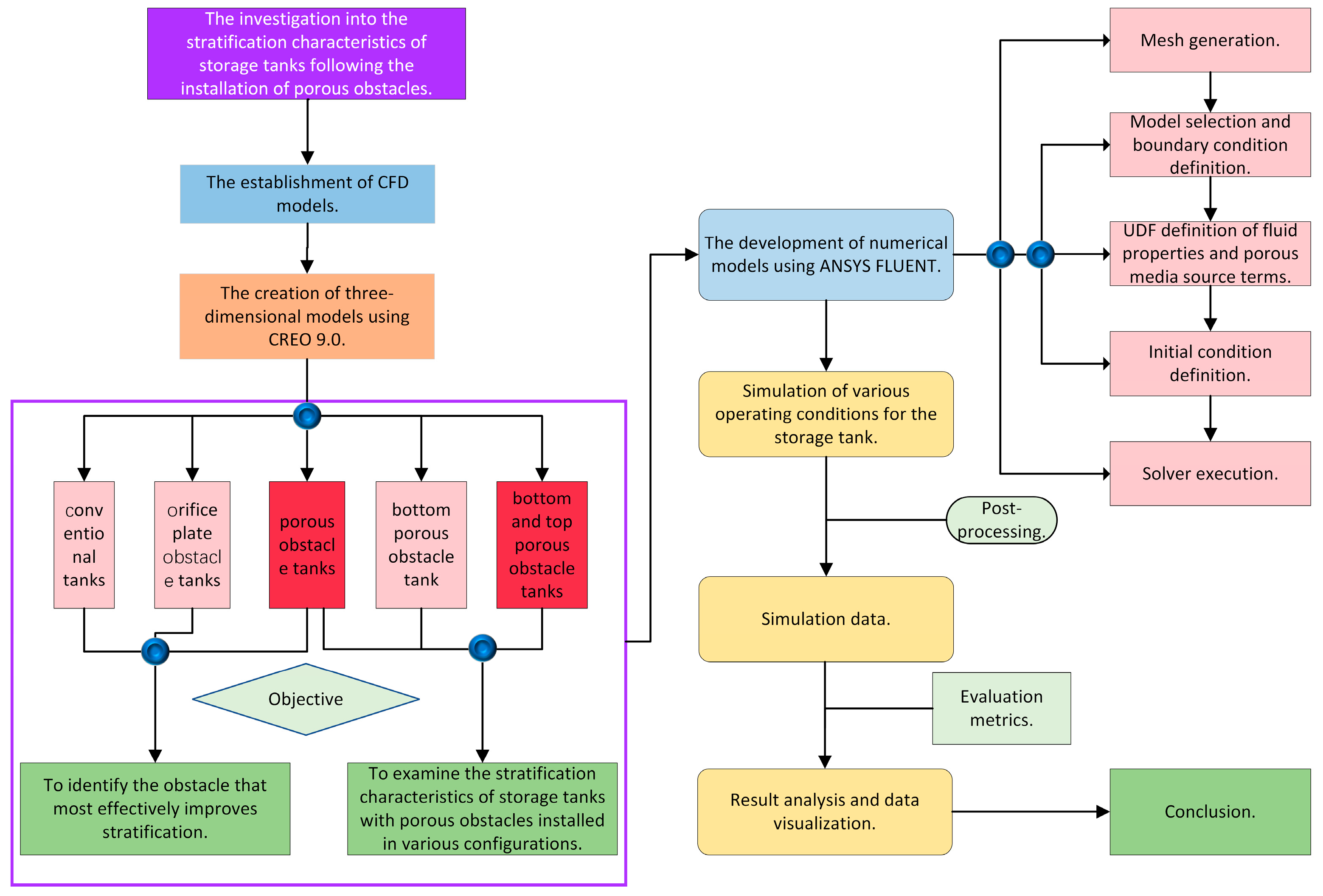
To elucidate the stratification characteristics of storage tanks with porous obstacles installed in the thermocline storage tank depicted in Figure 1, this study has established the research methodology outlined in Figure 2. The research employs CFD numerical simulation methods. On one hand, to compare with previous studies involving perforated plate obstacles and identify the internal structure that enhances stratification more effectively, and on the other hand, to explore which installation method optimally leverages the stratification improvement function of porous obstacles, this study developed five different internal configurations of storage tanks. The three-dimensional models of storage tanks with different structures were sequentially subjected to mesh generation, selection of an appropriate computational model, definition of the working fluid’s physical properties, initial condition setting, and selection of an appropriate solving algorithm. Finally, evaluation metrics were defined and applied to analyze the thermal characteristics of each storage tank.

Figure 2.
Research process.
3. Methods
3.1. Model Establishment
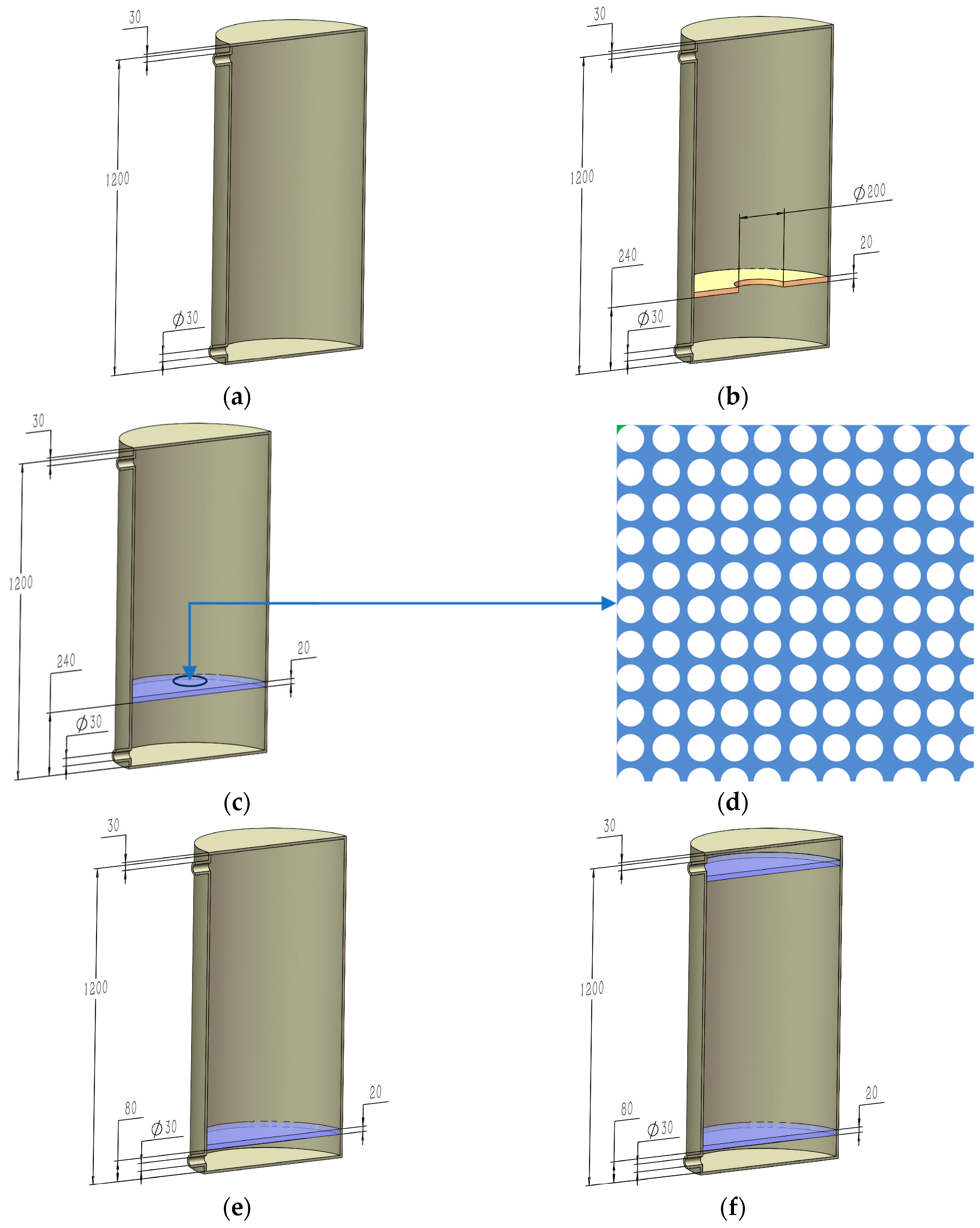
To investigate the stratification effects of porous obstacles, this study designed and comparatively analyzed five storage tanks with different internal structures. As shown in Figure 3, (a) is a traditional storage tank with no internal structures. (b) The storage tank is equipped with an orifice plate obstacle in the middle. Since the orifice plate obstacle performs better when positioned at a certain distance from the bottom of the storage tank, this study places the obstacle at a height of 330 mm from the bottom [6]. Figure 3 (c) shows a storage tank equipped with a porous obstacle. The surface shape of the porous obstacle is shown in (d), and it is filled with small holes as illustrated.
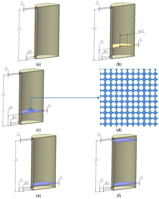
Figure 3.
(a) Type a conventional tanks; (b) Type b orifice plate obstacle tanks; (c) Type c porous obstacle tanks; (d) surface shape of porous obstacles; (e) Type e bottom porous obstacle tanks; (f) Type f bottom and top porous obstacle tanks.
The mechanisms of influence for porous obstacles differ from those of orifice plate obstacles. To investigate the impact of different installation methods of porous obstacles on stratification, this study additionally designed storage tanks with three different installation configurations of porous obstacles for energy release simulations. (c) The obstacle is positioned far from the bottom; (e) the porous obstacle is placed near the inlet; and (f) one porous obstacle is installed near both the upper and lower inlets and outlets. In this study, the porous medium model method is used to solve the equations at the locations of the porous obstacles. Therefore, the geometric structure of the porous obstacles is simplified and modeled directly as baffles. Since positioning the outlet near the bottom is more conducive to hydraulic stratification, the hot and cold water inlets and outlets are designed to be located 30 mm from the top and bottom surfaces, respectively [13].
As shown in Table 1, due to the constant variation in the c–h ratio in actual storage tanks, cases E1 to E6 are divided into two categories: the initial c–h ratio for heat release in cases E1, E2, and E3 is 0.38, while for cases E4, E5, and E6, the initial c–h ratio is 0. To obtain more information on the stratification performance of the porous obstacles, this study set three inlet flow velocities: 0.1 m/s, 0.2 m/s, and 0.3 m/s.

Table 1.
Simulation case classification and parameters.
As shown in Figure 3, the storage tank consists of three main components: the tank body, obstacles, and inlets and outlets. The cold water inlet and outlet are located at the bottom, while the hot water inlet and outlet are at the top. The geometric model was established using CREO 9.0, and the simulations were conducted using the commercial software ANSYS FLUENT 2022.
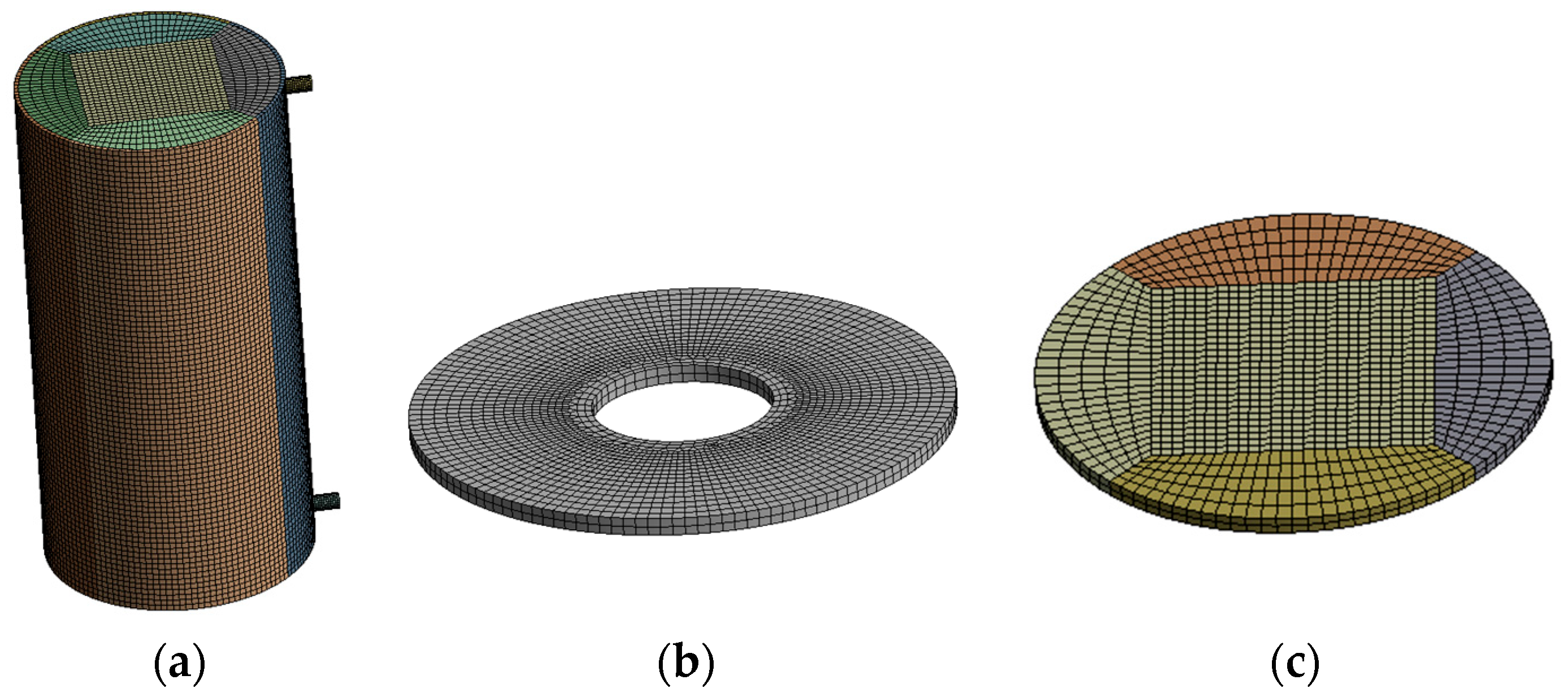
In the preprocessing stage, the geometric model was meshed using FLUENT Meshing, primarily employing hexahedral elements to generate a structured grid. Structured grids offer higher solution accuracy and faster convergence rates. The skewness of the mesh quality was controlled to be below 0.5. The mesh configuration is illustrated in Figure 4.

Figure 4.
Mesh configuration: (a) tank grid; (b) orifice plate obstacle grid; (c) porous obstacle grids.
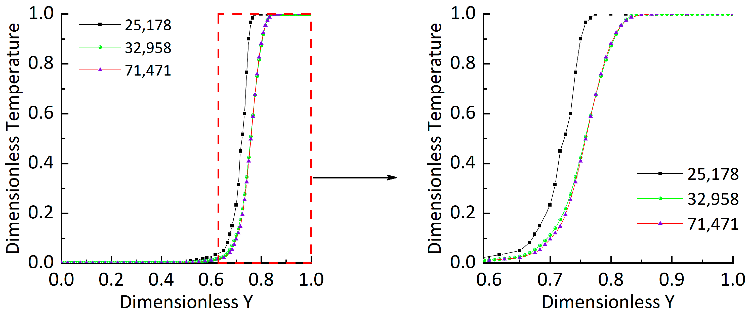
The number of mesh elements and the time step size can affect the solution accuracy. However, an excessive number of mesh elements and too small a time step can significantly increase the computational burden. Therefore, this study conducted an independence verification by setting up three sets of mesh nodes and three different time step sizes.
The mesh solution results, as shown in Figure 5, indicate that when the number of mesh elements increases to 32,958, further increases in mesh elements do not significantly affect the solution results.
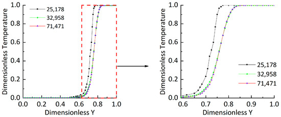
Figure 5.
Verification of time step irrelevance.
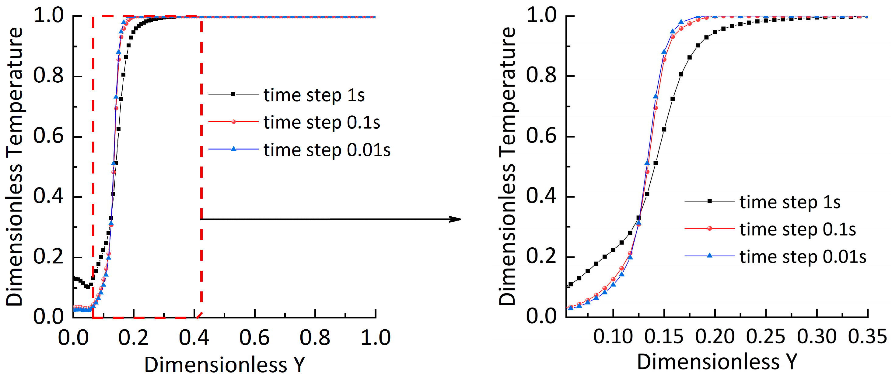
The time step solution results, as shown in Figure 6, demonstrate that when the time step is 0.1 s, further reduction in the time step does not result in significant changes in the simulation outcomes. Therefore, considering both factors, the final selection for the number of nodes and time step is 32,958 and 0.1 s, respectively.
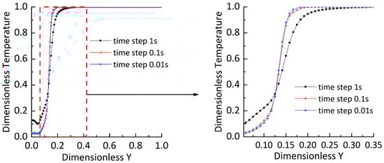
Figure 6.
Verification of time-step irrelevance.
- Reynolds Number:
- Froude Number:
Jet disturbances are the primary cause of mixing between water layers inside the storage tank. During both charging and discharging, the degree of disturbance at the outlet is mainly determined by the Reynolds number. Once the working fluid enters the storage tank, whether temperature stratification exists in the internal mixing region of the tank is primarily dependent on the Froude number [28].
The Froude number is a dimensionless number that expresses the ratio of the inertial force of a fluid to the force of gravity. When , the buoyancy force of the working fluid is greater than the gravitational force, resulting in less mixing between the hot and cold working fluids and more pronounced stratification. When , the gravitational force of the working fluid is greater than the buoyancy force, leading to significant mixing between the hot and cold working fluids, which is detrimental to stratification [29].
3.2. CFD Model
3.2.1. Mathematical Model
The continuity, momentum conservation and energy equations applicable to this study are listed and solved based on the finite volume method. The Reynolds numbers in Table 2 are all greater than 4000, indicating a turbulent flow at the cold water inlet. Due to the coexistence of laminar and turbulent flows within the storage tank, both laminar and turbulent models were tested in this study. The analysis revealed that in the central region of the tank, both models could simulate the flow field characteristics effectively. However, near the inlet and outlet, the computational results of the two models showed significant differences, with the turbulent model providing more accurate and predictive results for the turbulent effects in these areas. This observation is consistent with the description in Reference [30]. The Realizable model is an enhancement of the standard model, incorporating the constraints of turbulent stresses for better physical consistency. It exhibits excellent numerical stability even in complex geometries and under high strain rate conditions. Additionally, it offers better convergence when computing turbulence, has acceptable computational costs, and is widely used in engineering applications.
Table 2.
Hydraulic parameters at different nozzle flow rates.
In order to make the calculation results more realistic, the Realizable turbulence model was selected in the calculation settings [31].
The governing equations for this study are as follows:
Energy equation:
Considering water as an incompressible fluid, the equations are:
Momentum equation:
Energy equation:
In this study, the SIMPLE algorithm was selected for pressure-velocity coupling in the solution process. The SIMPLE algorithm achieves excellent numerical convergence by solving the velocity and pressure fields in a step-by-step manner and iteratively correcting them to satisfy the continuity equation. Its pressure correction principle enhances the physical consistency of the computational results. Combining the SIMPLE algorithm with the aforementioned Realizable model ensures the proper resolution of incompressible fluid flow, providing more accurate computational results. This combination strikes a favorable balance between convergence, physical consistency, and computational cost [31].
The discretization schemes for pressure, momentum, and energy all employ the second-order upwind scheme, The pressure relaxation factor is set to 0.3, the momentum relaxation factor to 0.7, with the residuals for the continuity equation being less than and the residuals for the energy equation being less than [32].
3.2.2. Physical Properties
The working fluid in this study is water. To ensure that the computational results accurately reflect real physical phenomena, the following physical properties of water were considered in the numerical model [18]. In ANSYS, the varying physical properties of the working fluid were simulated by defining source terms using UDFs (User-Defined Functions).
Density:
Specific heat capacity:
Kinematic viscosity:
Heat transfer coefficient:
3.2.3. Boundary Conditions
The numerical experiments in this study are divided into two categories based on the c–h ratio: one category involves energy release from a storage tank partially filled with hot water, and the other involves energy release from a storage tank completely filled with hot water.
During energy release, the inlet boundary condition is set as a velocity inlet, and the outlet is set as a pressure outlet.
In order to save computational time and improve the convergence of the results, the model is simplified as follows:
- The side walls and the top and bottom surfaces of the tank are considered adiabatic.
- At the initial moment, there is no heat conduction or heat convection between the water layers inside the tank.
- In actual stratified thermal storage tanks, the top and bottom surfaces are typically curved. In this study, they are simplified to flat surfaces.
- The working fluid is considered incompressible, and viscous dissipation and thermal radiation are neglected.
3.2.4. Porous Model
This study simplifies the porous obstacles by adding a source term to the momentum equation and solving it using the porous media model. The source term is given in Equation (17):
In Equation (17), denotes the porosity, C is the inertial drag coefficient [33], is the velocity components in different directions, and represents the directions of the velocity. Numerous studies have shown that the inertial resistance of porous obstacles is significantly smaller than the viscous resistance. Therefore, the effect of inertial resistance is neglected in the calculations. The porosity of the porous obstacles is set to 0.8, and the viscous resistance coefficient is set to .
3.3. Parameter Dimensionless
To facilitate comparative analysis between the conditions, time, depth and temperature were dimensionless as follows:
- Dimensionless time :
- Dimensionless height :
- Dimensionless temperature :
4. Evaluation Indicators
4.1. Thermocline Thickness
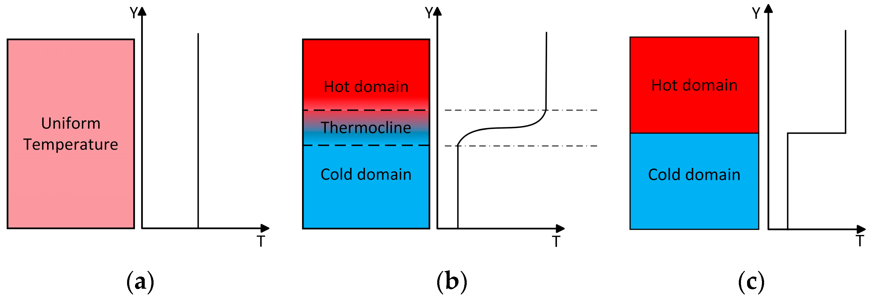
Due to the small temperature changes near the upper and lower surfaces of the thermocline, to define the stratification thickness and reflect the mixing state of the water, this study defines the thickness of the water layer occupied by the fluid with a dimensionless temperature between 0.1 and 0.85 as the thermocline [13]. Temperature stratification can be classified into three states based on the mixing condition: fully mixed, actual stratification, and ideal stratification, as shown in Figure 7.
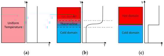
Figure 7.
Degree of temperature stratification of storage tanks with the same total energy: (a) fully mixed tanks; (b) the actual stratification tank; (c) the ideal stratification tank.
4.2. Exergy Efficiency
Exergy reflects the amount of convertible energy within a system and is a key parameter for evaluating energy quality. The mixing of cold and hot water reduces the energy quality of the system, resulting in exergy loss. In a stratified thermal storage tank, better stratification corresponds to higher exergy values. The calculation of exergy can be described as follows [36]:
Based on Equation (22), considering the variations in the physical properties of water, Equation (23) can be formulated as follows:
The exergy calculation for an ideal stratification is given by Equation (25):
The dimensionless exergy efficiency defined in this study, as shown in Equation (27), can intuitively reflect the exergy loss during the discharging process of the storage tank, thereby evaluating the energy storage efficiency of the tank.
5. Results and Discussion
In this section, the thermal storage performance during the discharge process for the respective storage tanks at c–h ratios of 0.38 and 0 will be analyzed. The evaluation of the storage tanks’ energy storage characteristics will primarily be based on the analysis of the temperature evolution within the tank, the thickness of the thermocline layer, the dimensionless exergy efficiency, and the flow trajectories of the working fluid during the discharge process.
5.1. Analysis of the Thermal Performance of the Storage Tank during Discharge with a c–h Ratio of 0.38
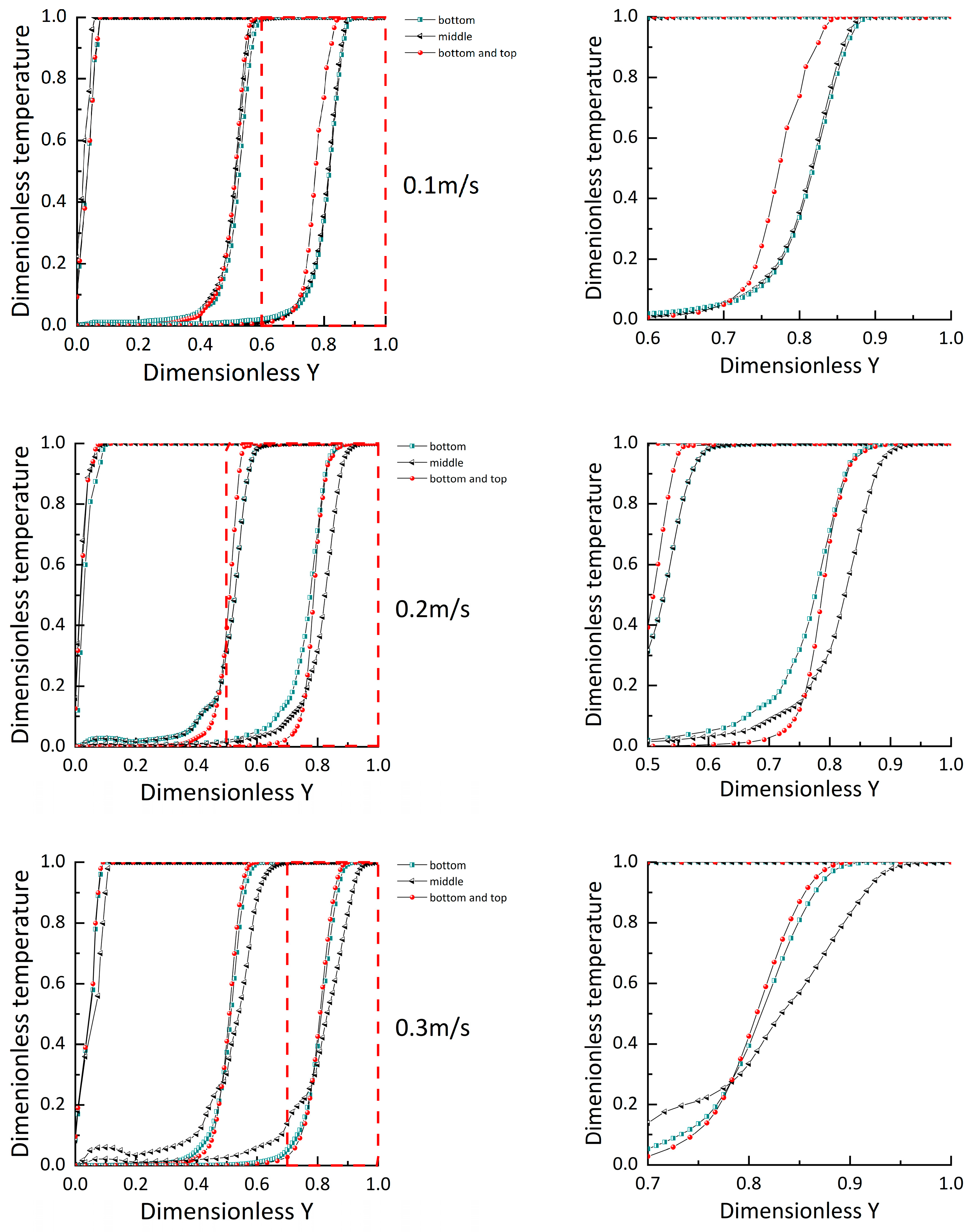
5.1.1. Time-Dependent Temperature Profile
Figure 8 shows the axial temperature distribution inside the storage tank at dimensionless times 0.001, 0.4, and 0.6 for conditions E1, E2, and E3 as listed in Table 1.
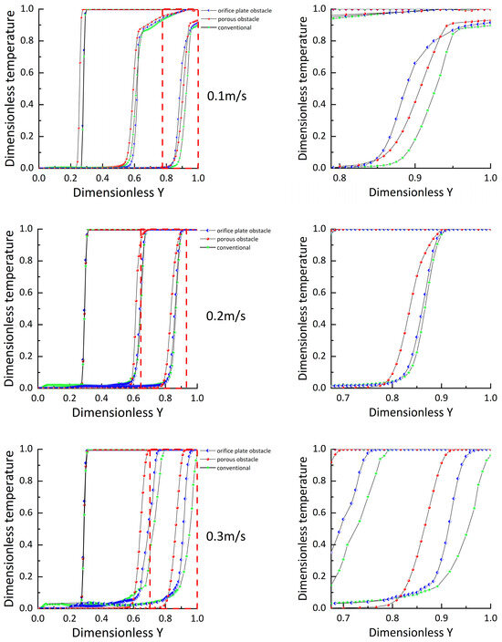
Figure 8.
Temperature distribution during discharge at different flow rates.
The axial temperature distribution for each condition exhibits two inflection points: at the first inflection point, the temperature begins to rise and the gradient increases; at the second inflection point, the temperature gradient starts to decrease, eventually rising at a slower rate until it reaches a stable temperature.
During the discharge process, the thermocline migrates upward along with the entire flow field. As shown in Figure 8, when the flow rate is 0.1 m/s, the temperature distributions inside the three types of storage tanks show minor differences due to the relatively low flow rate. However, the final hot water temperature obtained in Type c is higher than that in Type b and Type a, while the thermocline temperature in Type b is higher than that in Type a. This indicates that at this flow rate, the porous structure still demonstrates superior energy storage performance. Due to the low flow rate, the discharge time is extended, and thermal conduction in the axial direction causes the energy of the upper hot water to transfer downward, resulting in the final hot water temperature in each tank being significantly lower than the inlet hot water temperature.
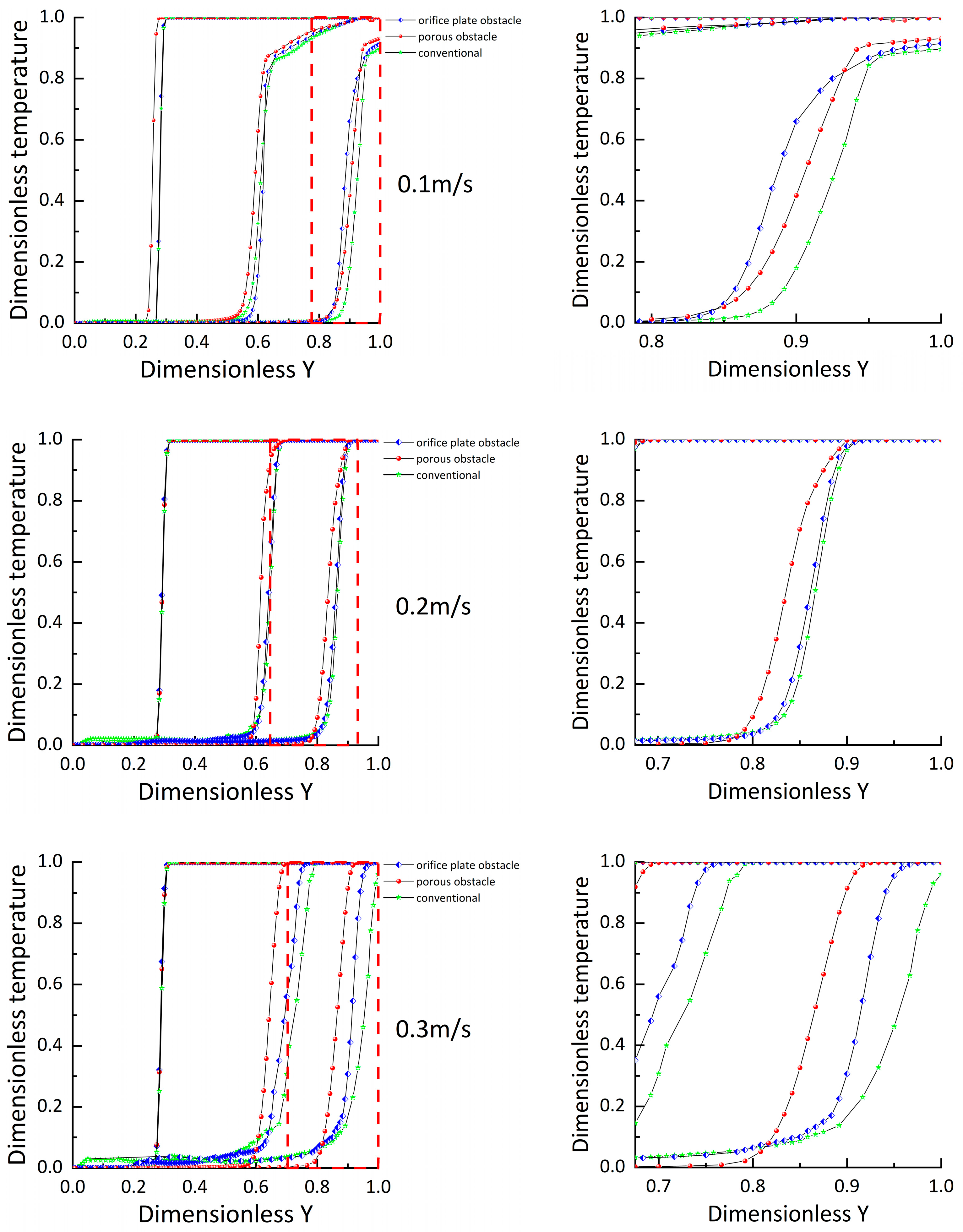
When the flow rates are 0.2 m/s and 0.3 m/s, the lower degree of mixing as cold water passes through the porous obstacles results in a higher thermocline temperature in Type c, allowing for higher-temperature water to be obtained. The thermocline temperatures in both Type b and Type c are higher than in Type a, and the low water temperatures in Type a and Type b are higher than in Type c. The range of the temperature gradient region expands as the discharge process progresses, and the greater the flow rate, the more significant the differences in the temperature gradient regions among the three types of storage tanks. At a flow rate of 0.3 m/s, the differences in energy storage among the three tanks are most pronounced. At a dimensionless time of 0.6, the proportion of high-temperature hot water in Type c is 5% higher than in Type b and 10% higher than in Type a.
5.1.2. Thermocline Thickness
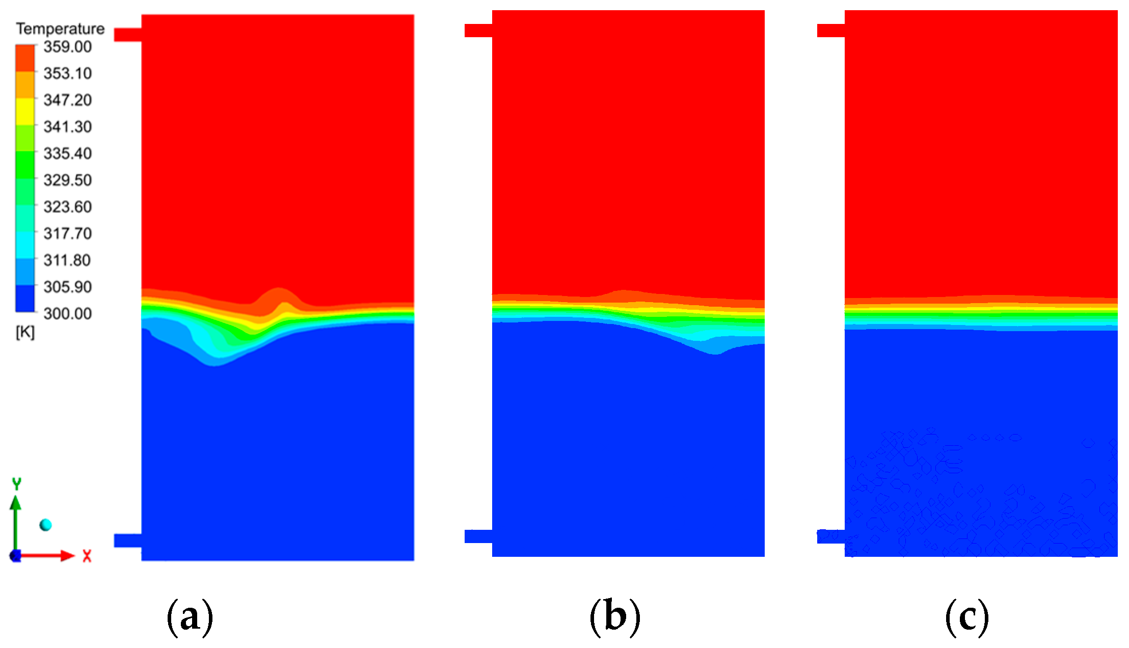
Due to the minimal differences in thermocline thickness among the three storage tanks at low flow rates, only the internal temperature contour distributions during discharge at flow rates of 0.2 m/s and 0.3 m/s are presented, as shown in Figure 9 and Figure 10.
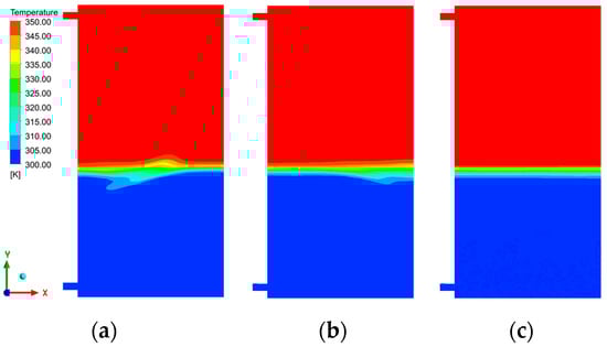
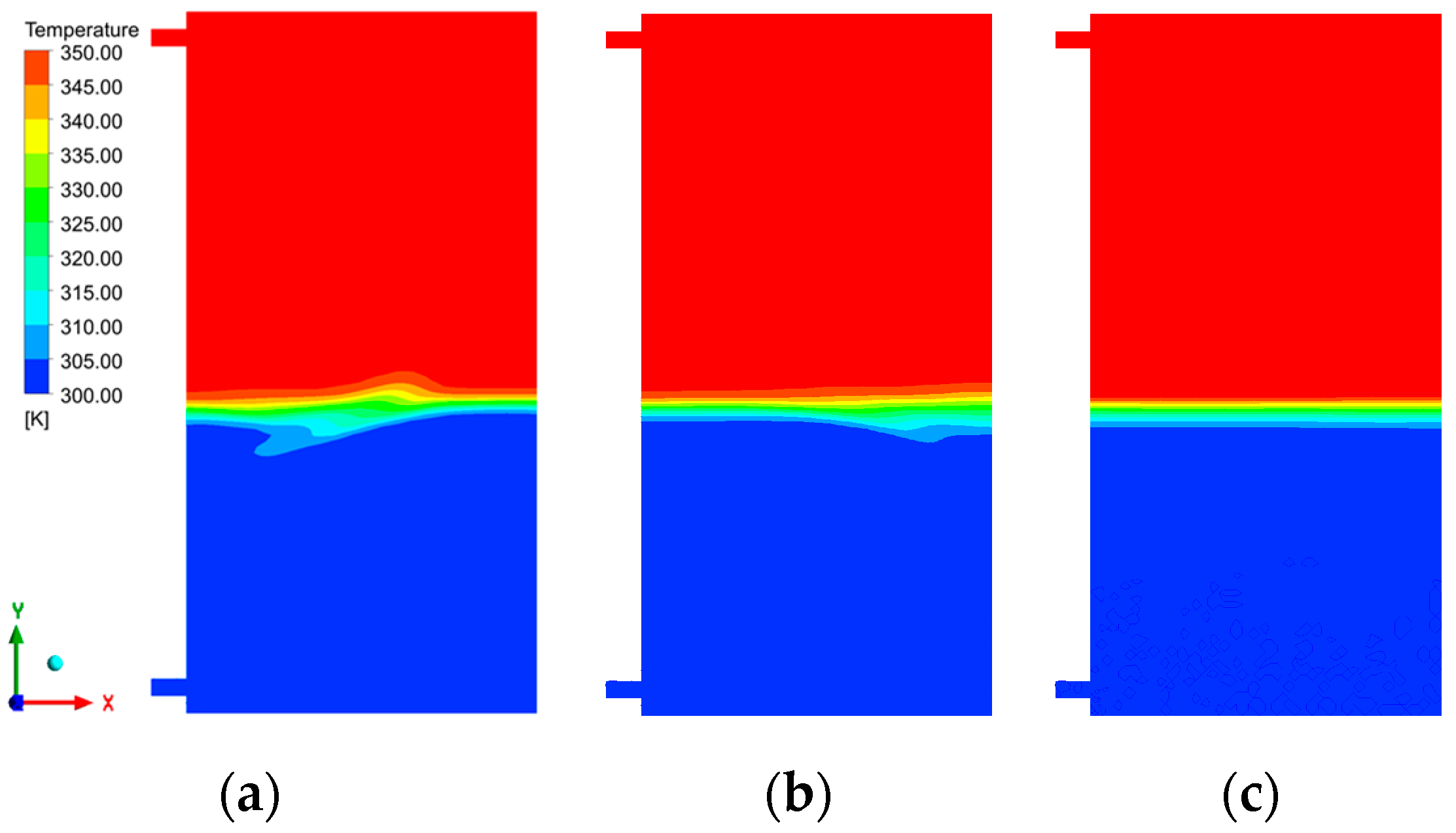
Figure 9.
Temperature contour map at a flow velocity of 0.2 m/s for c–h ratio 0.38: (a) conventional tank; (b) orifice plate obstacle tank; (c) porous obstacle tank.
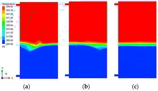
Figure 10.
Temperature contour map at a flow velocity of 0.3 m/s for c–h ratio 0.38: (a) conventional tank; (b) orifice plate obstacle tank; (c) porous obstacle tank.
At a flow rate of 0.2 m/s, Type b is less disturbed by water jet turbulence compared to Type a, with Type c being the least affected and exhibiting the most uniform thermocline distribution. As the flow rate increases, the mixing between water layers intensifies. At a flow rate of 0.3 m/s, the thermocline thickness in each storage tank significantly increases, with the thermoclines in Type b and Type a experiencing more severe turbulent disruption, while the thermocline in Type c remains uniformly distributed. At these two flow rates, the thermocline thickness in the tanks with porous obstacles is smaller. At a flow rate of 0.3 m/s, the thermocline thickness in Type a and Type b is 42% and 14.3% higher, respectively, than in Type c. Although the porous obstacles can still effectively mitigate the turbulent effects at the inlet even at higher flow rates, the increased flow rate still impacts stratification, with the thermocline thickness at 0.3 m/s being significantly greater than at 0.2 m/s.
Both porous obstacles and orifice plate obstacles can mitigate water flow disturbances inside the storage tank, but the porous structure demonstrates superior performance in this regard. As observed from the temperature contour distributions in Figure 9 and Figure 10, under the same discharge conditions, the internal thermocline in Type c storage tanks exhibits the highest uniformity, whereas. Type a storage tanks show the most uneven thermocline distribution, experiencing greater fluctuations. Although an increase in flow velocity results in a thicker thermocline, this phenomenon remains unchanged.
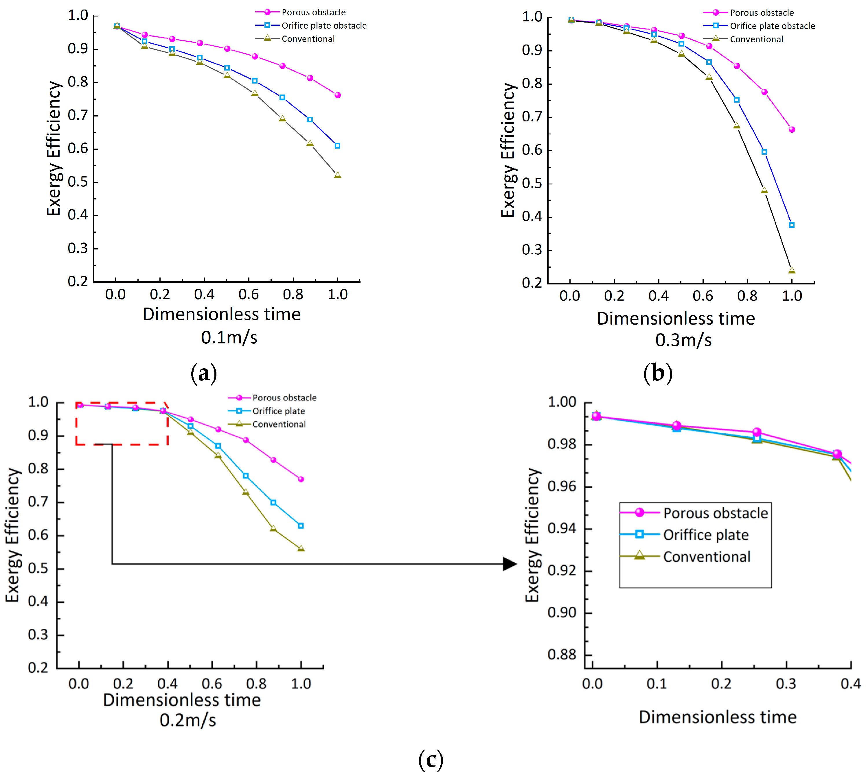
5.1.3. Exergy Efficiency
Figure 11 shows the exergy efficiency inside the storage tanks for E1, E2, and E3. Different structures result in different internal flow field characteristics, leading to differences in exergy efficiency at the beginning of the discharge process. Storage tanks with internal obstacles perform better in terms of energy storage, with higher exergy efficiency. However, at the same time, Type c has the highest exergy efficiency, Type a has the lowest, and the porous obstacles demonstrate the best energy storage performance.
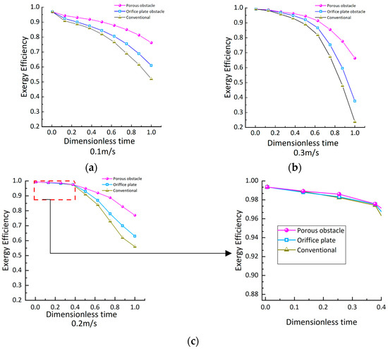
Figure 11.
Exergy efficiency: (a) at a flow rate of 0.1 m/s; (b) at a flow rate of 0.3 m/s; (c) at a flow rate of 0.2 m/s.
The differences in exergy efficiency among the storage tanks increase over time. At a flow rate of 0.3 m/s, the exergy efficiency inside the tanks is the lowest. Under the combined influence of structure and thermal conduction, the storage tanks exhibit higher exergy efficiency at a flow rate of 0.2 m/s.
Water mixing and axial heat conduction between different water layers both affect exergy efficiency. At a flow rate of 0.1 m/s, a longer time is required to reach the same heat release state, which intensifies heat transfer in the vertical direction of the water body and lowers the exergy efficiency. This can explain why the exergy efficiency at a flow rate of 0.2 m/s is higher than at 0.1 m/s. At a flow rate of 0.3 m/s, the flow rate becomes the main factor reducing energy storage efficiency, resulting in the lowest exergy efficiency at this flow rate.
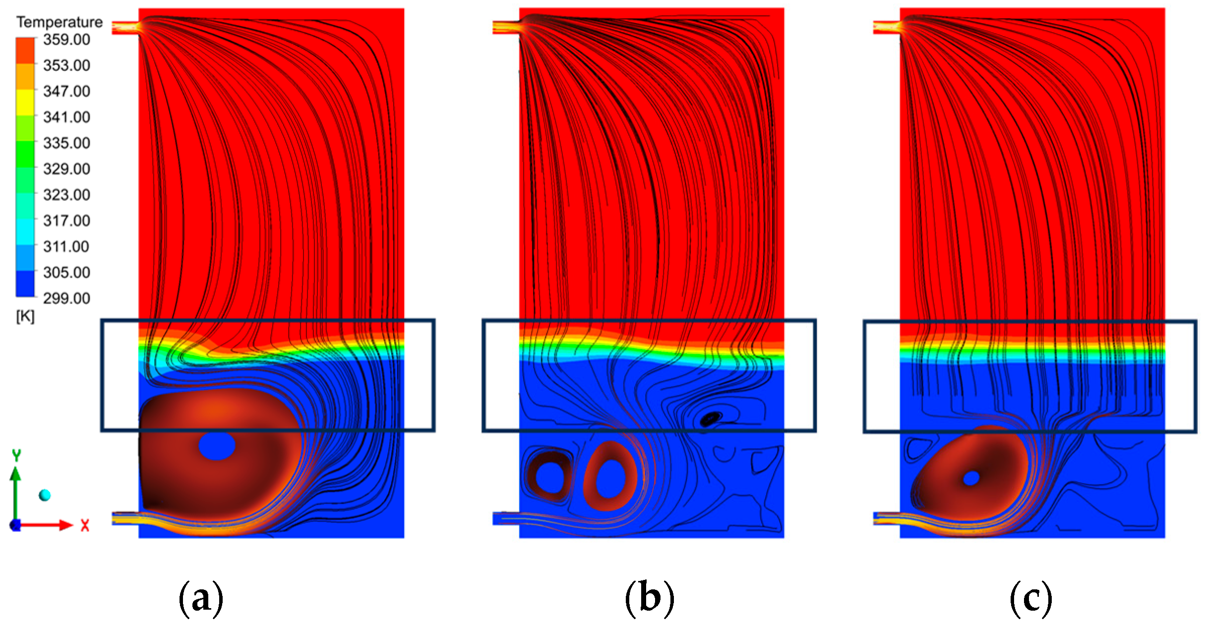
5.1.4. Characteristics of the Internal Flow Field
Figure 12 shows the fluid flow trajectories inside the tanks for E1, E2, and E3 at a flow rate of 0.3 m/s. When cold water is injected, it causes agitation. Traditional thermal storage tanks do not obstruct the jet, resulting in more severe disturbances. Type b is also affected by agitation, but some of the disturbances are confined to the area below the orifice plate obstacle, improving the turbulence effects above the baffle. In Type c, the disturbance area is confined below the obstacle, with no significant vortex formation above the obstacle. Additionally, the porous structure’s obstruction leads to a more uniform flow velocity distribution as the water passes through the obstacle.

Figure 12.
Internal streamline diagram at a flow velocity of 0.3 m/s for c–h ratio 0.38: (a) conventional tank; (b) orifice plate obstacle tank; (c) porous obstacle tank.
The orifice plate obstacle can hinder jet disturbances, but there are still some areas above the obstacle that cannot avoid the effects of fluid agitation. The porous structure not only better confines the jet disturbance area but also stabilizes the internal flow field movement within the storage tank.
5.2. Analysis of the Thermal Performance of the Storage Tank during Discharge with a c–h Ratio of 0
5.2.1. Time-Dependent Temperature Profile
Figure 13 shows the axial temperature distribution inside the tanks for E4, E5, and E6 during the discharge process at dimensionless times of 0.01, 0.5, and 0.8.
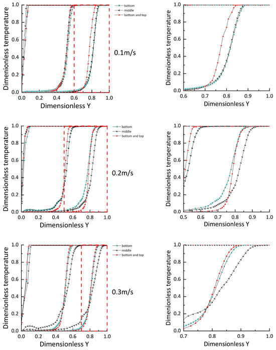
Figure 13.
Temperature distribution during discharge at different flow rates.
When the obstacle is near the bottom, less water participates in the mixing process. Under different flow rates, the thermocline temperature gradient in Type c is the smallest and occupies the largest range. When the obstacle is near the bottom, the thermocline temperature gradient region in the storage tank is smaller, and more high-temperature hot water can be obtained in the end. This difference is further amplified at higher flow rates. At a flow rate of 0.3 m/s, the difference in the temperature gradient region range between the middle obstacle storage tank and the bottom obstacle storage tank is the greatest.
Installing a porous obstacle near both the top and bottom outlets of the storage tank, compared to installing a porous obstacle only at the bottom outlet, further improves the stratification performance. In all simulations, Type f exhibits the greatest thermocline gradient and occupies a smaller water layer thickness.
5.2.2. Thermocline Thickness
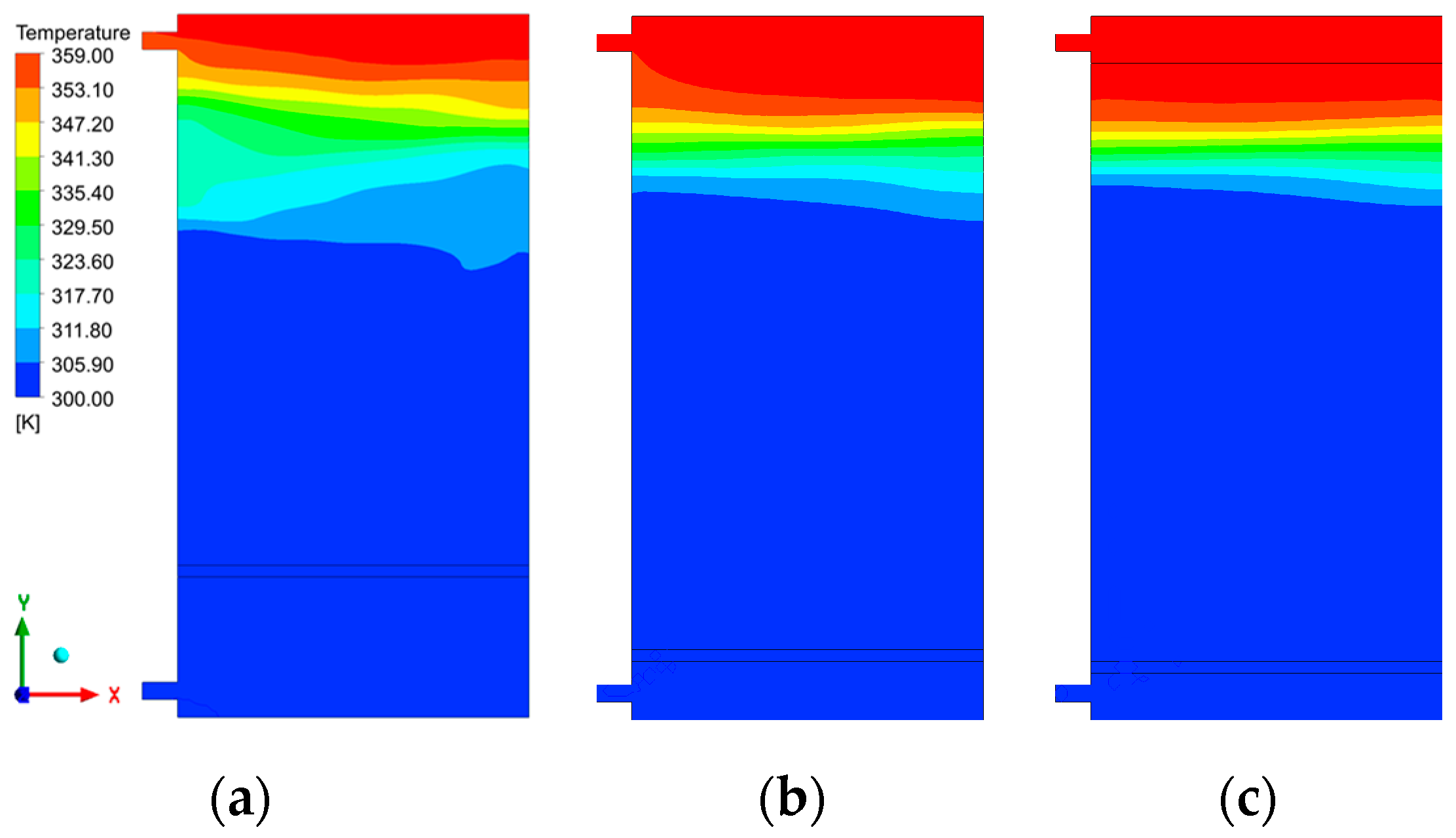
Figure 14 shows the temperature contour distribution inside the storage tank for E4, E5, and E6 during energy discharge at a flow rate of 0.3 m/s. It can be observed that Type c has the largest thermocline thickness and the most uneven temperature distribution. In contrast, Type e and Type f experience less disturbance, resulting in better water temperature stratification. Type f, which includes an additional porous obstacle below the hot water inlet and outlet, further inhibits the growth of the thermocline, resulting in the smallest thermocline thickness.
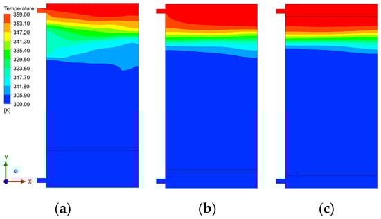
Figure 14.
Temperature contour map at a flow velocity of 0.3 m/s for c–h ratio 0: (a) Porous obstacle in the middle; (b) Porous obstacle near the bottom; (c) Porous obstacles near both the bottom and top.
The position of the porous structure directly affects the degree of mixing between water layers. At a flow rate of 0.2 m/s, the thermocline thickness of Type e is 106% higher than that of Type f. At a flow rate of 0.3 m/s, the thermocline thicknesses of Type c and Type e are 133% and 17% higher than that of Type f, respectively.
5.2.3. Exergy Efficiency
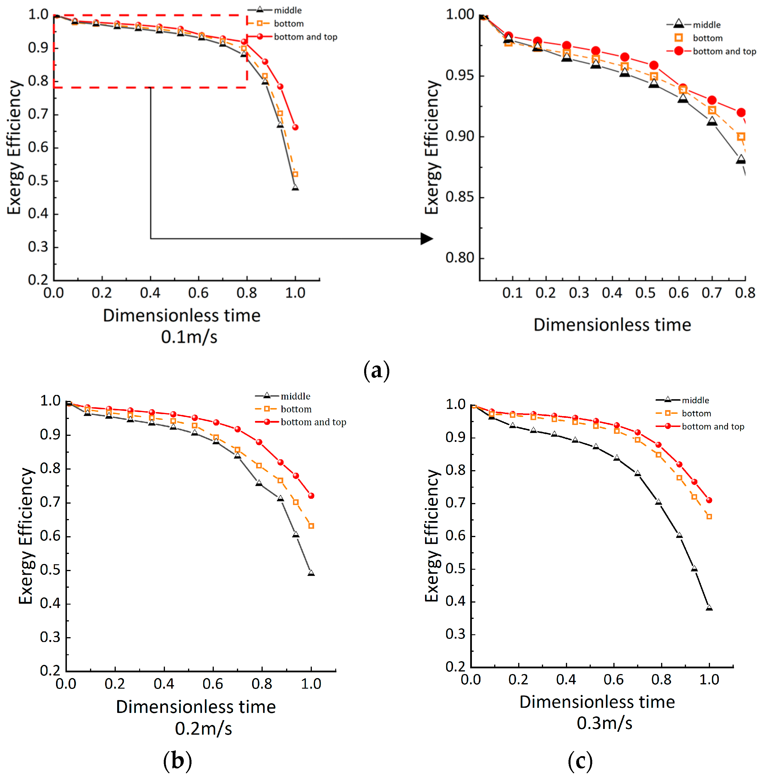
The internal exergy efficiency of the storage tanks during the discharge process for E4, E5, and E6 is shown in Figure 15. When discharging at different flow rates, the storage tank with porous obstacles installed at both the top and bottom outlets has the highest exergy efficiency among the experiments in the same group, followed by the tank with the obstacle installed near the bottom.
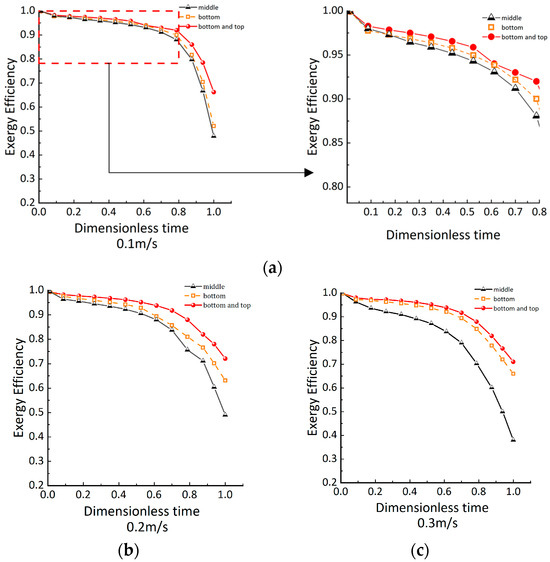
Figure 15.
Exergy efficiency: (a) at a flow rate of 0.1 m/s; (b) at a flow rate of 0.2 m/s; (c) at a flow rate of 0.3 m/s.
Under the influence of flow rate and thermal conduction, the exergy efficiency of the storage tank is highest at a flow rate of 0.2 m/s. At the same discharge state, at the final moment of 0.3 m/s, the exergy efficiency of Type e and Type f is higher than that at 0.1 m/s. This differs from the discharge when the initial c–h ratio is 0.38. However, this phenomenon is also caused by excessive axial thermal conduction due to the prolonged discharge time.
Under high flow rates, the storage tank with a porous obstacle at the bottom still maintains a relatively high exergy efficiency. As the flow rate increases, the difference in exergy efficiency between Type c, Type e, and Type f becomes larger. The difference in exergy efficiency between the tanks is smallest at 0.1 m/s and largest at 0.3 m/s.
5.2.4. Characteristics of the Internal Flow Field
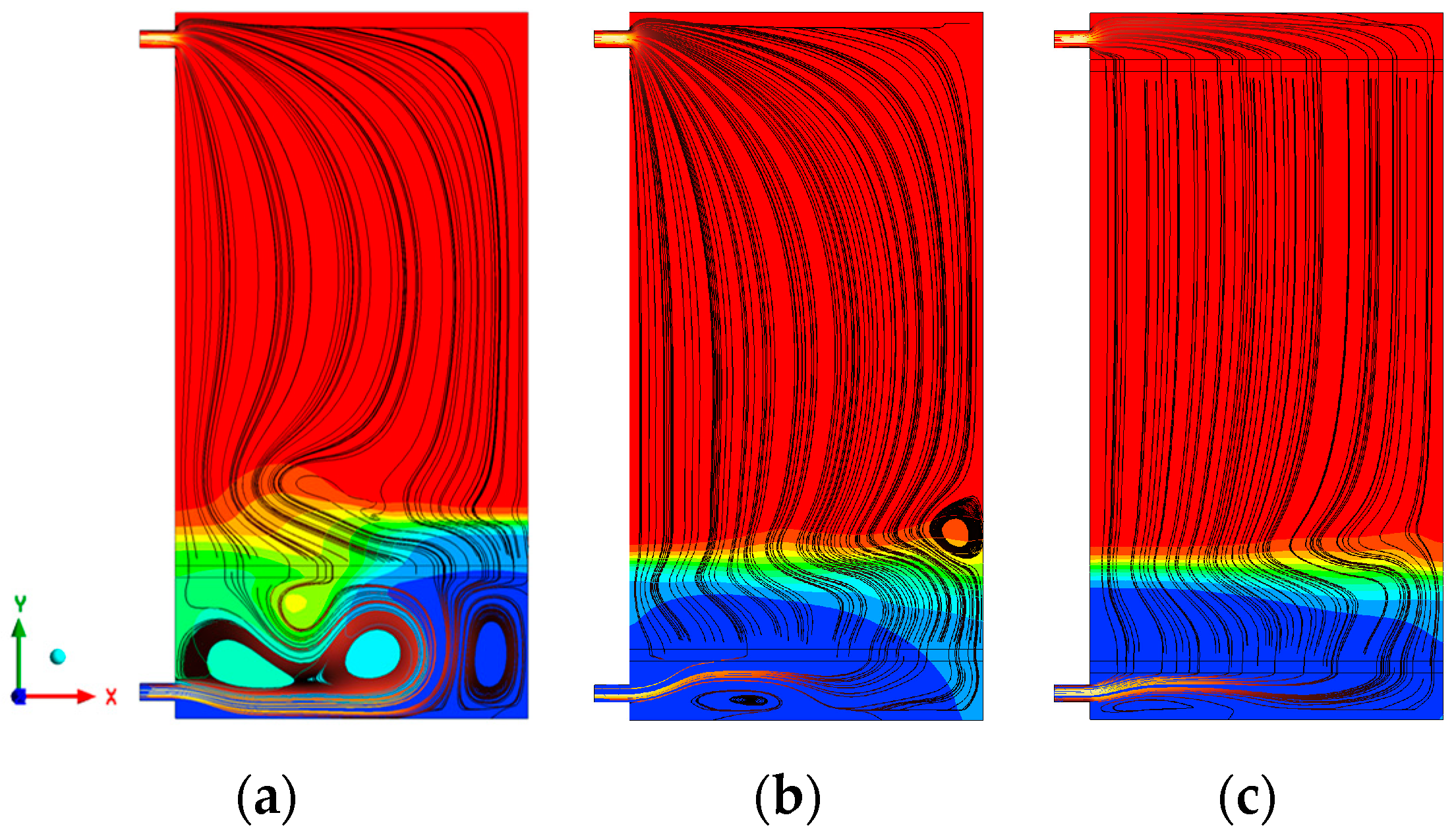
The internal flow field characteristics of E4, E5, and E6 during discharge at a flow rate of 0.3 m/s are shown in Figure 16.

Figure 16.
Internal streamline diagram at a flow velocity of 0.3 m/s for c–h ratio 0: (a) porous obstacle in the middle; (b) porous obstacle near the bottom; (c) porous obstacles near both the bottom and top.
Due to the different installation positions of the obstacles, the vortex influence range in Type c is larger. In Type e and Type f, where the porous obstacles are near the bottom, the vortex influence range is smaller, and the streamlines above the obstacles are uniform with stable flow rates. When the obstacle is farther from the outlet, more water is agitated, leading to greater disruption of stratification.
Installing the porous obstacle near the bottom effectively limits the mixing range of the water, making it more suitable for storage tanks discharging with different c–h ratios in practical applications.
When water flows out, it can cause uneven flow velocity distribution within the internal flow field, thereby disrupting stratification. In Type f, porous obstacles are installed at both the top and bottom outlets, which twice hinder the internal fluid disturbances, improving the agitation effects caused by hot water flowing out at the outlet. As can be seen from Figure 16, the streamlined distribution of Type f is significantly more uniform than that of Type b. The two porous obstacles further stabilize the fluid flow in the internal flow field, which further helps to reduce the thickness of the thermocline and maintain the thermocline.
This section analyzes the energy storage characteristics of storage tanks with different structures. In Section 4.1, by comparing the stratification effects of E1, E2, and E3, it is concluded that porous obstacles are superior to orifice plate obstacles in promoting thermal stratification performance. In Section 4.2, the stratification effects of E4, E5, and E6 are discussed, leading to the determination of the optimal installation position for porous obstacles.
6. Conclusions
To enhance thermal stratification and improve energy storage efficiency in thermocline storage tanks, this study designed a system with porous obstacles installed inside the storage tank and investigated its stratification characteristics. Two types of discharge simulations were conducted based on different c–h ratios: one set involved simulations of traditional storage tanks, orifice plate obstacle storage tanks, and porous obstacle storage tanks with an initial c–h ratio of 0.38; the other set involved discharge simulations of storage tanks with different installation positions of porous obstacles with an initial c–h of 0. Through simulations analyzing thermocline thickness, exergy efficiency, and internal flow fields, the stratification effects of each storage tank were evaluated.
The conclusions can be summarized as follows:
- (1)
- Installing obstacles inside the tank can partially hinder the mixing of hot and cold water, thereby improving stratification. Among these, porous obstacles exhibit superior stratification performance. At a flow rate of 0.3 m/s, the thermocline thickness of traditional and orifice plate obstacle tanks is 42% and 14.3% higher, respectively, than that of tanks with porous obstacles. A porous obstacle can limit the disturbance range of the jet, ensuring that the fluid above is not subjected to intense turbulence.
- (2)
- The fluid below the porous obstacle experiences intense mixing. When the obstacle is near the inlet, it can reduce the mixing region of the fluid. Considering that the c–h ratio inside the storage tank varies in practice applications, installing the porous obstacle near the bottom is more reasonable, as it can adapt to different discharge and charge states.
- (3)
- Adding porous obstacles at both the top and bottom outlets can reduce the disturbance at the outlets, further improving stratification. At a flow rate of 0.3 m/s, the thermocline thickness is 17% higher when there is only one porous obstacle compared to when there are two porous obstacles.
- (4)
- When the flow rate is too low, axial thermal conduction within the storage tank becomes the main factor reducing energy storage efficiency. Therefore, selecting an appropriate flow rate is crucial when using the storage tank.
Author Contributions
Conceptualization, J.T and S.H.; methodology, J.T. and S.H.; software, J.T.; formal analysis, Z.D.; supervision, data curation, J.T.; writing—original draft preparation, J.T.; writing—review and editing, J.T.; All authors have read and agreed to the published version of the manuscript.
Funding
This research received no external funding.
Institutional Review Board Statement
Not applicable.
Informed Consent Statement
Not applicable.
Data Availability Statement
The raw data supporting the conclusions of this article will be made available by the authors on request.
Acknowledgments
This research appreciates the supervision and technical support from the relevant personnel.
Conflicts of Interest
The authors declare no conflicts of interest.
Nomenclature
| Inertial resistance coefficient | ||
| Specific heat of water | ||
| The initial ratio of cold water to hot water | ||
| Temperature of cold water | ||
| Tank diameter | ||
| Energy of tank | ||
| Body force acceleration | ||
| Froude number | ||
| Ideal stratification | ||
| Gravitational acceleration | ||
| Total height of the water layer | ||
| Thermocline thickness | ||
| Temperature of hot water | ||
| Number of water layers | ||
| Number of water layers | ||
| Height of the tank wall surface | ||
| kg | Mass of the water in the i-th layer | |
| Pressure | ||
| Volumetric flow rate at the inlet | ||
| Circumferential radius of the upper and lower bases | ||
| Reynolds number | ||
| Source term of the momentum equation | ||
| Dimensionless time | ||
| s | Discharge actual time | |
| Dimensionless temperature | ||
| k | Temperature of the water in the k-th layer | |
| k | Temperature of the cold water | |
| k | Temperature of the hot water at the inlet | |
| k | Volume-averaged temperature | |
| Velocity in -direction | ||
| Velocity in -direction | ||
| Velocity in -direction | ||
| Dimensionless height | ||
| Density | ||
| Density | ||
| Stress tensor vector | ||
| , , | Orthogonal directions in Cartesian coordinates | |
| Thermal conductivity | ||
| Exergy | ||
| Actual exergy | ||
| Porosity | ||
| Exergy efficiency | ||
| Coefficient of volumetric expansion |
References
- Cocco, D.; Serra, F. Performance comparison of two-tank direct and thermocline thermal energy storage systems for 1 MWe class concentrating solar power plants. Energy 2015, 81, 526–536. [Google Scholar] [CrossRef]
- Savicki, D.L.; Vielmo, H.A.; Krenzinger, A. Three-dimensional analysis and investigation of the thermal and hydrodynamic behaviors of cylindrical storage tanks. Renew. Energy 2011, 36, 1364–1373. [Google Scholar] [CrossRef]
- Njoku, H.O.; Ekechukwu, O.V.; Onyegegbu, S.O. Analysis of stratified thermal storage systems: An overview. Heat Mass Transf. 2014, 50, 1017–1030. [Google Scholar] [CrossRef]
- Chandra, Y.P. Stratification analysis of domestic hot water storage tanks. Energy Build 2019, 187, 110–131. [Google Scholar] [CrossRef]
- Shaikh, W.; Wadegaonkar, A.; Kedare, S.B.; Bose, M. Numerical simulation of single media thermocline based storage system. Sol. Energy 2018, 174, 207–217. [Google Scholar] [CrossRef]
- Erdemir, D.; Altuntop, N. Improved thermal stratification with obstacles placed inside the vertical mantled hot water tanks. Appl. Therm. Eng. 2016, 100, 20–29. [Google Scholar] [CrossRef]
- Gao, L.; Lu, H.L.; Sun, B.Z.; Che, D.Y.; Dong, L.W. Numerical and experimental investigation on thermal stratification characteristics affected by the baffle plate in thermal storage tank. J. Energy Storage 2021, 34, 13. [Google Scholar] [CrossRef]
- Erdemir, D.; Atesoglu, H.; Altuntop, N. Experimental investigation on enhancement of thermal performance with obstacle placing in the horizontal hot water tank used in solar domestic hot water system. Renew. Energy 2019, 138, 187–197. [Google Scholar] [CrossRef]
- Altuntop, N.; Arslan, M.; Ozceyhan, V.; Kanoglu, M. Effect of obstacles on thermal stratification in hot water storage tanks. Appl. Therm. Eng. 2005, 25, 2285–2298. [Google Scholar] [CrossRef]
- Yin, Z.H.; Kuihua; Gao, M.; Qi, J. Simulations and Exergy Analysis on Performance of Single Thermocline Energy Storage Tank With the Thermal Insulation Panel. Proc. CSEE 2021, 41, 236–246. [Google Scholar]
- Feng, H.M.; Li, H.T.; He, S.Y.; Qi, J.H.; Han, K.H.; Gao, M. Numerical simulation on thermal stratification performance in thermocline water storage tank with multi-stage middle perforated obstacles. Therm. Sci. Eng. Prog. 2022, 35, 12. [Google Scholar] [CrossRef]
- Wang, X.; He, Z.; Xu, C.; Du, X.Z. Dynamic Simulations on Simultaneous Charging/Discharging Process of Water Thermocline Storage Tank. Proc. CSEE 2019, 39, 5989–5998. [Google Scholar]
- Moncho-Esteve, I.J.; Gasque, M.; González-Altozano, P.; Palau-Salvador, G. Simple inlet devices and hot water storage tank their influence on thermal stratification in a. Energy Build. 2017, 150, 625–638. [Google Scholar] [CrossRef]
- Wang, Z.L.; Zhang, H.; Dou, B.L.; Huang, H.J.; Wu, W.D.; Wang, Z.Y. Experimental and numerical research of thermal stratification with a novel inlet in a dynamic hot water storage tank. Renew. Energy 2017, 111, 353–371. [Google Scholar] [CrossRef]
- Xu, C.; Liu, M.; Jiao, S.; Tang, H.Y.; Yan, J.J. Experimental study and analytical modeling on the thermocline hot water storage tank with radial plate-type diffuser. Int. J. Heat Mass Transf. 2022, 186, 14. [Google Scholar] [CrossRef]
- Ulrike, J. Thermal stratification in small solar domestic storage tanks caused by draw-offs. Sol. Energy 2005, 78, 291–300. [Google Scholar]
- Devore, N.; Yip, H.; Rhee, J. Domestic hot water storage tank: Design and analysis for improving thermal stratification. J. Sol. Energy Eng. 2013, 135, 040905. [Google Scholar] [CrossRef]
- Lake, A.; Rezaie, B. Energy and exergy efficiencies assessment for a stratified cold thermal energy storage. Appl. Energy 2018, 220, 605–615. [Google Scholar] [CrossRef]
- Bai, Y.K.; Yang, M.; Wang, Z.F.; Li, X.X.; Chen, L.F. Thermal stratification in a cylindrical tank due to heat losses while in standby mode. Sol. Energy 2019, 185, 222–234. [Google Scholar] [CrossRef]
- Hoffmann, J.F.; Fasquelle, T.; Goetz, V.; Py, X. A thermocline thermal energy storage system with filler materials for concentrated solar power plants: Experimental data and numerical model sensitivity to different experimental tank scales. Appl. Therm. Eng. 2016, 100, 753–761. [Google Scholar] [CrossRef]
- Chung, J.D.; Cho, S.H.; Tae, C.S.; Yoo, H. The effect of diffuser configuration on thermal stratification in a rectangular storage tank. Renew. Energy 2008, 33, 2236–2245. [Google Scholar] [CrossRef]
- Li, Q.; Huang, X.Q.; Tai, Y.H.; Gao, W.F.; Wenxian, L.; Liu, W.M. Thermal stratification in a solar hot water storage tank with mantle heat exchanger. Renew. Energy 2021, 173, 1–11. [Google Scholar] [CrossRef]
- Chandra, Y.P.; Matuska, T. Numerical prediction of the stratification performance in domestic hot water storage tanks. Renew. Energy 2020, 154, 1165–1179. [Google Scholar] [CrossRef]
- Castell, A.; Medrano, M.; Solé, C.; Cabeza, L.F. Dimensionless numbers used to characterize stratification in water tanks for discharging at low flow rates. Renew. Energy 2010, 35, 2192–2199. [Google Scholar] [CrossRef]
- Mawire, A.; Taole, S.H. A comparison of experimental thermal stratification parameters for an oil/pebble-bed thermal energy storage (TES) system during charging. Appl. Energy 2011, 88, 4766–4778. [Google Scholar] [CrossRef]
- Göppert, S.; Lohse, R.; Urbaneck, T.; Schirmer, U.; Platzer, B.; Steinert, P. New computation method for stratifcation pipes of solar storage tanks. Sol. Energy 2009, 83, 1578–1587. [Google Scholar] [CrossRef]
- Andersen, E.; Furbo, S.; Fan, J. Multilayer fabric stratifcation pipes for solar tanks. Sol. Energy 2007, 81, 1219–1226. [Google Scholar] [CrossRef]
- Baeten, B.; Confrey, T.; Pecceu, S.; Rogiers, F.; Helsen, L. A validated model for mixing and buoyancy in stratified hot water storage tanks for use in building energy simulations. Appl. Energy 2016, 172, 217–229. [Google Scholar] [CrossRef]
- Ge, Z.H.; Zhang, F.Y.; Zhang, Y.J. Simulation on Performance Improvement of Single Thermocline Energy Storage Tank. Proc. CSEE 2019, 39, 773–781. [Google Scholar]
- Gasque, M. Study of the influence of inner lining material on thermal stratification in a hot water storage tank. Appl. Therm. Eng. 2015, 75, 344–356. [Google Scholar] [CrossRef]
- Yaïci, W.; Ghorab, M.; Entchev, E.; Hayden, S. Three-dimensional unsteady CFD simulations of a thermal storage tank performance for optimum design. Appl. Therm. Eng. 2013, 60, 152–163. [Google Scholar] [CrossRef]
- Shin, M.S.; Kim, H.S.; Jang, D.S.; Lee, S.N.; Lee, Y.S.; Yoon, H.G. Numerical and experimental study on the design of a stratifed thermal storage system. Appl. Therm. Eng. 2004, 24, 17–27. [Google Scholar] [CrossRef]
- Rosen, M.A. The exergy of stratified thermal energy storages. Sol. Energy 2001, 71, 173–185. [Google Scholar] [CrossRef]
- Kaloudis, E.; Grigoriadis DG, E.; Papanicolaou, E.; Panidis, T. Large eddy simulation of thermocline flow phenomena and mixing during discharging of an initially homogeneous or stratified storage tank. Eur. J. Mech. B. Fluids 2014, 48, 94–114. [Google Scholar] [CrossRef]
- Musser, A.; Bahnfleth, W.P. Parametric study of charging inlet diffuser performance in stratified chilled water storage tanks with radial diffusers: Part1-model development and validation. HVAC&R Res. 2001, 7, 31–49. [Google Scholar]
- Louise, J.S.; Simon, F. Entrance effects in solar storage tanks. Sol. Energy 2003, 75, 337–348. [Google Scholar]
Disclaimer/Publisher’s Note: The statements, opinions and data contained in all publications are solely those of the individual author(s) and contributor(s) and not of MDPI and/or the editor(s). MDPI and/or the editor(s) disclaim responsibility for any injury to people or property resulting from any ideas, methods, instructions or products referred to in the content. |
© 2024 by the authors. Licensee MDPI, Basel, Switzerland. This article is an open access article distributed under the terms and conditions of the Creative Commons Attribution (CC BY) license (https://creativecommons.org/licenses/by/4.0/).