Article

Aerodynamic Characteristics and Its Sensitivity Analysis of a Cylindrical Projectile at Different Incidences

1
School of Energy and Power Engineering, Nanjing University of Science and Technology, Nanjing 210094, China
2
Beijing Institute of Space Long March Vehicle, Beijing 100076, China
*
Author to whom correspondence should be addressed.
Appl. Sci. 2024, 14(15), 6683; https://doi.org/10.3390/app14156683
Submission received: 4 June 2024 / Revised: 15 July 2024 / Accepted: 19 July 2024 / Published: 31 July 2024
(This article belongs to the Section Fluid Science and Technology)

Abstract

:
The accurate evaluation of aerodynamic characteristics is a prerequisite and foundation for the design of high-performance aerodynamic shapes, navigation guidance, and strength of projectiles. The nonlinearity of aerodynamic calculations for a projectile is high, and the modeling and simulation are difficult, especially under the high-angle of attack flight conditions. Small variations in flight conditions, and structural parameters, etc., may cause large deviations in aerodynamic responses. Taking a small cylindrical projectile as an example, and to realize its attitude control, it is necessary to conduct aerodynamic characteristics analysis on it and analyze the main influencing factors of its aerodynamic characteristics parameters. In this paper, the finite volume method is used to solve the three-dimensional unsteady N-S equation, combined with the SST k-ω turbulence model, the overlapping grid technology, and the forced pitching vibration method, and the aerodynamic characteristics analysis model of the projectile is established, which realizes the accurate simulation of the surrounding flow field, aerodynamic coefficients, and dynamic derivative of the projectile under different flight conditions. On this basis, the Sobol global sensitivity analysis method based on the augmented radial basis function surrogate model of aerodynamics characteristics and Latin hypercube sampling is used to efficiently analyze and obtain the main influence parameters of cylindrical projectile aerodynamic characteristics. This paper provides a basic theory and fast algorithm for subsequent engineering system design, which has important theoretical and engineering value.

1. Introduction

The quality of aerodynamic characteristics parameters has a direct impact on the maneuverability, flight stability, and control accuracy of the projectile. It is therefore one of the key technical parameters that must be given due consideration in the development and use of projectiles. With the increasingly demanding requirements of modern projectiles for high maneuverability and high angles of attack flight performance, the efficient and accurate evaluation of projectile aerodynamic characteristics is becoming increasingly important, especially under the high angle of attack flight conditions. The nonlinearity of aerodynamic calculations for projectile is high, and modeling and simulation are difficult. Small variations in flight conditions and structural parameters, etc., may cause large deviations in aerodynamic responses. Taking a small cylindrical projectile as an example, and to realize its attitude control, it is necessary to conduct aerodynamic characteristics analysis on it and analyze the main influencing factors of its aerodynamic characteristics parameters.
Many scholars have carried out a lot of research on the numerical simulation of aerodynamic characteristics regarding rotating bodies, especially blunt cylinders, and have discussed the problems of static aerodynamics, asymmetric separation eddy, and pitch dynamic stability derivatives in the state of different angles of attack [1,2,3,4,5,6,7,8,9]. Hankey (1982) solved the three-dimensional flow field of a supersonic pointed arched spiral at an angle of attack of 20°, and obtained a vortex structure on the leeward side of the spinning body [1]. Liu (2006) used the realizable k-ε model to study the separation of the flow on the leeward side of the pointed slender spiral under a medium and large angle of attack at supersonic speeds [4]. Zhang (2005) used the three-dimensional N-S equation to calculate the change process of the elongated spiral from the symmetrical flow with the small angle of attack to the asymmetric flow with the large angle of attack, and gave the characteristics of the vortex structure and physical quantity distribution before and after the change [5]. Wang (2021) used the SST k-ω turbulence model to solve the three-dimensional N-S equation based on the finite volume method, and analyzed the variation of the flow field around the projectile and the lateral force under different angles of attack [9]. In particular, the effects of boundary conditions and the flow angle relative to the axis of a cylindrical object on vortex shedding and flow patterns have been studied [10,11,12,13]. Hoang [14] analyzed the pressure distribution on the surface of a hemispherical cylindrical model at low Reynolds numbers and different angles of attack, and pointed out the effect of the separation phenomenon on the downstream development of asymmetric separating vortices at the top and back wind surfaces of the model.
In order to determine the main parameters affecting the aerodynamic characteristics of the cylinder, the sensitivity analysis of the aerodynamic characteristics at different angles of attack states is needed. A lot of sensitivity analysis methods have been proposed. Among them, the global sensitivity analysis (GSA) method can extend the input parameter range to the whole domain, without the limitation of the linear model, so it can study the nonlinear aerodynamic characteristics analysis problem [15,16,17,18,19,20,21]. The Sobol method is a GSA method based on variance decomposition, and can conveniently quantify the input parameters, the coupling between parameters, and the effects of the group input factors on the model outputs [19,20,21]. However, the computational time for single-sample analysis of the aerodynamic performance is quite long, which will result in the computational cost of the Sobol method being quite high. Therefore, it is necessary to improve the solution efficiency of Sobol sensitivity analysis. Some surrogate model methodologies have been investigated and applied to improve the efficiency of Sobol GSA for some engineering problems [21], which also provides useful reference for improving the efficiency of sensitivity analysis of aerodynamic characteristics.
In this paper, a typical cylindrical projectile is employed as a case study to illustrate the application of an aerodynamic characteristics analysis model with different angles of attack. First, a comprehensive analysis of the aerodynamic characteristics and the combined dynamic derivative considering the influence of flight conditions and structural parameters are presented. Then, an improved Sobol GSA method based on the augmented radial basis function (ARBF) model and the Latin hypercube (LH) sampling is proposed to analyze the main influence parameters of cylindrical projectile aerodynamic characteristics. This study provides the theoretical basis for the analysis and design of related engineering systems, which have important theoretical and engineering values.

2. Aerodynamic Characteristics Analysis Model of a Cylindrical Projectile
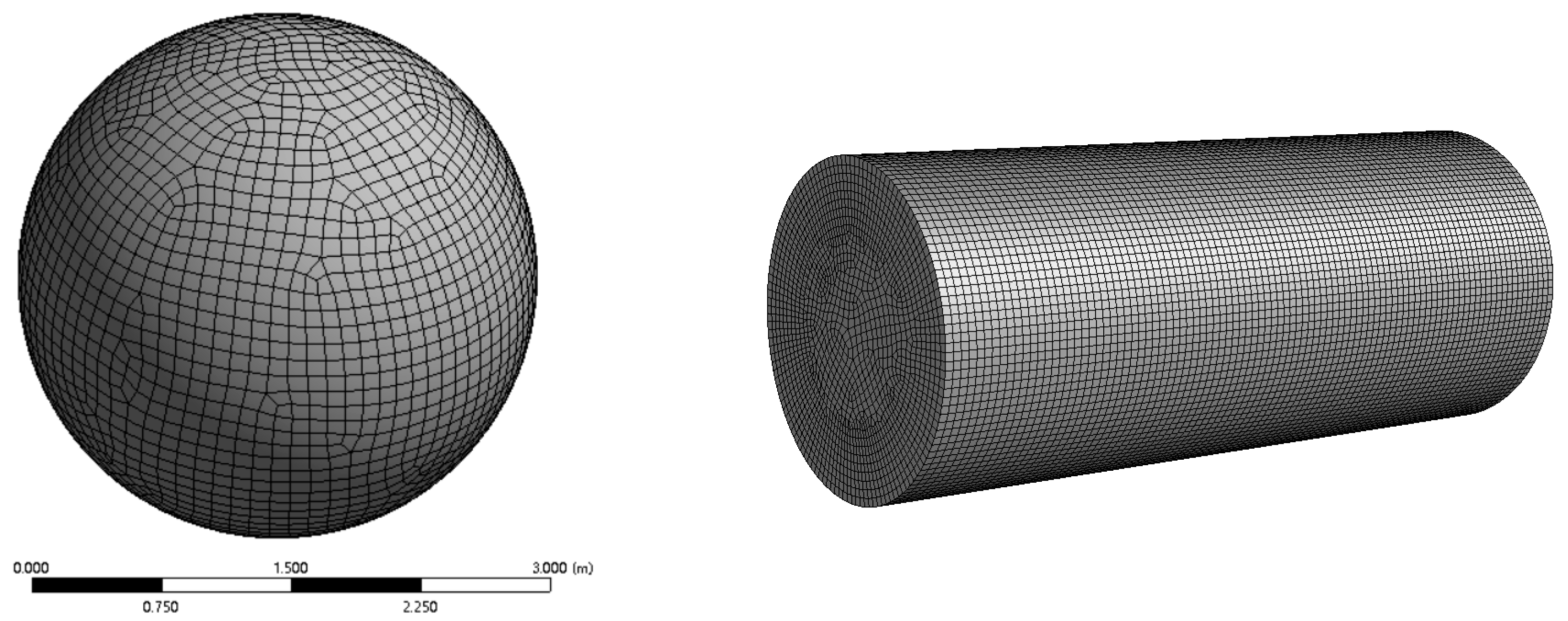
 at High Incidences

In this section, a cylindrical projectile specimen model is taken as an example, and a corresponding aerodynamic characteristics analysis model and its numerical solution method are established, which lay the foundation for the simulation of the flow field around the projectile at different speeds and angles of attack, calculation of dynamic derivatives, and subsequent sensitivity analysis. It should be noted, however, that the method described in this article can be readily applied to other projectile models.

2.1. Physical Model

As illustrated in Figure 1, the research object is a cylindrical projectile undergoing low-speed flight (about 0.2 to 0.5Ma). The center of gravity (CG) represents the projectile’s center of mass, while the moment of inertia in x , y , and z directions are 0.11 kg.m2, 0.38 kg.m2, 0.38 kg.m2, respectively. And the projectile weighs 2.4 kg. The other parameters are shown in Figure 1.

2.2. CFD Model

In this section, a CFD simulation model for the flow field around a cylinder projectile is established to study its aerodynamic characteristics under different flight states, and the basic control equations for the three-dimensional unsteady compressible flow field around a projectile are given.
In this study, the Reynolds-averaged Navier-Stokes (RANS) method is used to the time-averaged treatment of the continuous and momentum equations of flow domain as the following form,
ρ t + x i ρ u i = 0 t ρ u i + x j ρ u i u j = p ¯ x i + x j μ u i x j + u j x i 2 3 δ i j u l x l + x j ρ u i u j ¯
where the parameters subscripted “i” and “j” represent the values of the three axial directions of the inertial coordinate system, respectively; u i , u j , u l represents the Reynolds average velocity component with the average sign omitted; μ is the kinetic viscosity; and δ i j represents the Kronecker tensor component. ρ u i u j ¯ describes the Reynolds stress, which can be calculated using the eddy viscosity assumption proposed by Boussinesq [22], with the following expression:
ρ u i u j ¯ = μ t ( u i x j + u j x i ) 2 3 ( ρ k + μ t u k x k ) δ i j
k is the turbulent kinetic energy. In order to solve the unknown quantity μ t in the above equation, a variety of computational models have been developed. The ω transport equation in the k-ω two-equation model can be solved by integrating through the viscous bottom layer without additional terms, which effectively reduces the requirement of the algorithm for the near-wall mesh density, improves the computational accuracy for the region of the boundary layer separation and the internal counter pressure gradient, and is more suitable for calculating the characteristic structure of the flow field under the condition of a high angle of attack. The shear stress transport (SST) k-ω model [23] additionally considers the transfer of turbulent shear stresses in the definition of turbulent viscosity, which can accurately predict the separation flow on the smooth wall. In this paper, we adopted the SST k-ω model to simulate the turbulent flow.
ρ k t + ρ k u i x i = x j [ ( μ + μ t σ k ) k x j ] + G k Y k ρ ω t + ρ ω u i x i = x j [ ( μ + μ t σ ω ) ω x j ] + G ω Y ω
σ k = 2 , σ ω = 2 . G k represents the turbulent kinetic energy due to the average velocity gradient, Y k represents the dissipation of turbulent kinetic energy k , G ω represents the generation of the specific dissipation rate ω , and Y ω represents the dissipation of the specific dissipation rate ω . The turbulent viscosity coefficient μ t is derived from the following equation.
μ t = ρ k ω 1 max [ 1 α * , Ψ F 2 α 1 ω ]
Ψ  is the strain rate magnitude and α 1 = 0.31, and y denotes the distance from the wall, and constant α * = 1, α 0 * = 0.024, R k = 6.
Ψ = 2 Ψ ij Ψ ij , Ψ ij = 1 2 u j x i + u i x j , F 2 = t a n h ( Φ 2 2 ) , Φ 2 = max 2 k 0.09 ω y , 500 μ ρ y 2 ω , α * = α * α 0 * + R e t / R k 1 + R e t / R k

2.3. Dynamic Derivative Identification

The forced vibration method [24] has high accuracy and computational efficiency, and is a widely used method for calculating the dynamic derivative of a projectile. In this paper, the forced pitch vibration method is employed to calculate the dynamic derivative of the projectile. When the projectile is subjected to a forced vibration with a small amplitude, the dynamic derivative can be rewritten according to the assumption of the linearized aerodynamic theory of small perturbations as
C m ( t ) = C m 0 + C m α Δ α + C m α ˙ Δ α ˙ + C m q Δ q + C m q ˙ Δ q ˙ + Δ ^ ( Δ α , q )
where C m 0 represents the static pitching moment of the cylindrical projectile at an angle of attack of α 0 , C m α is the zeroth-order static derivative of the pitching moment with respect to the angle of attack, C m α ˙ is the first-order derivative of the pitching moment with respect to the angle of attack, q is the pitch angular velocity of the projectile vibration, C m q is the rotational derivative of the pitching moment with respect to the angular velocity of the pitching motion or the derivative of the damping, C m q ˙ is the first-order derivative of the pitch moment with respect to the angular velocity of the pitching motion, and Δ ^ ( Δ α , q ) represents the higher-order derivative term of Δ α and q .
Δ α = α m sin ( ω q t ) ,   Δ α ˙ = ω α m cos ( ω q t ) = q ,   Δ α ¨ = ω 2 α m sin ( ω q t ) = Δ q ˙
In the numerical calculation, a vibration period is divided into N equal parts, and the aerodynamic force of the projectile at each time step can be calculated to obtain the discrete aerodynamic data of N groups of the projectile in the whole vibration cycle, and then the combined dynamic derivative can be obtained based on Equation (8), as follows
C m α ˙ + C m q = 2 ω q α m T 0 T 0 / 2 T 0 / 2 C m ( t ) cos ( ω q t ) d t = 2 ω q α m T 0 i = 1 N 1 ( C m ( t ( i ) ) cos ( ω q t ( i ) ) + C m ( t ( i + 1 ) ) cos ( ω q t ( i + 1 ) ) 2 ) Δ t
Based on the assumption of the linearized aerodynamic theory of small perturbations, the amplitude of the forced vibration should not be too large. In this paper, the amplitude of the forced vibration is set at 1°. A new parameter, dimensionless reduction frequency k d , is introduced, which is expressed as follows:
k d = ω q L r 2 V
where L r represents the characteristic length of the cylindrical projectile. Given that the cylindrical projectile is to be flown at a large angle of attack, the total length of the projectile body is taken as L r , and V is the velocity of the free flow (refer to the standard value for the working condition setting).
According to the test results of the design index, it is considered that the process of actively adjusting the 90° pitch attitude angle of the test specimen in 70 ms is its typical flight state. The typical average angular velocity can be selected as ω t ¯ = 22.44 rad/s. When the test specimen vibrates to α ( t ) = α 0 , the following equation is achieved
t = n π ω q ( n = 0 ,   1 ,   2 ,   )
The angular velocity of the forced vibration of the prototype model is as follows:
α ˙ α = α 0 = ( 1 ) n ω q α m ( n = 0 , 1 , 2 , )
where
α ˙ α = α 0 | = ω t ¯
ω q = ω t ¯ / α m
If the amplitude of the forced vibration is 1°, then α m = π/180. Consequently, ω q = 1285.71 rad/s is derived, and the corresponding reduction frequency k d = 3.

2.4. Numerical Solution Algorithms

The overset mesh [25] technique is employed for mesh generation, and the finite volume method (FVM) is used for the solution of the three-dimensional unsteady N-S equation. The flow field and its aerodynamic characteristics distribution of the model can be calculated according to the steps illustrated in Figure 2. Prior to the calculation, the user-defined function (UDF) is employed to input the forced vibration parameters, while the overset mesh is utilized to simulate the forced vibration of the projectile throughout the calculation process. The relevant aerodynamic parameters (including the lift coefficient, drag coefficient, pitching moment coefficient, and other parameters) can be obtained by solving the control equations. Subsequently, the dynamic derivative of the projectile is further solved by combining the obtained pitching moment coefficient using the method in Section 2.3.

3. Sensitivity Analysis of Aerodynamic Characteristics

In this section, the Sobol sensitivity method based on an ARBF surrogate model [21,26,27] is adopted to analyze the influence of design parameters on the aerodynamic characteristics. The radial basis function (RBF) [26,27] uses a forward neural network model with local approximation capability to express the relationship between design variables (the radius, length, and centroid position of the cylindrical projectile, the inlet flow field velocity, and the initial angle of attack) d = [ d 1 , d 2 , , d N D ] T and output responses (the lift coefficient, drag coefficient, dynamic derivative, etc.) r ( d ) , that is
r ( d ) = r ˜ ( d ) + ε = i = 1 N s β i ϕ i ( d d S ( i ) ) + ε
where r ˜ ( d ) is the approximate value of the response r ( d ) ; ϕ i ( d d S ( i ) ) is the basis function of the design variable d ; β i ( i = 1 , , N S ) is the undetermined coefficient; ε is the error term; N D and N S are the numbers of design variables and basis functions, respectively; and · is the Euclidean norm. Commonly used basis functions include thin-plate spline functions, Gaussian functions, multi-quadric functions, etc., which determine the properties of RBF model. Taking the Gaussian function as an example
ϕ i ( d d S ( i ) ) = exp d d S ( i ) T d d S ( i ) 2 δ i 2
δ i is the normalization parameter of the Gaussian function of the i th hidden layers.
Considering that RBF model has high fitting accuracy in nonlinear problems but poor performance in linear problems, this paper adopts an ARBF model [26,27], which adds linear polynomials to the original model, that is
r ˜ ( d ) = i = 1 N s β i ϕ i ( d d S ( i ) ) + j = 1 N P b j f j ( d )
where f j ( d ) is the polynomial function of the design variable d , b j is the undetermined polynomial coefficient, ( j = 1 , , N P ) , and N P is the number of polynomial functions f j ( d ) .
By substituting the sample points d S ( i ) and their responses r S ( i ) ( i = 1 , 2 , , N S ) into Equation (17), one can obtain
r S = Φ S β + F S b + ε
where
Φ S = ϕ 1 ( d S ( 1 ) d S ( 1 ) ) ϕ 2 ( d S ( 1 ) d S ( 2 ) ) ϕ N S ( d S ( 1 ) d S ( N S ) ) ϕ 1 ( d S ( 2 ) d S ( 1 ) ) ϕ 2 ( d S ( 2 ) d S ( 2 ) ) ϕ N S ( d S ( 2 ) d S ( N S ) ) ϕ 1 ( d S ( N S ) d S ( 1 ) ) ϕ 2 ( d S ( N S ) d S ( 2 ) ) ϕ N S ( d S ( N S ) d S ( N S ) ) , r S = r S ( 1 ) r S ( 2 ) r S ( N S ) , β = β 1 β 2 β N S F S = f 1 ( d S ( 1 ) ) f 2 ( d S ( 1 ) ) f N P ( d S ( 1 ) ) f 1 ( d S ( 2 ) ) f 2 ( d S ( 2 ) ) f N P ( d S ( 2 ) ) f 1 ( d S ( N s ) ) f 2 ( d S ( N s ) ) f N P ( d S ( N s ) ) ,   b = b 1 b 2 b N P
By introducing the orthogonality condition [26,27]
i = 1 N s β i f j ( d S ( i ) ) = 0   ( j = 1 , 2 , , N P )
The following matrix form can be obtained
Φ S F S F S T O β b = r S 0
By solving the above equation, one can obtain the unknown coefficients of Equation (17). It must be pointed out that the sampling strategy of the surrogate model determines the spatial distribution of sampling points, and a reasonable number of sampling points and their spatial distribution will have a crucial impact on the accuracy of the surrogate model. In this study, the LH method [21,27] is used for obtaining the sampling point d S ( i ) = d 1 ( i ) , d 2 ( i ) , , d N D ( i ) T ( i = 1 , 2 , , N S ) , and the corresponding output response r ( d S ( i ) ) of each d S ( i ) is simulated by the method in Section 2. Furthermore, based on the cross-validation method, the average relative error (MRE) and the complex correlation coefficient ( R Square, R 2 ) are used to evaluate the accuracy of surrogate model [21,27].
Based on the surrogate model of aerodynamic characteristics, the Sobol global sensitivity method [21,27] is further applied to obtain the sensitivity of design parameters to aerodynamic characteristics. The basic principle of the Sobol method can be found in reference [21,27], which will not be elaborated here. The first-order sensitivity S ^ i and total sensitivity   S ^ i T of the input d i are solved by the following method [21,27].
S ^ i = D ^ i D ^     ,                               S ^ i T = 1 D ^ ~ i D ^
where
D ^ = 1 N S r A T r A r B ,   D ^ i = 1 N S r A T r C i f ^ 0 2 ,   D ^ ~ i = 1 N S r A T r C ~ i f ^ 0 2 ,   f ^ 0 2 = 1 N S r A T r B
r A , r B , r C i , and r C ~ i are the surrogate model’s output response to the N S × N D dimensional sampling arrays A , B , C i , and C ~ i obtained by the LH sampling method.
A = d 1 , 1 d 1 , 2 d 1 , N D d 2 , 1 d 2 , 2 d 2 , N D d N S , 1 d N S , 2 d N S , N D               B = d 1 , 1 d 1 , 2 d 1 , N D d 2 , 1 d 2 , 2 d 2 , N D d N S , 1 d N S , 2 d N S , N D C i = d 1 , 1 d 1 , 2 d 1 , i 1 d 2 , 1 d 2 , 2 d 2 , i 1 d N S , 1 d N S , 2 d N S , i 1 d 1 , i d 1 , i + 1 d 1 , k d 2 , i d 2 , i + 1 d 2 , k d N S , i d N S , i + 1 d N S , N D   C ~ i = d 1 , 1 d 1 , 2 d 1 , i 1 d 2 , 1 d 2 , 2 d 2 , i 1 d N S , 1 d N S , 2 d N S , i 1 d 1 , i d 1 , i + 1 d 1 , N D d 2 , i d 2 , i + 1 d 2 , N D d N S , i d N S , i + 1 d N S , N D

4. Numerical Simulation and Analysis

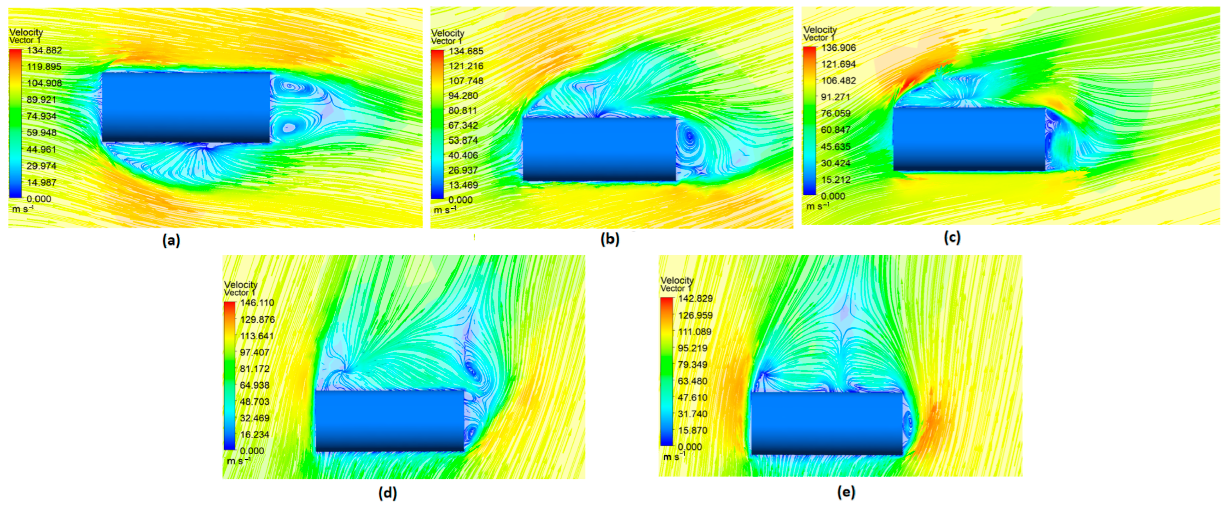
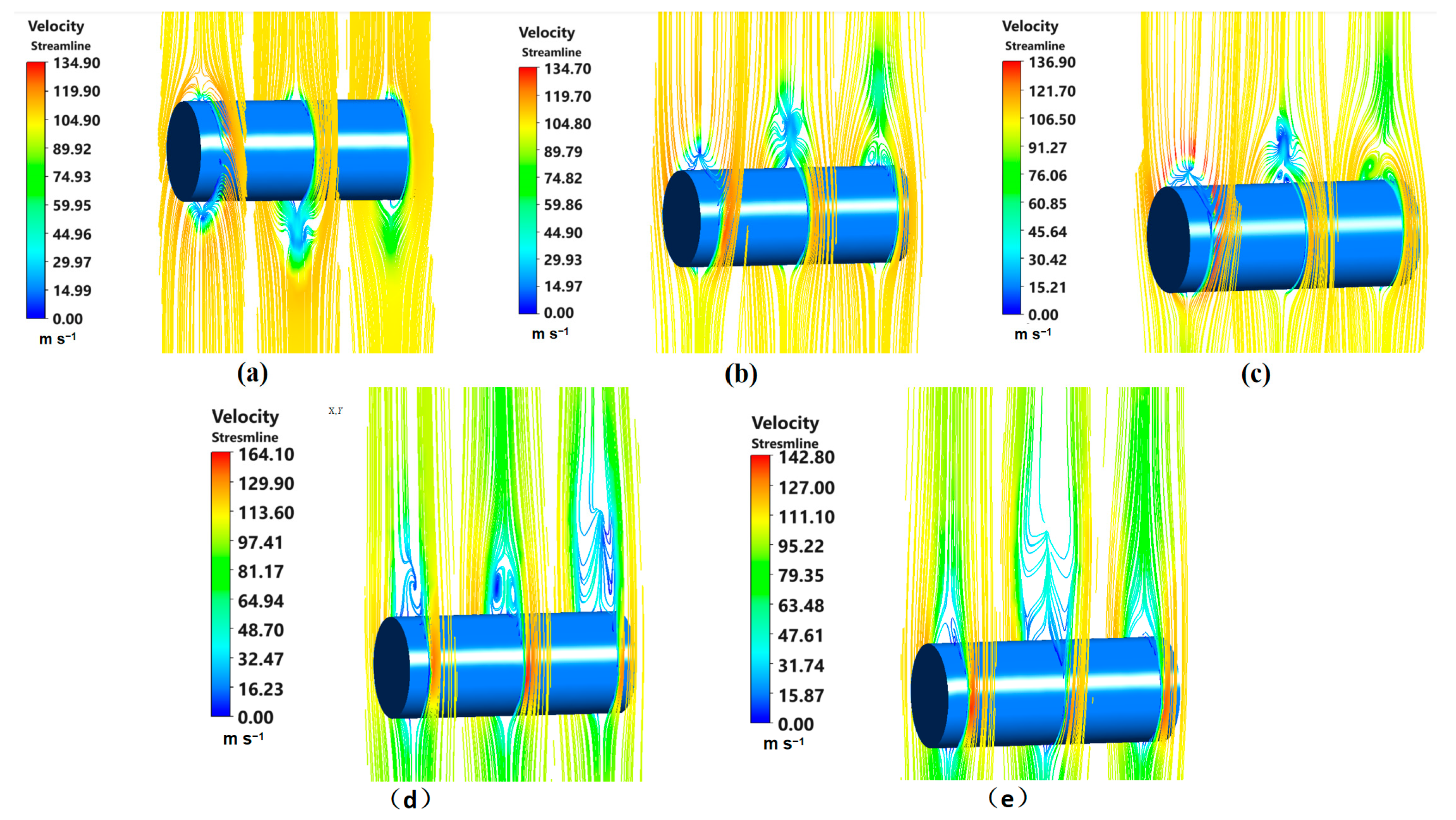
4.1. Aerodynamic Characteristics Analysis

As previously stated, the overset method is employed for meshing. In order to ensure that the distance between the first layer is less than 1 ( y + < 1), the value is set to 1.0 × 10⁻⁵ m. The structure of the model to carry out deterministic calculations is set up as follows: the diameter is 0.14 mm; the length of the projectile is 0.48 m; and the center of mass is positioned at a distance of 0.12 m from the head of the model. The basic settings are as follows: the structural mesh is used to divide the small area around the model. A component mesh is generated, and then the structural mesh is also used to divide the entire flow field calculation domain and generate a background mesh. Finally, the two sets of meshes are merged together by overlapping mesh technology, as shown in Figure 3. The overall calculation is based on the FVM, the convection terms of the governing equations are discretized according to the second order upwind scheme, and the time discretization adopts the first-order implicit format to ensure the convergence and stability of the calculation. Due to the large background mesh range, the influence of the projectile on the far-field boundary is negligible, so the far-field boundary of the computational domain is set to the pressure far-field boundary condition. This boundary can only be used for compressible gases, and the density of compressible gases must be obtained from the ideal gas equation of state. The same far-field flow velocity and flow direction are set at these boundaries in order to simulate the initial flight speed and angle of attack of the projectile. The surface of the projectile body is set to a non-slip solid wall boundary condition. The projectile is assumed to move synchronously at the same rotational speed following the rotating area. The interface between the non-rotating and rotating regions is set to the overset interface boundary condition. The initial parameters of the flow around the flow field used in the numerical simulation are presented in Table 1.
The selection of the number of meshes and the physical time step of the model has a significant impact on the simulation results, particularly in the context of unsteady calculation. Therefore, it is essential to select a reasonable time step and the number of meshes in the simulation. In order to simulate the forced vibration of the cylindrical projectile model in the dynamic derivative simulation, the component mesh can be made to vibrate with the wall of the model by overlapping mesh technology. A vibration period is divided into 200 steps, with each time step being 4.9 × 10⁻⁵ s. Table 2 shows the calculation results of the drag coefficient C d and the lift coefficient C l by using different grid numbers at inlet flow field velocity of 0.3 Ma and initial attack angle of 30°. It can be observed that, as the mesh is progressively encrypted, the aerodynamic characteristics parameters converge. Considering that the discrepancy in the calculation results for the number of grids in the three groups is minimal, the subsequent calculations are based on 110,000 grids.
On this basis, the numerical simulation method established in Section 2 is employed to compute the flow field and aerodynamic parameters of the cylinder projectile model in the range of 0°to 90°angles of attack. Figure 4 and Figure 5 illustrate the velocity distributions of the circumferential flow field in the forced vibration state of the projectile. The initial angles of attack of the model are ±1° at 0°, 10°, 30°, 60°, and 90°, respectively. As all numerical simulations are conducted in the instantaneous solver mode, all the parameters in the flow field depicted in the figures are time-averaged over the computational time period. In particular, the velocity field is displayed on the symmetry plane of the projectile in Figure 4. The velocity distribution of the circumferential flow is displayed on the front, middle, and tail sections of the model in Figure 5. Since the dynamic derivative calculation is set according to the forced vibration of ±1°, it can be observed in the figures that the fluid separation phenomenon begins to appear in the front and middle part of the model when the initial angle of attack is 0°. Upon increasing the initial angle of attack to 10°, the fluid separation phenomenon has already appeared in the head, middle, and tail sections of the model. A pronounced asymmetric counter-rotating vortex is evident in the middle of the model in the streamline diagram. This pair of counter-rotating vortices has not yet fully detached from the wall under the angle of attack, and the flow field is essentially symmetrical with respect to the mid-vertical plane of the model. As the initial angle of attack continues to increase to 30°, counter-rotating vortices also begin to appear in the head and tail of the model. Meanwhile, the counter-rotating vortex pairs on the leeward side at the center of the model gradually detach themselves from the wall, exhibiting an asymmetric phenomenon. When the angle of attack increases to 60°, the fluid on the leeward side of the model is completely separated, the vortex on the leeward side of the model head also exhibits an asymmetric phenomenon, and the vortex structures in the middle and rear parts of the model all show an alternating shedding phenomenon. As the angle of attack increases to 90°, the alternating vortex shedding phenomenon is observed on all of the model leeward surfaces. Additionally, a wide range of vortex shedding phenomena is observed in the middle of the model leeward surfaces, which even affects the formation of asymmetric vortices in the rear. These series of changes demonstrate that with the increase in the angle of attack, the counter-rotating vortex pairs on the leeward side of the model gradually detach from the wall at the tail of the model, resulting in an asymmetric structure due to the mutual extrusion of the two vortices.
The aerodynamic coefficients in the pitch plane with different initial angles of attack are given in Figure 6. The results in Figure 6 are the time-averaged values obtained after a certain time of steady computation. Figure 6a illustrates that the lift coefficient of the model initially increases with the increasing angle of attack, reaching a maximum at 60°. Thereafter, the lift coefficient starts to decrease with further increases in the angle of attack. This is due to the fact that, as the angle of attack increases, the normal force on the model gradually increases. The lift force is mainly composed of the component of the normal force perpendicular to the direction of the incoming velocity. In the range of angles of attack from 0° to 60°, the increase in both the normal force and the angle of attack is favorable to the increase in this component. However, when the angle of attack is greater than 60°, the increase in the angle of attack is not favorable to the increase in this component. Figure 6b illustrates that the lift-to-drag ratio increases with the increase in the angle of attack from 0° to 30°. However, when the angle of attack is larger than 30°, the resistance of the basic model still shows an increasing trend, but the increase in the lift force becomes smaller, resulting in a slight decrease in the lift-to-drag ratio. Subsequently, when the angle of attack exceeds 60°, the phenomenon of fluid separation is observed in the majority of areas on the leeward side of the model. At this point, the change in the angle of attack will not cause any significant impact on the pressure difference between the windward and leeward surfaces of the model, and the lift-to-drag ratio shows a declining trend. The evolution of the pitching moment coefficient in relation to the angle of attack is shown in Figure 6c. The absolute value of the pitching moment coefficient is relatively small. The pitching moment coefficient is positive at small angles of attack, indicating that the basic model is in a static unstable state at these angles of attack. The negative value of this coefficient within the calculated angle of attack variation indicates that the model is in a static stable state. Its absolute value firstly increases with the increase in the angle of attack but starts to fluctuate around the angle of attack near 60°. The fluctuations observed in the pitching moment coefficient can be attributed to the gradual expansion of the separation zone on the leeward side of the front of the model towards the center and rear part.
Table 3 presents the results of the dynamic derivatives of the pitching motion for Inlet flow field velocity = 0.3 Ma and the initial angle of attraction α0 = 0°, 10°, 30°, 60°, and 90°. It can be seen that the pitching combined dynamic derivatives for each state are negative. This indicates that the pitching damping moments applied to the model during the forced vibration are always in the opposite direction of the rotational velocity. This inhibits the pitching rotation of the model, and the smaller the value of the pitching combined derivatives, the greater the inhibition of the rotation. The combined pitching derivative of the model fluctuates in a small range as the initial angle of attack increases. The maximum value is observed at an initial angle of attack of 30°, which means that the model’s dynamic stability is the worst at this point. Conversely, the minimum value is observed at an initial angle of attack of 10° and then 90°, which indicates that the model’s dynamic stability is the best at these points. Although there are some discrepancies in the calculated aerodynamic parameters of the cylindrical projectile model at large angles of attack, the magnitude of the discrepancy is within the acceptable range.

4.2. Results of Sensitivity Analysis

In this section, the global sensitivity analysis is conducted to assess the effect of design parameters on the aerodynamic characteristics of the projectile. The first step is to determine the input design parameters of the system and their distributions. The simulation and tests show that the main factors affecting the aerodynamic characteristics include the angle of attack of the vehicle, the incoming velocity, the position of the center of mass, the diameter of the projectile, the length, and so on [9]. In this study, the design parameters and their distributions are chosen, as shown in Table 4.
A total of 50 groups of design sampling points are selected within the given design space, and the corresponding aerodynamic characteristics (lift coefficient, drag coefficient, pitch moment coefficient, and combined dynamic derivatives) are obtained through CFD simulations proposed in Section 2. Subsequently, the ARBF models for the lift coefficient, drag coefficient, pitch moment coefficient, and combined dynamic derivatives can be constructed. Based on the ARBF models, the Sobol method is employed to determine the first-order and the total sensitivity coefficients, as shown in Section 3.
The first-order and total global sensitivities of the design parameters on the aerodynamic characteristics while the angle of attack is 10° are shown in Table 5 and Figure 7. Comparison of the two graphs in Figure 7 clearly shows that the centroid position has the greatest effect on the lift coefficient and drag coefficient, while the incoming velocity has the greatest effect on the pitch moment coefficient and combined dynamic derivatives, when the angle of attack is 10°. The variation of the total sensitivity of the pitch moment coefficient with the different angles of attack are shown in Figure 8. From Figure 8, it can be seen that, at different angles of attack, the effect of the four design parameters on the pitch moment coefficient varies. In order to ensure the dynamic performance of the different angle of attack maneuvering, the influence of these four parameters should be fully and comprehensively considered in practical design.

5. Conclusions

In this study, a comprehensive analysis of the aerodynamic characteristics and the combined dynamic derivative of a typical cylindrical projectile are presented by using the FVM combined with the SST k-ω turbulence model. On this basis, the improved efficient Sobol global sensitivity analysis method based on the ARBF surrogate model and LH sampling is used to analyze the sensitivity of design parameters on the cylindrical projectile’s aerodynamic characteristics. The conclusion is as follows:
(1)
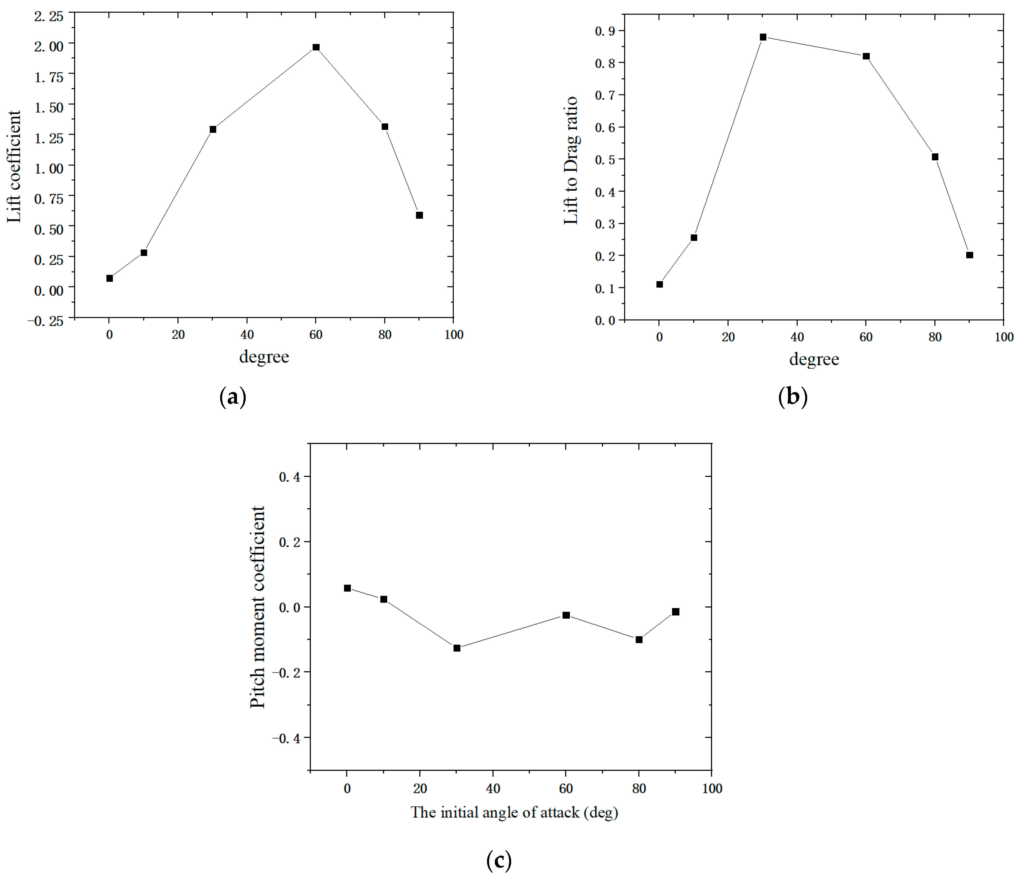
For the cylindrical projectile model, the lift-to-drag ratio increases with the increase in the angle of attack from 0° to 30°, and then the lift-to-drag ratio tends to decrease when the angle of attack exceeds 60°; the absolute value of the pitching moment coefficient firstly increases with the increase in the angle of attack, and the static stability of the cylindrical projectile model becomes better after the angle of attack is 60°; with the increase in the angle of attack, the dynamic derivative of the cylindrical projectile model fluctuates in a small range, and the maximum value occurs when the angle of attack is 30°, which means that the dynamic stability of the model is the worst at this time.
(2)
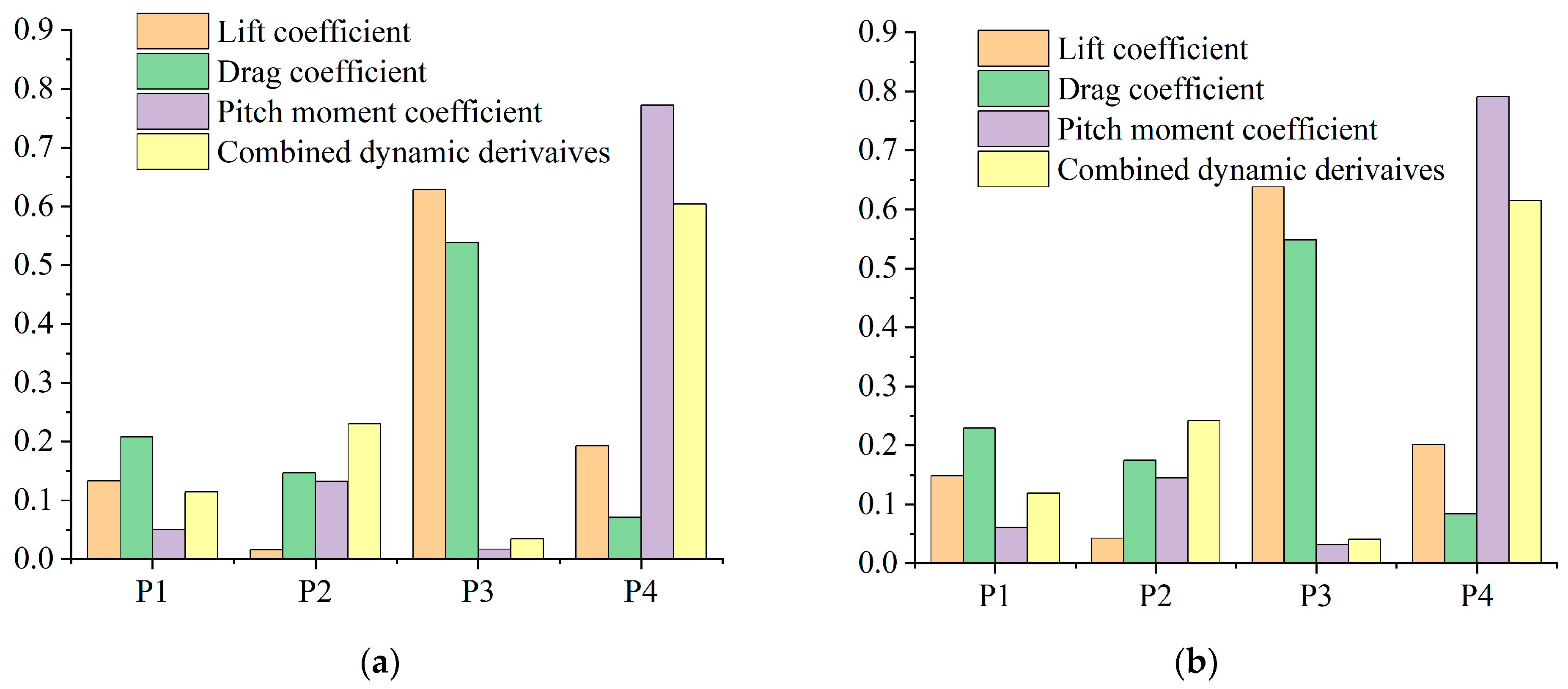
The centroid position has the greatest effect on the lift coefficient and drag coefficient, while the incoming velocity has the greatest effect on the pitch moment coefficient and combined dynamic derivatives, when the angle of attack is 10°; at different angles of attack, the effect of the four design parameters on the aerodynamic characteristics varies. In order to ensure the dynamic performance of the different angle of attack maneuvering, the influence of these four parameters should be fully and comprehensively considered in practical design.
This study provides a typical case for the analysis and design of related engineering systems’ aerodynamic characteristics, providing important theoretical and engineering value.

Author Contributions

Conceptualization, S.J., L.T. and H.W.; methodology, S.J., L.T. and W.R.; software, S.J., L.T. and X.W.; validation, L.T.; formal analysis, L.T.; investigation, S.J.; resources, S.J., L.T. and H.W.; data curation, L.T.; writing—original draft preparation, S.J. and L.T.; writing—review and editing, S.J., and L.T.; supervision, W.R. and H.W.; project administration, S.J. and H.W.; funding acquisition, S.J. All authors have read and agreed to the published version of the manuscript.

Funding

This research received no external funding.

Institutional Review Board Statement

Not applicable.

Informed Consent Statement

Not applicable.

Data Availability Statement

Data sharing not applicable, as this article describes a method of dynamics modeling and analysis, and the data supporting this study have been made available within the article.

Conflicts of Interest

The authors declared that they have no conflicts of interest regarding this work. We do not have any commercial or associative interest that represents a conflict of interest in connection with the work submitted. The work described has not been submitted elsewhere for publication, in whole or in part, and all the authors listed have approved the manuscript that is enclosed.

References

  1. Hankey, W.L.; Graham, J.E.; Shang, J.S. Navier-Stokes solution of a slender body of revolution at incidence. AIAA J. 1982, 20, 776–781. [Google Scholar] [CrossRef]
  2. Degani, D.; Marcus, S.W. Thin vs full Navier-Stokes computation for high-angle-of-attack aerodynamics. AIAA J. 1996, 35, 565–567. [Google Scholar] [CrossRef]
  3. Yang, Y.J.; Cui, E.I.; Zhou, W.J. Numerical studies about a symmetric vortex flow around a slender body at high incidence. Chin. J. Theor. Appl. Mech. 2004, 36, 1–8. [Google Scholar]
  4. Liu, X.M.; Fu, S. Numerical simulation of separated flows over slender body at high-angle-of-attack with k-ε model conforming realizability. Chin. J. Comput. Mech. 2006, 23, 275–279. [Google Scholar]
  5. Zhang, H.X. Structural Analysis of Separated Flows and Vortex Motion; National Defense Industry Press: Beijing, China, 2005. [Google Scholar]
  6. Tian, S.L. Research on Overlapping Grid Algorithm Based on Unstructured Grid Method. Doctoral Dissertation, Nanjing University of Aeronautics and Astronautics, Nanjing, China, 2008. [Google Scholar]
  7. Zhu, Y.; Yuan, H.; Lee, C. Experimental investigations of the initial growth of flow asymmetries over a slender body of revolution at high angles of attack. Phys. Fluids 2015, 27, 084103. [Google Scholar] [CrossRef]
  8. Qi, Z.; Wang, Y.; Bai, H.; Sha, Y.; Li, Q. Effects of micro perturbations on the asymmetric vortices over a blunt-nose slender body at a high angle of attack. Eur. J. Mech./B Fluids 2018, 68, 211–218. [Google Scholar] [CrossRef]
  9. Wang, X.; Wang, Z.W.; Ruan, W.J. Analysis on flowfield and aerodynamic characteristics of escort free-flight decoy with asymmetrical tail at high incidences. J. Ordnance Equip. Eng. 2021, 42, 55–60+82. [Google Scholar]
  10. Ramberg, S.E. The effects of yaw and finite length upon the vortex wakes of stationary and vibrating circular cylinders. J. Fluid Mech. 1983, 128, 81–107. [Google Scholar] [CrossRef]
  11. Zdravkovich, M.M. Flow around Circular Cylinders: Volume 2: Applications; Oxford University Press: Oxford, UK, 1997. [Google Scholar]
  12. Silva-Leon, J.; Cioncolini, A. Effect of inclination on vortex shedding frequency behind a bent cylinder: An experimental study. Fluids 2019, 4, 100. [Google Scholar] [CrossRef]
  13. Alam, M.M.; Abdelhamid, T.; Sohankar, A. Effect of cylinder corner radius and attack angle on heat transfer and flow topology. Int. J. Mech. Sci. 2020, 175, 105566. [Google Scholar] [CrossRef]
  14. Hoang, N.T.; Rediniotis, O.K.; Telionis, D.P. Symmetric and asymmetric separation patterns over a hemisphere cylinder at low reynolds numbers and high incidences. J. Fluids Struct. 1997, 11, 793–817. [Google Scholar] [CrossRef]
  15. Nabi, S.; Ahanger, M.A.; Dar, A.Q. Investigating the potential of Morris algorithm for improving the computational constraints of global sensitivity analysis. Environ. Sci. Pollut. Res. 2021, 28, 60900–60912. [Google Scholar] [CrossRef] [PubMed]
  16. Yu, Y.R.; Li, C.; Yao, L.Q. Global sensitivity analysis on vertical model of railway vehicle based on extended Fourier amplitude sensitivity test. J. Vib. Shock. 2014, 33, 77–81. [Google Scholar]
  17. Sobol, I.M. Sensitivity estimates for nonlinear mathematical models. Math. Model. Comput. Exp. 1993, 1, 112–118. [Google Scholar]
  18. Antoniadis, A.; Lambert-Lacroix, S.; Poggi, J.M. Random forests for global sensitivity analysis: A selective review. Reliab. Eng. Syst. Saf. 2021, 206, 107312. [Google Scholar] [CrossRef]
  19. Du, W.Q.; Li, S.X.; Luo, Y.X. Implementation of Sobol’s sensitivity analysis to cyclic plasticity model with parameter uncertainty. Int. J. Fatigue 2021, 155, 106578. [Google Scholar] [CrossRef]
  20. Liu, Q.; Feng, B.W.; Liu, Z.Y.; Hao, Z.; Zhang, H. The improvement of Sobol’ sensitivity analysis method. In Proceedings of the 2015 First International Conference on Reliability Systems Engineering (ICRSE), Beijing, China, 21–23 October 2015. [Google Scholar]
  21. Tao, L.; Xie, Y.; Hu, C. Efficient sensitivity analysis for enhanced heat transfer performance of heat sink with swirl flow structure under one-side heating. Energies 2022, 15, 7342. [Google Scholar] [CrossRef]
  22. Boussinesq, J. Essay on the Theory of Water Currents. In Memoirs Presented by Various Scholars to the Academy of Sciences; Series 2; Institute of France: Paris, France, 1877; Volume 23, pp. 46–50. [Google Scholar]
  23. Menter, F.R. Two-equation eddy-viscosity turbulence models for engineering applications. AIAA J. 1994, 32, 1598–1605. [Google Scholar] [CrossRef]
  24. Allen, J.; Ghoreyshi, M. Forced motions design for aerodynamic identification and modeling of a generic missile configuration. Aerosp. Sci. Technol. 2018, 77, 742–754. [Google Scholar] [CrossRef]
  25. Liu, J.; Xu, C.G.; Bai, X.Z. Finite Volume Method and Unstructured Moving Grids; Science Press: Beijing, China, 2016. [Google Scholar]
  26. Krishnamurthy, T. Response surface approximation with augmented and compactly supported radial basis functions. In Proceedings of the 44th AIAA/ASME/ASCE/AHS/ASC Structures, Structural Dynamics, and Materials Conference, Norfolk, VA, USA, 7–10 April 2003. [Google Scholar]
  27. Ye, P.C. Research on Surrogate Modeling Techniques and Applied to Shape Design of Autonomous Underwater Glider. Doctoral Dissertation, Northwestern Polytechnical University, Xi’an, China, 2017. [Google Scholar]
Figure 1. Basic model of the cylindrical projectile.
Applsci 14 06683 g001
Figure 2. Schematic diagram of the aerodynamic characteristics simulation.
Applsci 14 06683 g002
Figure 3. Meshing of the external flow field zone and surface of the projectile.
Applsci 14 06683 g003
Figure 4. Velocity vector diagram and its streamline distribution diagram on the symmetry plane with different angles of attack. (a) The attack angles of 0°; (b) The attack angles of 10°; (c) The attack angles of 30°; (d) The attack angles of 60°; (e) The attack angles of 90°.
Applsci 14 06683 g004
Figure 5. Velocity distribution of circumferential flow field with different angles of attack. (a) The attack angles of 0°; (b) The attack angles of 10°; (c) The attack angles of 30°; (d) The attack angles of 60°; (e)the attack angles of 90°.
Applsci 14 06683 g005
Figure 6. Aerodynamic coefficients in the pitch plane at different initial angles of attack. (a) The lift coefficient; (b) The Lift-to-drag ratio; (c) The Pitch moment coefficient.
Applsci 14 06683 g006
Figure 7. Histogram of sensitivity analysis results at the angle of attack at 10°. (a) The first-order sensitivity; (b) The total sensitivity.
Applsci 14 06683 g007
Figure 8. Histogram of total sensitivity analysis results of the pitch moment coefficient with the different angles of attack.
Applsci 14 06683 g008
Table 1. Parameters of the flow field around the model under initial certain conditions.
ParameterMach (Ma)Pressure (Pa)Temperature (K)Reduction Frequency k d Amplitude α m /degRoll Angle ϕ /deg
Value0.31002883190
Table 2. Verification of grid independence of aerodynamic parameters at an angle of attack of 30°.
Grid NumberNumber of GridsNumber of NodesLift Coefficient C l Drag Coefficient C d
187,39426,1641.09991.3036
293,11827,1751.04911.2873
3117,36531,5391.02881.2734
Table 3. Combined dynamic derivatives of pitch with different initial angle of attack ( C m α ˙ + C m q ) .
Initial Angles of Attack10°30°60°80°90°
Value−0.047−0.057−0.031−0.046−0.049−0.057
Table 4. Parameters for sensitivity analysis.
Serial NumberParametersValue Range
P1Radius (m)0.05–0.2
P2Length (m)0.48–0.68
P3Centroid position (m)0.1–0.45
P4Inlet flow field velocity (Ma)0.1–0.5
Table 5. Sensitivity indices of different design parameters at the angle of attack at 10°.
ParametersP1/RadiusP2/LengthP3/Centroid PositionP4/Inlet Flow Field Velocity
First-Order SensitivityLift coefficient0.1330.0160.6280.193
Drag coefficient0.2080.1470.5380.071
Pitch moment coefficient0.0500.1320.0170.772
Combined dynamic derivatives0.1140.2300.0370.604
Total SensitivityLift coefficient0.1480.0430.6380.201
Drag coefficient0.2290.1750.5490.084
Pitch moment coefficient0.0610.1450.0320.791
Combined dynamic derivatives0.1190.2420.0410.615
Disclaimer/Publisher’s Note: The statements, opinions and data contained in all publications are solely those of the individual author(s) and contributor(s) and not of MDPI and/or the editor(s). MDPI and/or the editor(s) disclaim responsibility for any injury to people or property resulting from any ideas, methods, instructions or products referred to in the content.

