Article

Deformation Characteristics and Response Factors of Rock Bolt Body in Roadway with Layered Composite Roof

School of Energy & Mining Engineering, China University of Mining and Technology-Beijing, Beijing 100083, China
*
Author to whom correspondence should be addressed.
Appl. Sci. 2024, 14(15), 6694; https://doi.org/10.3390/app14156694
Submission received: 4 July 2024 / Revised: 24 July 2024 / Accepted: 29 July 2024 / Published: 31 July 2024

Abstract

:
Layered composite roofs are characterized by developed bedding fissures, resulting in severe deformation and damage of rock bolts at the top of the roadway, as well as a poor roadway support effect. Increasing pretension force is an effective way to enhance the stiffness of the rock bolt support system. To clarify the influence and mechanism of the pretension force on the support effect of rock bolts in the layered roof, a roadway model of the layered roof was established using the interface unit of FLAC3D, and the simulation rock bolts were constructed using the pile unit, which can simulate the mechanical behaviors of rock bolts, such as tension, shear, bending, fracture, and anchor failure, and the pretension force was applied. On this basis, the deformation and failure characteristics and influencing factors of rock bolts in the layered roadway roof under different surrounding rock conditions were simulated and analyzed. The research shows the following: ① Field measurements showed minor shear deformation in the rock bolts at the center of the roadway roof, with lateral displacements of 5.7 cm and 5.3 cm. Significant shear deformation occurred in the rock bolts at the roof corners, with lateral displacements of 18.2 cm and 17.6 cm. ② Simulations of rock bolt deformation characteristics matched the field measurements closely, confirming the reliability of the simulation method, parameter selection, and calculation sequence. ③ The primary factors affecting rock bolt deformation are the structural plane strength and surrounding rock strength. Rock bolts are most susceptible to lateral displacement when the structural plane strength is low, the strength difference between rock layers is large, and the weaker layer is below the structural plane. The presented research can provide a reference for the instability mechanism and support treatment of the layered composite roof roadway.

1. Introduction

Rock bolt support, as an economical and effective active support method, has been widely applied in engineering supports, such as tunnels, slopes, water conservancy and hydropower, and underground mines [1,2]. Rock bolt support is the main support form in Chinese coal mine roadways. In the excavation of about 8000 km of coal mine roadways every year, 80% adopt rock bolt support [3]. The factors that affect the stability of the roadway surrounding rock and the effect of rock bolt support usually include water corrosion [4], the width of the coal pillar reserved [5], as well as the diameter and angle of the rock bolt installation, rock strength, grouting material, rock bolt material, drilling diameter, pre-tightening force of the rock bolt, normal stress, surface roughness of the joint, expansion angle of the joint, etc. [6,7]. Many scholars at home and abroad have studied the mechanism and failure mechanism of rock bolts under different conditions through three aspects: laboratory tests, numerical simulations, and theoretical analyses.
In terms of laboratory tests, Nourizadeh et al. [8] studied the influence of the intermediate principal stress on the strength characteristics of rock bolts through true triaxial tests. The results show that as the confining pressure gradually increases from zero, the behavior of rock bolts before failure changes from linear to nonlinear. Entezam et al. [9] revealed the influence of adding fly ash in grouting on the axial bearing capacity of fully grouted rock bolts through rock bolt pull-out tests and uniaxial compression tests. The results show that after the addition of fly ash, the axial bearing capacity of rock bolts can be effectively improved. Yu et al. [10] applied confining pressure and pull-out load in indoor tests and conducted tests on rock bolts using ultrasonic guided waves. The propagation law of ultrasonic guided waves and the bonding quality of rock bolts under the action of pull-out load and confining pressure were studied. Jodeiri Shokri et al. [11] revealed the influence of the restraint diameter on the axial bearing capacity of rock bolts through grouting solidification and rock bolt pull-out tests. The results show that increasing the restraint diameter, the bearing capacity of rock bolts increases by approximately 32% and 45% on the 7th and 28th days, respectively. Nourizadeh et al. [12] prepared a rock bolt heating pull-out test device and studied the mechanical properties of resin rock bolts under high-temperature conditions. The results show that when the ambient temperature reaches 75 °C and 150 °C, the bonding capacity of resin rock bolts decreases by 6.6% and 31.3%, respectively.
In the field of numerical simulation, He et al. [13,14] conducted a large number of anchorage shear laboratory tests on 2G-NPR rock bolts. A three-dimensional refined numerical simulation method considering the elastic–plastic mechanical behavior of rock mass, the tensile–shear fracture criterion of rock bolts, and the damage and deterioration of the grouting body was proposed. Tahmasebinia et al. [15,16] analyzed the influence of different parameters of the anchor bolt on its ultimate bearing capacity through the finite element analysis software ABAQUS/Explicit. It is indicated that in the environment where the roadway is in a layered composite roof and under impact ground pressure, flexible bolts can play an important role due to their strong ability to resist dynamic loads. Chen et al. [17] used the PFC simulation method to study the macroscopic shear behavior and microscopic failure characteristics of a single rock bolt under different types of rock joints. Jiang et al. [18], based on the failure theory of rock bolts, modified the mechanical model of the pile element in the FLAC3D program and revealed the distribution and evolution characteristics of the axial force and shear resistance of rock bolts.
From the perspective of theoretical analysis, Zhan et al. [19] proposed an effective characterization method for the stress concentration of the surrounding rock in coal mine roadways, replacing the traditional measurement method of the stress of the surrounding rock in the roadway. Kong et al. [20] studied the influence of the loss of the pre-tightening force of high-strength rock bolts on the basic mechanical properties of the structure. The results show that the loss of the pre-tightening force of high-strength rock bolts reduces the connection strength and structural stiffness, but the influence on the ultimate bearing capacity of the structure is very limited. Yi et al. [21] pointed out that the hardness of the surrounding rock of the roadway and the integrity of the rock mass are important factors affecting the anchoring performance of rock bolts in jointed rock. Therefore, a rock bolt pull-out test was designed, and the two influencing factors of rock hardness and integrity were comprehensively considered. The calculation formulas for the ultimate pull-out load and ultimate displacement of mortar rock bolts in jointed rock were established and proposed. Peng [22] introduced the underground rock bolt support mode in American coal mines, indicating that if the roof strata are weak, especially affected by weathering, the rock beams between the rock bolts will be damaged and fall off over time.
Engineering rock masses are often affected by frequent geological tectonic movements and complex stress fields, often resulting in many weak structural planes, such as fractures, joints, and faults. These weak structural planes seriously damage the integrity and continuity of the surrounding rock of the roadway [23]. Therefore, most coal mine roadways belong to layered composite roof roadways. The layered composite roof generally refers to the roof rock mass being several layers of heterogeneous soft and hard interlayered strata, which often contain weak interlayers such as thin coal and generally have poor mechanical properties and interlayer cementation. Therefore, the surrounding rock of the roadway roof is prone to large deformations and failures, such as dislocation and separation along the weak structural planes, which is also the decisive factor leading to the failure of rock bolt support [24]. Both Yang and Ma et al. [25,26] indicated that the composite roof poses a great threat to the safe production of the working face and the stability of the surrounding rock of the roadway. According to relevant data statistics, more than one-third of the coal roadway roofs in China belong to the layered composite roof, and the layered composite roof roadways have typical characteristics such as large surrounding rock deformation, sudden roof collapse, and great support difficulty during the mining process, which greatly weakens the anchoring effect of roadway rock bolts. Due to the significant difference in the mechanical properties of the weak interlayers, the deformation of the rock bolts is very serious, thereby causing difficulties in roadway support and severely restricting the safe production of the mine. According to statistics, the number of accidents caused by composite-roof-type roadways in the coal mine production process accounts for 2/3 of all roadway roof collapse accidents, but at present, scholars at home and abroad have conducted less research on the deformation of rock bolts and its influencing factors in the layered composite-roof-type roadways. In response to the above problems, in this paper, a “break-tension-suture” method for applying the pretension force of the pile unit simulation rock bolt was put forward. The weak surface of the layered composite roof structure was simulated through the use of the interface. A reasonable calculation sequence of the stress field of the surrounding rock before and after the rock bolt was devised. On this basis, by employing the aforesaid simulation method, the deformation and failure characteristics of the anchor bolts in the roadway with a layered composite roof and their influencing factors under different surrounding rock conditions were analyzed.
This paper selected six rock bolts from typical layered composite roof roadways and analyzed their force and deformation characteristics. Through FLAC3D, a unified model of rock bolt deformation and stress evolution in the layered composite roof roadway was constructed. The force and deformation characteristics of the on-site rock bolts were inversely simulated. The influence of the strength of the surrounding rock and the structural plane on the shear and bending deformation of the rock bolts was further simulated and analyzed.

2. Field Sampling Analysis of Roadway Rock Bolts

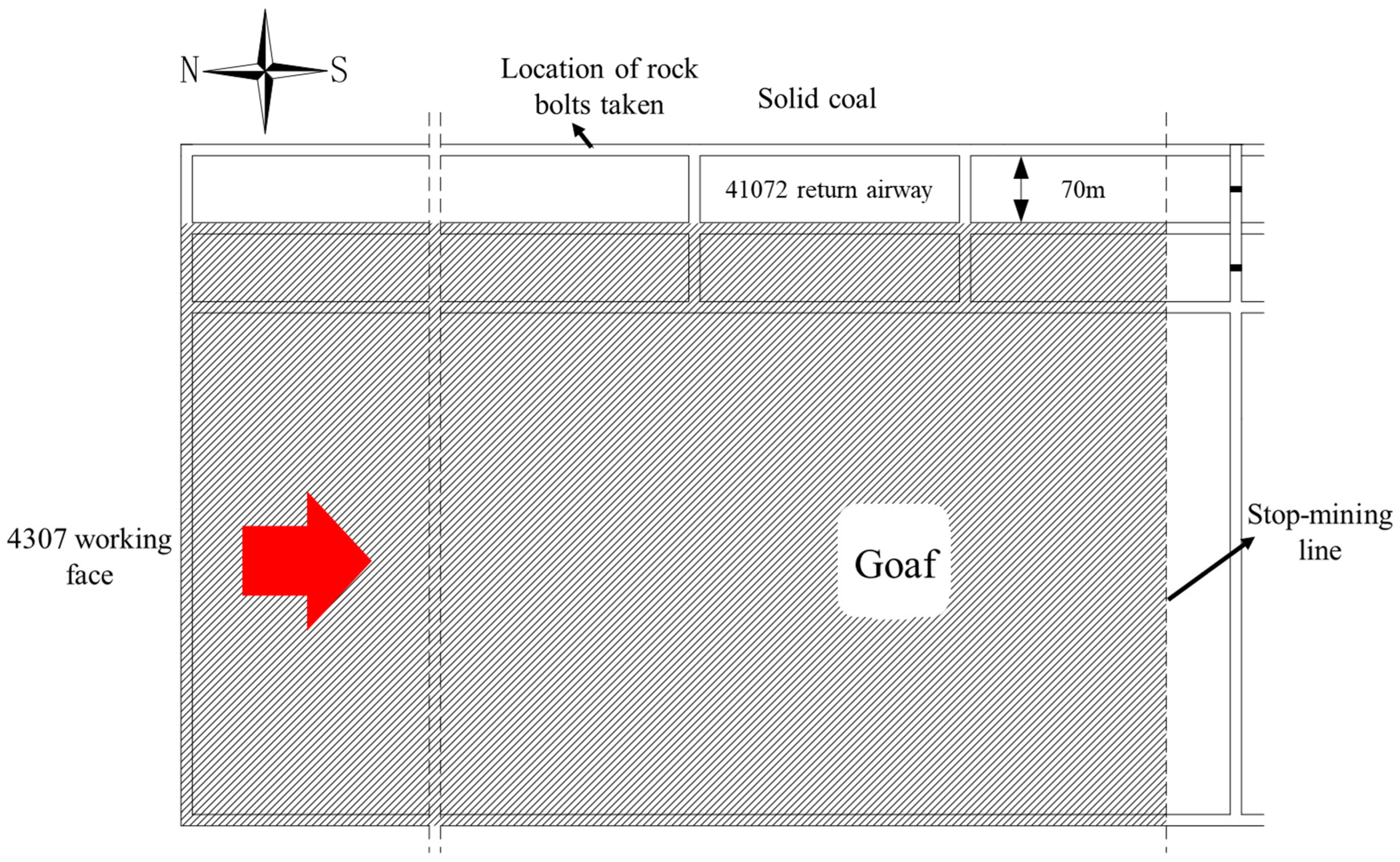
2.1. Engineering Background

The coal seam mined at the 41072 working face of Changping Mine is the main mined 3# coal seam of the mine. The average burial depth is 500 m. The average dip angle is 6°, belonging to the nearly horizontal coal seam. The thickness of the coal seam ranges from 4.60 to 6.83 m, with an average thickness of 5.86 m. The length of the 41072 working face is 300 m, and the designed mining height is 5.86 m. Fully mechanized mining with full-seam extraction is adopted. The average advancing speed is 2.54 m/d. The treatment method of the goaf is the total caving method. Furthermore, according to the geological data of the mine, the hydrogeological conditions of the mine are simple: the coal seam is not prone to spontaneous combustion, and the coal dust has no explosiveness. The mine belongs to a low-impact tendency mine. However, due to the large mining height and burial depth of the working face, the periodic weighting of the mine is intense. The 41072 roadway in Changping Mine was originally the return airway of the 4307 working face. After the mining of 4307 was completed, the roadway was retained to serve the 4107 working face. The layout of roadway 41072 is shown in Figure 1. The 4107 working face mainly mines the 3# coal seam, with an average thickness of 5.75 m. The average uniaxial compressive strength of the coal body is distributed between 12.8 and 15.4 MPa. The immediate roof is sandy mudstone, with a thickness of 1.57 m. The fissures are developed, the rock is soft, and the strength is mainly concentrated between 27.6 and 32.6 MPa. The main roof is medium sandstone, with a thickness of 9.26 m. The rock is hard, the strength is between 70.0 and 80.0 MPa, and the uniaxial compressive strength is large. The immediate floor is sandy mudstone, with a thickness of 6.89 m. The strength is between 25.8 and 34.9 MPa, and the uniaxial compressive strength is small. The old floor is sandstone, with a thickness of 2.20 m, hard texture, and an average strength of 70.5 MPa.
The measurement results of in situ stress in the fourth panel area of Changping Mine show that the maximum σH is 10.81 MPa and the minimum is 8.85 MPa. In terms of magnitude, the magnitude of the in situ stress field in the fourth panel area is moderately low. The lateral pressure coefficient σHV is greater than 1. The in situ stress in the panel area is dominated by horizontal stress and belongs to the type of tectonic stress field. The maximum horizontal principal stress is generally in the north-east-east direction. The geological and hydrological conditions in the fourth panel area are relatively simple.
The 41072 roadway is excavated along the floor, with 2 m thick top coal at the top and a layer of gangue 500 mm below the immediate roof. The 41072 roadway adopts the combined support of rock bolts and cables. The rock bolts have a diameter of 22 mm and a length of 2400 mm. The steel grade is BHRB500, where ‘B’ is the abbreviation of the manufacturer, ‘HRB’ is the abbreviation of ‘Hot Rolled Ribbed Bars’, and ‘500’ indicates a yield strength of 500 MPa. The thread at the tail of the bolt is M24, where ‘M’ represents the common thread and ‘24’ indicates that the major diameter (nominal diameter) of the thread is 24 mm. It is often used for fastening mechanical connection components. There are six rock bolts in each row, with a row spacing of 900 mm and a spacing of 1000 mm. The top corner rock bolts are 300 mm away from the roadway side and are all set perpendicularly to the roof. The resin-extended anchorage uses two anchoring agents, one with a specification of MSK2335 and the other with a specification of MSZ2360. Among them, ‘MS’ represents ‘Resin Anchoring Agent’, ‘23’ is the diameter of the anchoring agent, and both are 23 mm. The length of the anchoring agent is denoted as ‘60’, which is 350 mm and 600 mm, respectively. The drilling diameter is 30 mm, and the theoretical anchoring length is 1208 mm. The roadway support of 41072 is shown in Figure 2.
According to the on-site borehole peeping results of the surrounding rock, above the coal seam roof of the 41072 roadway in Changping Mine is a typical layered composite soft rock roof of mudstone and sandy mudstone. The inner layered joints and fissures of this mudstone or sandy mudstone are developed, and the macroscopic bedding or joint spacing is generally 20–100 mm. This makes the roadway roof more fragmented, with poor integrity, low strength, and stiffness. Figure 3 shows the composite roof of roadway exposed on site. In addition, due to the influence of roadway excavation and mining, the integrity, strength and stiffness of the fissured layered composite soft rock roof are further reduced, causing the deformation of the surrounding rock of the roadway roof to increase rapidly, and the roof subsidence is severe. The roof subsidence is between 0.5 and 1 m, and the subsidence in individual sections is nearly 2 m. Moreover, the axial force of the rock bolts is constantly increasing. Field measurements show that many rock bolts and even cables have broken. The stability of the surrounding rock of the roadway can no longer meet the mining needs of the 4107 working face. Simple roof-picking treatment is carried out on site, which may eventually induce serious roof caving accidents. The subsidence of roadway roof in the field is shown in Figure 4.

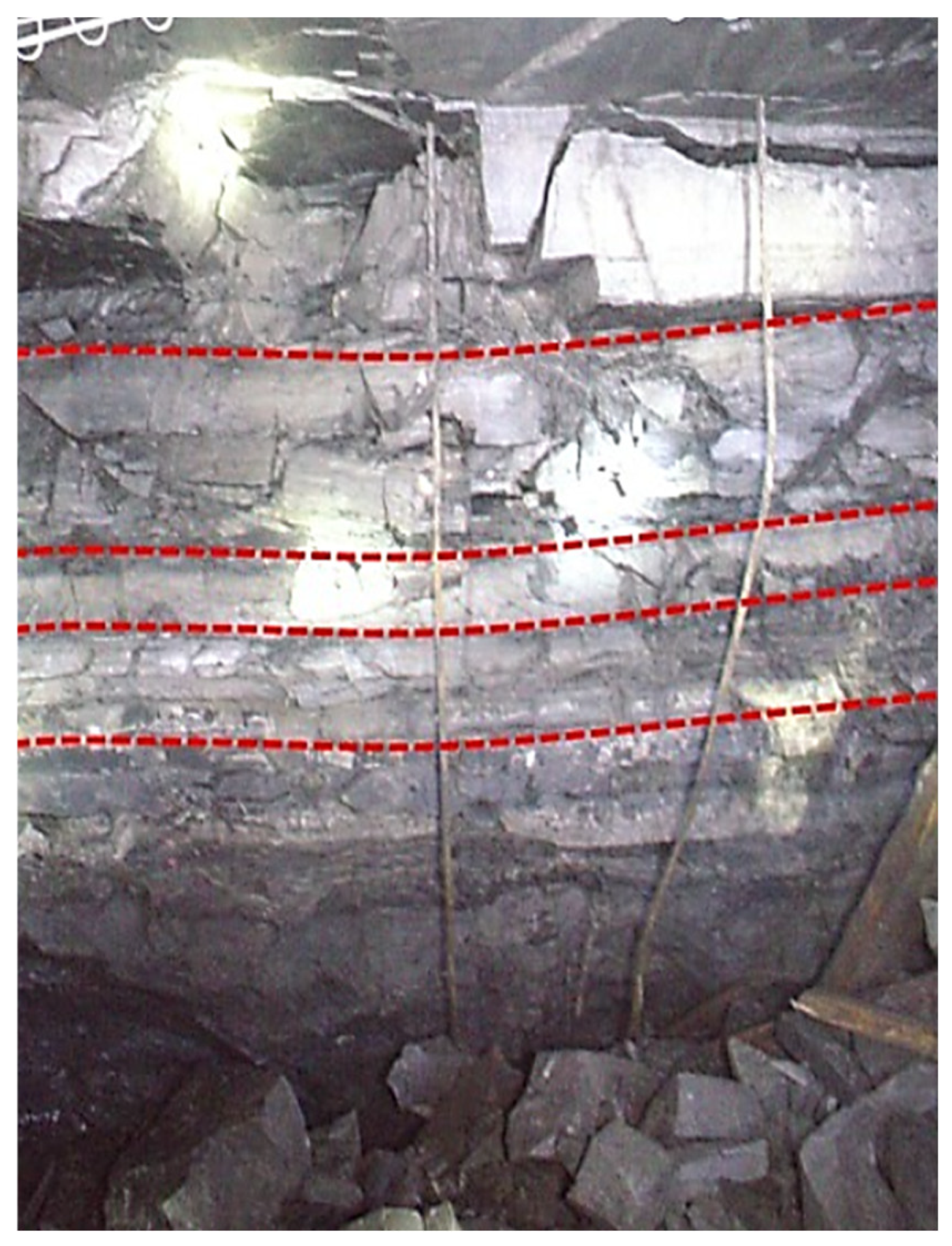
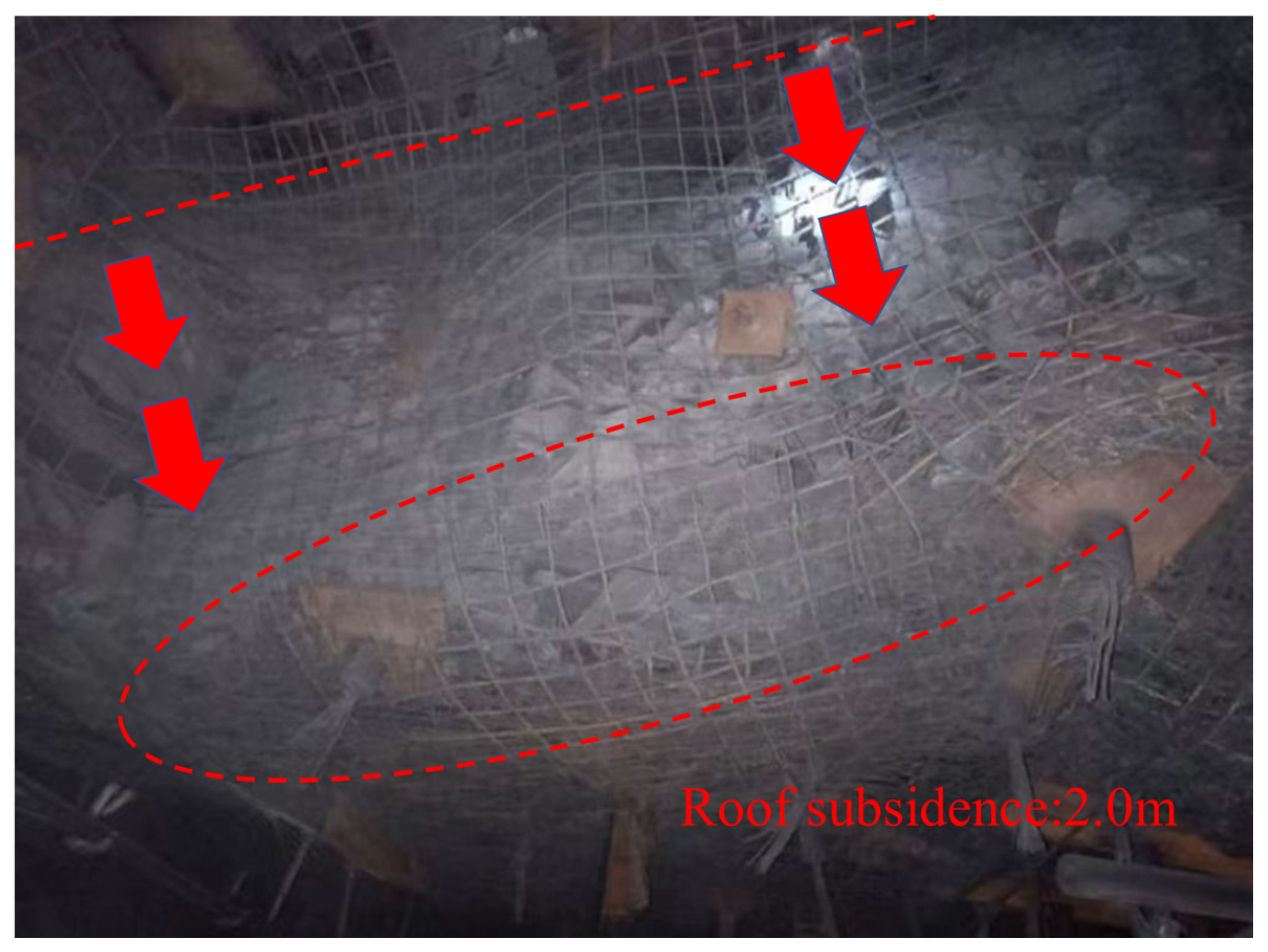
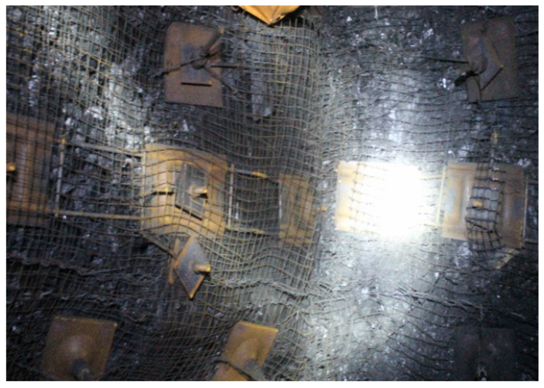
2.2. Analysis of Deformation Characteristics of Roof Rock Bolts in 41072 Roadway of Changping Mine

In order to analyze the deformation characteristics of the rock bolts on the roadway roof, six rock bolts were selected on site to analyze their deformation characteristics. The bolts in Figure 5 are directly removed during the process of roof brushing in the severely deformed area of the roadway. The deformation characteristics of roof bolt of roadway 41072 are shown in Figure 6. The 1# and 6# rock bolts are taken from the top corner positions. Obvious shear deformation occurs at the interface between the roof and the coal seam. The rock bolts in the fine sandstone section of the roof only bend within a range of 5 cm near the bedding plane. The rock bolts in the coal seam above the entire gangue are obviously bent, and the shear dislocation direction is towards the middle of the roadway. The lateral shear dislocation of the 1# rock bolt reaches 16.2 cm, and the lateral shear dislocation of the 6# rock bolt is 15.6 cm. No obvious deformation occurs in the rock bolt body below the gangue surface.
The 2# and 5# rock bolts are taken from the west two and east two positions (Figure 2). Obvious shear deformation occurs at the interface between the roof and the coal seam. The deformation form is similar to that of the top corner rock bolts. The lateral shear dislocations of the 2# and 5# rock bolts are 21.5 cm and 13.4 cm, respectively. Continuous bending deformation occurs in the rock bolt body below the gangue surface, and the bending angles are 10° and 7°, respectively.
The 3# and 4# rock bolts are taken from the middle of the roadway. Compared with the deformation of the rock bolts at other positions, the bending and shear deformation of the rock bolts in the middle is relatively small. Slight shear deformation occurs at the interface between the roof and the coal seam. The lateral dislocations are 3.7 cm and 3.3 cm, respectively. Bending deformation also occurs in the lower part of the rock bolt body below the gangue surface.

3. Model Construction of Roadway with Layered Composite Roof

3.1. Numerical Simulation of Structural Plane

According to the borehole peeping results, there are eight obvious bedding planes in the roof, which are 0.2 m, 0.4 m, 0.6 m, 0.8 m, 1.0 m, 1.3 m, and 1.8 m away from the top surface of the roadway, respectively; there is one bedding plane in the floor, which is the interface between the floor coal and rock. Based on this, a FLAC3D numerical model containing bedding was constructed, and the interface was used to simulate the bedding plane. Eight interfaces were set in the roof and one interface was set in the floor. The strength and stiffness of the interface were set much lower than that of the intact coal and rock mass to simulate the weak structural plane. At the same time, the “update” parameter of the interface was set to off to prevent the search for new contacts after the movement on the structural plane and to achieve the separation of nodes and simulate the discontinuous deformation such as the slip and opening of the weak structural plane. The mechanical performance parameters of the structural plane are shown in Table 1.

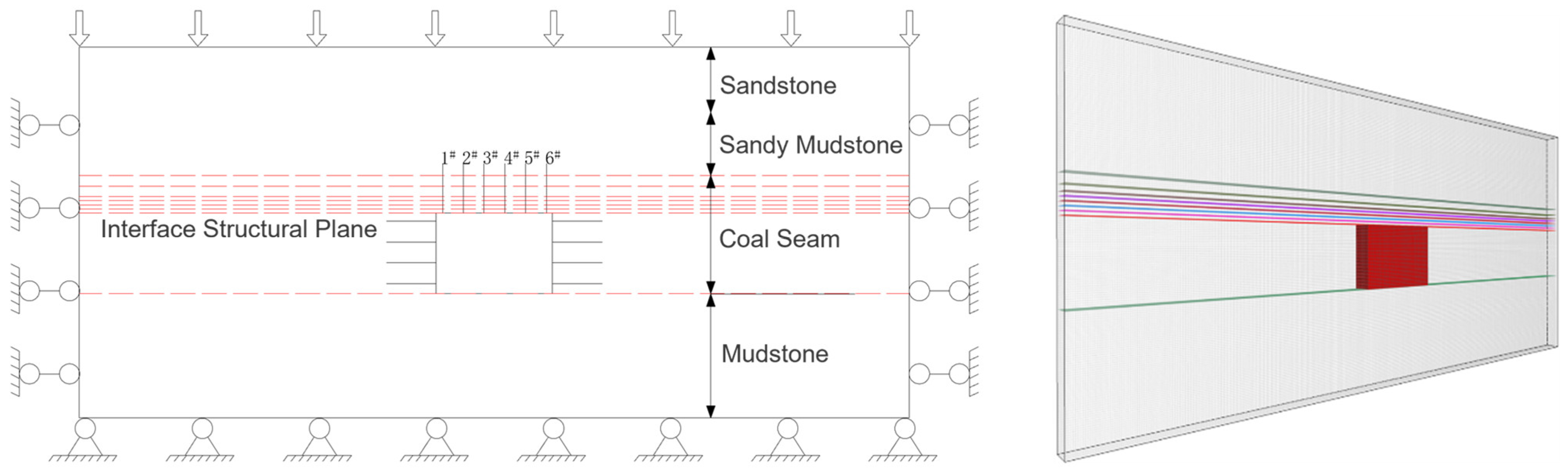
3.2. Numerical Model of Roadway with Layered Composite Roof

The model size is 40 × 1 × 17.9 m3, and a total of 20,580 elements and 30,090 nodes are divided. The thickness of the model in the Y direction is 1 m. The pile unit (the parameters of the rock bolt and the anchorage section are shown in Table 2, and each rock bolt is divided into 24 pile units) is used to simulate the rock bolt model. One row of rock bolts is arranged at Y = 0.5 m on the roadway roof, with a spacing of 800 mm, totaling six bolts, numbered from left to right as 1# to 6#, and the anchorage length is 800 mm. The maximum horizontal principal stress σH = 10 MPa, the minimum horizontal principal stress σh = 5 MPa, the vertical stress σV = 10 MPa, the axial direction of the roadway is perpendicular to the direction of the maximum principal stress, the gravitational acceleration is 10 m/s2, and the model adopts the large deformation calculation mode. A total of nine interfaces are built within the anchorage range to simulate the bedding plane. The constitutive model of the surrounding rock adopts the Mohr–Coulomb model. The boundary constraints of the model are as follows: the front and rear, left and right of the model are hinged, the bottom surface is fixed, and the corresponding stress constraints are applied on all surfaces of the model. The grid within the range of rock bolt support is refined, and the cell specification is 0.1 m × 0.1 m × 0.1 m. The model diagram is shown in Figure 7 and Figure 8.

4. Simulation Realization of Rock Bolt Pile Unit

4.1. Numerical Model of Roadway with Layered Composite Roof

In FLAC3D, the cable unit is generally used to simulate rock bolts, but the cable unit can only bear axial loads and cannot reflect shear loads, while the shear resistance of rock bolts has a great influence on the support effect. In order to better simulate the comprehensive effect of the tensile and shear resistance of rock bolts, the pile unit is selected: The pile unit combines the beam element and the anchor cable element. Besides being able to bear the axial pulling load, it also has the ability to resist bending and shear; The pile unit can also calculate the stress softening between the pile and the grid and the rupture of the pile, thereby simulating the rupture of the rock bolt and the decoupling of the anchorage interface. The use of the pile unit can better simulate the mechanical behaviors, such as tension, bending, shear, fracture, and anchor failure of the rock bolt. In this paper, the HBRB500 high-strength rock bolt with a diameter of 22 mm is uniformly used for simulation. The drilling diameter is 30 mm. The parameters of the rock bolt and the anchoring agent are listed in Table 2.
In the pile unit, “cs-scoh” refers to the peak bond force, which determines when the bonding interface decouples and detaches from the anchor; “cs-sk” refers to the bond stiffness, which determines the resistance-increasing speed of the anchorage body; cs-scoh and cs-sk jointly determine the mechanical properties of the anchorage body and have a very significant influence on the support effect. To provide a basis for determining cs-scoh and cs-sk of the numerical rock bolt, a pull-out test was carried out in the laboratory. A steel pipe with a length of 125 mm and an inner diameter of 30 mm was used to simulate the drilling hole, and a left-handed high-strength threaded steel with a diameter of 22 mm was selected for the rock bolt. After repeated tests, when the anchorage section length was 125 mm, the average maximum pull-out force was 140 kN, and the corresponding average displacement was 13 mm. Calculate cs-scoh = 1.12 × 10⁶ N/m. Considering that the on-site rock bolts are anchored in the coal and rock mass, the peak strength of the bonding interface should be lower than the laboratory test results. Zhu et al. [27] took advantage of the repeatability and scalability of numerical simulation calculations and proposed calibrating the mechanical parameters of the coal and rock mass through the repetitive trial-and-error method. In this paper, the above method was adopted to obtain cs-scoh = 4.37 × 10⁵ N/m, cs-sk = cs-scoh/13 mm = 3.3 × 10⁷ N/m. The parameters of pile Units are shown in Table 3.

4.2. Method of Applying Pretension Force of Pile Unit

In FLAC3D, there is no direct command to apply the pretension force to the rock bolts simulated by the pile unit. Through the built-in fish script of FLAC3D, this paper proposes the method of “break−tension−suture”, realizing the application of the pretension force to the rock bolts simulated by the pile unit.
The rock bolt is 2.4 m long and is simulated using 24 pile units. The anchorage section is 0.8 m long, and the free section is 1.6 m long. Two sections of pile units are created at the position where the rock bolt is set. The shorter section contains eight pile units and simulates the anchorage section. The parameters are set according to the parameters of the anchorage section pile unit in Table 3. The longer section contains 17 pile units and simulates the free section of the rock bolt. The cs-scoh and cs-sk of the pile unit in the free section are both set to 0, and other parameters are the same as those of the anchorage section. A rigid connection is established between the tail of the pile unit in the free section and the surrounding grid to simulate the rock bolt tray (Figure 9a).
Tension loads are applied to the nodes at the openings of the anchorage section and the free section of the rock bolt. The magnitude of the tension load is the preset pretension force of the rock bolt. The pile unit is stretched, and the operation is balanced to simulate the application process of the pretension force of the rock bolt (Figure 9b,c). Taking the two nodes at the openings of the anchorage section and the free section as the starting and ending points, a new pile unit is established. The parameters are set according to the pile unit in the free section. The opening of the rock bolt is “sutured”, and the tension load applied to the nodes is deleted. The operation is balanced to complete the pretension of the rock bolt. The grid is released, and the operation is carried out to realize the diffusion of the prestress in the surrounding rock (Figure 9d). It should be noted that due to the calculation of flexible structures and ultimate bearing capacity involved in the simulation, a large deformation calculation mode is adopted in the simulation.
The shape of the support stress field after the pretension of the rock bolt by the above method is observed. The overall compressive stress zone is in a “pomegranate shape”. The magnitude and shape are quite consistent with the support stress field shapes in the similar simulation by Lin [28] and the numerical simulation by Zhang [29]. This proves the effectiveness of the “break-tension-suture” method.

5. Simulation Analysis of Deformation and Stress Characteristics of Rock Bolts

5.1. Calculation Sequence

The pressure of the surrounding rock in the roadway ahead of the tunneling face begins to be relieved. After the roadway is excavated, the stress in the shallow part of the surrounding rock is rapidly released. After the rock bolts are installed and pretensioned, the diffusion of the pretension force and the unloading of the in situ stress of the original rock occur simultaneously. The surrounding rock continuously migrates under the combined action of the in situ stress field of the original rock, the mining-induced stress field and the stress field of the rock bolt support until it reaches equilibrium.
In order to correspond to the above stress change process, the calculation sequence is set as follows: Initialize the numerical model, apply the in situ stress and calculate the equilibrium; excavate the roadway, apply the in situ stress on the periphery (roof, floor, and two sides) and gradually reduce it to simulate the real release process of the surrounding rock stress after the roadway excavation. The power exponential equation is used for the release, that is, the release is fast at the beginning and slow in the later stage; when the stress is released to 30% of the in situ stress [30], fix the grid, install the rock bolts and pretension them using the “break-tension-suture” method; release the grid, and the surrounding rock continues to migrate under the combined action of the in situ stress field of the original rock, the mining-induced stress field and the stress field of the rock bolt support until it reaches equilibrium. The calculation sequence is shown in Figure 10.

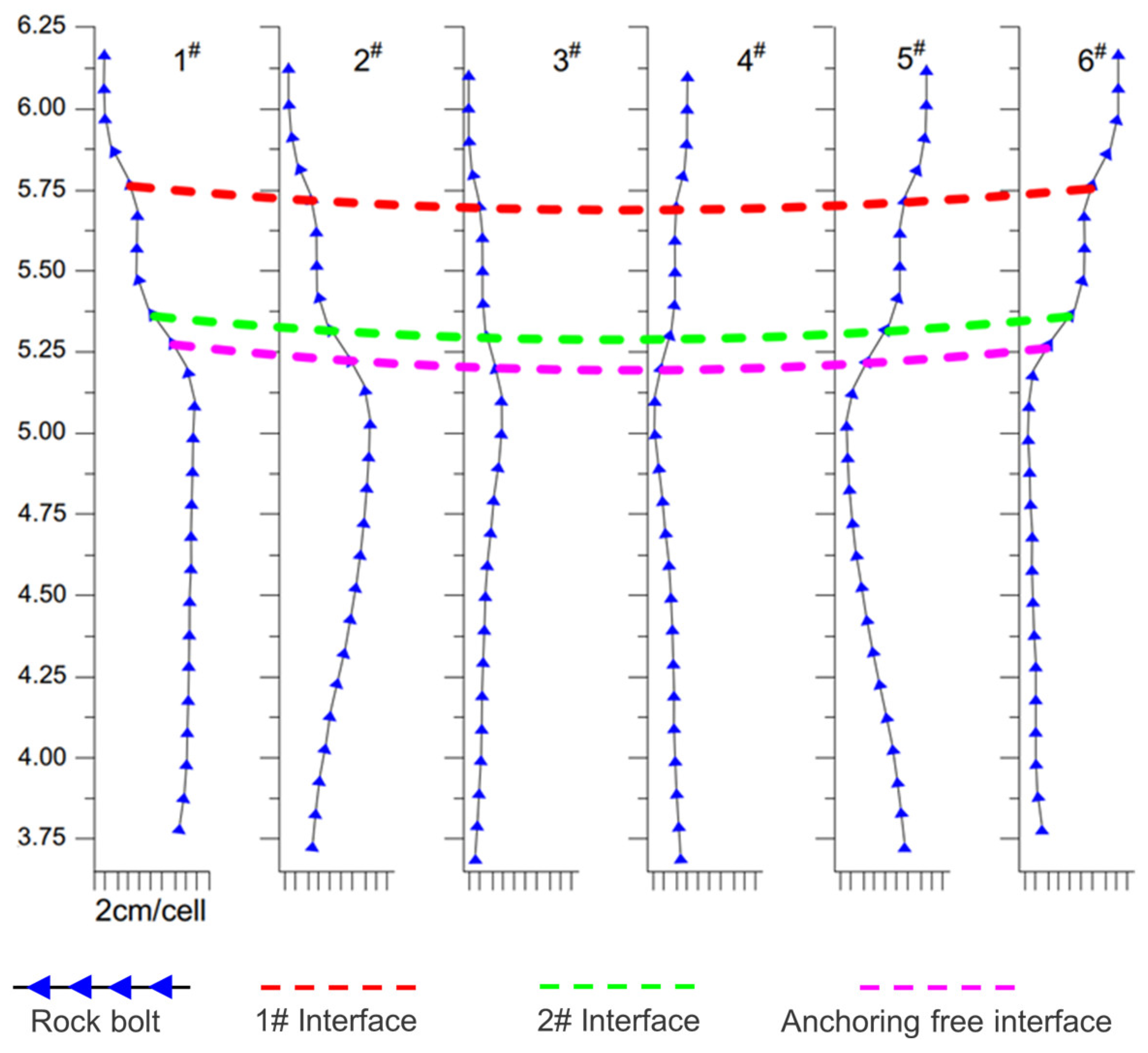
5.2. Simulation Analysis of Rock Bolt Deformation

The horizontal stress of the roadway surrounding rock is an important factor affecting the deformation of rock bolts. With the increase in horizontal stress, the deformation of rock bolts increases significantly. At this time, the subsidence of the roadway roof, floor heave, and displacements of the two sides increase significantly. The angle between the axial direction of the roadway and the maximum horizontal stress is different, and the degree of its influence on the deformation of rock bolts also varies. When the axial direction of the roadway is parallel to the direction of the maximum horizontal stress, the deformation of the rock bolts is the smallest. When the axial direction forms an acute angle with the direction of the maximum horizontal stress, the deformation of the rock bolts is biased towards one side of the roadway. When the axial direction is perpendicular to the maximum horizontal stress, the influence is the greatest, and obvious deformation occurs in the rock bolts. The deformation of the rock bolts obtained according to the simulation calculation method is shown in Figure 11. The 1# rock bolt shows obvious shear deformation at the interface between the roof and the coal seam. The shear dislocation direction is towards the middle of the roadway, and the dislocation distance is 13.3 cm. The 2# rock bolt shows obvious shear deformation at the interface between the roof and the coal seam. The deformation form is similar to that of the 1# rock bolt, and its lateral dislocation distance is 12.3 cm. Continuous bending deformation occurs in the lower part of the gangue, and the bending angle is 4.5°. The 3# rock bolt shows shear deformation at the interface between the roof and the hard coal, and the lateral dislocation distance is 4.1 cm. Compared with the 1# and 2# rock bolts, its bending deformation degree is smaller.
The deformation form of the rock bolts in the field and the simulation is consistent, both deforming and expanding towards the interior of the roadway along the interface of the roof coal seam with the center line of the roadway as the axis. In terms of the degree of deformation, the lateral dislocations of the 1# and 3# rock bolts in the field and the simulation are 16.2 cm, 13.3 cm, 3.7 cm, and 4.1 cm, respectively. The errors are 0.179 and 0.098. To sum up, compared with the actual deformation of the roof rock bolts in the 41072 roadway of Changping Mine (Figure 6), the simulation results of the rock bolt deformation are relatively consistent in terms of the deformation form and degree, indicating that the model parameter selection is reasonable, the calculation sequence is relatively consistent with the actual excavation process, and the model can be used to analyze the deformation of the bolt body.

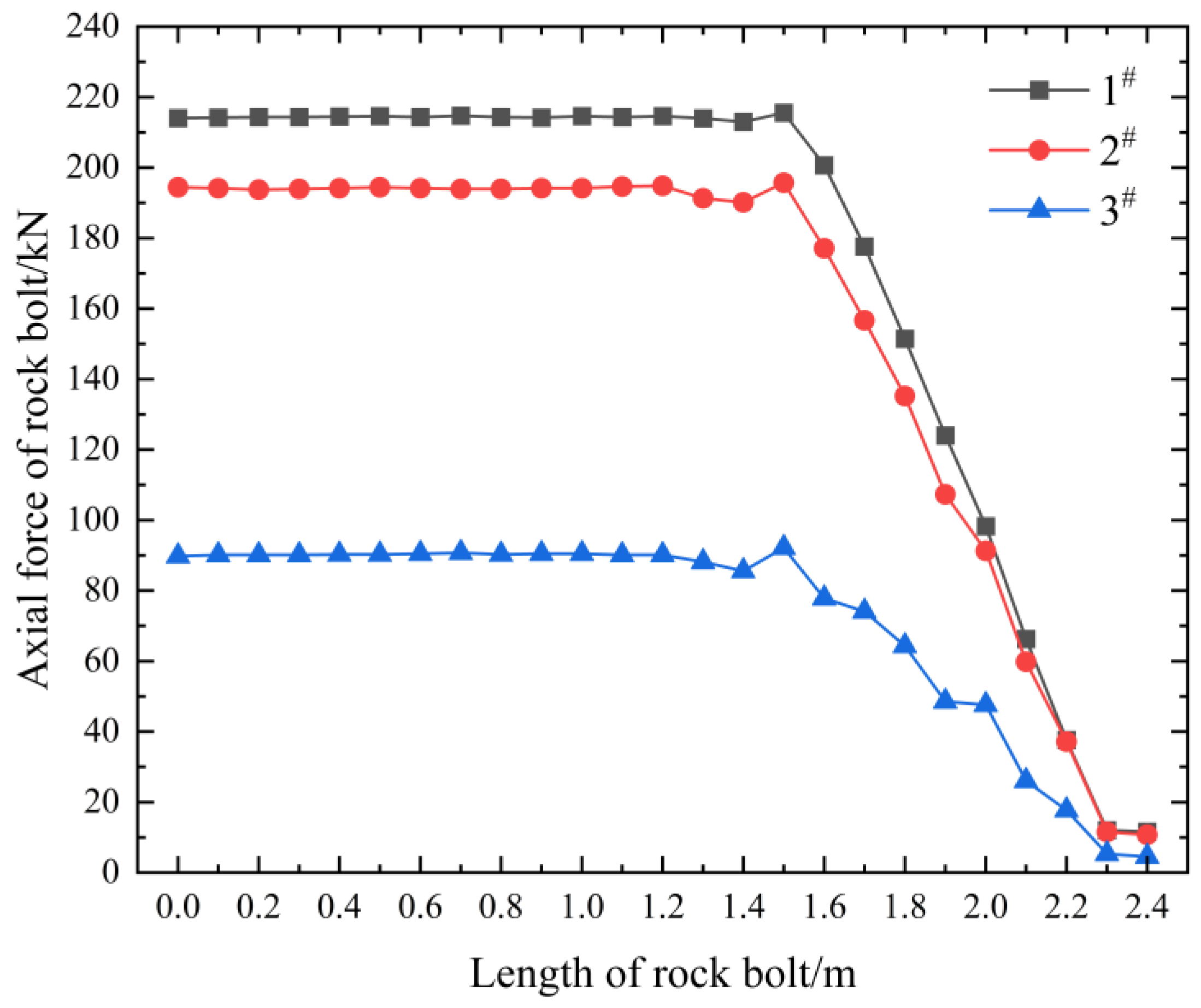
5.3. Simulation Analysis of Rock Bolt Force

The force conditions of the rock bolts are shown in Figure 12 and Figure 13. The axial force of the 1# rock bolt is the smallest, which is 84.5 kN, indicating that the subsidence of the surrounding rock within its support range is small. The axial force of the anchorage section increases greatly at the interface between the roof and the coal seam, indicating that there is a separation layer at this interface. The axial force of the 2# rock bolt is the largest, which is 204.8 kN, indicating that the surrounding rock within its support range has a large subsidence and obvious separation layer. The axial force of the 3# rock bolt is slightly lower than that of the 2# rock bolt, which is 180.3 kN. There is no obvious change in the axial force of the anchorage section at the interface between the roof and the coal seam, indicating that the rock layers at this location have coordinated subsidence and the separation layer at the interface is small. The 1#, 2#, and 3# rock bolts are all subject to a large shear force at the interface between the roof and the coal seam. The shear force of the 1# rock bolt is the largest, which is 105.3 kN. It is not subject to shear force at the gangue surface and the interface between the anchorage and the free section, indicating that the coal seams above and below the gangue surface deform coordinately and there is no dislocation. Therefore, the force conditions of the 1#, 2#, and 3# rock bolts correspond to the deformation characteristics of the bolt bodies. In addition, according to the technical specifications of rock bolt support for coal mine roadways, the maximum bearing capacity of the roof rock bolts in the roadways of Changping Mine is 125 kN. Therefore, according to the simulated actual force conditions of the rock bolts, the safety factors of 1#, 2#, and 3# rock bolts during operation are calculated to be 1.48, 0.61, and 0.69, respectively. Under normal circumstances, the safety factor of rock bolts should be between 1.5 and 2.5. Within this range, the stability requirements of coal mine roadways can be met. Therefore, the above-mentioned rock bolts all undergo obvious deformation and lose their bearing capacity during actual operation, which is consistent with the on-site monitoring results of rock bolt deformation, once again verifying the reliability of the simulation method in this paper.

6. Analysis of Influencing Factors of Rock Bolt Body Deformation

6.1. Simulation Schemes of Different Surrounding Rock and Structural Plane Strengths

With the continuous improvement in the quality of the steel of the rock bolt body, the tensile strength of the rock bolt body continues to increase. Pure tensile fractures of rock bolts rarely occur at the site of roadway support. The fracture form of rock bolts is generally tensile–shear fracture. Therefore, the influencing factors of the shear and bending deformation of rock bolts should be analyzed. Based on the simulation of the 41072 roadway in Changping Mine in this section, four groups of comparative simulations were conducted to analyze the influence of the strength of the surrounding rock and the strength of the structural plane on the shear and bending deformation of the rock bolts. The details are shown in Table 4.

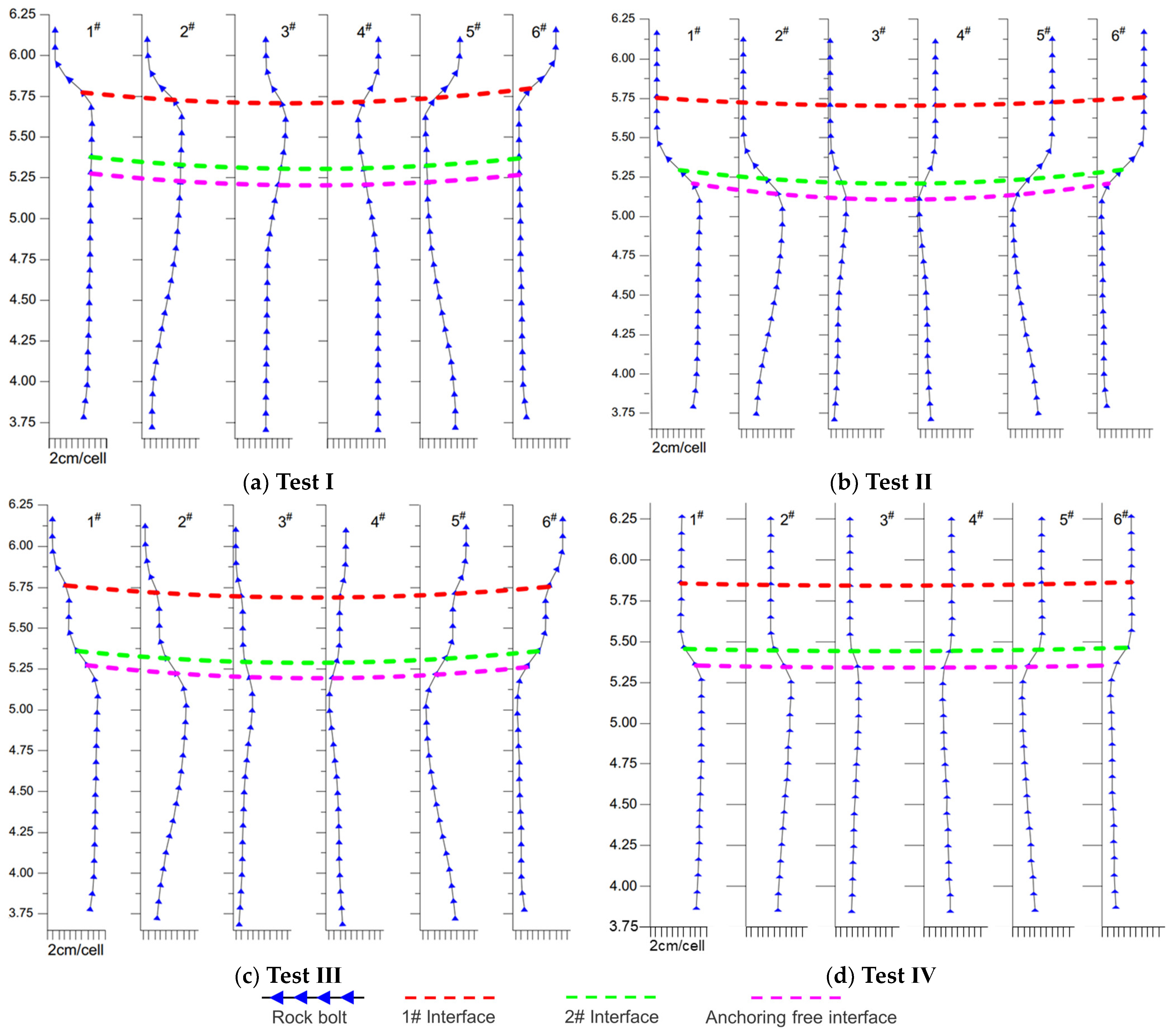
6.2. Analysis of Simulation Results

6.2.1. The Deformation Characteristics of Rock Bolts

Based on the roadway model with layered composite roof constructed in the above text, the deformation characteristics of the anchor bolt body under different factors were simulated. Figure 14 shows the simulation results of the deformation characteristics of the anchor bolt under different strengths of the surrounding rock and structural planes.
It can be concluded from Figure 14 that in Test I, no obvious deformation occurred at the 1# interface of the bolt body, and the relative dislocation was not obvious, but obvious shear deformation occurred at the 2# interface of the anchor bolt, and there was a large relative dislocation of the rock strata above and below the 2# interface. In Test II, shear deformation occurred at both the 1# and 2# interfaces of the anchor bolt, and the relative dislocation of the upper and lower rock strata was obvious, but the deformation degree of the anchor bolt near the 1# interface was smaller than that near the 2# interface. In Test III, obvious shear deformation occurred at the 1# interface, and the relative dislocation was obvious, while no obvious deformation occurred at the 2# interface, and the relative dislocation was not obvious. In Test IV, shear deformation occurred at both the 1# and 2# interfaces of the anchor bolt, and the relative dislocation of the upper and lower rock strata was obvious. Comparing the deformation of the anchor bolt near the 2# interface of Test I and the 1# interface of Test II, it can also be shown that under the condition of the same structural plane strength, the higher the strength of the surrounding rock, the smaller the shear and bending deformation of the anchor bolt. Comparing the deformation of the anchor bolt near the 2# interface of Test I and the 2# interface of Test IV, the strength of both interfaces was small, and the difference in the strength of the rock strata above and below the interface was also large. The weak coal seam of the 2# interface in Test I was below the interface, and the weak coal seam in Test IV was above the 2# interface. This indicates that under the condition of the same structural plane strength, when the weak rock mass is below the structural plane, the structural plane is more prone to transverse dislocation.

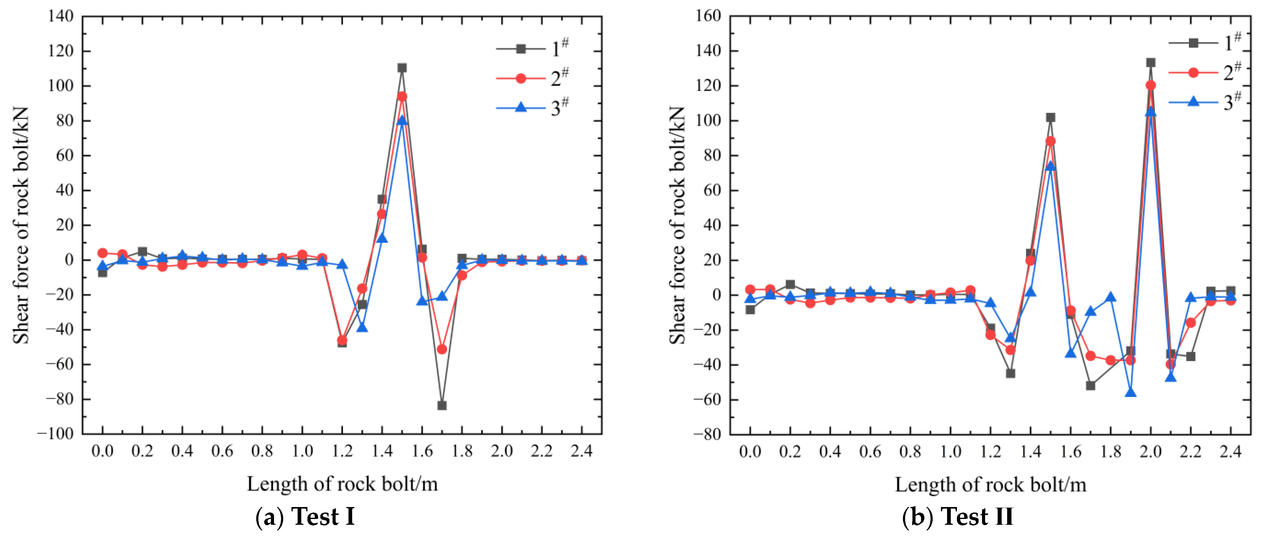
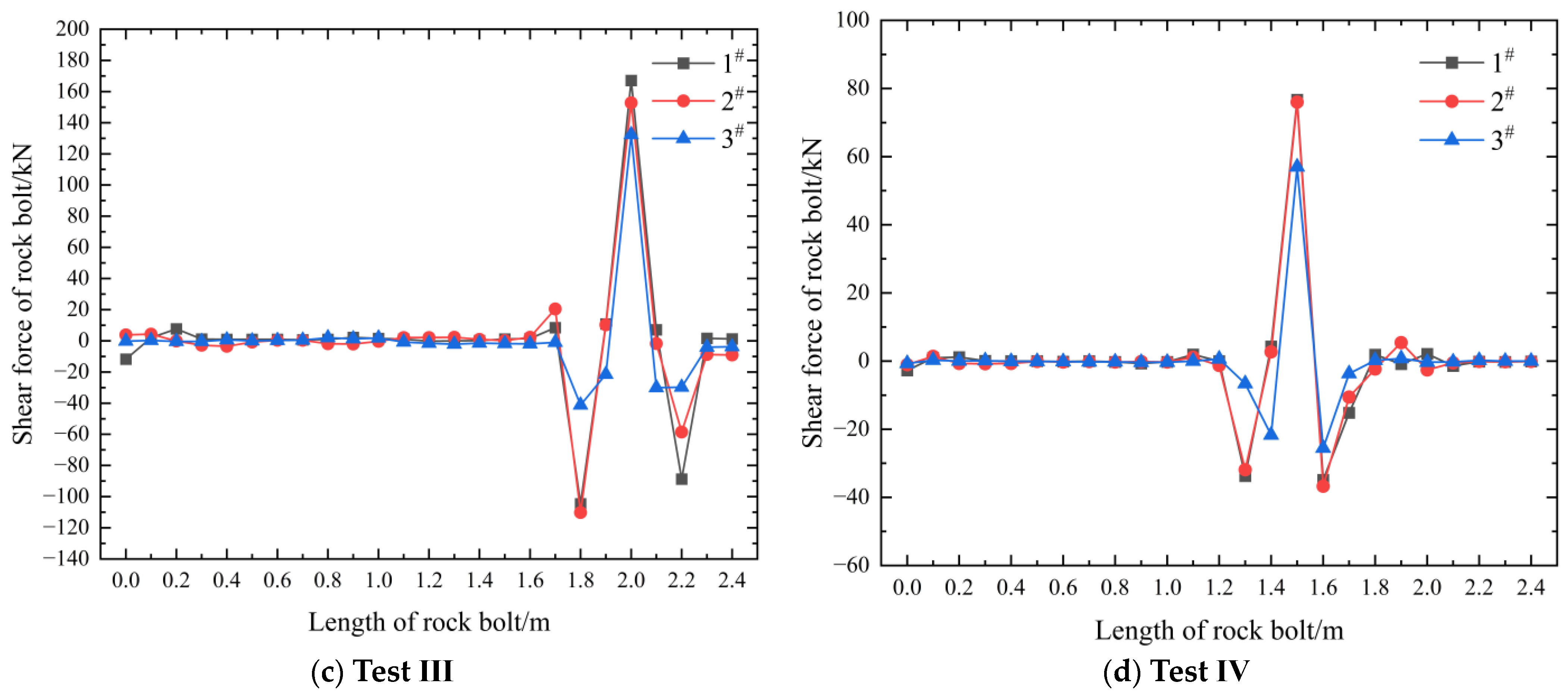
6.2.2. The Force Analysis of Rock Bolts

During the simulation process, the axial force and shear force at each position of the anchor bolt body were monitored in real time to reveal the deformation and force characteristics and influencing factors of the anchor bolt body under the action of the layered composite roof. Figure 15 and Figure 16, respectively, show the axial force and shear force characteristics of the anchor bolts with different strengths of the surrounding rock and structural planes.
It can be concluded from Figure 15 and Figure 16 that in Test I, the axial force and shear force of the bolt body increased significantly at the 2# interface, so the bolt body underwent obvious deformation at the 2# interface, while no obvious deformation occurred at the 1# interface, and the shear force condition also indicated that the bolt body was not subjected to shear at this point. In Test II, the axial force of the bolt body increased significantly at the 1# interface, and the shear force of the bolt body also indicated that the bolt body was subjected to obvious shear at the 1# interface. The 2# interface was located in the non-anchored section of the anchor bolt, and it was impossible to determine whether the axial force increased nearby, but the shear force condition of the bolt body indicated that the bolt body was subjected to shear force at this point. Comparing the bending deformation conditions of the anchor bolts near the 1# and 2# interfaces, the deformation degree of the anchor bolt near the 1# interface was smaller than that near the 2# interface, but the shear force of the anchor bolt near the 1# interface was higher than that near the 2# interface, indicating that when the surrounding rock strength was higher, the anchor bolt could mobilize a greater deformation resistance with a smaller deformation. In Test III, the axial force of the bolt body increased significantly at the 1# interface, and the shear force of the bolt body also indicated that the bolt body was subjected to obvious shear at the 1# interface. No obvious deformation occurred at the 2# interface, and the shear force condition also indicated that the bolt body was not subjected to shear at this point. In Test IV, the axial force of the bolt body did not increase significantly at the 1# interface, and the shear force of the bolt body indicated that the bolt body was not subjected to obvious shear at the 1# interface. However, the shear force of the bolt body at the 2# interface increased significantly, and the bolt body also underwent obvious shear deformation.
Analyzing the above four tests, when the strength of the structural plane was small, the rock strata near the structural plane all underwent lateral dislocation, indicating that the strength of the structural plane was the primary factor controlling the lateral dislocation of the structural plane. Secondly, when the strength of the surrounding rock above and below the structure differed greatly, the structural plane was also prone to lateral dislocation, which was caused by the uncoordinated deformation of the rock strata above and below the structural plane. When the weak rock layer was located below the structural plane, the lateral dislocation of the structural plane was more likely to occur.
To sum up, the rock bolt and the roadway surrounding rock have an interactive relationship. In addition to the strength of the surrounding rock itself, the strength of the bedding of the roadway surrounding rock structural plane is also an important factor affecting the force, deformation and failure of the rock bolt. Cai et al. [31] used a linear drop model once to analyze the stress distribution characteristics of the rock bolt under the opening of the bedding rock mass. It shows that the opening of the bedding applies tensile stress to the rock bolt. Li and Stillborg et al. [32] believe that when the bedding strength of the surrounding rock is small, it generates a large axial tensile force on both sides of the rock bolt, which leads to decoupling of the anchoring interface and gradually expands to both sides. Hyett et al. [33] believe that the shear stress of the anchoring interface has a linear relationship with the deformation of the rock bolt and the surrounding rock and further analyzed the influence of the anchoring interface and the bedding strength on the force and deformation of the rock bolt. The above research results are consistent with this paper. When the bedding strength of the structural plane is low, the strength of the upper and lower rock strata differs greatly, and the weak rock layer is located below the structural plane, the rock bolt is most prone to lateral dislocation.

7. Conclusions

(1) Six rock bolts at the roadway roof were selected on site to analyze their deformation characteristics. It was found that the bending and shear deformation of the rock bolts in the middle of the roadway roof was relatively small, and slight shear deformation occurred at the interface between the roof and the coal seam, with the lateral shear dislocation being 3.7 cm and 3.3 cm, respectively. However, the rock bolts at the two top corners of the roadway showed obvious shear deformation at the interface between the roof and the coal seam, with the lateral shear dislocation being 16.2 cm and 15.6 cm, respectively.
(2) A “break-tension-suture” method for applying the pretension force of the pile unit simulation rock bolt was proposed. The interface was used to simulate the weak surface of the layered composite roof structure, and a reasonable calculation sequence of the stress field of the surrounding rock before and after the rock bolt was invented. Using the above simulation method to invert the deformation characteristics of the on-site rock bolts, it was found that the simulated deformation form and degree of the rock bolts were relatively consistent with the on-site situation. The lateral dislocations of 1# and 3# rock bolts on site and in the simulation were 16.2 cm, 13.3 cm, 3.7 cm, and 4.1 cm, respectively, indicating that the simulation method was reliable, the parameter selection was reasonable, and the calculation sequence was consistent with the actual excavation process.
(3) A unified model of deformation and stress evolution of rock bolts in the layered composite roof roadway was constructed. The influences of the strength of the surrounding rock and the strength of the structural plane on the shear and bending deformation of the rock bolts were analyzed. It was found that the influencing factors of the rock bolt deformation were the strength of the structural plane > the strength of the surrounding rock. When the strength of the structural plane was low, the strength difference between the upper and lower rock layers was large, and the weak rock layer was located below the structural plane, the rock bolts were most prone to lateral dislocation.
(4) This study found that the deformation of the top corner bolt was the largest, and on-site measurements were conducted to strengthen the top corner bolt monitoring. Furthermore, regarding the impact of structural deformation on bolts, grouting reinforcement can be adopted on site to ensure the integrity of the roadway roof. This article did not change the pretension force of the bolts in the simulation. However, on-site practice has shown that the active restraining force provided by high pretensioning bolts can not only limit the opening of weak surfaces in the structure, but also increase the shear strength of the structural surface and suppress its activity. Thus, future research will focus on the influence of pretension on bolt deformation.

Author Contributions

Z.W. and C.Z. conceived and designed the study. C.Z. and S.F. were involved in the numerical simulation and analysis. Z.W. was involved in the field measurement and prepared all figures. All authors have read and agreed to the published version of the manuscript.

Funding

Financial support for this work is provided by the National Key R&D Program of China (2023YFC2907602), the Science and Technology Innovation and Entrepreneurship Fund of Tiandi Science and Technology Co., Ltd. (2023-TD-ZD011-001), the National Natural Science Foundation of China (52104155), and the Fundamental Research Funds for the Central Universities (2024ZKPYNY01).

Data Availability Statement

All data used to support the findings of this study are available from the corresponding author upon request.

Conflicts of Interest

The authors declare no conflicts of interest.

References

  1. Jodeiri Shokri, B.; Mirzaghorbanali, A.; Nourizadeh, H.; McDougall, K.; Karunasena, W.; Aziz, N.; Entezam, S.; Entezam, A. Axial Load Transfer Mechanism in Fully Grouted Rock Bolting System: A Systematic Review. Appl. Sci. 2024, 14, 2076–3417. [Google Scholar] [CrossRef]
  2. Chen, J.; Liu, P.; Zhao, H.; Zhang, C.; Zhang, J. Analytical studying the axial performance of fully encapsulated rock bolts. Eng. Fail. Anal. 2021, 128, 105580. [Google Scholar] [CrossRef]
  3. Zhang, K.; Zhang, G.; Hou, R.; Wu, Y.; Zhou, H. Stress evolution in roadway rock bolts during mining in a fully mechanized longwall face, and an evaluation of rock bolt support design. Rock Mech. Rock Eng. 2015, 48, 333–344. [Google Scholar] [CrossRef]
  4. Zhang, C.; Bai, Q.; Han, P. A review of water rock interaction in underground coal mining: Problems and analysis. Bull. Eng. Geol. Environ. 2023, 82, 157. [Google Scholar] [CrossRef]
  5. Zhang, C.; Zhao, Y.; Han, P.; Bai, Q. Coal pillar failure analysis and instability evaluation methods: A short review and prospect. Eng. Fail. Anal. 2022, 138, 106344. [Google Scholar] [CrossRef]
  6. Chen, Y.; Xiao, H. State-of-the-art on the anchorage performance of rock bolts subjected to shear load. Int. J. Coal Sci. Technol. 2024, 11, 9. [Google Scholar] [CrossRef]
  7. Gu, S.C.; Wang, P.; Yang, C.F. Mechanical characteristics and stability analysis of surrounding rock reinforcement in rectangular roadway. Sci. Rep. 2022, 12, 22234. [Google Scholar] [CrossRef]
  8. Nourizadeh, H.; Mirzaghorbanali, A.; Serati, M.; Mutaz, E.; McDougall, K.; Aziz, N. Failure characterization of fully grouted rock bolts under triaxial testing. J. Rock Mech. Geotech. Eng. 2024, 16, 778–789. [Google Scholar] [CrossRef]
  9. Entezam, S.; Shokri, B.J.; Nourizadeh, H.; Motallebiyan, A.; Mirzaghorbanali, A.; McDougall, K.; Aziz, N.; Karunasena, K. Investigation of the Effect of Using Fly Ash in the Grout Mixture on Performing the Fully Grouted Rock Bolt Systems; University of Wollongong: Wollongong, NSW, Australia, 2023. [Google Scholar]
  10. Yu, S.; Niu, L.; Chen, J. Experimental and Numerical Studies on Bond Quality of Fully Grouted Rockbolt under Confining Pressure and Pull-Out Load. Shock Vib. 2022, 2022, 7012510. [Google Scholar] [CrossRef]
  11. Jodeiri Shokri, B.J.; Entezam, S.; Nourizadeh, H.; Motallebiyan, A.; Mirzaghorbanali, A.; McDougall, K.; Aziz, N.; Karunasena, K. The effect of changing confinement diameter on axial load transfer mechanisms of fully grouted rock bolts. In Proceedings of the 2023 Resource Operators Conference, University of Wollongong, Wollongong, NSW, Australia, 9–10 February 2023; pp. 290–295. [Google Scholar]
  12. Nourizadeh, H.; Mirzaghorbanali, A.; McDougall, K.; Jeewantha, L.; Craig, P.; Motallebiyan, A.; Shokri, B.J.; Rastegarmanesh, A.; Aziz, N. Characterization of mechanical and bonding properties of anchoring resins under elevated temperature. Int. J. Rock Mech. Min. Sci. 2023, 170, 105506. [Google Scholar] [CrossRef]
  13. He, M.; Ren, S.; Guo, L.; Lin, W.; Zhang, T.; Tao, Z. Experimental study on influence of host rock strength on shear performance of Micro-NPR steel bolted rock joints. Int. J. Rock Mech. Min. Sci. 2022, 159, 105236. [Google Scholar] [CrossRef]
  14. He, M.; Ren, S.; Xu, H.; Luo, S.; Tao, Z.; Zhu, C. Experimental study on the shear performance of quasi-NPR steel bolted rock joints. J. Rock Mech. Geotech. Eng. 2023, 15, 350–362. [Google Scholar] [CrossRef]
  15. Tahmasebinia, F.; Yang, A.; Feghali, P.; Skrzypkowski, K. Structural evaluation of cable bolts under static loading. Appl. Sci. 2023, 13, 1326. [Google Scholar] [CrossRef]
  16. Tahmasebinia, F.; Yang, A.; Feghali, P.; Skrzypkowski, K. A numerical investigation to calculate ultimate limit state capacity of cable bolts subjected to impact loading. Appl. Sci. 2022, 13, 15. [Google Scholar] [CrossRef]
  17. Chen, Y.; Lin, H.; Xie, S.; Ding, X.; He, D.; Yong, W.; Gao, F. Effect of joint microcharacteristics on macroshear behavior of single-bolted rock joints by the numerical modelling with PFC. Environ. Earth Sci. 2022, 81, 276. [Google Scholar] [CrossRef]
  18. Jiang, Y.; Zhang, S.; Luan, H.; Wang, C.; Wang, G.; Han, W. Numerical modelling of the performance of bolted rough joint subjected to shear load. Geomech. Geophys. Geo-Energy Geo-Resour. 2022, 8, 140. [Google Scholar] [CrossRef]
  19. Zhan, K.; Wen, X.; Wang, X.; Kong, C. A method for characterization of stress concentration degree of coal mine roadway surrounding rock. J. Geophys. Eng. 2023, 20, 699–711. [Google Scholar] [CrossRef]
  20. Kong, Q.; Li, Y.; Wang, S.; Yuan, C.; Sang, X. The influence of high-strength bolt preload loss on structural mechanical properties. Eng. Struct. 2022, 271, 114955. [Google Scholar] [CrossRef]
  21. Yi, W.; Wang, M.; Zhao, S.; Tong, J.; Liu, C. The effect of rock hardness and integrity on the failure mechanism of mortar bolt composite structure in a jointed rock mass. Eng. Fail. Anal. 2023, 143, 106831. [Google Scholar] [CrossRef]
  22. Peng, S. Roof bolting and underground roof falls. Geohazard Mech. 2023, 1, 32–37. [Google Scholar] [CrossRef]
  23. Ren, S.; Tao, Z.; He, M.; Li, M.; Sui, Q. Numerical simulation study on shear resistance of anchorage joints considering tensile–shear fracture criterion of 2G-NPR bolt. Int. J. Coal Sci. Technol. 2023, 10, 58. [Google Scholar] [CrossRef]
  24. Zhang, Y.; Jiang, Y.; Wang, Z.; Yin, Q.; Chen, M. Anchorage effect of bolt on en-echelon fractures: A comparison between energy-absorbing bolt and conventional rigid bolt. Eng. Fail. Anal. 2022, 137, 106256. [Google Scholar] [CrossRef]
  25. Yang, W.; Xia, X. Study on mining failure law of the weak and weathered composite roof in a thin bedrock working face. J. Geophys. Eng. 2018, 15, 2370–2377. [Google Scholar] [CrossRef]
  26. Ma, S.; Wang, Y.; Wang, H.; Gao, L. Stability mechanism and control technology of large inclined working face roof in large-scale caving area. J. Geophys. Eng. 2023, 20, 91–102. [Google Scholar] [CrossRef]
  27. Zhu, D.; Yu, B.; Wang, D.; Zhang, Y. Fusion of finite element and machine learning methods to predict rock shear strength parameters. J. Geophys. Eng. 2024, 21, gxae064. [Google Scholar] [CrossRef]
  28. Lin, J.; Shi, Y.; Sun, Z.Y.; Wang, Z.S.; Cai, J.F. Large scale model test on the distribution characteristics of the prestressed field of end-anchored bolts. Chin. J. Rock Mech. Eng. 2016, 35, 2237–2247. [Google Scholar]
  29. Zhang, Z.; Kang, H.P.; Wang, J.H. Pre-tensioned stress coordination function analysis of bolt-cable anchor support in coal roadway. J. China Coal Soc. 2010, 35, 881–886. [Google Scholar]
  30. Kang, H.P.; Jiang, P.F.; Gao, F.Q. Analysis on stability of rock surrounding heading faces and technical approaches for rapid heading. J. China Coal Soc. 2021, 46, 2023–2045. [Google Scholar]
  31. Cai, Y.; Esaki, T.; Jiang, Y. A rock bolt and rock mass interaction model. Int. J. Rock Mech. Min. Sci. 2004, 41, 1055–1067. [Google Scholar] [CrossRef]
  32. Li, C.; Stillborg, B. Analytical models for rock bolts. Int. J. Rock Mech. Min. Sci. 1999, 36, 1013–1029. [Google Scholar] [CrossRef]
  33. Hyett, A.J.; Moosavi, M.; Bawden, W.F. Load distribution along fully grouted bolts, with emphasis on cable bolt reinforcement. Int. J. Numer. Anal. Methods Geomech. 1996, 20, 517–544. [Google Scholar] [CrossRef]
Figure 1. Layout of 41072 Roadway.
Applsci 14 06694 g001
Figure 2. Support Schematic Diagram of 41072 Roadway.
Applsci 14 06694 g002
Figure 3. Composite Roof of Roadway Exposed On Site.
Applsci 14 06694 g003
Figure 4. Subsidence of Roadway Roof.
Applsci 14 06694 g004
Figure 5. Rock Bolts’ Removal Position.
Applsci 14 06694 g005
Figure 6. Deformation Characteristics of Roof Rock Bolts in 41072 Roadway.
Applsci 14 06694 g006
Figure 7. Model Schematic Diagram.
Applsci 14 06694 g007
Figure 8. Schematic Diagram of Numerical Model.
Applsci 14 06694 g008
Figure 9. Steps of Applying Pretension Force of Pile Unit: (a) break; (b) tension; (c) suture; (d) Prestress diffusion.
Applsci 14 06694 g009
Figure 10. Calculation Sequence.
Applsci 14 06694 g010
Figure 11. Simulated Deformation Results of Roof Rock Bolts in 41072 Roadway.
Applsci 14 06694 g011
Figure 12. Axial Force of Roof Rock Bolts.
Applsci 14 06694 g012
Figure 13. Shear Force of Roof Rock Bolts.
Applsci 14 06694 g013
Figure 14. Deformation Characteristics of Rock Bolts with Different Surrounding Rock and Structural Plane Strengths.
Applsci 14 06694 g014
Figure 15. Axial Force Characteristics of Rock Bolts with Different Surrounding Rock and Structural Plane Strengths.
Applsci 14 06694 g015
Figure 16. Shear Force Characteristics of Rock Bolts with Different Surrounding Rock and Structural Plane Strengths.
Applsci 14 06694 g016aApplsci 14 06694 g016b
Table 1. Mechanical Performance Parameters of Structural Planes.
Bedding Plane NumberHeight/mNormal
Stiffness/GPa/m
Tangential
Stiffness/GPa/m
Tensile Strength/MPaCohesion/kPaFriction Angle/°Dilatancy Angle/°
16110.110206
210.1110.110206
310.30.80.80.088164.8
410.5110.110206
510.7110.110206
610.90.80.80.088164.8
711.1110.110206
811.4110.110206
911.90.80.80.088164.8
Table 2. Parameters of Rock Bolts and Anchoring Agents.
Rod Diameter db/mmRod Length L/mElastic Modulus
of Rod Eb/GPa
Yield Strength
of Rod σs/MPa
Drilling
Diameter/mm
Elastic Modulus of
Resin Anchoring Agent Eg/GPa
Shear Strength of
Anchoring Interface
Sp/MPa
Poisson’s Ratio of Resin Anchoring Agent vg
222.42005003016300.4
Table 3. Parameters of Pile Units.
Elastic
Modulus/Pa
Poisson’s
Ratio
Cross-Sectional Area/m2Perimeter/mYield
Force/N
Moment of
Inertia Iy/m4
Moment of
Inertia Iz/m4
Polar Moment
of Inertia/m4
Bond Force
(cs-scoh)/(N/m)
Bond Stiffness
(cs-sk)/(N/m2)
200 × 1090.253.8 × 10−40.0942.47 × 1051.15 × 10−81.15 × 10−82.3 × 10−84.37 × 1053.3 × 107
Table 4. Mechanical Performance Parameters of Surrounding Rock of Structural Planes.
Test NumberIIIIIIIV
1# Interface strengthHighLowLowHigh
Coal seam 1HighHighLowLow
2# Interface strengthLowHighHighLow
Coal seam 2LowLowLowHigh
Disclaimer/Publisher’s Note: The statements, opinions and data contained in all publications are solely those of the individual author(s) and contributor(s) and not of MDPI and/or the editor(s). MDPI and/or the editor(s) disclaim responsibility for any injury to people or property resulting from any ideas, methods, instructions or products referred to in the content.

