
The Design and Application of a New Wireline Pressure Coring System for the Guangzhou Marine Geological Survey Methane Hydrate Expedition in the South China Sea

 ,
,
Abstract
:1. Introduction
2. Design of WPCS
2.1. Methodology
- (1)
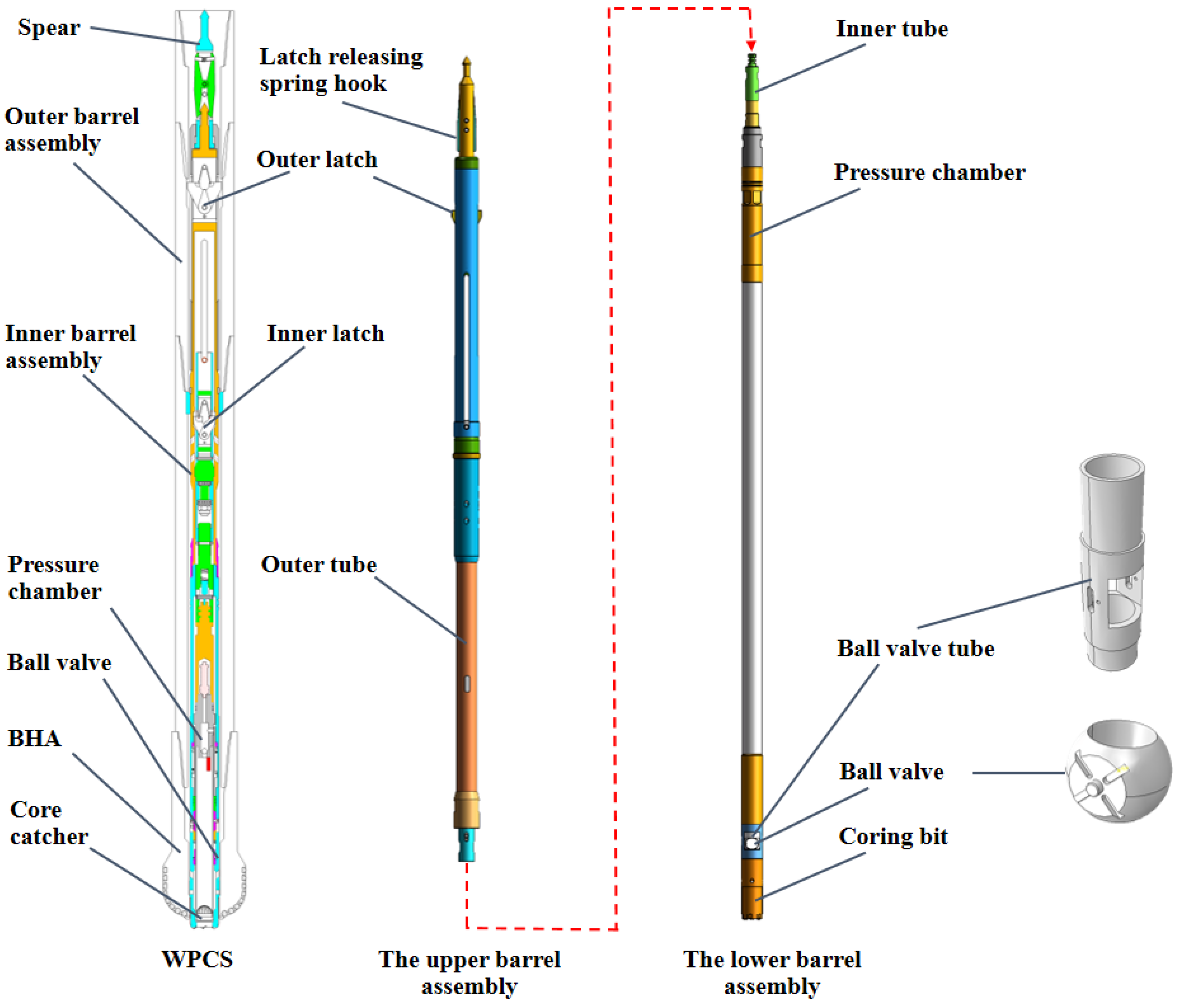
- The WPCS was designed as a rotary wireline coring system, similar to the Extended Coring System (ECS) for the drilling vessel JOIDES Resolution. It features a maximum outer diameter of 96 mm, compatible with 5-inch and 5½-inch drill strings to optimize operational efficiency. The pressure chamber within the WPCS sustains pressures up to 35 MPa (5000 psi). Core samples collected by the WPCS measure 2 inches in diameter, with a maximum length of 3.5 m [31,32].
- (2)
- In accordance with the gas hydrate phase equilibrium principles, the WPCS is designed to maintain in situ pressure upon retrieval from the formation. Post-recovery on deck, the pressure chamber is detached from the WPCS via a quick link system. This process controls temperature rise in the vertical cryogenic mousehole and facilitates connection to the newly designed Pressure Core Analysis Transfer System (PCATS) for pressure core transfer and analysis, ensuring pressure containment is maintained without release.
- (3)
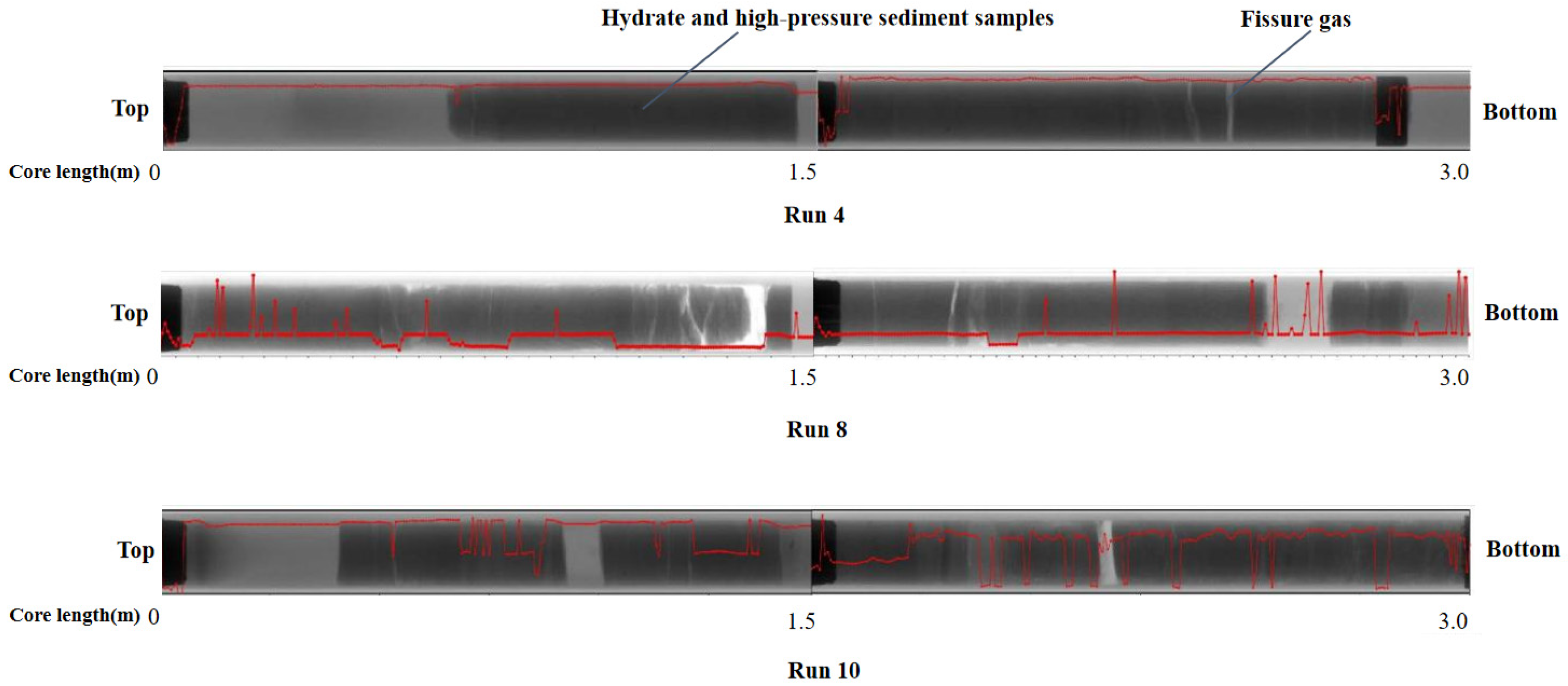
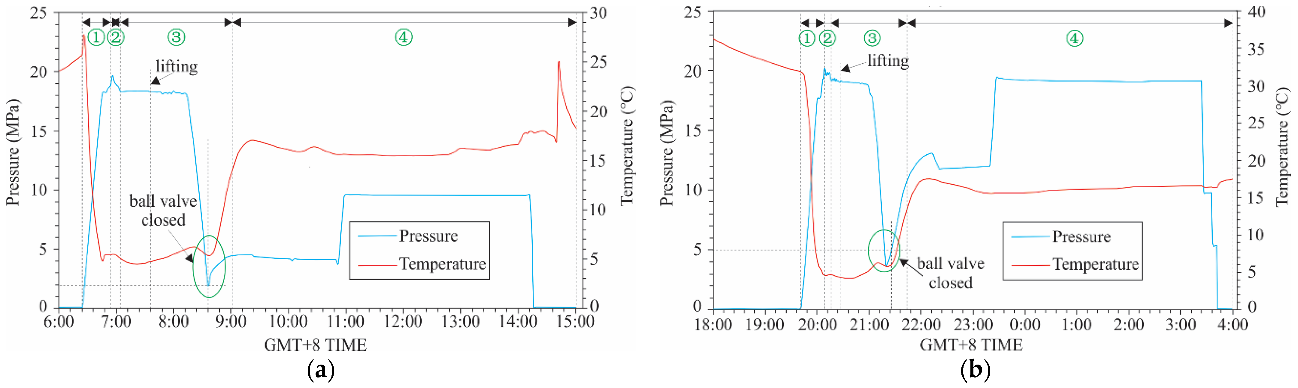
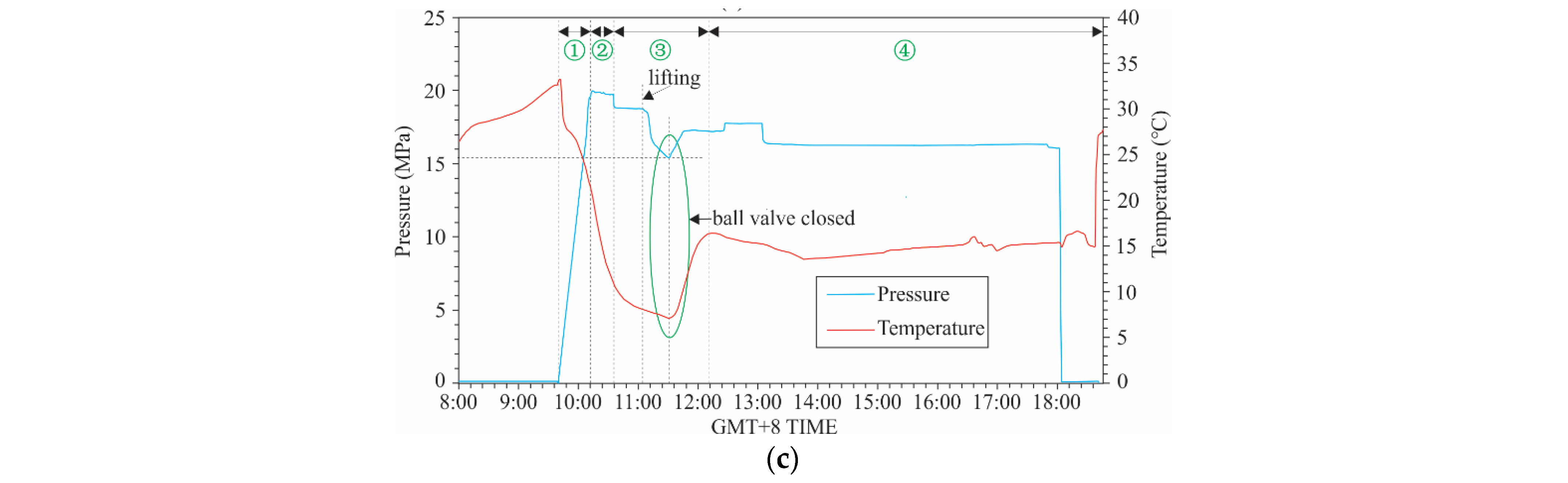
- Continuous monitoring of temperature and pressure profiles throughout the operation enables assessment of gas hydrate stability within the WPCS core, distinguishing between stable and dissolved states.
2.2. Working Mechanism
3. Application and Results

| Run | Hole | Water Depth (m) | Coring Depth (m) | Core Interval (m) | Recovery Rate (%) | Holding Pressure (MPa) | Reservoir Type | Remarks |
|---|---|---|---|---|---|---|---|---|
| 1 | Hole A | 1769.0 | 135.0–137.5 | 2.5 | 100 | 1.7 | Sandy gas hydrate layer and Clay layer | |
| 2 | Hole A | 1769.0 | 136.7–138.2 | 1.5 | 0 | 2 | Sandy gas hydrate layer | Sand plugging at the entrance of core tube |
| 3 | Hole A | 1769.0 | 138.2–139.7 | 1.5 | 0 | 10 | Sandy gas hydrate layer | Sand plugging at the entrance of core tube |
| 4 | Hole B | 1766.4 | 125.7–127.2 | 1.5 | 77 | 2.15 | Clay layer | |
| 5 | Hole B | 1766.4 | 130.8–133.3 | 2.5 | 87 | 0 | Sandy gas hydrate layer and Clay layer | BHA stuck and failed to retrieve |
| 6 | Hole B | 1766.4 | 132.5–133.3 | 0.8 | 0 | 0 | Sandy gas hydrate layer | Sand plugging at the entrance of core tube; Sand block at ball valve |
| 7 | Hole B | 1766.4 | 133.3–134.5 | 1.2 | 100 | 0 | Sandy gas hydrate layer and Clay layer | |
| 8 | Hole C | 1751.2 | 76.5–78.6 | 2.1 | 90 | 4 | Clay layer | |
| 9 | Hole C | 1751.2 | 95.7–97.8 | 2.1 | 52 | 4.6 | Clay layer | |
| 10 | Hole C | 1751.2 | 141.0–143.0 | 2.0 | 85 | 10 | Sandy gas hydrate layer and Clay layer | |
| 11 | Hole C | 1751.2 | 143.0–144.5 | 2.0 | 45 | 0 | Sandy gas hydrate layer | BHA stuck and failed to retrieve |
| 12 | Hole D | 1769.0 | 135.0–137.0 | 2.0 | 45 | 0 | Sandy gas hydrate layer | BHA stuck and failed to retrieve |
| 13 | Hole E | 1769.0 | 166.4–168.4 | 2.0 | 0 | 18.9 | Clay layer | |
| 14 | Hole F | 1769.0 | 126.0–127.5 | 1.5 | 0 | 17.8 | Sandy gas hydrate layer | Sand plugging at the entrance of core tube |
| 15 | Hole F | 1769.0 | 127.5–128.3 | 0.8 | 0 | 1.9 | Sandy gas hydrate layer | Sand plugging at the entrance of core tube |
4. Discussion
4.1. Factors Affecting Recovery Rate
4.2. Factors Affecting Pressure Holding
5. Conclusions
- (1)
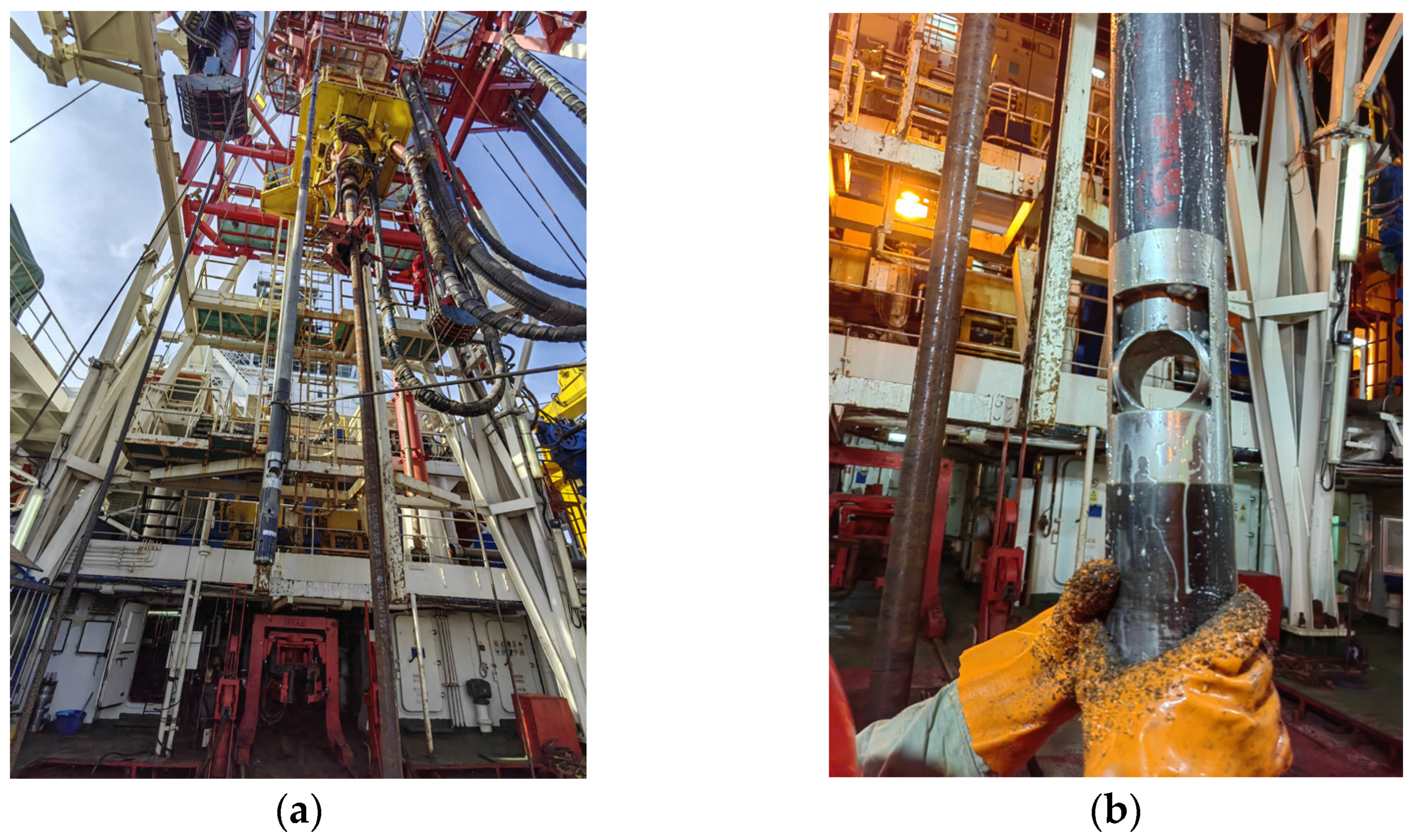
- A new WPCS core drilling tool was designed and applied for the first time in the deep sea during the hydrate survey voyage in the South China Sea of Guangzhou Marine Geological Survey, and good application results were obtained.
- (2)
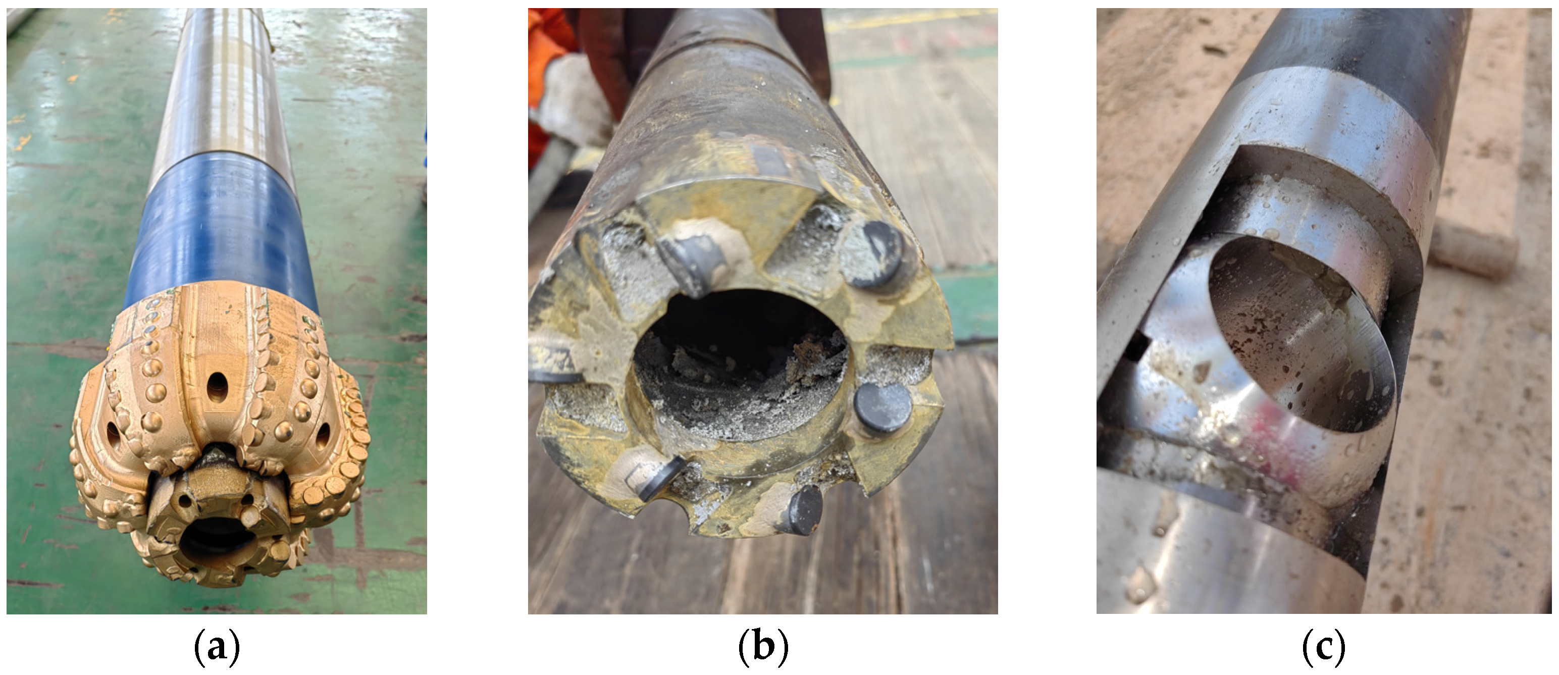
- The core recovery rate was closely related to the structure of the core drilling tool and hydrate formation. In the process of core drilling in the sandy hydrate formation, because the rock breaking surface of the drill tool was too large, the concentration of cuttings near the core bit was too high, which facilitated the complex situation of core pipe plugging, water hole plugging of the drill bit, and the interaction of the inner and outer pipes.
- (3)
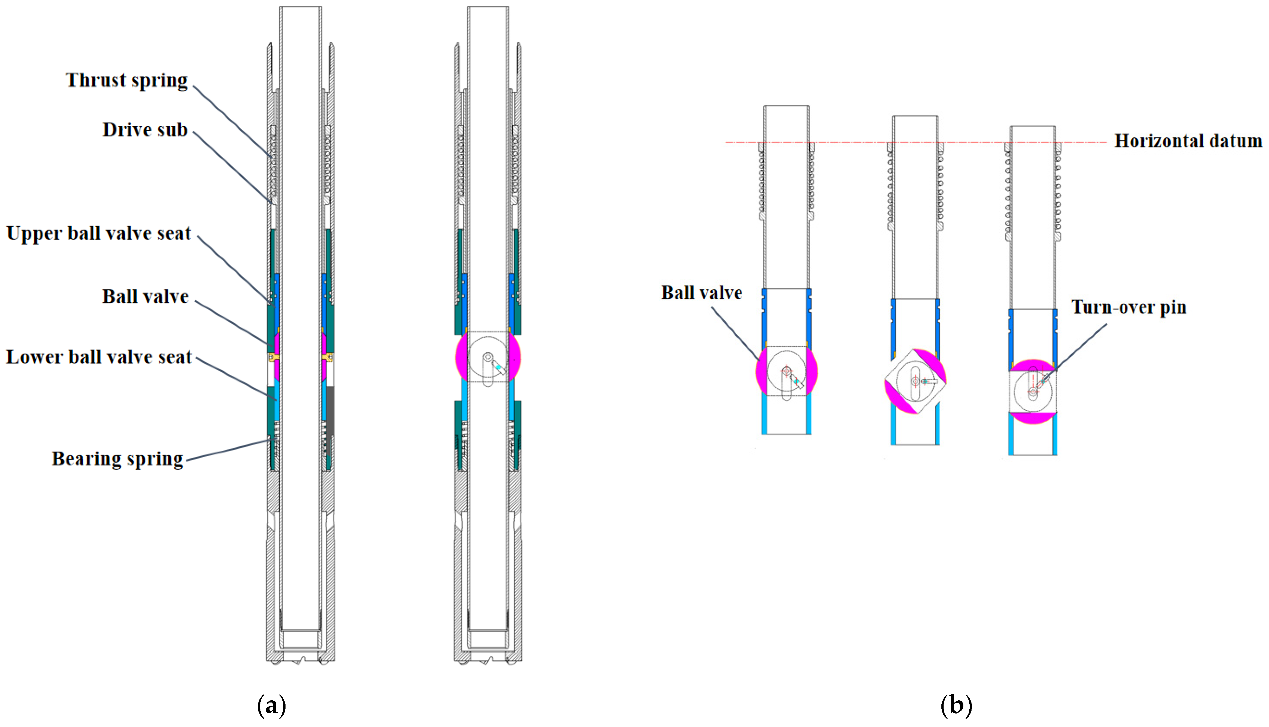
- The pressure-holding effect of the core drilling tool was related to the formation of hydrate, the sealing form of the ball valve, and the environmental pressure. Sandy hydrate formations often caused the ball valve to jam, while the muddy hydrate formation did not. The sealing form of the ball valve affected the effective driving force of the ball valve turning down, and the ambient pressure increased the friction resistance between the ball valve and the upper and lower ball valve seats.
- (4)
- In order to improve the application effect of WPCS, the coordination between WPCS and BHA should be further optimized. To maintain a clean and cool environment near the drill bit, the drilling fluid should be improved. In addition, the interaction between the drive spring and the environmental pressure should be quantified as much as possible.
- (5)
- Gas hydrates remain stable in a low-temperature and high-pressure environment. According to the phase equilibrium curve of gas hydrate, the main safety and security of WPCS operation is to control the temperature rising, to avoid pressure rising rapidly in the pressure chamber system of WPCS due to the pressure core dissolving.
- (6)
- The WPCS needs to develop abundant security measures to improve reliability, such as BHA being stuck and failing to retrieve.
6. Patents
Author Contributions
Funding
Institutional Review Board Statement
Informed Consent Statement
Data Availability Statement
Acknowledgments
Conflicts of Interest
Abbreviations
| BHA | Bottom hole assembly |
| CNOOC | China National Offshore Oil Corporation |
| DMU | Downward motion unit |
| ECS | Extended coring system |
| FPC | Fugro pressure corer |
| FRPC | Fugro rotary pressure corer |
| GMGS | Guangzhou Marine Geological Survey |
| HRC | HYACE rotary corer |
| HYACE | Hydrate autoclave coring equipment |
| ODP | Ocean drilling program |
| PCATS | Pressure core analysis and transfer system |
| PCTB | Pressure corer tool ball valve |
| PTCS | Pressure temperature core sampler |
| PCS | Pressure core sampler |
| WPCS | Wireline pressure coring system |
References
- Kvenvolden, K.A. Hydrocarbon gas in sediment of the Southern Pacific Ocean. Geo Mar. Lett. 1988, 8, 179–187. [Google Scholar] [CrossRef]
- Kvenvolden, K.A. Methane hydrates and global climate. Glob. Biogeochem. Cycles 1988, 2, 221–229. [Google Scholar] [CrossRef]
- Bazaluk, O.; Sai, K.; Lozynskyi, V.; Petlovanyi, M.; Saik, P. Research into Dissociation Zones of Gas Hydrate Deposits with a Heterogeneous Structure in the Black Sea. Energies 2021, 14, 1345. [Google Scholar] [CrossRef]
- Brewer, P.G.; Orr, F.M.; Friederich, G.; Kvenvolden, K.A.; Orange, D.L. Gas Hydrate Formation in the Deep Sea: In Situ Experiments with Controlled Release of Methane, Natural Gas, and Carbon Dioxide. Energy Fuels 1998, 12, 183–188. [Google Scholar] [CrossRef]
- Kvenvolden, K.A. Methane hydrate—A major reservoir of carbon in the shallow geosphere? Chem. Geol. 1988, 71, 41–51. [Google Scholar] [CrossRef]
- Kvenvolden, K.A. Potential effects of gas hydrate on human welfare. Proc. Natl. Acad. Sci. USA 1999, 96, 3420–3426. [Google Scholar] [CrossRef] [PubMed]
- Koh, C.A.; Sloan, E.D.; Sum, A.K.; Wu, D.T. Fundamentals and Applications of Gas Hydrates. Annu. Rev. Chem. Biomol. Eng. 2011, 2, 237–257. [Google Scholar] [CrossRef] [PubMed]
- Kvenvolden, K.A. Gas hydrates as a potential energy resource—A review of their methane content. US Geol. Surv. Prof. Pap. 1993, 1570, 555–561. [Google Scholar]
- Lin, Z.; Su, M.; Zhou, H.; Su, P.; Liang, J.; Wang, F.; Yang, C.; Luo, K. Deposition processes of gas hydrate-bearing sediments in the inter-canyon area of Shenhu Area in the northern South China Sea. J. Oceanol. Limnol. 2023, 41, 740–756. [Google Scholar] [CrossRef]
- Hou, L.; Yang, J.; Liu, Z.; Jiao, J. Current status and suggestions on development of marine gas hydrate technologies in China. World Pet. Ind. 2021, 28, 17–22. [Google Scholar]
- Klymenko, V.; Ovetskyi, S.; Martynenko, V.; Vytiaz, O.; Uhrynovskyi, A. An alternative method of methane production from deposits of subaquatic gas hydrates. Min. Miner. Depos. 2022, 16, 11–17. [Google Scholar] [CrossRef]
- Ye, J.; Qin, X.; Xie, W.; Lu, H.; Ma, B.; Qiu, H.; Liang, J.; Lu, J.; Kuang, Z.; Lu, C.; et al. The second natural gas hydrate production test in the South China Sea. China Geol. 2020, 3, 197–209. [Google Scholar] [CrossRef]
- Abid, K.; Spagnoli, G.; Teodoriu, C.; Falcone, G. Review of pressure coring systems for offshore gas hydrates research. Underw. Technol. 2015, 33, 19–30. [Google Scholar] [CrossRef]
- Sun, J.; Ning, F.; Lei, H.; Gai, X.; Sanchez, M.; Lu, J.; Li, Y.; Liu, L.; Liu, C.; Wu, N.; et al. Wellbore stability analysis during drilling through marine gas hydrate-bearing sediments in Shenhu area: A case study. J. Pet. Sci. Eng. 2018, 170, 345–367. [Google Scholar] [CrossRef]
- Li, X.; Xie, W.; Liu, A.; Yu, Y.; Xiong, L.; Yu, P.; Xiong, Z.; Feng, X.; Cui, S.; Zeng, J. New Research of Borehole Wall Protection Technology in Ocean Scientific Drilling. Mar. Technol. Soc. J. 2023, 57, 72–87. [Google Scholar] [CrossRef]
- Schultheiss, P.J.; Francis, T.J.G.; Holland, M.; Roberts, J.A.; Amann, H.; Parkes, R.J.; Martin, D.; Rothfuss, M.; Tyunder, F.; Jackson, P.D. Presure coring, logging and subsampling with the HYACINTH system. Geol. Soc. Lond. Spec. Publ. 2006, 267, 151–163. [Google Scholar] [CrossRef]
- Liu, X.; Ruan, H.; Zhao, Y.; Cai, J.; Chen, Y.; Liang, T.; Li, C.; Liu, H.; Deng, D. Progress in research and application of the pressure-temperature core sampler for marine natural gas hydrate. Drill. Eng. 2021, 48, 33–39. [Google Scholar] [CrossRef]
- Schultheiss, P.J.; Aumann, J.T.; Humphrey, G.D. Special session-gas hydrates: Pressure coring and pressure core analysis developments for the upcoming Gulf of Mexico Joint Industry Project Coring Expedition. In Proceedings of the Offshore Technology Conference, Houston, TX, USA, 3–6 May 2010. [Google Scholar]
- Abegg, F.; Hohnberg, H.J.; Paper, T.; Bohrmann, G.; Freitag, J. Development and application of pressure-core-sampling systems for investigation of gas- and gas-hydrate-bearing sediments. Deep Sea Res. Part I Ocean. Res. Pap. 2008, 55, 1590–1599. [Google Scholar] [CrossRef]
- Kubo, Y.; Mizuguchi, Y.; Inagaki, F.; Yamamoto, K.; Schultheiss, P.; Grigar, K. A new hybrid pressure coring system for the drilling vessel Chikyu. Proc. Integr. Ocean Drill. Program 2014, 17, 37–43. [Google Scholar] [CrossRef]
- Holland, M.E.; Schultheiss, P.J.; Roberts, J.A. Gas hydrate saturation and morphology from analysis of pressure cores acquired in the Bay of Bengal during expedition NGHP-02, offshore India. Mar. Pet. Geol. 2019, 108, 407–423. [Google Scholar] [CrossRef]
- Lee, Y.J. Gas Hydrate Exploration by using PCS (Pressre Core Sampler): ODP Leg 204. Econ. Environ. Geol. 2005, 38, 165–176. [Google Scholar]
- Heeschen, K.U.; Hohnberg, H.J.; Haeckel, M.; Abegg, F.; Drews, M.; Bohrmann, G. In situ hydrocarbon concentrations from pressurized cores in surface sediments, Northern Gulf of Mexico. Mar. Chem. 2007, 107, 498–515. [Google Scholar] [CrossRef]
- Inada, N.; Yamamoto, K. Data report: Hybrid Pressure Coring System tool review and summary of recovery result from gas-hydrate related coring in the Nankai Project. Mar. Pet. Geol. 2015, 66, 323–345. [Google Scholar] [CrossRef]
- Guo, D.; Xie, H.; Chen, L.; Zhou, Z.; Lu, H.; Dai, L.; Wang, D.; Wang, T.; Li, J.; He, Z.; et al. In-situ pressure-preserved coring for deep exploration: Insight into the rotation behavior of the valve cover of a pressure controller. Pet. Sci. 2023, 4, 2386–2398. [Google Scholar] [CrossRef]
- Yamamoto, K.; Inada, N.; Kubo, S.; Fujii, T.; Suzuki, K.; Nakatsuka, Y.; Ikawa, T.; Seki, M.; Konno, Y.; Yoneda, J.; et al. A Pressure Coring Operation and On-board Analyses of Methane Hydrate-bearing Samples. In Proceedings of the Offshore Technology Conference 2014, OTC 2014, Houston, TX, USA, 5–8 May 2014. [Google Scholar]
- Guo, D.; Xie, H.; Gao, M.; Li, J.; He, Z.; Chen, L.; Li, C.; Zhao, L.; Wang, D.; Zhang, Y.; et al. In-situ pressure-preserved coring for deep oil and gas exploration: Design scheme for a coring tool and research on the in-situ pressure-preserving mechanism. Energy 2024, 286, 129519. [Google Scholar] [CrossRef]
- Humphrey, G.; Holland, M.; Schultheiss, P. Wireline Coring and Analysis under Pressure: Recent Use and Future Developments of the HYACINTH System. Sci. Drill. 2009, 7, 44–50. [Google Scholar] [CrossRef]
- Freudenthal, T.; Wefer, G. Drilling cores on the sea floor with the remote-controlled sea floor drilling rig MeBo. Geosci. Instrum. Methods Data Syst. 2013, 2, 329–337. [Google Scholar] [CrossRef]
- Dickens, G.R.; Wallace, P.J.; Paull, C.K.; Borowski, W.S. Detection of methane gas hydrate in the pressure core sampler (PCS): Volume-pressure-time relations during controlled degassing experiments. Proc. Ocean Drill. Program Sci. Results 2020, 164, 113–126. [Google Scholar] [CrossRef]
- Li, X.; Li, K.; Zhang, Y.; Wang, Z.; Shi, S. Development of Marine Gas-hydrate Pressure and Temperature Core Sampler. Drill. Prod. Technol. 2021, 44, 72–75. [Google Scholar]
- Li, X.; Xiong, L.; Xie, W.; Gao, K.; Shao, Y.; Chen, Y.; Yu, Y.; Kou, B.; Lu, Q.; Zeng, J.; et al. Design and Experimental Study of Core Bit for Hard. Rock Drilling in Deep-Sea. J. Mar. Sci. Eng. 2023, 11, 306. [Google Scholar] [CrossRef]
- Lu, C.; Zhang, T.; Xu, J.; Qiao, M.; Blinov, P.A.; Zhang, S.; Merzliakov, M.U. Development and experiment of pressure core sampler for marine natural gas hydrates. Drill. Eng. 2023, 50, 18–26. [Google Scholar]
- Li, W. Design and Finite Element Analysis of Pressure Maintaining Coring Ball Valve. Sci. Technol. Innov. 2023, 12, 1–4. [Google Scholar]


| Number of Cores | ||
| Hybrid PCS cores | 16 × 3 m + 2 × 1.5 m | |
| Recovery rate | ||
| Hybrid PCS | 34.99/51 m, recovery rate 69% | |
| Pressure condition | ||
| Pressure-conserved cores (≥12 MPa) | 8 cores | 17.08 m |
| Partially pressure-conserved cores (≥5.5 MPa) | 4 cores | 11.6 m |
| Pressure lost (<5.5 MPa) | 6 cores | 6.31 m |
| Drill Pipe Diameter (in) | Core OD (in) | Max Core Length (m) | Max Pressure (MPa) | Sealing Mechanism | Active | |
|---|---|---|---|---|---|---|
| PCS | 5 or 51/2 | 1.575 | 1 | 69 | ball valve | No |
| FPC | 2.125 | 1 | 25 | flapper valve | No | |
| HRC | 2 | 1 | 21 | flapper valve | No | |
| PTCS | 65/8 | 2.625 | 3.5 | 24 | ball valve | No |
| Hybrid PCS/PCTB | 5 or 51/2 | 2 | 3.5 | 35 | ball valve | Yes |
Disclaimer/Publisher’s Note: The statements, opinions and data contained in all publications are solely those of the individual author(s) and contributor(s) and not of MDPI and/or the editor(s). MDPI and/or the editor(s) disclaim responsibility for any injury to people or property resulting from any ideas, methods, instructions or products referred to in the content. |
© 2024 by the authors. Licensee MDPI, Basel, Switzerland. This article is an open access article distributed under the terms and conditions of the Creative Commons Attribution (CC BY) license (https://creativecommons.org/licenses/by/4.0/).
Share and Cite
Lu, Q.; Qin, R.; Yu, Y.; Qi, L.; Xie, W.; Lu, H.; Xu, B.; Shi, H.; Xu, C.; Li, X. The Design and Application of a New Wireline Pressure Coring System for the Guangzhou Marine Geological Survey Methane Hydrate Expedition in the South China Sea. Appl. Sci. 2024, 14, 6753. https://doi.org/10.3390/app14156753
Lu Q, Qin R, Yu Y, Qi L, Xie W, Lu H, Xu B, Shi H, Xu C, Li X. The Design and Application of a New Wireline Pressure Coring System for the Guangzhou Marine Geological Survey Methane Hydrate Expedition in the South China Sea. Applied Sciences. 2024; 14(15):6753. https://doi.org/10.3390/app14156753
Chicago/Turabian StyleLu, Qiuping, Rulei Qin, Yanjiang Yu, Liqiang Qi, Wenwei Xie, Hongfeng Lu, Benchong Xu, Haoxian Shi, Chenlu Xu, and Xingchen Li. 2024. "The Design and Application of a New Wireline Pressure Coring System for the Guangzhou Marine Geological Survey Methane Hydrate Expedition in the South China Sea" Applied Sciences 14, no. 15: 6753. https://doi.org/10.3390/app14156753