Article

Design and Implementation of a MIMO Integral Resonant Control for Active Vibration Control of Pedestrian Structures

1
Department of Signal Processing and Communications, Universidad de Alcalá, 28805 Alcalá de Henares, Spain
2
School of Civil Engineering, Zhengzhou University, Zhengzhou 450001, China
3
Department of Continuos Media and Structure Theory, Universidad Politécnica de Madrid, 28040 Madrid, Spain
4
Artificial Intelligence, Robotics and Mechatronic Systems Group (ARMS), School of Engineering, University of Aberdeen, Aberdeen AB24 3UE, UK
*
Author to whom correspondence should be addressed.
Appl. Sci. 2024, 14(15), 6784; https://doi.org/10.3390/app14156784 (registering DOI)
Submission received: 9 July 2024 / Revised: 30 July 2024 / Accepted: 31 July 2024 / Published: 3 August 2024
(This article belongs to the Special Issue Vibration Problems in Engineering Science)

Abstract

:
In contemporary construction, the prevalence of vibration serviceability issues in lightweight and slender structures has become increasingly common, owing to advancements in building materials and construction methods. While these structures often meet the criteria for ultimate limit states, they can still elicit complaints due to excessive vibrations induced by human activity. To address this challenge, the integral resonant control (IRC) technique has emerged as a favored approach for actively damping vibrations in various systems. This study introduces a fresh perspective by proposing the implementation of a multi-input multi-output (MIMO) IRC scheme for active vibration control (AVC) specifically tailored for pedestrian structures utilizing inertial mass actuators. This application of MIMO IRC for AVC represents a novel advancement in the field, offering a new solution to address vibration issues in lightweight and slender structures. Building upon a common framework and design methodology outlined in previous research, this work presents a novel application of MIMO IRC for AVC. The designed controller undergoes rigorous testing and is implemented on a laboratory floor structure to validate its efficacy. The outcomes of this study demonstrate the effectiveness of the proposed MIMO IRC scheme in actively damping vibrations, thereby enhancing the serviceability and comfort levels of lightweight and slender structures subjected to human-induced excitations.

1. Introduction

Improvements in the design and construction of civil structures have led to the development of lighter and more slender floor structures, meeting the criteria for ultimate limit states. However, these advancements have also rendered these structures increasingly susceptible to vibrations induced by human activity [1,2]. Pedestrian-induced vibrations, in particular, pose a significant challenge to the serviceability of buildings, as they can cause occupant discomfort and potentially disrupt sensitive equipment [3]. Addressing these issues often involves costly solutions. Recent research has explored various approaches to evaluate and mitigate pedestrian-induced vibrations. For instance, Bouzari et al. [3] proposed short-term assessments and controlled tests as alternatives to long-term monitoring for assessing serviceability. Additionally, Wang et al. [4] utilized accurate finite-element (FE) modeling methods to evaluate the serviceability of suspended floors under human-induced excitation. These studies contribute to the understanding of how pedestrian-induced vibrations affect building performance and offer insights into potential mitigation strategies.
The solutions for addressing human-induced vibrations can be categorized into passive, semi-active, and active control techniques, as outlined in the state-of-the-art literature [5,6]. Passive vibration control (PVC) methods, particularly employing tuned mass dampers (TMDs), have garnered significant attention for mitigating resonance issues within specific frequency ranges. TMDs are favored for their energy efficiency and low maintenance costs [7,8,9]. Several researchers have explored innovative applications of TMD systems, such as utilizing multiple TMDs to address vibrations across different frequency bands [10]. For instance, Wang et al. [10] developed a multiple TMD system designed to mitigate vibrations induced by walking, running, and jumping activities, each with distinct frequency characteristics. The effectiveness of TMD systems in mitigating vibrations has led to a growing research interest in this area, as evidenced by recent studies like Xie et al. [11]. Xie et al. [11] investigated vibration control in long-span steel pedestrian corridors subjected to crowd-induced vibrations, employing a combination of field measurements and numerical simulations. Specifically, the study conducted field modal tests on a multi-tower structure’s steel corridor and analyzed the acceleration response to pedestrian traffic. Li et al. [12] provided recommended parameters for the transverse vibration reduction design of long-span pedestrian arch bridges by setting TMDs on both the arch ribs and the bridge deck. The findings demonstrate the efficacy of a tuned mass damper (TMD) system in effectively managing vibrations induced by pedestrian activities.
Various passive techniques offer advantages over traditional TMDs in addressing human-induced vibrations. For instance, Wen et al. [13] developed a hybrid control scheme incorporating steel braces and eddy current tuned mass dampers to enhance structural stiffness and damping ratios, respectively, in controlling human-induced vibrations on road bridges. Zhou et al. [14] introduced a band gap in footbridges and proposed a novel technique using inerter-based dynamic vibration absorbers. Liu et al. [15] proposed a modified damper based on a vertical tuned liquid column gas damper to mitigate excessive floor vibrations induced by human walking. Despite the advantages of passive techniques, they face challenges in maintaining optimal performance when dealing with structures exhibiting fluctuating modal parameters or excitation at varying frequency ranges. In such cases, semi-active techniques, capable of adjusting mass, damping, or stiffness, are commonly employed [16,17,18]. However, for lower vibration levels typical of human activity, including non-resonant excitations, passive or semi-active TMDs may exhibit dead zones, limiting their effectiveness in service [19].
The limitations of passive and semi-active techniques have prompted a growing interest in active vibration control (AVC) methodologies [20]. The state of the art [20] emphasizes the need for these AVC algorithms to be robust, versatile, and easy to implement, while allowing for flexible performance goal setting. Thus, AVC can offer the advantage of adaptability to varying excitation frequencies and modal parameters, potentially providing more effective solutions for mitigating structural vibrations.
The actuators used in AVC can be rotor dampers [21], pneumatic muscle actuators [22], or inertial mass dampers [23], among others. In [21], a Twin Rotor Damper (TRD) was used, which is an active mass damper with two rotating masses, designed to mitigate vibrations on footbridges caused by human activity. A prototype of this system has been successfully implemented on a narrow steel footbridge that was prone to such vibrations, demonstrating the TRD’s effectiveness in a practical setting. In [22], a Delayed Modal Velocity Feedback Control strategy, which was based on a modal state-space model derived from the bridge, is proposed. The method’s effectiveness was demonstrated through experiments that successfully controlled the bridge’s vertical resonance modes. In [23], an active tuned mass damper (ATMD) system based on the Linear Quadratic Gaussian (LQG) approach is proposed. This work concluded that AVC can significantly control both non-resonant structural responses and resonant vibrations.
In the literature, there are more examples of AVC implementation with inertial mass actuators [20]. However, a significant challenge arises from the potential instability associated with introducing active control forces, which can destabilize the closed control loop with severe consequences [19]. Instability issues often stem from inadequate consideration of actuator dynamics in controller design [24,25]. Strategies to mitigate instability include accounting for spillover effects under residual modes through careful placement of actuators and sensors. Recent advancements, such as those in [26], have improved stability margins by approximating the inversion of actuator dynamics. Additionally, an independent modal space design process for active control of floor vibrations induced by human impact excitation has been developed. In [27], a method for controlling floor vibrations caused by human activity, using a system that independently controls each mode of vibration, is presented. It incorporates a phase–lead compensator to improve stability and damping and considers the potential for spillover effects when placing actuators and sensors. The method’s effectiveness in reducing vibrations was confirmed through experiments with a steel plate. Other practical issues of these actuators are the force and stroke saturation, which must be considered in the design. In [28], a novel velocity feedback control strategy is proposed to prevent the stroke saturation of inertial actuators by incorporating inner loops into a direct velocity feedback (DVF) control system.
While SISO AVC systems are commonly used, for specific applications, multi-input multiple-output (MIMO) AVC schemes have been proposed. In Hanagan et al. [29], the problem of the DVF MIMO controller was introduced to improve the results of the SISO ones. In [30], the work of [29] was improved upon by incorporating input–output frequency weighting to enhance performance and robustness. The work [31] compares three types of control systems used in engineering: direct velocity feedback, observer-based, and independent modal space controllers. These systems were analyzed based on their implementation in SISO and MIMO configurations. The advantages of using MIMO AVC in human-induced vibration are better shown in [32]. The simulation results illustrate how an optimized MIMO AVC can improve the vibration levels in real complex structures with a large number of vibration modes and a large number of test points. Another MIMO applications is [33], where an optimal fractional-order PID control design for time-delayed multi-input multi-output seismic-excited structural system is proposed.
Considering the recommendations of [20], where an active vibration controller should be versatile, and easy to implement, the proposed work extends the utilization of SISO integral resonant control (IRC), originally introduced in [34], to a MIMO IRC configuration. Based on the foundational framework outlined in [35] and the MIMO IRC proposed in [36], this paper contributes with a new application of a MIMO IRC controller capable of mitigating spillover effects more effectively compared to prior efforts, such as those detailed in [30].
This research unfolds through distinct stages: first is the identification of the floor structure parametric model and the controller structure (Section 2), followed by the determination of the optimal actuator placement and control parameters for MIMO IRC utilizing the proposed common framework (Section 3); subsequently, the presentation of experimental findings is given (Section 4); finally, conclusions and avenues for future research are given (Section 5).

2. System Modeling and Control Structure

This section first provides the theoretical details of the parametric model employed to capture the system dynamics to be controlled. This is followed by an introduction to the theoretical structure of the MIMO IRC scheme proposed.

2.1. Parametric System Model

The standard state-space representation for a typical flexible structure, which comprises n vibration modes and p nodes (i.e., possible locations for actuators/sensors and perturbations), is given by:
x ˙ s = A s x s + B s u u + B s w w , y = C s x s + D s u u + D s w w ,
where u represents the control input vector (i.e., the force imparted by the actuators), w denotes the perturbation forces, and y is the output vector (sensor measurements, typically acceleration). The matrices A s , B s u , B s w , C s , D s u , and D s w define the state-space model of the structure. When (1) is expressed in modal coordinates, these state-space matrices can be explicitly written as follows [37]:
A s = 0 I Ω 2 2 Z Ω , B s u = B s w = 0 Φ , C s = Ω 2 Φ T 2 Z Ω Φ T , D s u = D s w = Φ Φ T ,
where Ω and Z are diagonal matrices formed by the natural frequencies ( [ ω 1 , , ω n ] ) and damping ratios ( [ ξ 1 , , ξ n ] ), respectively, and Φ is an n × p matrix. Note that each kth column is formed by the kth vibration mode shape. The state vector is defined as x s = [ x s 1 , , x s n , x ˙ s 1 , , x ˙ s n ] , where [ x s 1 , , x s n ] are the modal coordinates of the structure and [ x ˙ s 1 , , x ˙ s n ] are their derivatives.
The time domain system of Equations (1) and (2) can be transformed into a frequency domain transfer function matrix relationship, given by:
Y ( s ) = G m ( s ) U ( s ) + W ( s ) ,
where G m ( s ) = C s s I A s 1 B s u + D s u .
In this work, inertial mass actuators that generate force by accelerating an inertial mass are utilized. These actuators consist of an inertial (or moving) mass attached to a current-carrying coil, moving in a magnetic field. If q actuators are used, the q × q matrix of the actuator linear part can be written as:
G A ( s ) = G A , 1 ( s ) 0 0 G A , q ( s ) ,
where each transfer function G A , i ( s ) is defined as:
G A , i ( s ) = g A , i s 2 ( s 2 + 2 ξ A , i ω A , i s + ω A , i 2 ) ϵ ( s + ϵ ) .
Here, g A , i > 0 is the actuator gain parameter, ξ A , i is the damping ratio, ω A , i is the natural frequency of the actuator placed at the i th node, and ϵ models the amplifier dynamics in voltage mode (see [38] for more information).
With the system model in place, the next section will present the detailed control design of the MIMO IRC scheme employed to demonstrate the superior damping of pedestrian-induced vibrations on a lab-scale civil structure.

2.2. Proposed Control Scheme

The general control scheme is depicted in Figure 1, illustrating two primary components. The first component encompasses the dynamics of the flexible structure, represented by G m ( s ) (see Equations (1)–(3)). The second component constitutes the AVC system, denoted as K m ( s ) . This therm comprises the shakers’ dynamics, denoted as G A ( s ) (see Equation (5)), and the controller dynamics, denoted as K ( s ) . In addition, there are the output of the shakers ( U ( s ) ), the perturbations ( U ( s ) ), which in this work will be the shakers (open loop) and a large-sled impulse hammer (closed loop), the accelerometers’ outputs ( Y ( s ) ), the control voltage of the shaker amplifiers ( V ( s ) ), and the control reference ( R ), which in this application is zero. This representation delineates the interplay between the structure’s inherent dynamics and the active vibration control system, emphasizing their integral roles in mitigating vibrations and enhancing structural performance.
The MIMO AVC system, represented by the transfer function G m ( s ) , embodies multiple IRC units. The IRC controller, initially introduced in [39], stands out as a straightforward, robust, and highly effective method for managing vibrations in intelligent structures equipped with sensors and actuators collocated in proximity. Renowned for its versatility, this controller has found wide application across diverse domains, showcasing its prowess in real-world scenarios such as damping oscillations in automobiles [40] and controlling vibrations in wind turbines [41].
Originating from its single-input single-output (SISO) variant proposed for human-induced vibrations in [34], the IRC framework has evolved to accommodate the complexities of MIMO systems. In the pioneering work of [36], the adaptation to the MIMO domain was introduced, where adjustments were made to incorporate direct feed-through elements into the collocated system, thus furnishing a comprehensive MIMO version of the IRC controller. This extension not only broadened the applicability of the IRC technique, but also enhanced its efficacy in addressing complex multivariable vibration control challenges, marking a significant advancement in the field. This extension was configured in the MIMO version as the following q × q diagonal matrix:
K ( s ) = K 1 ( s ) 0 0 K q ( s ) ,
where K i ( s ) = γ i / ( s d i γ i ) is the IRC configured for node i. In this specific instance of MIMO IRC, it is important to note that only the acceleration measured at the node where the actuator is positioned is considered. Similar to the SISO case [34], controller stability can be achieved as the phase of each transfer function K i ( s ) G A , i ( s ) begins at 180 degrees. Notably, the actuator features two zeros at the origin, steadily decreasing until reaching −180 degrees. It is worth mentioning that a forthcoming study will address the formal demonstration of stability. This observation underscores the robustness of the MIMO IRC approach in effectively mitigating vibrations and enhancing the structural performance, thereby laying the groundwork for further advancements and insights in the field of active vibration control.
With the theoretical control design explained, the next section presents the detailed design of the MIMO IRC scheme within the common framework established. The employed performance indices chosen to quantify closed-loop performance, as well as the control parameter optimization results are also presented.

3. Design Methodology Based on the Common Framework

The design methodology consists of the following:
  • Identifications and finite-element (FE) model calibration;
  • Define the performance index (PI);
  • Define the strategy to find the optimal controller;
  • Obtain the optimal controller.

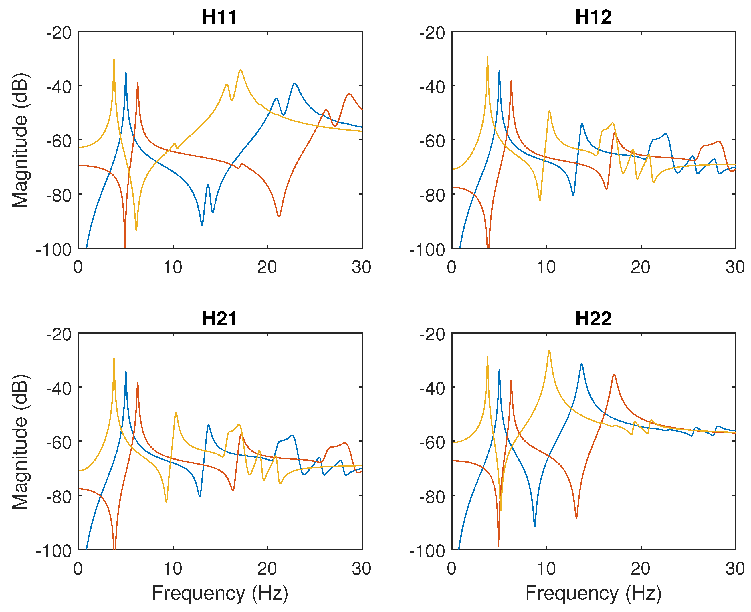
3.1. Identifications and FE Model Calibration
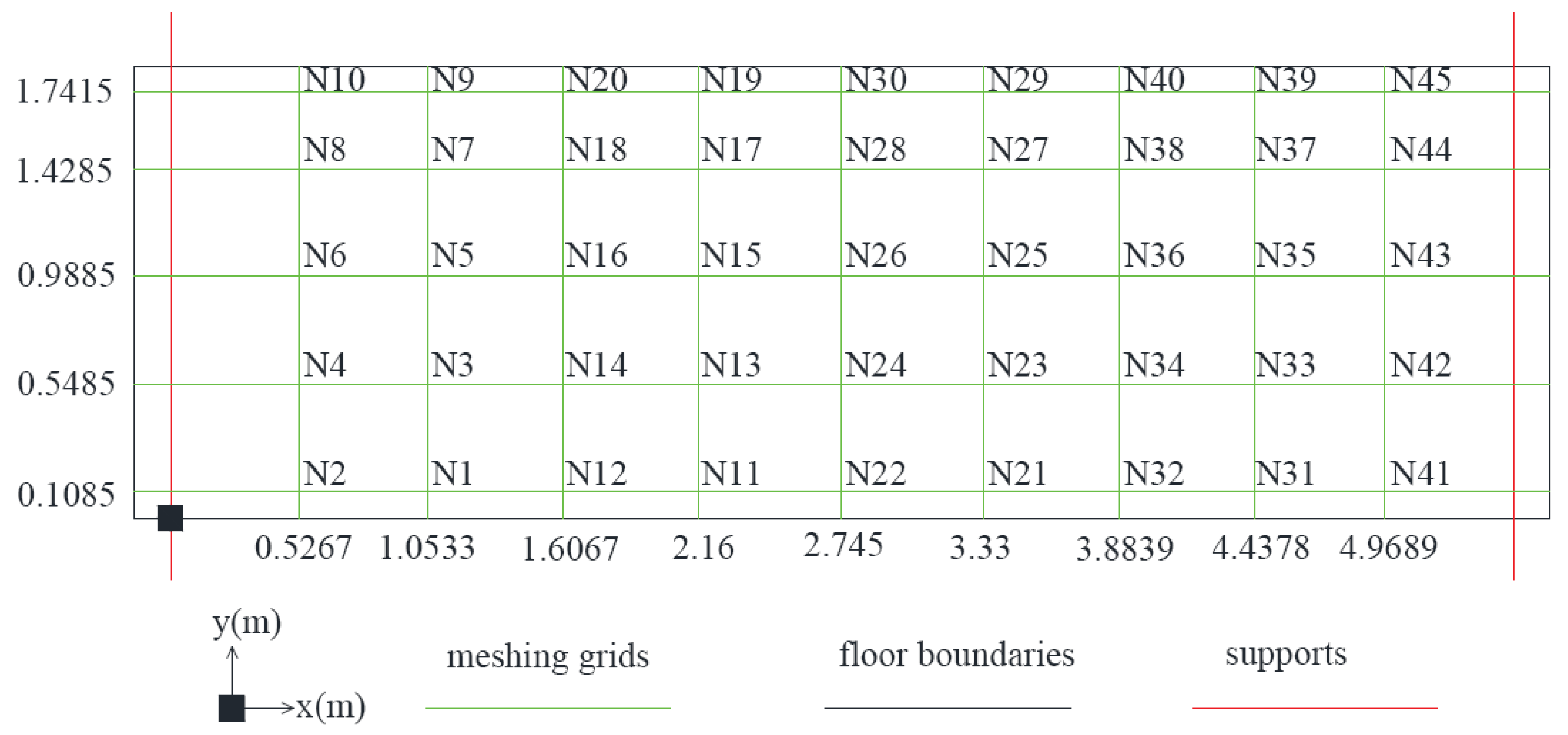
The experimental results were conducted on a full-scale laboratory structure, as depicted in Figure 2. This structure comprises a slender steel–concrete composite slab with dimensions of 5.8 m × 1.8 m × 0.14 m, resulting in a thickness-to-span ratio of only 1/40. The control of this structure was achieved using two APS electrodynamic actuators, driven by two power amplifiers (APS 144 and APS 145, APS Dynamics, Inc., Sand Diego, CA, USA). Acceleration measurements were performed utilizing a piezoelectric accelerometer (PCB Piezotronics model 393B31, PCB Piezotronics GmbH, Huckelhoven, Germany). To induce excitations and obtain the experimental frequency response functions (FRFs), a large-sledge impulse hammer (PCB model 086D50, PCB Piezotronics GmbH, Huckelhoven, Germany) was employed. This experimental setup enables comprehensive investigation and analysis of the structural response under controlled conditions, providing valuable insights into the efficacy of the proposed active vibration control strategies.
To commence, a finite-element (FE) model was constructed using ANSYS Multiphysics 2022R2 [42], employing shell elements and encompassing 45 nodes (refer to Figure 3). This FE model serves as the basis for selecting appropriate actuator locations capable of mitigating the most dominant vibration modes. Consequently, the actuators and accelerometers were strategically positioned at nodes N16 and N22 to control and measure the first vibration modes (see Figure 3 and Figure 4).
Figure 4 illustrates the mode shapes of the first three vibration modes, consisting of two bending modes and one torsional mode. These mode shapes aid in identifying suitable actuator locations for effectively canceling the most significant vibration modes. Notably, the hammer is utilized at node N12, identified as an optimal location for exciting all vibration modes uniformly. This meticulous approach ensures that the experimental setup is finely tuned to capture and address the dominant dynamics of the structure, facilitating accurate assessment and validation of the active vibration control strategies proposed in the study.
The next step is to identify the structure and actuators. The actuators used in this word were inertial mass actuators (also known as proof-mass actuators), which generate forces through the acceleration of an inertial mass on the structure on which they are placed. The actuator consists of an inertial (or moving) mass (denoted as m A ) attached to a current-carrying coil moving in a magnetic field created by an array of permanent magnets. The inertial mass is connected to the frame by a suspension system, modeled by a spring stiffness k A and a viscous damping c A [38] (see Figure 5).
The actuator parameters identified in Equation (5)) are obtained by configuring the actuator and its amplifier to operate in voltage mode. The parameters within Equation (5)) have been meticulously tuned to align the 3rd-order transfer function with the empirical data presented in Figure 6:
  • N16: g A , 1 = 145 , ξ A , 1 = 0.55 , ω A , 1 = 11.3 rad/s and ϵ 1 = 62.8 ;
  • N22: g A , 2 = 180 , ξ A , 2 = 0.45 , ω A , 2 = 11.3 rad/s and ϵ 2 = 62.8 .
The next step is to identify the structure with the actuators. The frequency response functions (FRFs) between excitation (vertical forces), proportional to the acceleration measured in the actuator moving mass, and the structural accelerations were acquired by applying a band-limited (0.3–50 Hz) white noise signal with a duration of 600 s and utilizing a sampling frequency of 1000 Hz. Employing a subspace-based system-identification technique, an accurate model of the experimental system was obtained [43]. Consequently, the first vibration modes were identified with sufficient precision to devise a multi-input multi-output (MIMO) integral resonant control (IRC) scheme and evaluate the achievable damping in simulations. The FRFs of the measured and modeled system are presented in Figure 7, demonstrating the effectiveness of the system-identification process in capturing the dynamic behavior of the structure. These FRFs serve as crucial benchmarks for validating the proposed MIMO IRC control scheme and assessing its performance in mitigating vibrations across the targeted frequency range.
The algorithm identifies six vibration modes, whose parameters are as follows (see Equations (1)–(3)):
  • Natural frequencies ( Ω ): ω 1 = 2 π 5.0 rad/s, ω 2 = 2 π 13.7 rad/s, ω 3 = 2 π 21.0 rad/s, ω 4 = 2 π 22.8 rad/s, ω 5 = 2 π 25.6 , and ω 6 = 2 π 27.9 rad/s.
  • Damping ratios ( Z ): ξ 1 = 0.009 , ξ 2 = 0.015 , ξ 3 = 0.020 , ξ 4 = 0.020 , ξ 5 = 0.010 , and ξ 6 = 0.010 .
  • Mode shape ( Φ ):
    -
    Node N16: ϕ 1 , 1 = 0.0177 , ϕ 2 , 1 = 0.0020 , ϕ 3 , 1 = 0.0138 , ϕ 4 , 1 = 0.0204 , ϕ 5 , 1 = 0.0017 , and ϕ 6 , 1 = 0.0012 .
    -
    Node N22: ϕ 1 , 2 = 0.0194 , ϕ 2 , 2 = 0.0284 , ϕ 3 , 2 = 0.0014 , ϕ 4 , 2 = 0.0020 , ϕ 5 , 2 = 0.0034 , and ϕ 6 , 2 = 0.0036 .

3.2. Performance Index

The proposed integral resonant control (IRC) strategy aims to optimize the performance of the control system by minimizing the peak values of the FRFs associated with H 11 , H 12 , H 21 , and H 22 within the frequency range of 0 to 15 Hz. Essentially, the IRC controller prioritizes enhancing the damping characteristics of the primary vibration modes.
Ensuring stability entails rigorous consideration of both the actuator dynamics and the high-frequency model of the system, guaranteeing robustness against spillover effects. The Proportional–Integral (PI) term is determined as the maximum value of the FRFs representing the relationship between sensor acceleration and actuator force, as illustrated in Figure 7, but within the closed-loop system. Given the sensitivity of the structure’s dynamics to actuator placement, leveraging FE modeling aids in identifying optimal actuator locations to effectively suppress critical vibration modes. Accordingly, the actuators were positioned at nodes N16 and N22.
The IRC controller is tailored to minimize the peak response of the controlled system within the frequency band of 0 Hz to 15 Hz, thereby aiming to maximize damping primarily in the first two vibration modes illustrated in Figure 4. These modes hold particular significance concerning human-induced excitation and perception of vibration, as highlighted in references such as [44]. Consequently, a diagonal controller matrix of q × q with q = 2 was employed, representing a MIMO AVC system utilizing two actuators to address the primary vibration modes.

3.3. Controller Optimization

As previously discussed, the approach to identifying the optimal Actuator Mass Dampers (AMDs) involves determining the most effective IRC parameters to minimize the peak values of the FRFs associated with nodes N16 and N22 across the frequency range of 0 Hz to 15 Hz. This optimization task was accomplished through the utilization of the built-in MATLAB function fminsearch, which employs a derivative-free method to locate a local minimum of an unconstrained multivariable function. The configuration of the optimization is as follows:
  • A variation of ± 25 % in the natural frequencies of the system was considered.
  • The peak values of the FRFs associated with nodes N16 and N22 across the frequency range of 0 Hz to 15 Hz were obtained with the b o d e MATLAB function.
  • In each optimization, the real part of the closest pole to the imaginary axis was calculated. If this value is greater than zero, the value of the magnitude is penalized.
  • X = fminsearch (FUN, X0) was configured as follows: FUN is the magnitude obtained with b o d e , and the variable to optimize is X, being γ 1 , γ 2 , d 1 , and d 2 . The initial conditions were γ 1 = γ 2 = d 1 = d 2 = 1 , which guaranteed the stability of the closed-loop system.
The resulting controller is as follows (see (6)):
  • K 1 ( s ) = 187.3 / ( s + 0.10 ) ;
  • K 2 ( s ) = 88.47 / ( s + 0.61 ) .

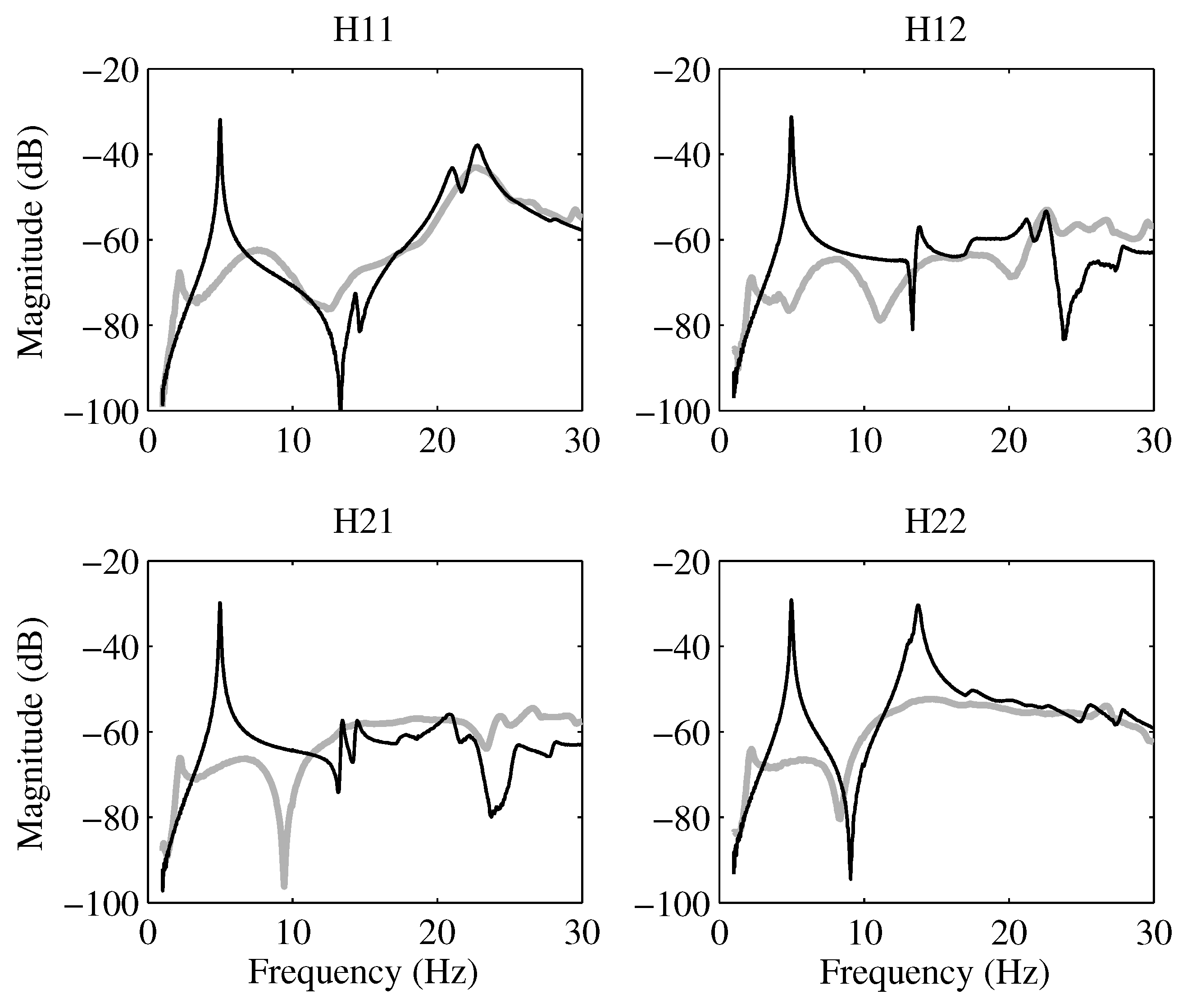
3.4. Robust Analysis: Simulation Results

Firstly, note that the stability condition of the controller optimization is that all the eigenvalues of the state matrix of Figure 1 must be positive. The real part of the closest pole to the imaginary axis is −1.63, which indicates that the system is stable. Secondly, the natural frequencies of the structure were considered variables with an error of ±25%. Figure 8 shows the plot of the identified model (blue) and the system with a variation of +25% (yellow) and of −25% (red).
Secondly, the controller was simulated with the three systems. Figure 9 shows the simulation results, where the closed-loop simulation with the identified model is plotted in blue and the system with a variation of +25% and of −25% in yellow and red, respectively. In addition, the real parts of the closest pole to the imaginary axis are −0.1007 (+25%) and 0.0995 (−25%). Note that the peak at 1.72 Hz in the yellow plot corresponds to the shaker. This indicates a possible problem of stability if the natural frequency of the system is considered less than −25%. Note that the actuator bandwidth (i.e., frequency response) significantly affects the stability of the overall control scheme and limits the maximum damping imparted to the structure. Thus, the IRC parameters not only minimize the peak FRFs but also maintain the stability of the controlled system for the considered variation of +25%.

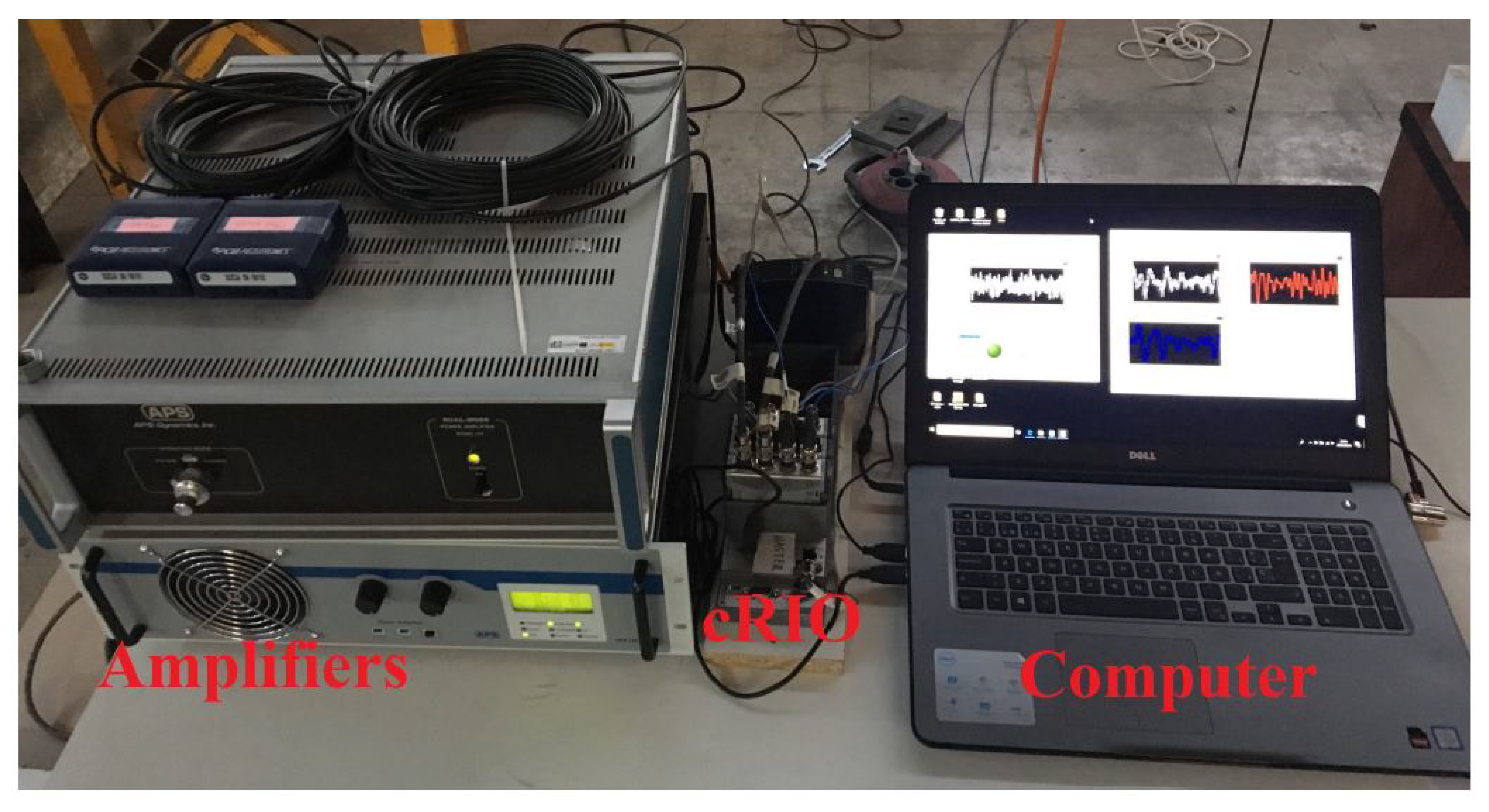
4. Experimental Results

The controls were carried out using the LabVIEW Real-Time Module, National Instrument, Austin, TX, USA and the NI acquisition system cRIO-9066, National Instrument, Austin, TX, USA equipped with the analog output card NI-9203 and the IEPE conditioning cards NI-9234 to measure the structure response. It is important to highlight that saturation blocks are included to reduce stroke and force saturation risks. In Figure 10, the cRIO, amplifiers, and a computer recording the results coming from the second loop of the block diagram can be seen.
Before defining the perturbation in the experimental results, the actuator stroke saturation, which also limits the maximum damping imparted, must be considered. Note that this stroke saturation could result in dramatic adverse effects on the actuator performance and its hardware. This issue is important to define the maximum perturbation the controller can damp in its linear behavior.
Only two APS Electro-Seis Dynamic Shaker 400 are available in the laboratory, which are driven by the power amplifiers APS 144 and 145. Thus, to compare the FRFs obtained in open loop (Figure 7) with the closed-loop results, an additional excitation must be added. This excitation was an impulse hammer (PCB PIEZOTRONICS model 086D50). Figure 11 shows the locations of the two actuators at nodes 16 and 22. Near these nodes (actuators and accelerometers), three impacts to the floor, with an interval of 20 s, were carried out in each node.
Figure 12 shows the comparison between the OL and CL results. Notably, the damping of the first mode exceeded 30 dB at nodes 16 and 22, with node 22 exhibiting a damping of over 20 dB. Additionally, a minor peak around 2.2 Hz is evident in the closed-loop responses. This peak was attributed to the characteristics of the inertial actuator utilized. Its presence governs instability at lower frequencies, where the poles of the actuator may become unstable if the values of γ 1 and γ 2 are significantly increased.
The results depicted in Figure 12 underscore the effectiveness of the devised MIMO IRC scheme in efficiently damping multiple unmodeled structural modes while maintaining stability. Importantly, the stability conditions established in this study ensure that any MIMO controller adhering to these criteria is inherently robust against spillover issues, thereby making it suitable for practical implementation across various engineering applications.
It is noteworthy that the methodology employed in this research can serve as a blueprint for designing stability-based AVC schemes capable of addressing similar low-frequency challenges encountered in different control contexts. By leveraging alternative control laws, which may have been previously hindered by comparable low-frequency limitations, engineers can now employ a similar approach to develop robust and effective AVC strategies tailored to their specific system requirements.

5. Conclusions

This works extends the utilization of SISO IRC, originally introduced in [34], to a MIMO IRC configuration. This extension has considered the general framework outlined in [35] and the MIMO IRC proposed in [36]. The resulting MIMO IRC keeps the main advantages of the IRC proposed in [34], but in a MIMO configuration. The main advantages are as follows:
  • The controller’s resilience against spillover effects, which has been tested in experiments by impact perturbation, which excites higher vibration modes.
  • The robustness to system variations, which has been illustrated in the simulation results.
With respect to the stability, the section “Robust Analysis: Simulation Results” also shows that the stability depends on the ration between the first vibration mode and the natural frequency of the actuator. The same conclusion, for SISO IRC, was shown in [34], but here, it has been extended to the MIMO case. Thus, if the natural frequency decreases with respect to the model considered for the controller designed, the closed-loop system might be degraded. Future work will focus on deducing the stability conditions for the novel IRC scheme, incorporating elements such as the Negative Imaginary Frequency Response property and the Small-Gain theorem [45].
Finally, this work has a big practical application to the active vibration control of civil structures, where non-resonant structural responses and resonant vibrations must be attenuated [23].

Author Contributions

Conceptualization, E.P., S.S.A., E.P. and I.M.D.; software, I.M.D. and X.W.; validation, X.W., I.M.D. and E.P.; formal analysis, E.P. and S.S.A.; investigation, E.P., I.M.D. and S.S.A.; resources, E.P., I.M.D. and S.S.A.; data curation, E.P. and X.W.; writing—review and editing, I.M.D. and S.S.A.; visualization, X.W.; supervision, E.P.; project administration, I.M.D.; funding acquisition, E.P. and I.M.D. All authors have read and agreed to the published version of the manuscript.

Funding

This research was funded by PID2022-140117NB-I00 (Spanish Government) and the National Natural Science Foundation of China (No. 52308220).

Data Availability Statement

The original contributions presented in the study are included in the article, further inquiries can be directed to the corresponding author.

Conflicts of Interest

The authors declare no conflicts of interest.

References

  1. Ebrahimpour, A.; Sack, R.L. A review of vibration serviceability criteria for floor structures. Comput. Struct. 2005, 83, 2488–2494. [Google Scholar] [CrossRef]
  2. Fanning, P.J.; Healy, P.; Pavic, A. Pedestrian Bridge Vibration Serviceability: A Case Study in Testing and Simulation. Adv. Struct. Eng. 2010, 13, 861–873. [Google Scholar] [CrossRef]
  3. Bouzari, N.; Van Engelen, N.; Cheng, S. Evaluation of Pedestrian-Induced In-Service Building Floor Performance Based on Short-Term Monitoring. J. Perform. Constr. Facil. 2023, 37, 04023045. [Google Scholar] [CrossRef]
  4. Wang, Z.; Song, L.; Cheng, Z.; Yang, H.; Wen, J.; Qi, M. Finite Element Model for Vibration Serviceability Evaluation of a Suspended Floor with and without Tuned Mass Dampers. Buildings 2023, 13, 309. [Google Scholar] [CrossRef]
  5. Avci, O.; Catbas, F.N. Editorial: Human-Induced Excitations and Vibrations Serviceability of Civil Engineering Structures. Front. Built Environ. 2022, 8, 846351. [Google Scholar] [CrossRef]
  6. Fujino, Y.; Siringoringo, D. Vibration Mechanisms and Controls of Long-Span Bridges: A Review. Struct. Eng. Int. 2013, 23, 248–268. [Google Scholar] [CrossRef]
  7. Chen, J.; Han, Z.; Xu, R. Effects of human-induced load models on tuned mass damper in reducing floor vibration. Adv. Struct. Eng. 2019, 22, 2449–2463. [Google Scholar] [CrossRef]
  8. Shi, W.; Wang, L.; Lu, Z.; Zhang, Q. Application of an Artificial Fish Swarm Algorithm in an Optimum Tuned Mass Damper Design for a Pedestrian Bridge. Appl. Sci. 2018, 8, 175. [Google Scholar] [CrossRef]
  9. Caetano, E.; Cunha, A.; Magalhães, F.; Moutinho, C. Studies for controlling human-induced vibration of the Pedro e Inês footbridge, Portugal. Part 1: Assessment of dynamic behaviour. Eng. Struct. 2010, 32, 1069–1081. [Google Scholar] [CrossRef]
  10. Wang, C.; Shi, W. Optimal Design and Application of a Multiple Tuned Mass Damper System for an In-Service Footbridge. Sustainability 2019, 11, 2801. [Google Scholar] [CrossRef]
  11. Xie, Z.; Zhang, Y. Dynamic Response Measurement and Finite Element Analysis of Large-Span Pedestrian Corridor. Buildings 2023, 13, 2857. [Google Scholar] [CrossRef]
  12. Li, J.; Liu, X. Human-Induced Vibration Analysis and Reduction Design for Super Long Span Pedestrian Arch Bridges with Tuned Mass Dampers. Appl. Sci. 2023, 13, 8263. [Google Scholar] [CrossRef]
  13. Wen, Q.; Hua, X.G.; Chen, Z.Q.; Yang, Y.; Niu, H.W. Control of Human-Induced Vibrations of a Curved Cable-Stayed Bridge: Design, Implementation, and Field Validation. J. Bridge Eng. 2016, 21, 04016028. [Google Scholar] [CrossRef]
  14. Zhou, L.; Wan, S. Vibration Control of Footbridges Based on Local Resonance Band Gaps. J. Struct. Eng. 2022, 148, 04022137. [Google Scholar] [CrossRef]
  15. Liu, K.; Shi, Q.; Liu, Y.; Liu, L.; Zhou, F. Investigation of an improved tuned liquid column gas damper for the vertical vibration control. Mech. Syst. Signal Process. 2023, 196, 110340. [Google Scholar] [CrossRef]
  16. Wang, L.; Nagarajaiah, S.; Shi, W.; Zhou, Y. Semi-active control of walking-induced vibrations in bridges using adaptive tuned mass damper considering human-structure-interaction. Eng. Struct. 2021, 244, 112743. [Google Scholar] [CrossRef]
  17. Shi, W.; Wang, L.; Lu, Z.; Gao, H. Study on Adaptive-Passive and Semi-Active Eddy Current Tuned Mass Damper with Variable Damping. Sustainability 2018, 10, 99. [Google Scholar] [CrossRef]
  18. Wang, L.; Nagarajaiah, S.; Zhou, Y.; Shi, W. Experimental study on adaptive-passive tuned mass damper with variable stiffness for vertical human-induced vibration control. Eng. Struct. 2023, 280, 115714. [Google Scholar] [CrossRef]
  19. Hudson, M.; Reynolds, P. Implementation considerations for active vibration control in the design of floor structures. Eng. Struct. 2012, 44, 334–358. [Google Scholar] [CrossRef]
  20. Wani, Z.R.; Tantray, M.; Noroozinejad Farsangi, E.; Nikitas, N.; Noori, M.; Samali, B.; Yang, T. A Critical Review on Control Strategies for Structural Vibration Control. Annu. Rev. Control. 2022, 54, 103–124. [Google Scholar] [CrossRef]
  21. Terrill, R.; Bäumer, R.; Van Nimmen, K.; Van den Broeck, P.; Starossek, U. Twin Rotor Damper for Human-Induced Vibrations of Footbridges. J. Struct. Eng. 2020, 146, 04020119. [Google Scholar] [CrossRef]
  22. Liu, X.; Schauer, T.; Goldack, A.; Schlaich, M. Multi-Modal Active Vibration Control of a Lightweight Stress-Ribbon Footbridge Based on Subspace Identification. IFAC-PapersOnLine 2017, 50, 7058–7063. [Google Scholar] [CrossRef]
  23. Wang, L.; Zhou, Y.; Shi, W. Dynamic test, monitoring and active control of non-resonant running-induced vibration for floor structure. Structures 2024, 63, 106348. [Google Scholar] [CrossRef]
  24. Alujević, N.; Zhao, G.; Depraetere, B.; Sas, P.; Pluymers, B.; Desmet, W. Optimal vibration control using inertial actuators and a comparison with tuned mass dampers. J. Sound Vib. 2014, 333, 4073–4083. [Google Scholar] [CrossRef]
  25. Chesné, S.; Milhomem, A.; Collette, C. Enhanced Damping of Flexible Structures Using Force Feedback. J. Guid. Control. Dyn. 2016, 39, 1654–1658. [Google Scholar] [CrossRef]
  26. Ramírez-Senent, J.; Gallegos-Calderón, C.; García-Palacios, J.H.; Díaz, I.M. Active control of human-induced vibrations on lightweight structures via electrodynamic actuator dynamics inversion. J. Vib. Control. 2024, 30, 88–103. [Google Scholar] [CrossRef]
  27. Xue, K.; Igarashi, A.; Kachi, T. Independent modal space phase-lead velocity feedback control of floor vibration. Struct. Control. Health Monit. 2022, 29, e2954. [Google Scholar] [CrossRef]
  28. Ahmadi, M.W. Preventing stroke saturation of inertial actuators used for active vibration control of floor structures. Struct. Control. Health Monit. 2020, 27, e2546. [Google Scholar] [CrossRef]
  29. Hanagan, L.M.; Kulasekere, E.C.; Walgama, K.S.; Premaratne, K. Optimal Placement of Actuators and Sensors for Floor Vibration Control. J. Struct. Eng. 2000, 126, 1380–1387. [Google Scholar] [CrossRef]
  30. Pereira, E.; Díaz, I.M.; Hudson, E.J.; Reynolds, P. Optimal control-based methodology for active vibration control of pedestrian structures. Eng. Struct. 2014, 80, 153–162. [Google Scholar] [CrossRef]
  31. Nyawako, D.S.; Reynolds, P. Comparative studies of global and targeted control of walkway bridge resonant frequencies. J. Vib. Control. 2016, 24, 1670–1686. [Google Scholar] [CrossRef]
  32. Camacho-Gómez, C.; Wang, X.; Pereira, E.; Díaz, I.; Salcedo-Sanz, S. Active vibration control design using the Coral Reefs Optimization with Substrate Layer algorithm. Eng. Struct. 2018, 157, 14–26. [Google Scholar] [CrossRef]
  33. Zamani, A.A.; Etedali, S. Optimal fractional-order PID control design for time-delayed multi-input multi-output seismic-excited structural system. J. Vib. Control. 2021, 29, 802–819. [Google Scholar] [CrossRef]
  34. Díaz, I.M.; Pereira, E.; Reynolds, P. Integral resonant control scheme for cancelling human-induced vibrations in light-weight pedestrian structures. Struct. Control. Health Monit. 2010, 19, 55–69. [Google Scholar] [CrossRef]
  35. Wang, X.; Pereira, E.; García-Palacios, J.H.; Díaz, I.M. A general vibration control methodology for human-induced vibrations. Struct. Control. Health Monit. 2019, 26, e2406. [Google Scholar] [CrossRef]
  36. Bhikkaji, B.; Moheimani, S.O.R.; Petersen, I.R. A Negative Imaginary Approach to Modeling and Control of a Collocated Structure. IEEE/ASME Trans. Mechatronics 2012, 17, 717–727. [Google Scholar] [CrossRef]
  37. Gawronski, W.K. Advanced Structural Dynamics and Active Control of Structures; Springer: New York, NY, USA, 2004. [Google Scholar] [CrossRef]
  38. Preumont, A. Vibration Control of Active Structures; Springer International Publishing: Berlin/Heidelberg, Germany, 2018. [Google Scholar] [CrossRef]
  39. Aphale, S.S.; Fleming, A.J.; Moheimani, S.O.R. Integral resonant control of collocated smart structures. Smart Mater. Struct. 2007, 16, 439–446. [Google Scholar] [CrossRef]
  40. Kandil, A.; Hamed, Y.S. Integral Resonant Controller for Suppressing Car’s Oscillations and Eliminating its Inherent Jump Phenomenon. Eur. J. Pure Appl. Math. 2023, 16, 2729–2750. [Google Scholar] [CrossRef]
  41. Loṕez-Romero, M.; Santos Peñas, M. A Positive Position Feedback controller for vibration control of wind turbines. Energy Rep. 2023, 9, 1342–1353. [Google Scholar] [CrossRef]
  42. Multiphysics, A. Release 2022 R2, Help System; ANSYS Inc.: Canonsburg, PA, USA, 2022. [Google Scholar]
  43. McKelvey, T.; Akcay, H.; Ljung, L. Subspace-based multivariable system identification from frequency response data. IEEE Trans. Autom. Control. 1996, 41, 960–979. [Google Scholar] [CrossRef]
  44. ISO2631-1:1997; Mechanical Vibration and Shock. Evaluation of Human Exposure to Whole-Body Vibration Part 1: General Requirements. International Organization for Standardization: Geneva, Switzerland, 1997.
  45. Patra, S.; Lanzon, A. Stability Analysis of Interconnected Systems With “Mixed” Negative-Imaginary and Small-Gain Properties. IEEE Trans. Autom. Control. 2011, 56, 1395–1400. [Google Scholar] [CrossRef]
Figure 1. Block diagram of the proposed MIMO IRC scheme.
Applsci 14 06784 g001
Figure 2. Photograph of the laboratory-based floor structure employed in this work for open-loop characterization, model development, and closed-loop experimental validation of the proposed control scheme.
Applsci 14 06784 g002
Figure 3. Node numbers and coordinates initialized on the laboratory-based floor structure shown in Figure 2.
Applsci 14 06784 g003
Figure 4. ANSYS results showing the first three resonant modes of the floor structure.
Applsci 14 06784 g004
Figure 5. (a) Inertial actuator: electrodynamic shaker (APS Electro-Seis Dynamic Shaker 400). (b) Lumped mass model for the actuator.
Applsci 14 06784 g005
Figure 6. Inertial mass actuator working in voltage mode.
Applsci 14 06784 g006
Figure 7. Magnitude (in dB) plot of the identified model (black) with the measured FRF (grey), demonstrating excellent alignment between the actual system and its developed model.
Applsci 14 06784 g007
Figure 8. Magnitude (in dB) plot of the identified model (blue) and the system with a variation of +25% (yellow) and of −25% (red).
Applsci 14 06784 g008
Figure 9. Magnitude (in dB) plot of the closed-loop simulation with the identified model (blue) and the system with a variation of +25% (yellow) and of −25% (red).
Applsci 14 06784 g009
Figure 10. Experimental setups.
Applsci 14 06784 g010
Figure 11. IRC MIMO control of the laboratory floor structure.
Applsci 14 06784 g011
Figure 12. Magnitude (in dB) plot of the open-loop (black) and closed-loop (grey) FRFs of the laboratory-based floor structure, clearly depicting the efficacy of the proposed control scheme in imparting multimode damping.
Applsci 14 06784 g012
Disclaimer/Publisher’s Note: The statements, opinions and data contained in all publications are solely those of the individual author(s) and contributor(s) and not of MDPI and/or the editor(s). MDPI and/or the editor(s) disclaim responsibility for any injury to people or property resulting from any ideas, methods, instructions or products referred to in the content.

