Article

Dynamic Simulation Model and Performance Optimization of a Pressurized Pulsed Water Jet Device

by
Yuanfei Ling
1,2,*,
Xiaoqiang Wang
1,2 and
Jiren Tang
3
1
School of Mechatronics Engineering, Henan University of Science and Technology, Luoyang 471003, China
2
Collaborative Innovation Center of Hennan Province for High-End Bearing, Henan University of Science and Technology, Luoyang 471000, China
3
State Key Laboratory of Coal Mine Disaster Dynamics and Control, Chongqing University, Chongqing 400030, China
*
Author to whom correspondence should be addressed.
Appl. Sci. 2024, 14(15), 6788; https://doi.org/10.3390/app14156788 (registering DOI)
Submission received: 29 June 2024 / Revised: 23 July 2024 / Accepted: 31 July 2024 / Published: 3 August 2024

Abstract

:
Pulsed water jet technology has broad application prospects in the field of rock breaking. The pressurized pulsed water jet (PPWJ) is a new type of pulsed jet that offers high-amplitude pressurization, variable pulse pressure and frequency, and a high energy usage rate. To achieve a more destructive and powerful pulsed water jet, a dynamic simulation model of the device was established by using the AMESim software (v1400) based on the operational principle of PPWJs, and the simulation model was validated against the experimental results. The relationships between the key structural parameters of the PPWJ device and the pulse parameters were quantitatively investigated. The pulse pressure and frequency can be increased by appropriately increasing the nozzle diameter or boost ratio, and the pulse pressure will drop if the nozzle diameter or boost ratio exceeds a threshold value. Increasing the maximum displacement or action area of the piston will increase pulse length while decreasing pulse frequency; a proper match of the maximum displacement or action area of the piston will assure pulse peak pressure. The maximum outer diameter of the piston only affects the pulse frequency. The key structural parameters of the device were optimized on that foundation. Compared to the original device, the optimized device resulted in an increase in pulse frequency and jet output energy, leading to larger diameter and volume of erosion pits at the same stand-off distance and erosion time. The findings of this study offer valuable scientific insights for achieving efficient rock breaking with PPWJ.

1. Introduction

High-pressure water jet technology is a new technology which has developed rapidly in recent decades [1,2,3] and which has been used in various fields such as mining, oil and gas extraction, and tunneling [4,5,6,7]. The utilization of a high-pressure water jet for rock breaking is favored as a promising technology due to its heat-free, dust-free, and highly effective nature [8,9,10]. Currently, a variety of types of water jets have been developed for rock breaking, including cavitation water jets, abrasive water jets, rotating water jets, pulsed water jets, and more. Among them, the pulsed water jet (PWJ) with a discrete water column in the form of a pulse can cause serious damage to the surface and internal structure of the target by producing short-term, transiently high pressure and periodic impact forces. Considerable evidence indicates that PWJ can result in significantly more damage to the target compared to a continuous water jet (CWJ) at the same energy level [11,12,13].
For better application in engineering, different types of PWJ have been created to fulfill diverse application needs. One type is the self-excited oscillation pulsed water jet (SOPWJ). Due to the special nozzle structure, it can convert a continuous jet into a pulsed jet without requiring external excitation conditions. To enhance the efficiency of a SOPWJ for rock breaking, various research studies have concentrated on erosion performance, the characteristics of the flow field, and the oscillation mechanism. Li et al. [14,15,16] studied the effect of nozzle inner surface roughness, inlet area discontinuity, and feed pipe diameter on the erosion performance of the SOPWJ jet. Zhou et al. [17] and Zhang et al. [18] investigated the velocity and pressure characteristics of a SOPWJ through modifications in the structural parameters of the nozzle and the operational parameters of the system, respectively. Liu et al. [19,20,21] introduced the gas-spring theory to elucidate the oscillation mechanism of SOPWJ, and it was found that the oscillating frequency is predominantly controlled by the cavitation clouds in the chamber. Kolsek et al. [22] studied the asymmetric flow and sustained oscillation phenomena of fluid in a symmetric cavity under high-Reynolds-number and high-cavity-diameter-ratio conditions through numerical simulation. Monika et al. [23] highlighted the importance of tool geometry and changes in water pressure at the inlet to the self-excited pulsating heads and the dynamics of the PWJ. Nevertheless, the pulse parameters and operational performance of a SOPWJ are challenging to regulate owing to its high sensitivity to supply pressure and nozzle structure. Furthermore, the pulse pressure typically falls short of 40 MPa, rendering it inadequate for breaking hard rocks. Another type of PWJ is the ultrasonically modulated pulsed water jet (UMPWJ) that utilizes ultrasonic waves to create pulses with high frequency, which was first proposed by Vijay [24]. On this foundation, Foldyna et al. [25] found that the cutting depth of the UMPWJ was significantly greater than that of the CWJ, and the grooves formed were more regular. Zelenak et al. [26] applied the shadowgraph technique and particle tracking velocimetry processing algorithms to visualize the UMPWJ structures and velocity vector fields. Tripathi et al. [27] and Říha et al. [28] demonstrated that the erosion performance of UMPWJ surpasses that of a CWJ operating at the same parameters. Raj et al. [29] and Tripathi et al. [30] conducted a cutting experiment on sandstone with a UMPWJ. The results of the experiment indicated that the pulse frequency has a significant effect on the depth, width, and volume of the groove. Srivastava et al. [31] and Hloch et al. [32] conducted additional research on UMPWJs, exploring erosion performance based on micro-morphology and varying operating parameters. Due to the high-frequency characteristics of ultrasonic waves, the study concentrated on UMPWJ with a pulse frequency exceeding 20 kHz, while PWJs with a lower pulse frequency were not considered. Many scholars highlighted the distinct benefits of utilizing a PWJ with a low pulse frequency for rock breaking. Jiang et al. [33] conducted a simulation of the rock breaking process using a PWJ and observed that a water-cushion effect would emerge and reduce the rock breaking efficiency under a high pulse frequency. Polyakov et al. [34] demonstrated that the PWJ has a high cutting capacity with a low range of pulse frequencies by conducting the rock cutting test under different hydraulic parameters. An interrupted pulsed water jet (IPWJ) has been proposed and widely studied in order to achieve the threshold pressure required for rock breaking and to cater to the demands of low-pulse-frequency applications.
The IPWJ employs a slotted disk to periodically divide the continuous water jet into distinct water slugs. This method is widely regarded as the most convenient for generating intermittent water jets with easily controllable pulse parameters for practical applications [35]. Dehkhoda et al. [36,37] found that the pulse frequency and the pulse duration affected the formation and development of the failure zone, respectively, and the pulse frequency and pulse duration jointly promoted internal damaging of the rock. To reveal the mechanical mechanism of rock breaking by IPWJs, Xue et al. [12] simulated the propagation of stress waves in the rock through the method of smooth particle hydrodynamics. Lu et al. [38,39] obtained the flow field structure of an IPWJ by numerical simulation and testing of morphology capture. They revealed that the flow field structure of an IPWJ was associated with impact performance. Wang et al. [40] studied the effect of disc-to-nozzle distance and disc-to-target distance on rock breaking, aiming to improve the efficiency of IPWJs for rock breaking.
Compared with SOPWJs and UMPWJs, IPWJs have a unique advantage for rock breaking, but the pulse pressure depends on the pump pressure. To enhance the potency and destructive capability of the PWJ for rock breaking, the rated pump pressure needs to be further increased due to the high compression strength of rocks [41]. However, the cost of increasing rated pump pressure is much higher than that of equipment manufacturing and maintenance, thereby constraining the development and utilization of PWJs. For better application of PWJs for rock breaking, a pressurized pulsed water jet (PPWJ) device was developed by Ling et al. [42] and proved that the rock breaking capability of a PPWJ surpasses that of a CWJ. A PPWJ with higher pulse pressure at lower input pressure can be created without requiring ultra-high-pressure equipment. To improve the performance of the device, a dynamic simulation model was established to obtain its dynamic characteristics and predict the variation curves of jet pressure. Meanwhile, the effect of key structural parameters of the device on the pulse parameters was analyzed, and the device was optimized to further increase rock breaking efficiency on that foundation.

2. Formation Principle of PPWJ

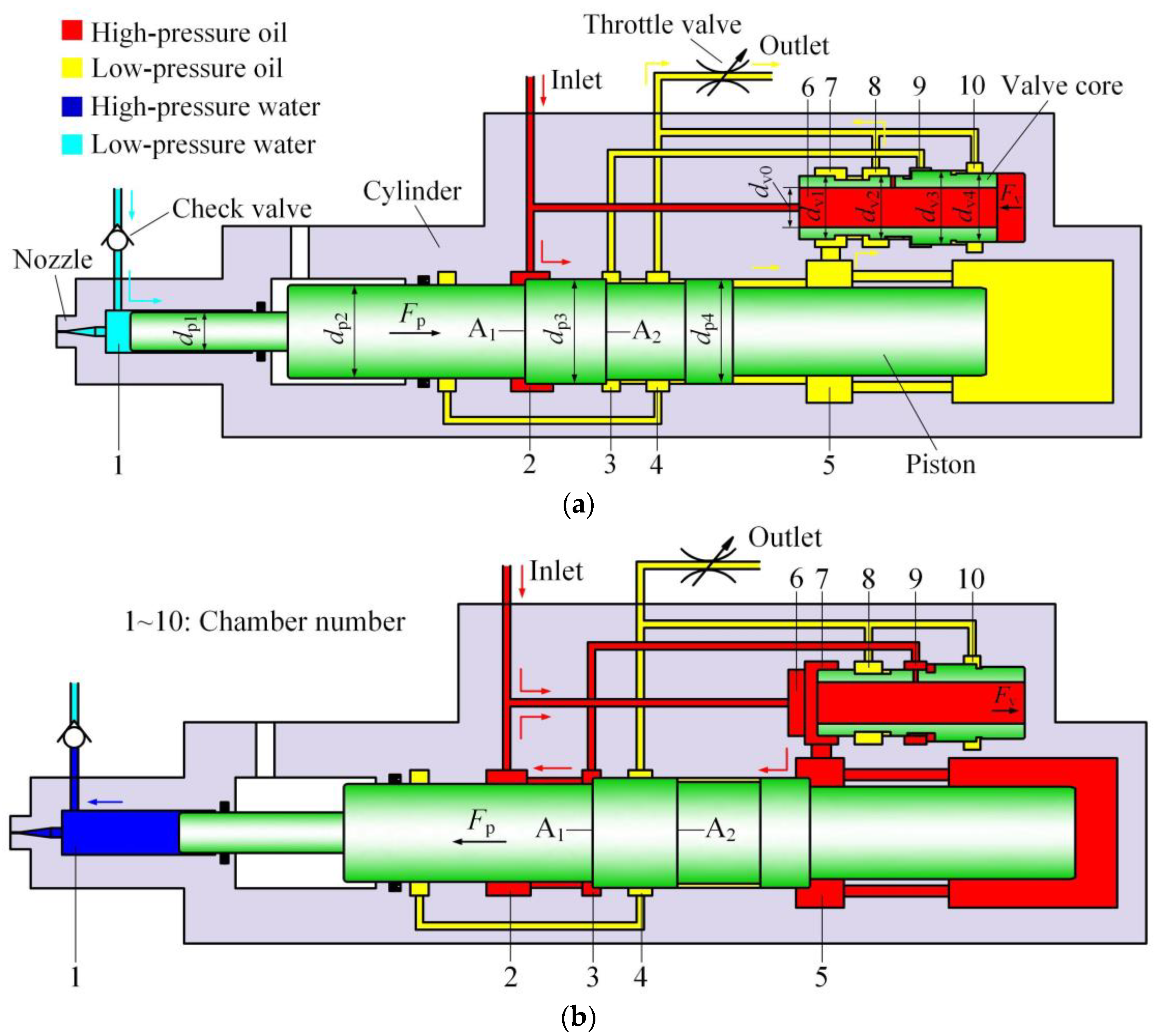
2.1. Structure of the PPWJ Device

The PPWJ device consists primarily of a nozzle, cylinder, piston, and valve core, and utilizes hydraulic oil as its operating fluid [42]. The connected relation between the flow channel and chamber inside the device is shown in Figure 1. The valve core alters the hydraulic oil flow direction to drive the piston back and forth in the cylinder, and the piston’s motion status influences the positioning switch of the valve core. The piston is a substantial stepped rod, and the diameter of each segment meets the following criteria: dp3 = dp4 > dp2 > dp1. The valve core is a hollow stepped rod, and the diameter of each segment also conforms to the following criteria: dv3 > dv4 > dv2 = dv1.

2.2. Operational Principle of the PPWJ Device

One operational cycle of the device involves the forward and backward motion states of the piston, as shown in Figure 1a,b, respectively. When surface A2 of the piston moves to chamber 3, chambers 9 and 4 are connected, allowing chamber 9 to be linked to the oil outlet. The hydraulic force Fv acting on the valve core fulfills Equation (1) as follows:
F v = π 4 ( d v 1 2 d v 0 2 ) p 2 π 4 ( d v 4 2 d v 0 2 ) p 2 < 0
where p2 is the inlet pressure. At this point, the valve core shifts to the left, causing the piston to begin its backward stroke due to the hydraulic thrust Fp. The low-pressure oil in chamber 5 then flows sequentially through chamber 7 and chamber 8 before reaching the oil outlet. Meanwhile, the low-pressure water enters chamber 1 through the check valve.
When surface A1 of the piston moves to chamber 3, chambers 9 and 2 are connected, allowing chamber 9 to be connected to the oil inlet. The hydraulic force Fv acting on the valve core fulfills Equation (2) as follows:
F v = π 4 ( d v 1 2 d v 0 2 ) p 2 + π 4 ( d v 3 2 d v 2 2 ) p 2 π 4 ( d v 4 2 d v 0 2 ) p 2 > 0
At this point, the valve core shifts to the right, and the piston starts to stroke under the action of hydraulic thrust Fp. As the piston moves, the pressure in chamber 1 increases, causing the check valve to shut. The pressurized water generates kinetic energy as it passes through the nozzle, and is subsequently ejected at high velocities. During the stroke stage of the piston, the high-pressure oil in chamber 2 sequentially flows through chamber 6 and chamber 7 to reach chamber 5, forming a differential connection.
Under continuous hydraulic oil, the position of the valve core is shifted to alter the flow direction of the hydraulic oil that drives the piston to move back and forth, intermittently expelling the water in chamber 1, leading to periodic changes in the pressure of chamber 1. Furthermore, the jet pressure exceeds the inlet pressure as a result of the disparate piston action areas in the oil chamber and water chamber. Therefore, under the continuous injection of low-pressure oil, consecutive high-pressure pulse jets can be generated without extra power and high-pressure equipment, with low cost and a simple operation.

2.3. Analysis of the Pulse Parameters of a PPWJ

The pulse parameters of PWJ encompass pulse pressure, pulse frequency, and pulse duration. These factors play a pivotal role in determining the rock breaking capability of PWJ. The determination of the pulse parameters of PPWJ is based on the water jet theory and the operational principle of the device. The formation of a high-pressure PWJ is achieved during the piston stroke stage, and its modeling method is based on the principles of Lumped Element Modeling [43].
When the water in chamber 1 is squeezed by the piston, there is an estimated linear correlation between the pressure and density of the water [44]:
p w = K w ( ρ w ρ w 0 1 )
where pw is the pressure of chamber 1 during pressurization process; Kw is the bulk modulus of water; ρw is the density of water; ρw0 is the original density of water; and ρw = ρw0 when pw = 0.
As a derivation of Equation (3) with respect to time, we have the following:
d ρ w d t = ρ w 0 K w   d p w d t
Based on the Reynolds transport theorem [45], the equation of continuity or conservation of fluid mass can be derived:
d m w d t = ( t ρ w d V ) C V + ( ρ w v w n d A ) C S = 0
where mw and vw are the mass and velocity of water, respectively; n is the outward normal to the control surface; V represents the volume inside the control volume domain; and A represents the boundary surface.
The first term of Equation (5) indicates the rate at which the accumulated mass inside chamber 1 changes for compressible water:
( t ρ w d V ) C V = t ( ρ w A ( l x sp ) ) = π 4 d p 1 2 ( d ρ w d t ( l x sp ) v sp ρ w )
where A is the cross sectional area of chamber 1; l is the length of chamber 1; and xsp and vsp are, respectively, the stroke displacement and stroke velocity of the piston.
The second term of Equation (5) implies the rate of flow mass outflow through the nozzle:
( ρ w v w n d A ) C S = ρ w v w a = π 4 d n 2 ρ w v w
where a is the cross sectional area of the nozzle and dn is the nozzle diameter.
In combination with Equations (5)–(7), we have the following:
d p 1 2 ( d ρ w d t ( l x sp ) v sp ρ w ) + d n 2 ρ w v w = 0
The Bernoulli hydrodynamic equation is utilized to estimate the mean velocity of the jet as it exits the nozzle based on value of the pressure inside chamber 1:
u w = c d 2 p w ρ w
where cd is the discharge coefficient of the nozzle.
During the stroke stage of the piston, chamber 2 and chamber 5 are both connected to the oil inlet, allowing hydraulic oil to flow into chamber 5 and drive the piston to the left; the oil volume compression rate can be expressed as follows:
d V s d t = q sin + π 4 ( d p 3 2 d p 2 2 ) v sp π 4 d p 4 2 v sp = q sin π 4 d p 2 2 v sp
where Vs is the high-pressure oil volume in the stroke stage of the piston and qsin is the effective input flow rate of chamber 5 in the stroke stage of the piston.
Placing Equations (3), (4), (9), and (10) in Equation (8) provides the jet pressure as follows:
d p w d t = ρ w 0 d p 1 2 ( p w + K w ) ( q sin d V s d t ) π 4 c d d n 2 d p 2 2 2 ρ w 0 K w p w ( p w + K w ) π 4 d p 1 2 d p 2 2 ( l x sp ( t ) )
During the backward stroke stage of the piston, chamber 5 is connected to the oil outlet, allowing hydraulic oil to flow into chamber 2 and drive the piston to the right; the oil volume compression rate can be expressed as follows:
d V r d t = q rin π 4 ( d p 3 2 d p 2 2 ) v rp
where Vr is the high-pressure oil volume in the backward stroke stage of the piston; qrin is the effective input flow rate of chamber 2 in the backward stroke stage of the piston; and vrp is the backward stroke velocity of the piston.
The maximum displacement of the piston is provided by the following:
h p = 0 t r v rp dt = 0 t s v sp dt
where hp is the maximum displacement of the piston; tr is the backward stroke duration of the piston; and ts is the stroke duration of the piston as well as the pulse duration.
The pulse frequency is provided by the following:
f = 1 t r + t s
where f is the pulse frequency.

3. Simulation of Dynamic Characteristics of the PPWJ Device

Through theoretical analysis, it was found that the pulse parameters are affected by the motion state of the piston. In the actual operational process of the device, the velocity of the piston changes periodically under high frequency, which directly leads to the drastic change in the pressure and flow rate of the system. The movement law of the piston cannot be accurately described by a linear mathematical model. Therefore, it is difficult to accurately predict the pulse parameters, which affects the structural optimization and performance improvement of the device. Also, the device is composed of complex and precise parts that are difficult to machine. The acquisition of the change law of the pulse parameters through a large number of experiments is time-consuming and labor-intensive. AMESim (v1400) is dynamic analysis software for hydraulic/mechanical systems, which uses standard ISO icons and intuitive multi-port block diagrams to realize system modeling and simulation. In this study, the AMESim software is utilized to simulate the operation of the device.

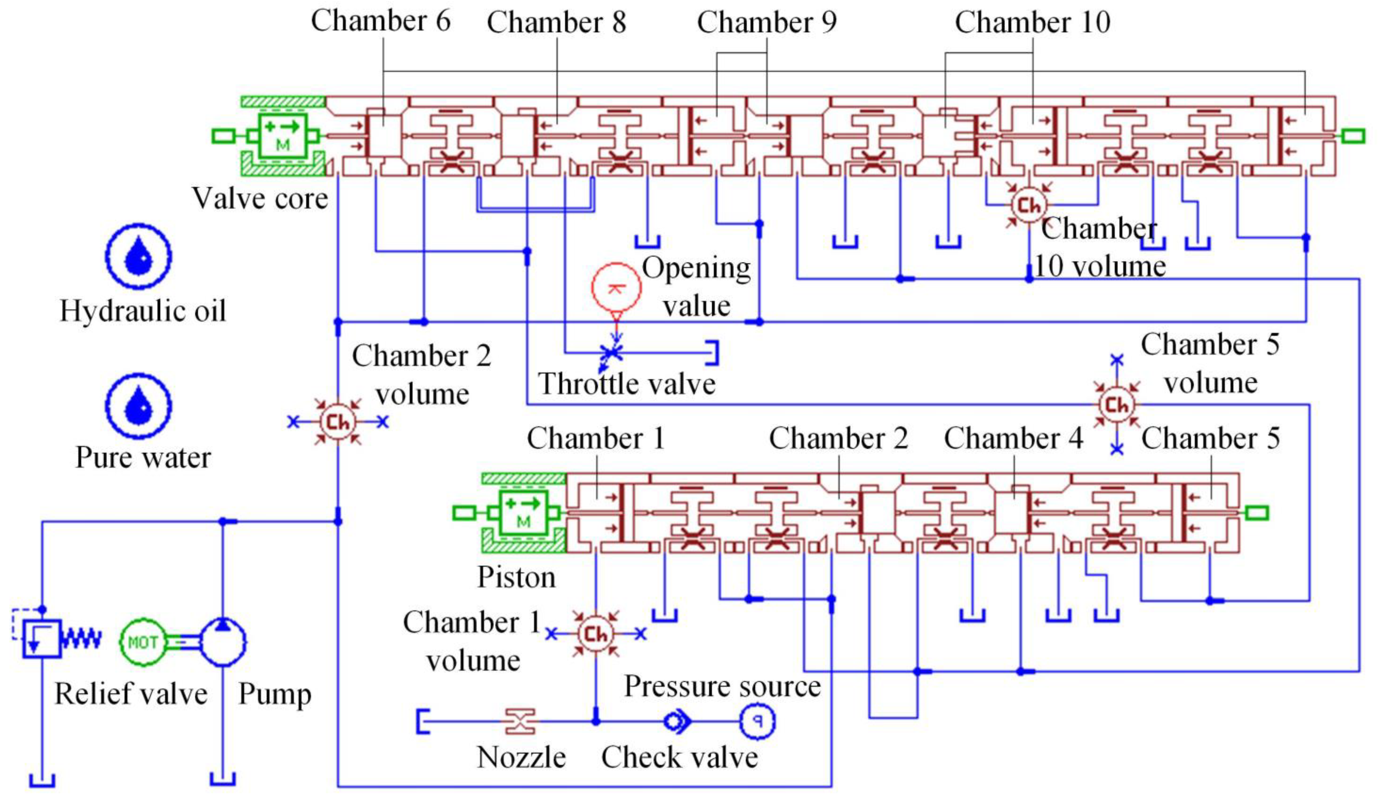
3.1. Simulation Model

Based on the operational principle and structure of the device, suitable sub-models are selected from the model library of the AMESim software to build a simulation model of the system. As shown in Figure 2, the main elements of the system are the hydraulic pump, PPWJ device, check valve, relief valve, and throttle valve. The relief valve is used to control the pulse pressure by regulating qsin, and the throttle valve is used to control the pulse frequency by regulating qrin. The simulation setup time is 2 s with a step size of 0.01 s.

3.2. Governing Equations

The construction of a PPWJ is complex, and the performance of the jet is affected by many factors. To reduce the calculation time of the model, some assumptions are provided as follows: the temperature and bulk modulus of the fluid are constant; the mechanical friction loss and oil pressure loss are ignored; the water inside the chamber is incompressible; all components are regarded as absolute rigid bodies except for the hydraulic oil delivery pipeline; and the fluid dynamic phenomenon related to the flows through the pipes are ignored.

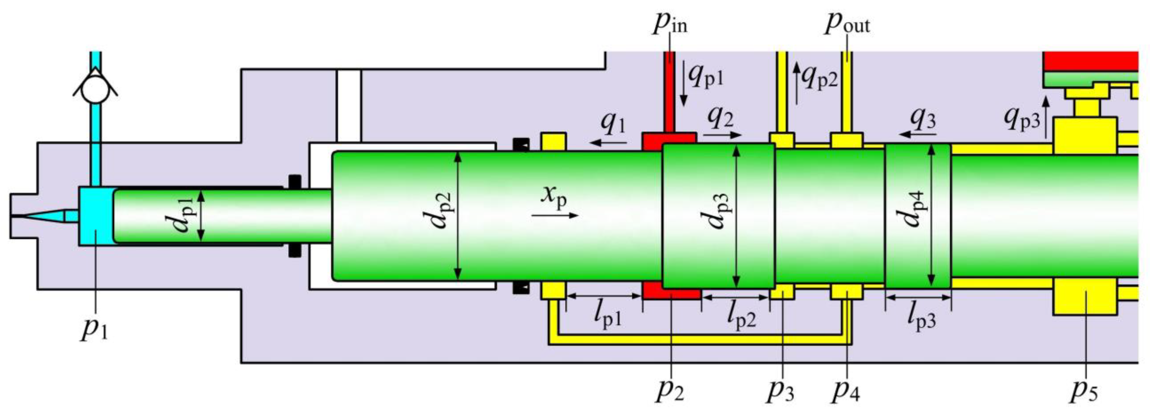
3.2.1. Dynamic Equation of the Piston

The force status of the piston and the flow and leakage of the hydraulic oil are shown in Figure 3.
Taking the piston moving to the right as positive, the dynamic equation of the piston can be expressed as
m p x ¨ p = π 4 d p 1 2 p 1 + π 4 ( d p 3 2 d p 2 2 ) p 2 π 4 d p 4 2 p 5
p out = k x q out 2 + k y q out 2 A y 2
where mp is the mass of the piston; xp is the displacement of the piston; pout is the outlet pressure; qout is the outlet flow rate; kx is the coefficient related to the pipeline resistance and fluid properties; ky is the coefficient related to the resistance generated by the throttle valve and fluid properties; and Ay is the overflow area of the throttle valve. When the piston backward strokes, we have p1 = p0, p2 = pin, and p5 = pout, where p0 is the water inlet pressure and pin is the oil inlet pressure. When the piston strokes, we have p1 = pw and p2 = p5 = pin.

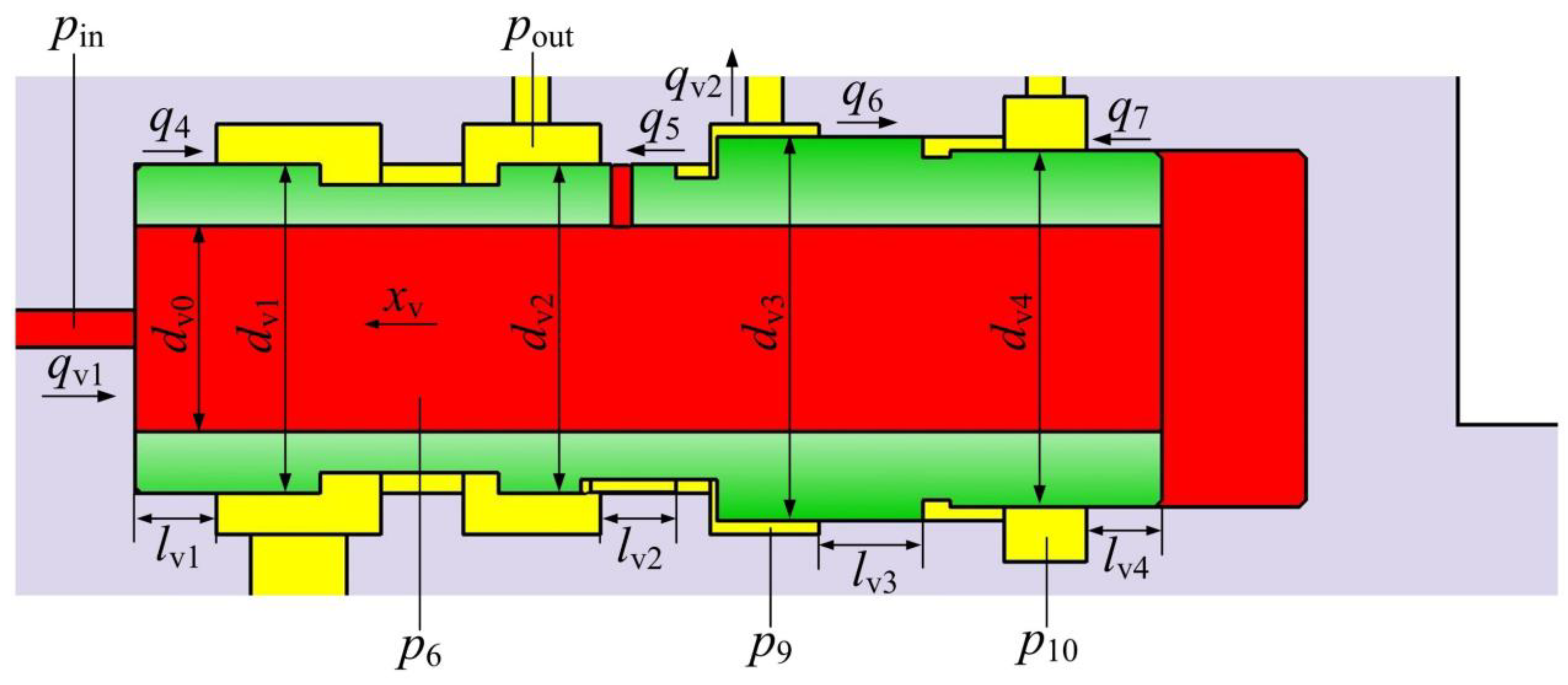
3.2.2. Dynamic Equation of the Valve Core

The force status of the valve core and the flow and leakage of the hydraulic oil are shown in Figure 4.
Taking the valve core moving to the left as positive, the dynamic equation of the valve core can be expressed as
m v x ¨ v = π 4 ( d v 4 2 d v 0 2 ) p 6 + π 4 ( d v 3 2 d v 4 2 ) p 10 π 4 ( d v 3 2 d v 2 2 ) p 9 π 4 ( d v 1 2 d v 0 2 ) p 6
where mv is the mass of the valve core and xv is the displacement of the valve core. When the valve core moves to the right, we have p6 = p9 = pin and p10 = pout; when the valve core moves to the left, we have p6 = pin and p9 = p10 = pout.

3.2.3. The Flow Rate Continuity Equation

Taking the oil compression and leakage into consideration, the flow continuity equation can be expressed as
{ V 2 + π 4 ( d p 3 2 d p 2 2 ) x p K e d p 2 d t = q p 1 π 4 ( d p 3 2 d p 2 2 ) x ˙ p C q p 2 q 1 q 2 V 5 π 4 d p 4 2 x p K e d p 5 d t = π 4 d p 4 2 x ˙ p ( q p 3 q 3 ) V 6 + π 4 ( d v 4 2 d v 1 2 ) x v K e d p 6 d t = q v 1 π 4 ( d v 4 2 d v 1 2 ) x ˙ v q 4 q 7 V 9 π 4 ( d v 3 2 d v 2 2 ) x v K e d p 9 d t = π 4 ( d v 3 2 d v 2 2 ) x ˙ v ( q v 2 q 5 q 6 )
{ q 1 = π d p 2 δ p 1 3 12 μ l p 1 ( p 2 p out ) q 2 = π d p 3 δ p 2 3 12 μ l p 2 ( p 2 p out ) q 3 = π d p 4 δ p 3 3 12 μ l p 3 ( p 5 p out ) q 4 = π d v 1 δ v 1 3 12 μ l v 1 ( p 6 p out ) q 5 = π d v 2 δ v 2 3 12 μ l v 2 ( p 9 p out ) q 6 = π d v 3 δ v 3 3 12 μ l v 3 ( p 9 p out ) q 7 = π d v 4 δ v 4 3 12 μ l v 4 ( p 10 p out )
where V2 and V5 are, respectively, the initial volume of chamber 2 and chamber 5 when the piston is in the left position; V6 and V9 are, respectively, the initial volume of chamber 6 and chamber 9 when the valve core is in the left position, and V2 = V6; Ke is the hydraulic oil bulk modulus; qp1, qp2, qv1, and qv2 are, respectively, the flow rate of chamber 2, chamber 3, chamber 6, and chamber 9; C is the state judgment quantity, and when chamber 2 and chamber 3 are connected, C = 1; otherwise, C = 0; qi is the leakage flow rate of the high-pressure chambers (i = 1, 2, 3, 4, 5, 6, 7); lpi and δpi are, respectively, the length and clearance of the matching surface between the piston and cylinder (i = 1, 2, 3); lvi and δvi are, respectively, the length and clearance of the matching surface between the valve core and cylinder (i = 1, 2, 3, 4); and μ is the hydraulic oil kinematic viscosity.

3.2.4. Simulation Parameters

As shown in Table 1, the values of the parameters used in the simulation models are set according to the actual dimension of the original PPWJ device or the measurement results.

3.3. Simulation Results

Taking the oil inlet pressure of 8 MPa as an example, the operational state of the device can be obtained by simulation. The displacement curves of the piston and valve core are shown in Figure 5a. The PPWJ is constructed by coupling the piston and the valve core, and they move back and forth at a limited displacement. When the piston backward strokes or is at the end of a stroke, the position of the valve core begins to switch. The volume and maximum displacement of the valve core are lower than those of the piston. The switch is completed in a short time, so the piston displacement curve is approximate to a sawtooth waveform. A temporary pause occurs when the valve core position switch is completed, and the displacement curve is approximate to a square waveform.
The velocity of the piston and the pressure of the jet are depicted in Figure 5b. During the backward stroke of the piston, the jet pressure equals the water inlet pressure. The jet pressure is pressurized during the piston stroke, and the increase, stability, and decrease in the jet pressure correspond to the acceleration, constant speed, and deceleration of the piston stroke, respectively. The jet pressure fluctuates periodically between high and low pressures and can provide a stable boosting effect during the uniform piston stroke.

3.4. Numerical Model Verification

The simulation results were compared with the experimental data from reference [35] under different operational parameters, and the corresponding results are illustrated in Figure 6. The curves of inlet pressure, jet pressure, and outlet pressure profiles observed in the experiment corresponded closely with the simulation results, thereby confirming the accuracy of the simulation. The experimental results show that in the initial stage of jet pressurization, i.e., the stroke acceleration stage of the piston, the actual pulse pressure curves fluctuated within a certain range. In this process, the system transformed from a transient state to a steady state, and the system load changed violently, which leads to the vibration of the valve core of the relief valve and causes the oil inlet pressure to fluctuate. The pressure fluctuation gradually decreased when the system transformed from a transient state to a steady state. However, the relief valve model provided by the simulation software library is too simple to truly reflect the transient process of the sudden changes in pressure and flow rate. The transformation process is so short that the local pressure fluctuation has little effect on the overall trend of the curves, and the influence of valve core vibration was ignored in the simulation model. Therefore, the pressure curves obtained by the simulation were relatively smooth.
Figure 6a,b illustrates some of the results at maximum throttle opening and varying oil inlet pressures. Increasing the oil inlet pressure not only amplifies the pulse pressure but also accelerates the backward stroke speed of the piston, leading to a reduction in the reciprocation period and an increase in pulse frequency. The diameter and length of the oil-return pipeline result in the occurrence of a certain outlet pressure during the backward stroke stage of the piston, while the outlet pressure in the stroke stage of the piston is nearly zero. Figure 6c,d illustrates some of the results at constant oil inlet pressure and different throttle openings. As the throttle openings decrease, the piston’s stroke speed remains constant, but the backward stroke diminishes. Consequently, the backward stroke time of the piston increases, resulting in a decrease in pulse frequency.

4. Effect of Key Structural Parameters of the PPWJ Device on Jet Characteristics

From Equations (9)–(12), it was found that the pulse parameters are affected by the structural parameters of the device, including nozzle diameter dn, piston maximum displacement h, and piston diameter dp1, dp2, and dp3. As listed in Table 2, these parameters were varied in the simulation model to evaluate the characteristics of the PPWJ. The operational parameters were constant, while the maximum input flow rate, maximum input pressure, and throttle opening were set to 30 L/min, 12 MPa, and 1, respectively. The simulation results of jet characteristics under different structural parameters can be obtained.

4.1. Effect of Nozzle Diameter dn

Figure 7 shows the relationship between the jet characteristics and nozzle diameter dn. When dn is smaller than 0.5 mm, the pulse pressure remains constant at 74 MPa, indicating that the oil inlet pressure equals the maximum input pressure. qsin increases with dn, leading to an increase in vsp, which in turn results in a higher pulse frequency and a shorter pulse duration. qsin is limited by the system’s rated flow rate; once dn surpasses 0.5 mm, the pulse pressure drops rapidly, and qsin reaches its peak and remains steady. This implies that vsp will remain unchanged, and the pulse frequency and pulse duration are likely to remain constant. dn is a critical factor influencing the rock breaking ability of a jet. It was found that increasing dn will increase the jet diameter. Meanwhile, the duration of the impact stress by the jet will be longer, and the area of the impact stress will increase. Due to the increased impact energy of the jet, the rock surface is more susceptible to damage, leading to a reduction in the threshold pressure for rock breaking [12,34,35,36,37,38,39,40,41,42,43,44,45,46]. Therefore, an appropriate increase in the dn is beneficial for improving rock breaking efficiency.

4.2. Effect of Piston Maximum Displacement h

Figure 8 shows the relationship between the jet characteristics and piston maximum displacement h. The pulse pressure remains constant if the piston can complete its acceleration and enters a uniform motion state within a limited maximum displacement. When h increases from 20 mm to 55 mm, the pulse frequency decreases slowly from 8.33 Hz to 3.03 Hz, and the pulse duration increases linearly from 0.08 s to 0.22 s. The reciprocating motion speed of the piston is not affected by h. As h increases, both tr and ts become longer, which leads to a decrease in pulse frequency.

4.3. Effect of Piston Diameter dp3

dp3 is the maximum outer diameter of the piston, and the relationship between the jet characteristics and dp3 is shown in Figure 9. When dp3 increases from 57 mm to 78 mm, the pulse frequency decreases slowly from 5.26 Hz to 2.94 Hz, but the pulse pressure and pulse duration remain constant. Increasing dp3 will increase the action area of the piston in chamber 2. Then, vrp will decrease, which results in a longer tr. The piston stroke stage remains unaffected by dp3, in line with the theoretical analysis results. Therefore, the decrease in the pulse frequency is caused by the longer tr. Reducing dp3 can not only increase the pulse frequency but also reduce the maximum outer diameter of the piston and the inner diameter of the cylinder matched with it. In this case, the device will be downsized in order to maintain its pressure-bearing capacity. Given the constraints of the seal ring on the piston’s maximum motion velocity, the optimal value of dp3 depends on the determination of dp2.

4.4. Effect of Piston Diameter dp1 and dp2

Piston diameters dp1 and dp2 are important parameters that affect the jet performance, the boost ratio (square of the ratio of dp2 to dp1), and the action area of the piston. The relationship between the jet characteristics and the variable boost ratio can be obtained by changing dp1 while keeping dp2 constant. As shown in Figure 10, with an increase in boost ratio, the pulse pressure increases from 43.9 MPa to 73.1 MPa and then falls to 10.8 MPa, and the maximum pulse pressure corresponds to a boost ratio of 6.25. When the boost ratio is lower than 6.25, the oil inlet pressure is equal to the value set by the throttle valve. Increasing the boost ratio will increase the pulse pressure, and vsp will be improved accordingly. vrp is not affected by dp1, so the pulse frequency will increase and the pulse duration will decrease. However, qsin is limited by the rated flow rate of the pump. When the boost ratio exceeds 6.25, qsin reaches the maximum value. In this case, increasing the boost ratio will decrease the pulse pressure. Meanwhile, vsp will not be improved, and the pulse frequency and pulse duration tend toward a stable value. For a certain nozzle diameter, there must be a value of boost ratio to maximize the pulse pressure.
Figure 11 shows the relationship between the jet characteristics and the action area of the piston in the case where the boost ratio is a constant of 6.25 and dp1 and dp2 are changed simultaneously. Meanwhile, the action area of the piston in chamber 2 is set to a fixed value to eliminate the influence of dp3 on the pulse frequency. If dp2 is less than 40 mm, it is apparent that the pulse pressure will not reach the maximum value of 73.1 MPa. Although the mass of the piston decreases with the decrease in dp2, a larger vsp is needed to make the pulse pressure reach the peak; otherwise, the piston is unable to achieve full acceleration within the limited maximum displacement. When dp2 exceeds 40 mm, the pulse pressure reaches the peak value and continues for a period of time, which indicates that the piston completes acceleration and enters the uniform motion state. There is a minimum value of dp1 and dp2 to make the pulse pressure reach the peak value when the boost ratio and maximum displacement are determined.

5. Performance Optimization of the PPWJ Device

5.1. Optimization Process

The dynamic characteristics of the PPWJ device and the pressure variation of the system can be predicted accurately by the established simulation model. According to the simulation results, the influence of the key structural parameters on the jet characteristic parameters is obtained, which is fundamental for the performance optimization of the device. The rational selection of structural parameters is beneficial for improving the efficiency of rock breaking; the optimization process mainly includes variable selection, objective function, and constraint condition.

5.1.1. Design Variable

On the premise of determining the rated parameters of the pump source, the parameters affecting the device performance are nozzle diameter, piston maximum displacement, and piston diameters dp1, dp2 and dp3, which are written in vector form:
X = [ d n h p d p 1 d p 2 d p 3 ] T

5.1.2. Objective Function

To improve the efficiency of rock breaking by the PWJ, it is first necessary to ensure that the pulse pressure reaches the threshold pressure for rock breaking, and then the nozzle diameter and maximum pulse frequency of the jet are adjusted accordingly.
p w p t
d n     max
f     max
where pt is the threshold pressure; threshold pressures corresponding to different types of rocks are different. Usually used as the research object of water jets for rock breaking, the threshold pressure of granite is 80 MPa [39].

5.1.3. Constraint Condition

The hydraulic pump is rated at 15 MPa, and the oil inlet pressure must not exceed 14 MPa due to pressure loss from the hydraulic oil during flow. To minimize wear on dynamic seals, the piston movement speed should be kept below 1 m/s. Considering manufacturing challenges, the length to diameter ratio of the cylinder’s inner hole should be less than 6.
p in 14 MPa
| d x p d t | 1 m / s
L d p 2 6
where L is the inner hole length of the cylinder.

5.1.4. Optimization Criteria

Firstly, the peak value of pulse pressure is the most important. Only when the peak value of pulse pressure reaches the threshold pressure of rock breaking, the stress wave effect of pulsed water jet will cause the macroscopic damage of rock.
Secondly, the nozzle diameter determines the energy contained in the pulse jet, and the magnitude of the jet energy determines the degree of rock breaking. The higher the energy applied to the rock per unit time during rock breaking, the greater the degree of rock breaking. Under the condition of not changing the peak pressure of the pulse, there exists an optimal value for the nozzle diameter, which maximizes the output power of a single pulse.
Finally, the pulse frequency reflects the number of jet impacts per unit time, and a high pulse frequency is more likely to aggravate the rock breaking.

5.1.5. Optimization Results

In summary, the problem is an optimal design problem with five design variables, three objective functions, and three inequality constraints. According to the simulation results, the optimized structural parameters are X = [0.51 27 18 44 51]T, and the structural parameters selected in the original design scheme are X = [0.45 35 22 53 60]T.
The comparison of the jet pressure curves before and after optimization is shown in Figure 12. Before optimization, the pulse pressure, nozzle diameter, and pulse frequency are 80 MPa, 0.45 mm, and 3.45 Hz. After optimization, the pulse cycle is shortened by 0.15 s, the pulse frequency is increased by 7.14 Hz, and the nozzle diameter is increased by 0.06 mm. In addition, the maximum outer diameter of the piston is reduced by 9 mm and the volume is reduced by 33.4%.

5.2. Experiment on Rock Breaking by PPWJ

5.2.1. Experimental Apparatus and Procedures

The experiments were carried out using our team’s independently developed four-dimensional water jet platform, with the PPWJ device and rock holder secured on the platform as depicted in Figure 13. As a representative of hard rock, granite was used in this work; for the convenience of fixing, the rock samples were processed into standard 100 mm × 100 mm × 100 mm (±1 mm) cube specimens with a cutting machine.
The pulse pressure, stand-off distance, and erosion time were set to be 80 MPa, 100 mm, and 5 min, respectively, in accordance with the results from the original PPWJ device for granite erosion in Ref. [38]. The nozzle was adjusted to align with the center of the rock surface after setting the standoff distance. A rigid baffle was inserted between the nozzle and rock sample to ensure a stable pulse pressure. Once the pulse pressure reached the set value and remained steady, the baffle was swiftly removed. After the experiment, a high-precision 3D topography scanner (Chotest, Shenzhen, China) was used to scan the samples, and 3D point cloud data was obtained and imported into Solidworks software (v2021) to reconstruct the erosion pit image, at which point the diameter and volume of erosion pit could be extracted.

5.2.2. Results and Discussion

The comparison of jet erosion on granite by the original device and the optimized device is shown in Figure 14. Under the action of the jet generated by the optimized device, the diameter of formed erosion pit Dp is 53 mm and the volume Vp is 2.44 mm3, which are 1.4 and 1.5 times those of the erosion pit formed by the jet generated by the original device, respectively. As the nozzle diameter increases, the high-pressure water flow through the nozzle grows, which will make more energy act on the rock without reducing pulse pressure. In addition, as the pulse frequency increases, the rock is subjected to greater impact, resulting in the generation of higher momentary pressures on the rock surface and transmitting stress waves into the rock interior. Therefore, at a constant pulse pressure, the increase in nozzle diameter and pulse frequency is conducive to producing more intensive rock breakage, and thus verified the feasibility of the optimization method.
The analysis of the simulation results can provide support for the optimization of the structural parameters of the PPWJ device. However, the research on the structure of the PPWJ device and its application in rock breaking is still in the exploratory and experimental stages. Regardless of the mechanical properties of the rock, it is confirmed that increasing the nozzle diameter and pulse frequency can improve rock breaking efficiency. On the one hand, some other hydraulic parameters are associated with rock breaking efficiency such as stand-off distance, erosion time, and erosion angle, and still need more work. On the other hand, the thermal effects and friction effects were not considered in theoretical analysis and simulation, which will be further improved in the future research.

6. Conclusions

  • The simulation model of a jet-generation system was constructed, and the motion laws of the piston and reversing spool and the evolution characteristics of the inlet pressure and jet pressure were analyzed. The piston and valve core move reciprocally in a limited stroke. There is a short pause when the reversal of the valve core is completed, and the displacement curve is approximately trapezoidal. There is no pause during the movement of the piston, and the displacement curve is approximately sawtooth-shaped. The pressure state of the jet corresponds to the motion state of the piston one by one. The low-pressure stage and boosting stage of the jet correspond to the backward stage and stroke stage of the piston, respectively.
  • The effect of the key structural parameters of the device on jet characteristics was analyzed. When the nozzle diameter or boost ratio exceeds a certain value, the pulse pressure drops and the pulse duration and pulse frequency no longer change; there is an optimal nozzle diameter or boost ratio to maximize the pulse pressure and pulse frequency. In addition, with the increase in piston maximum displacement or piston diameter dp2, the pulse duration increases and pulse frequency decreases. When the piston maximum displacement or piston diameter dp2 is lower than a certain value, the pulse pressure decreases. In addition, pulse pressure is not affected by piston diameter dp3; the increase in piston diameter dp3 results in the increase in pulse duration and decrease in pulse frequency.
  • The design criterion of the key structural parameters of the generator was established, and the optimal parameters were obtained based on the design criterion and simulation results. Compared with the original device, both the pulse frequency and output energy of the jet generated by the optimized device are significantly improved without reducing the pulse pressure. The rock breaking test results show that the diameter and volume of the granite erosion pit generated by the optimized device are 1.4 and 1.5 times those generated by the original device, respectively.

Author Contributions

Conceptualization, investigation, methodology, writing—original draft, Y.L.; Funding acquisition, supervision, software, visualization, X.W.; Data curation, formal analysis, project administration, resources, validation, J.T. All authors have read and agreed to the published version of the manuscript.

Funding

The work is jointly supported by the National Natural Science Foundation of China (U1804145) and the Scientific and Technological Breakthroughs Project of Henan Province (NO. 242102220062).

Institutional Review Board Statement

Not applicable.

Informed Consent Statement

Not applicable.

Data Availability Statement

The datasets used or analyzed during the current study are available from the corresponding author on reasonable request.

Acknowledgments

We would like to thank research participant Yangkai Zhang for writing—review and editing.

Conflicts of Interest

The authors have no conflicts of interest to declare that are relevant to the content of this article.

References

  1. Guha, A.; Ronald, R.M.; Balachandar, R. An experimental and numerical study of water jet cleaning process. J. Mater. Process. Technol. 2011, 211, 610–618. [Google Scholar] [CrossRef]
  2. Flower, G.; Pashby, I.R.; Shipway, P.H. The effect of particle hardness and shape when abrasive water jet milling titanium alloy Ti6Al4V. Wear 2009, 266, 613–620. [Google Scholar]
  3. Muruganandhan, R.; Mugilvalavan, M.; Thirumavalavan, K.; Yuvaraj, N. Investigation of water jet peening process parameters on AL6061-T6. Surf. Eng. 2018, 34, 330–340. [Google Scholar] [CrossRef]
  4. Cheng, J.L.; Jiang, Z.H.; Han, W.F.; Li, M.L.; Wang, Y.X. Breakage mechanism of hard-rock penetration by TBM disc cutter after high pressure water jet precutting. Eng. Fract. Mech. 2020, 240, 107320. [Google Scholar] [CrossRef]
  5. He, L.; Liu, Y.; Shen, K.; Yang, X.; Ba, Q.; Xiong, W. Numerical research on the dynamic rock breaking process of impact drilling with multi-nozzle water jets. J. Pet. Sci. Eng. 2021, 207, 109145. [Google Scholar] [CrossRef]
  6. Jiang, T.; Huang, Z.; Li, J.; Li, H. Effect of parameters on threshold pressure of sandstone tested by water jet. Int. J. Rock Mech. Min. Sci. 2021, 207, 109145. [Google Scholar] [CrossRef]
  7. Lu, Y.; Xiao, S.; Ge, Z.; Zhou, Z.; Ling, Y.; Wang, L. Experimental study on rock breaking performance of water jets generated by self-rotatory bit and rock failure mechanism. Powder Technol. 2019, 346, 203–216. [Google Scholar] [CrossRef]
  8. Xue, Y.; Si, H.; Yang, Z.; Xu, D. Microscopic damage field in coal induced by water jets. J. Loss Prev. Process Ind. 2018, 56, 300–315. [Google Scholar] [CrossRef]
  9. Xiao, S.; Ren, Q.; Cheng, Y.; Zhao, H.; Cao, S.; Zhang, L.; Chen, B.; Meng, X. Damage and fracture characteristics of rocks with different structures under high-velocity water jet impact. Eng. Fract. Mech. 2021, 256, 107961. [Google Scholar] [CrossRef]
  10. Lu, Y.; Huang, F.; Liu, X.; Ao, X. On the failure pattern of sandstone impacted by high-velocity water jet. Int. J. Impact Eng. 2015, 76, 67–74. [Google Scholar] [CrossRef]
  11. Momber, A.W. The response of geo-materials to high-speed liquid drop impact. Int. J. Impact Eng. 2016, 89, 83–101. [Google Scholar] [CrossRef]
  12. Xue, Y.; Si, H.; Hu, Q. The propagation of stress waves in rock impacted by a pulsed water jet. Powder Technol. 2017, 320, 179–190. [Google Scholar] [CrossRef]
  13. Abulimiti, A.; Zheng, C.; Liu, Y.; Pang, H.; Pang, D.; Anwaier, M.; Guo, X. Study on the impacting performance of a self-excited oscillation pulsed jet nozzle. J. Pet. Sci. Eng. 2021, 207, 109120. [Google Scholar] [CrossRef]
  14. Li, D.; Kang, Y.; Wang, X.; Ding, X.; Fang, Z. Effects of nozzle inner surface roughness on the cavitation erosion characteristics of high speed submerged jets. Exp. Therm. Fluid Sci. 2016, 74, 444–452. [Google Scholar] [CrossRef]
  15. Li, D.; Kang, Y.; Ding, X.; Wang, X.; Fang, Z. Effects of area discontinuity at nozzle inlet on the characteristics of high speed self-excited oscillation pulsed waterjets. Exp. Therm. Fluid Sci. 2016, 79, 254–265. [Google Scholar] [CrossRef]
  16. Li, D.; Kang, Y.; Ding, X.; Wang, X.; Liu, W. Effects of feeding pipe diameter on the performance of a jet-driven Helmholtz oscillator generating pulsed waterjets. J. Mech. Sci. Technol. 2017, 31, 1203–1212. [Google Scholar] [CrossRef]
  17. Zhou, Z.; Ge, Z.; Lu, Y.; Zhang, X. Experimental study on characteristics of self-excited oscillation pulsed water jet. J. Vibroeng. 2017, 19, 1345–1357. [Google Scholar] [CrossRef]
  18. Zhang, X.; Li, X.; Nie, S.; Wang, L.; Dong, J. Study on velocity and pressure characteristics of self-excited oscillating nozzle. J. Braz. Soc. Mech. Sci. Eng. 2021, 43, 5. [Google Scholar] [CrossRef]
  19. Liu, W.; Kang, Y.; Zhang, M.; Wang, X.; Li, D. Self-sustained oscillation and cavitation characteristics of a jet in a Helmholtz resonator. Int. J. Heat Fluid Flow 2017, 68, 158–172. [Google Scholar] [CrossRef]
  20. Liu, W.; Kang, Y.; Zhang, M.; Wang, X.; Li, D.; Xie, L. Experimental and theoretical analysis on chamber pressure of a self-resonating cavitation waterjet. Ocean Eng. 2018, 151, 33–45. [Google Scholar] [CrossRef]
  21. Liu, W.; Kang, Y.; Wang, X.; Liu, Q.; Fang, Z. Integrated CFD-aided theoretical demonstration of cavitation modulation in self-sustained oscillating jets. Appl. Math. Model. 2020, 79, 521–543. [Google Scholar] [CrossRef]
  22. Kolsek, T.; Jelic, N.; Duhovnik, J. Numerical study of flow asymmetry and self-sustained jet oscillations in geometrically symmetric cavities. Appl. Math. Model. 2007, 31, 2355–2373. [Google Scholar] [CrossRef]
  23. Szada-Borzyszkowska, M.; Kacalak, W.; Banaszek, K.; Pude, F.; Perec, A.; Wegener, K.; Królczyk, G. Assessment of the effectiveness of high-pressure water jet machining generated using self-excited pulsating heads. Int. J. Adv. Manuf. Technol. 2024, 133, 5029–5051. [Google Scholar] [CrossRef]
  24. Vijay, M.M.; Foldyna, J. Ultrasonically modulated pulsed: Basic study. In Proceedings of the 12th International Conference on Jet Cutting Technology, Rouen, France, 25–27 October 1994; Volume 13, pp. 15–35. [Google Scholar]
  25. Foldyna, J.; Sitek, L.; Švehla, B.; Švehla, Š. Utilization of ultrasound to enhance high-speed water jet effects. Ultrason. Sonochem. 2004, 11, 131–137. [Google Scholar] [CrossRef] [PubMed]
  26. Zelenak, M.; Foldyna, J.; Scucka, J.; Hloch, S.; Riha, Z. Visualisation and measurement of high-speed pulsating and continuous water jets. Measurement 2015, 72, 1–8. [Google Scholar] [CrossRef]
  27. Tripathi, R.; Hloch, S.; Chattopadhyaya, S.; Klichová, D.; Ščučka, J.; Das, A.K. Application of the pulsating and continous water jet for granite erosion. Int. J. Rock Mech. Min. Sci. 2020, 126, 126. [Google Scholar] [CrossRef]
  28. Říha, Z.; Zeleňák, M.; Kruml, T.; Poloprudský, J. Comparison of the disintegration abilities of modulated and continuous water jets. Wear 2021, 478–479, 203891. [Google Scholar] [CrossRef]
  29. Raj, P.; Hloch, S.; Tripathi, R.; Srivastava, M.; Nag, A.; Klichová, D.; Klich, J.; Hromasová, M.; Muller, M.; Miloslav, L.; et al. Investigation of sandstone erosion by continuous and pulsed water jets. J. Manuf. Process 2019, 42, 121–130. [Google Scholar] [CrossRef]
  30. Tripathi, R.; Hloch, S.; Chattopadhyaya, S.; Klichová, D.; Klich, J. Influence of frequency during sandstone erosion by pulsed waterjet. Mater. Manuf. Process 2020, 35, 187–194. [Google Scholar] [CrossRef]
  31. Srivastava, M.; Hloch, S.; Tripathi, R.; Kozak, D.; Chattopadhyaya, S.; Dixit, A.R.; Foldyna, J.; Hvizdos, P.; Fides, M.; Adamcik, P. Ultrasonically generated pulsed water jet peening of austenitic stainless-steel surfaces. J. Manuf. Process 2018, 32, 455–468. [Google Scholar] [CrossRef]
  32. Hloch, S.; Adamčík, P.; Nag, A.; Srivastava, M.; Čuha, D.; Müller, M.; Hromasová, M.; Klich, J. Hydrodynamic ductile erosion of aluminium by a pulsed water jet moving in an inclined trajectory. Wear 2019, 428–429, 178–192. [Google Scholar] [CrossRef]
  33. Jiang, H.; Liu, Z.; Gao, K. Numerical simulation on rock fragmentation by discontinuous water-jet using coupled SPH/FEA method. Powder Technol. 2017, 312, 248–259. [Google Scholar] [CrossRef]
  34. Polyakov, A.; Zhabin, A.; Averin, E.; Polyakov, A. Generated equation for calculating rock cutting efficiency by pulsed water jets. J. Rock Mech. Geotech. Eng. 2019, 11, 867–873. [Google Scholar] [CrossRef]
  35. Pan, Y.; Yang, F.; Zhang, Z.P.; Ma, H. Numerical simulation of coal rock fragmentation characteristics under interrupted pulse water jet. J. Vib. Shock. 2021, 40, 283–288. [Google Scholar]
  36. Dehkhoda, S.; Hood, M. An experimental study of surface and sub-surface damage in pulsed water-jet breakage of rocks. Int. J. Rock Mech. Min. Sci. 2013, 63, 138–147. [Google Scholar] [CrossRef]
  37. Dehkhoda, S.; Hood, M. The internal failure of rock samples subjected to pulsed water jet impacts. Int. J. Rock Mech. Min. Sci. 2014, 66, 91–96. [Google Scholar] [CrossRef]
  38. Liu, Y.; Wei, J.; Ren, T.; Lu, Z. Experimental study of flow field structure of interrupted pulsed water jet and breakage of hard rock. Int. J. Rock Mech. Min. Sci. 2015, 78, 253–261. [Google Scholar] [CrossRef]
  39. Lu, Z.; Lu, Y.; Hood, M.; Pan, L.; He, P. Numerical simulation and analysis on the flow field structure and hard rock erosion potential of a disc-slotted pulse water jet. J. Vib. Shock. 2017, 36, 180–185. [Google Scholar]
  40. Kang, Y.; Wang, X.; Li, D.; Shi, H. Effects of modulation position on the impact performance of mechanically modulated pulsed water jet. J. Manuf. Process. 2020, 56, 510–521. [Google Scholar]
  41. Zhu, D.; Yu, B.; Wang, D.; Zhang, Y. Fusion of finite element and machine learning methods to predict rock shear strength parameters. J. Geophys. Eng. 2024, 21, 1183–1193. [Google Scholar] [CrossRef]
  42. Ling, Y.; Ge, Z.; Tang, J.; Lu, Y.; Zhang, Y.; Wang, L. Development of a pressurized pulsed water jet device and its application potential for hard rock breaking. Rev. Sci. Instrum. 2021, 92, 085101. [Google Scholar] [CrossRef]
  43. Chiatto, M.; Capuano, F.; Coppola, G.; De Luca, L. LEM Characterization of Synthetic Jet Actuators Driven by Piezoelectric Element: A Review. Sensors 2017, 17, 1216. [Google Scholar] [CrossRef] [PubMed]
  44. Dehkhoda, S.; Hood, M.; Alehossein, H.; Buttsworth, D. Analytical and experimental study of pressure dynamics in a pulsed water jet device. Flow Turbul. Combust 2012, 89, 97–119. [Google Scholar] [CrossRef]
  45. Fox, R.W.; Pritchard, P.J.; McDonald, A.T. Introduction to Fluid Mechanics, 7th ed.; John Wiley & Sons, Inc.: New York, NY, USA, 2009. [Google Scholar]
  46. Kennedy, C.F.; Field, J.E. Damage threshold velocities for liquid impact. J. Mater. Sci. 2000, 35, 5331–5339. [Google Scholar] [CrossRef]
Figure 1. The structure and operational principle of the PPWJ device: (a) backward stroke state of the piston, (b) stroke state of the piston.
Applsci 14 06788 g001
Figure 2. Simulation model of the PPWJ system.
Applsci 14 06788 g002
Figure 3. The motion state of the piston.
Applsci 14 06788 g003
Figure 4. The motion state of the valve core.
Applsci 14 06788 g004
Figure 5. The operational state curves of the PPWJ device: (a) displacement curves of the valve core and piston, (b) piston velocity and jet pressure curves.
Applsci 14 06788 g005
Figure 6. Comparison of the pressure curves obtained by simulation and experiment: (a) inlet pressure: 2 MPa, throttle opening: 1, (b) inlet pressure: 14 MPa, throttle opening: 1, (c) inlet pressure: 8 MPa, throttle opening: k1, (d) inlet pressure: 8 MPa, throttle opening: k2.
Applsci 14 06788 g006
Figure 7. Jet characteristics versus nozzle diameter: (a) variation of jet pressure curves, (b) variation of pulse parameters.
Applsci 14 06788 g007
Figure 8. Jet characteristics versus piston maximum displacement: (a) variation of jet pressure curves, (b) variation of pulse parameters.
Applsci 14 06788 g008
Figure 9. Jet characteristics versus piston diameter dp3: (a) variation of jet pressure curves, (b) variation of pulse parameters.
Applsci 14 06788 g009
Figure 10. Jet characteristics versus piston diameter dp1: (a) variation of jet pressure curves, (b) variation of pulse parameters.
Applsci 14 06788 g010
Figure 11. Jet characteristics versus piston diameters dp1 and dp2: (a) variation of jet pressure curves, (b) variation of pulse parameters.
Applsci 14 06788 g011
Figure 12. Comparison of the jet curves before and after optimization.
Applsci 14 06788 g012
Figure 13. Experimental system of rock breaking by PPWJ.
Applsci 14 06788 g013
Figure 14. Granite erosion pit by the jet generated by (a) original device [35], (b) optimized device.
Applsci 14 06788 g014
Table 1. Parameters used in the simulation models.
ParametersValueParametersValue
Piston outer diameter dp1 (mm)22Valve core outer diameter dv2 (mm)24
Piston outer diameter dp2 (mm)53Valve core outer diameter dv3 (mm)28
Piston outer diameter dp3 (mm)60Valve core outer diameter dv4 (mm)26
Piston outer diameter dp4 (mm)60Valve core maximum displacement hv (mm)10
Piston maximum displacement hp (mm)35Rated flow rate of the pump qr (L/min)30
Nozzle diameter dn (mm)0.45Water inlet pressure p0 (MPa)0.3
Nozzle discharge coefficient Cd0.95Hydraulic oil viscosity μ (mm2/s)48
Valve core inner diameter dv0 (mm)15Hydraulic oil bulk modulus Ke (MPa)1200
Valve core outer diameter dv1 (mm)24Water density ρw0 (kg/m3)1000
Table 2. The structural parameters used in the simulation model.
Structural ParametersInitial ValueValue RangeGradient
Nozzle diameter dn (mm)0.50.35–0.70.05
Piston maximum displacement h (mm)3520–555
Piston diameter dp3 (mm)6057–783
Variable diameter ratio dp1/dp220/5012–26/50–502/0
Fixed diameter ratio dp1/dp220/508–36/20–904/10
Disclaimer/Publisher’s Note: The statements, opinions and data contained in all publications are solely those of the individual author(s) and contributor(s) and not of MDPI and/or the editor(s). MDPI and/or the editor(s) disclaim responsibility for any injury to people or property resulting from any ideas, methods, instructions or products referred to in the content.

