Article

Suboptimal Analysis of the Differential System of the Conceptual Trailer Air Brake Valve

1
Doctoral School, Bialystok University of Technology, 45A Wiejska Str., 15-351 Bialystok, Poland
2
Faculty of Mechanical Engineering, Bialystok University of Technology, 45C Wiejska Str., 15-351 Bialystok, Poland
*
Author to whom correspondence should be addressed.
Appl. Sci. 2024, 14(15), 6792; https://doi.org/10.3390/app14156792 (registering DOI)
Submission received: 12 July 2024 / Revised: 26 July 2024 / Accepted: 2 August 2024 / Published: 3 August 2024
(This article belongs to the Section Mechanical Engineering)

Abstract

:

Featured Application

The results are applicable to the configuration of design parameters of pneumatic brake valves. The proposed conceptual solution for the valve’s differential part has implementation potential. The analyses meet the trend of increasing the speed of pneumatic braking systems. Pneumatic systems, despite being slower than hydraulic systems, pose less environmental risk during use or failure.

Abstract

Motivation: To increase the efficiency of the brake valve by adding a corrective member. Background: The speed of response and smooth transition between modes of operation in the braking system are the primary research questions. Objective and research question: Will the optimal selection of the input parameters of the differentiating part of a conceptual brake valve ensure the speed of operation and enable a smooth transition from the accelerating mode to the tracking mode? Methods: The mathematical model of the differentiating part of the brake valve uses the lumped method, and the solution was obtained by numerical means. Results: Within the assumed range of variation of spring stiffness and control piston bore throughput, the distribution maps of action times and piston lift were determined, and the optimal configuration of the analyzed input parameters was obtained by a genetic algorithm. Future research: future activities will focus on the development of a system of smooth variation of the throughput of the connecting chamber of the differential part of the valve. Conclusions: The determined maps of functional parameter distributions are the basis for the selection of components of the braking system; optimization indicates the directions of modification of the valve in order to obtain an acceptable performance system.

1. Introduction

Vehicle and trailer air braking systems must meet the requirements set forth in UNECE Regulation No. 13 [1]. The provisions outlined there define the magnitudes of the control parameters that are the basis for approval and subsequent inspections during use. Although air braking systems are slower in operation relative to liquid systems [2], they are still popular on the market. The enthalpy of the working medium in the form of compressed air, also known as thermodynamic potential, is responsible for the operation of this system. The advantage of pneumatic systems over liquid ones is their environmental friendliness. Air, which is widely available, requires only compression and further appropriate distribution to controls and actuators. Any kind of connection or malfunction (except for the compressor, which is lubricated with oil) does not pose an ecological hazard. Agricultural tractors, semi-trailers, or trains are equipped with air brake control systems for trailers, semi-trailers, or working machines in various system configurations. The increase in the dimensions of convoys traveling on the road, including road or rail trains, creates the need to correct the speed of operation of the individual members of the convoys [3]. In addition, military operations and the need to transport combat equipment also intensify the scope of use of air braking systems. An important characteristic of any braking system, including air brakes, is a predictable response to the driver’s intentions. Hence the need for additional valves on the tractor–trailer valve–actuator line [4]. Forcing from the side of the vehicle towing the trailer should result in an intended response from the brake valves and operating actuators [5].
Depending on the target operating parameters and purpose, different types of trailer valves are used in air braking systems [6,7]. The system can function without a trailer valve, but its response to forcing, due to the volume of the system, will be prolonged and may be insufficient at the initial stage to realize full braking. Some of the most commonly used valves in trailer air braking systems are relay valves [8,9,10]. In operation, in addition to the control system, they use additional air reservoirs located close to the valve. A momentary override to the additional reservoir increases braking efficiency. This significantly reduces the response time of the brake actuators to driver forcing [11]. Such valves can perform a specific function without having the ability to smoothly transition between operating modes [12]. The lack of smooth transition between operating modes, which can be critical under varying forcing conditions, resulted in the proposal to use differential valves, which were discontinued in [13]. Although it has been a long time since the presentation of this paper, the differential valve still remains only in the area of scientific research. There are a number of studies of its use in brake systems with long control lines [14,15] demonstrating its applicability. Often, a valve of this type, due to cost reduction, is practically realized by modifying the design already existing on the market. As shown in W [16], the differential valve gives the driver the possibility to operate in a tracking mode or accelerating mode and smoothly transitions between modes, depending on the driver’s forcing. There are a number of post-medium solutions, such as various types of acceleration members mounted additionally in the valves [17], pneumatic-only combination valves [18], or electro-pneumatic valves [2]. It is the electro-pneumatic systems that are seen as the target for increasing the efficiency of trailer and work machinery braking systems, as confirmed by studies [19,20,21]. The increasing automation of vehicle driving requires the use of complex systems that work with already existing vehicle systems (ABS, BAS). In this case, as well as in other utility applications, systems that use a PWM signal to regulate operating pressure are proving their worth [11]. Electronically controlled air braking systems also have applications in autonomous vehicles, where performance and reliability criteria are tightened relative to conventional vehicles [22].
Computational analyses involving pneumatic braking systems can be divided into two groups: analytical–empirical modeling and modeling using CFD. In the first group, mainly empirical modeling creates its own mathematical descriptions of the components of the braking system [23], the solution of which is sought by numerical methods using Matlab–Simulink or AMESim [18]. In this group, there is a noticeable trend that exploits the discretization of the system into small, repeated alternating components, referred to as the lumped method [13]. This method is successfully used in the calculations of systems with relay valves [9] or differential valves [15]. In the analytical and empirical methods, a quantitative evaluation consisting of the determination of pressure waveforms in the components of the braking system is set as the goal. On this basis, the speed of response of the system or the course of the braking force is evaluated. In the second group of computational methods, those using CFD, it has become common to use dedicated software for 2D and 3D analysis, such as, for example, KIVA, Ansys Fluent, and others [24,25,26,27]. Due to the complexity of the flow process, the mathematical description here is based on Reynolds average Navier–Stokes methods (RANS) [28,29]. In addition to quantitative evaluation, CDF software allows for qualitative flow analysis. It is used as an alternative to experimental studies, which are expensive to set up and conduct and whose results are successfully used in the empirical modeling of entire systems [30]. A significant number of studies are directed at optimizing the design of pneumatic brake system components as well as process control using information from various sensors [31,32]. An analysis of the literature revealed a research gap related to the use of certain types of brake valve performance-correcting members. Based on this, it was deemed necessary to analyze a differential member that will be able to increase the efficiency of the brake valve.
The purpose of the analysis presented in the study was to evaluate the effect of spring stiffness and throughput of the piston bore of the differential part of the valve on its functional characteristics. It was decided to use the following methods and means for such a goal:
  • Propose the scope of modification of the existing brake valve necessary to realize the design of the conceptual differential valve;
  • Develop a mathematical model of the differentiating part of the valve and indicate how to solve it;
  • Carry out multivariate calculations to collect a group of results;
  • Based on the group of results, conduct a suboptimal functional analysis to determine the variant that meets the conditions set.
The rest of the paper is as follows: Section 2 describes the object of analysis, presents the mathematical model, the conditions necessary to initiate the calculations, and the solution method. Section 3 presents the results and discussion, dividing them into the determination of functional features and suboptimal functional analysis. A further section, Section 4, proposes future research. Conclusions are included in Section 5.

2. Materials and Methods

2.1. Object of Analysis

The realization of a conceptual brake valve with a differential part was decided by modifying a commercial solution of the Visteon trailer relay valve 44100110 (Figure 1a). In the original version, this valve can work with both single- and dual-line tractor braking systems. In the case of a single-line system, the connection M is connected to the power and control port (black line), while the connection Zm is left unconnected and sealed. In a two-line system, connector M connects to the power port (red line of the tractor connection), and Zm connects to the control port (yellow line of the tractor connection). In both systems, connection V connects to the trailer’s compressed air reservoir, and connection Z connects to the brake force regulator or directly to the actuator. A detailed description of the valve’s operation can be found in [12].
The extent of the modification of the Visteon trailer relay valve 44100110 is shown in Figure 1b,c. In the first step, the interlock a was removed from the upper body and the channel between the bodies b was plugged. In addition, the f and g connections M and Zm were blanked off. Necessary for the realization of the differential function was the drilling of a hole c in the piston and the permanent immobilization of the piston on the pusher d. The next step involved replacing the one-way seal e with a seal that works both ways. It was decided to use the vent W as a functional channel. Schematically, the conceptual valve is shown in Figure 1d.
When the control pressure pin (blue line in Figure 1b) feeding W and channel a builds up with a small gradient, the hole in the piston does not allow the pressure difference above and below the piston to be large enough to overcome the force coming from the spring. Then, the brake actuators, by connection Z, are supplied with a pressure pin in tracking mode. In the case of a large gradient pin, the piston is displaced, changing the supply to the actuators from connection W to V. The V connection is supplied from an additional reservoir close to the valve, so this mode is referred to as acceleration mode. Depending on the stiffness of the spring under the piston controlling the valve modes and the diameter of the hole in the piston, the timing of the appearance of the accelerating mode and its disappearance can be controlled. While accelerating action can be achieved with various valve configurations, such as a relay valve, guaranteeing a smooth transition to the tracking function is difficult. The basic problem of differential valve operation is the selection of the stiffness of the spring under the control piston and the diameter of the piston bore, which formed the basis of the analyses in this study.

2.2. Mathematical Model

The high complexity of the design of the entire valve (Figure 1) was the reason that only the differential part was analyzed in the following section. A number of simplifications had to be adopted in the development of the mathematical model. The most important of these include the following:
  • The mechanical system is perfectly rigid;
  • The pneumatic system is perfectly tight;
  • The position of the piston depends on the balance of forces acting in the system;
  • The air pressure is distributed uniformly in the volumes under analysis;
  • The state of the air in the volumes has a constant temperature and depends on time and the inlet–outlet mass balance;
  • The flow was considered isentropic in an adiabatic sheath;
  • The spring generates a force due to its stiffness and deflection and preload;
  • Friction depends on the movement of the piston and has different components;
  • Flow-limiting elements open and close gradually.
Functional, mechanic, and pneumatic schemes were created based on the adopted simplifications (Figure 2a,b).
The position of the piston controlling the action of the differential system (Figure 2a) is the result of forces of various origins, whose equilibrium state is written in the following form:
F p F s F f F m = 0 ,
where Fp—pressure force; Fs—spring force; Ff—friction force; and Fm—mass inertia drag force.
The force from the air pressure Fp depends on the pressure difference over pA (chamber A) and under the piston pB (chamber B). Due to the presence of a control pin, it was necessary to take into account the differences in surface areas under and over the piston.
F p = π D 2 4 p A π ( D 2 d 2 ) 4 p B ,
where D—piston diameter and d—piston rod diameter.
The air pressure over the piston pA was the result of the flow into chamber A from the inlet side, as well as the flow into and out of chamber B through the hole made in the piston. The lumped method [13,33] was used to calculate the pressures in the chambers. Differential equations describing the pressure changes in chambers A and B were constructed from the diagram (Figure 2b) and written as follows:
d p A d t = κ R T V A ( d m i n d t d m n o z d t p A R T d V A d t ) ,
d p B d t = κ R T V B ( d m o u t d t p B R T d V B d t ) ,
where κ—adiabatic exponent; R—air constant; T—air temperature; and VA and VB—volume A and B chambers, respectively.
The air mass fluxes flowing through the inlet local resistance (µA)in in and the piston bore local resistance (µA)noz are described by differential equations in the following forms:
d m i n d t = ( μ A ) i n v max ρ i n φ max ( σ ) f ( σ ) i n ,
d m n o z d t = ( μ A ) n o z v max ρ n o z φ max ( σ ) f ( σ ) n o z ,
where vmax—velocity of sound in a stationary gas v max = κ R T ; ρ—air density ρ i n = p i n / ( R T ) and ρ n o z = p A / ( R T ) ; φmax(σ)—maximum value of the theoretical flow function Saint-Venant and Wantzel φmax(σ) = 0.785; f(σ)—flow function (Miatluk-Avtushko [13] f ( σ ) = 1.13 1 σ 1.13 σ ), σ—pressure ratio σ = p i + 1 / p i .
The force from the spring Fs located in chamber B was calculated from the sum of the preload force and the variable force due to piston displacement and spring stiffness:
F s = F 0 + k h p ,
where F0—preload force; k—spring stiffness; hp—piston displacement.
The force resulting from the friction Fs of the piston seal against the valve housing is divided into two types, static Ffs and kinetic Ffk, depending on the movement of the piston or lack thereof.
F f = { F f s = μ s F N if h p = 0 , h p = h max F f k = μ k F N sgn ( h ˙ p ) if h p = var ,
where μs—static friction coefficients; μk—kinetic friction coefficients; and Fn—contact force.
The mass inertia drag force Fm was calculated from the following:
F m = m d 2 h p d t 2 ,
where m—piston and piston rod mass
Based on Equations (1)–(9), a system of differential equations was formed as follows:
{ d h p d t = v d v d t = F p F s F f m d p A d t = κ R T V A ( d m i n d t d m n o z d t p A R T d V A d t ) d p B d t = κ R T V B ( d m o u t d t p B R T d V B d t ) d m i n d t = ( μ A ) i n v max ρ i n φ max ( σ ) f ( σ ) i n d m n o z d t = ( μ A ) n o z v max ρ n o z φ max ( σ ) f ( σ ) n o z .
Among the range of optimization methods, such as grey wolf [34], whale [35], Harris hawks [36], body shape [37], particle swarm [38], game theory [39], and many others, the genetic algorithm (GA) was chosen [40]. The GA algorithm was designed to simulate biological processes, so biological terminology is used in its description. Although genetic algorithms may differ in details, they almost always have common components, which include the follow [41]:
  • Fitness function necessary for optimization;
  • Population of all chromosomes;
  • Selection from the population of chromosomes that will reproduce;
  • Crossing over chromosomes to produce the next generation of chromosomes;
  • Random mutation in the new generation of chromosomes.
The most important component of the algorithm is the fitness function, and from its notation the optimal solution is obtained. A chromosome is considered a numerical value that presents the solution to the problem. For a problem with N-pairs of dimensions, each chromosome is encoded as follows:
chromosome = [ p 1 , p 2 , , p N p a r ] ,
where p—particular value of the i-th parameter.
Each chromosome is evaluated with a fitness function in terms of problem solving. With a non-negative fitness function, the probability of selecting chromosome A11 for further reproduction can be calculated as follows:
P ( A 11 ) = | f ( A 11 ) i = 1 N p o p f ( A 11 ) | ,
The selection of the chromosome to be exchanged can repeat from the position of the operator, and the crossover and recombination resemble the phenomena found in biology. Disposing of parental chromosomes:
[ 1101011100   1000 ] and [ 0101110101   0010 ] ,
They can be crossed, for example, after the fourth bit, obtaining the following descendants:
[ 0101011100   1000 ] and [ 1101110101   0010 ] .
Furthermore, the second generation is tested by the fitness function and the process repeats itself, where evaluation and selection take place. Mutation prevents the optimization process from getting stuck in a local minimum. The algorithm runs until a solution is found that meets the termination criterion, which, in many cases, is a compromise between the stated requirements.
The use of the Matlab environment in GA optimization is common in a variety of issues, not only biological or medical, but also technical. It has been successfully used in the design of intelligent engineering systems [42], improving the efficiency of power grids [43] or the parameters of a solar cells [44].

2.3. Initial and Boundary Conditions

In order to initiate calculations enabling further analysis of the results, it was necessary to adopt initial and boundary conditions. With a real object at their disposal and a virtual model, a series of measurements and estimates of these values were made, the results of which are included in Table 1.
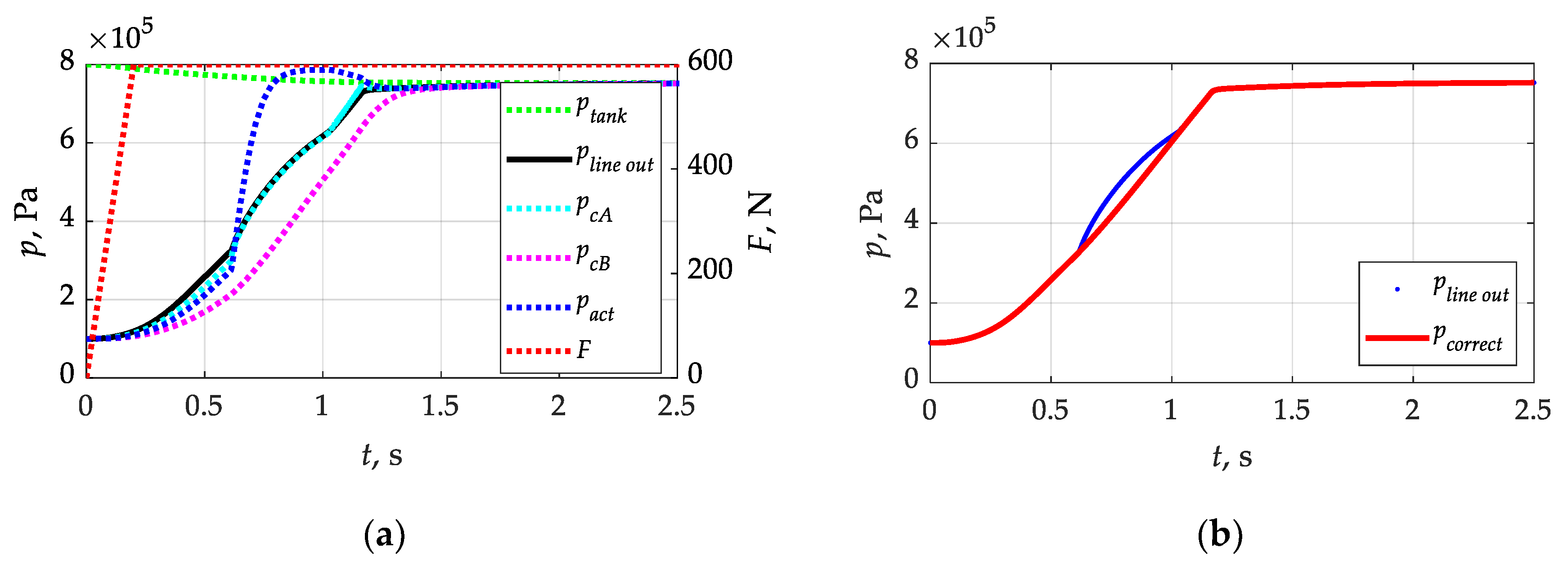
To initiate the calculations, it was necessary to assume the pressure waveform at the inlet to the trailer brake valve pin under analysis. For this purpose, the waveforms presented in [45] were used, where a constructurally similar valve in a braking system with a 20 m control and supply line was modeled. In Figure 3a, the individual waveforms denote the following: F—forcing force on the tractor’s brake valve; ptank—pressure in the tractor’s supply reservoir (without refilling with the compressor); pline_out—pressure at the end of the 20 m line connecting the tractor’s valve to the trailer’s brake valve; pcA and pcB—pressures in the valve chambers; and pact—pressure in the brake actuator. Having the waveforms contained in Figure 3a, a waveform pline_out was extracted from them, which represented the end of the 20 m supply line connecting the tractor valve and the trailer valve. In the simulations presented in [45], the brake valve in both the differentiating and transmitting parts operated in a stepwise manner. What was missing was an accurate representation of the movement of the actuators and the resulting changes in throughput. As shown in (Figure 3a), the pressure in the pact actuator reached 0.75 pmax in close to 0.6 s, which is consistent with the requirements included in the UNECE regulation No. 13 [1]. For the purpose of the realization of the calculations, this waveform was ‘smoothed’ in the part of the power supply change from the supply line to the additional trailer tank (Figure 3b). This resulted in a waveform pcorrect, which was implemented as pin in the calculations that were carried out, according to (Figure 2).

2.4. Method to Find a Solution

The system of differential Equation (10) was solved numerically using the implicit trapezoidal method with variable-step backward differentiation. Adjustment of the value of the input pressure waveform to the variable step of the numerical solution was achieved by interpolation using the cubic method with shape-preserving variation in the spring stiffness and piston bore capacity, which was achieved by combining code elements written in Matlab and a block functional diagram built in Simulink.

3. Results

3.1. Determination of Characteristic Operating Times and Maximum Displacement of the Valve Piston

Implemented in the Matlab–Simulink environment, the calculation procedures based on Equation (10) and Table 1 enabled the determination of pressure waveforms in the valve chambers, chamber volume changes, and piston displacement. Example waveforms are shown in Figure 4. The correlation of the pressure waveforms (Figure 4a) with the change in chamber volume (Figure 4b) and the displacement of the valve piston (Figure 4c) can be seen, which confirms the correctness of the adopted mathematical description and calculation methodology. At the point where the piston reaches its maximum displacement (hpmax), chamber A increases its volume to its maximum value (VAmax), the opposite of chamber B (VBmin). At the moment of actuation of the differential part of the valve pin, due to the proximity of chamber A and the relatively high value of the inlet capacity (μA)in, the course pA differs little from the course pin (Figure 4a). The initial increase in pressure in chamber B until the piston reaches maximum displacement hpmax is due to air compression, since this chamber is perfectly sealed and has no outlet. The reason why the pressure pA is not able to equalize with pB at the point where the piston reaches displacement hpmax is due to the presence of a spring in chamber B. After the piston reaches hpmax, the pressure in chamber B increases with a smaller gradient than until it reaches hpmax. The reason for this fact is the throughput of the opening in the piston (μA)noz and the associated possibility of air flow between chambers A and B.
From the waveforms shown in Figure 4, one can see the dominant effect of spring stiffness and piston bore throughput on the performance of the differential part of the brake valve. Increasing the spring stiffness will delay the opening of the valve to but shorten its closing tc (Figure 4c). In this case, to and tc were determined when the piston exceeded 0.25 mm in the opening and closing processes. It may also prevent the maximum piston displacement hpmax from being achieved, according to Table 1. The differential valve should accelerate the braking process at the initial stage but also allow a smooth transition to tracking action. The accelerating action will be realized only if the pressure in chamber A builds up with a greater gradient than in chamber B and is also able to overcome the force coming from the spring. The result will be a displacement of the piston. With a smaller input pressure gradient pin, the throughput (μA)noz, combined with the stiffness of the spring k, should only provide tracking action for the valve. This is confirmed by the results presented in [45]. This confirmed the validity of the objective adopted in this study. The evaluation of the influence of the spring stiffness and the throughput of the piston bore opening of the valve’s differential part on its functional characteristics is important and can determine the direction of design development for this type of device.
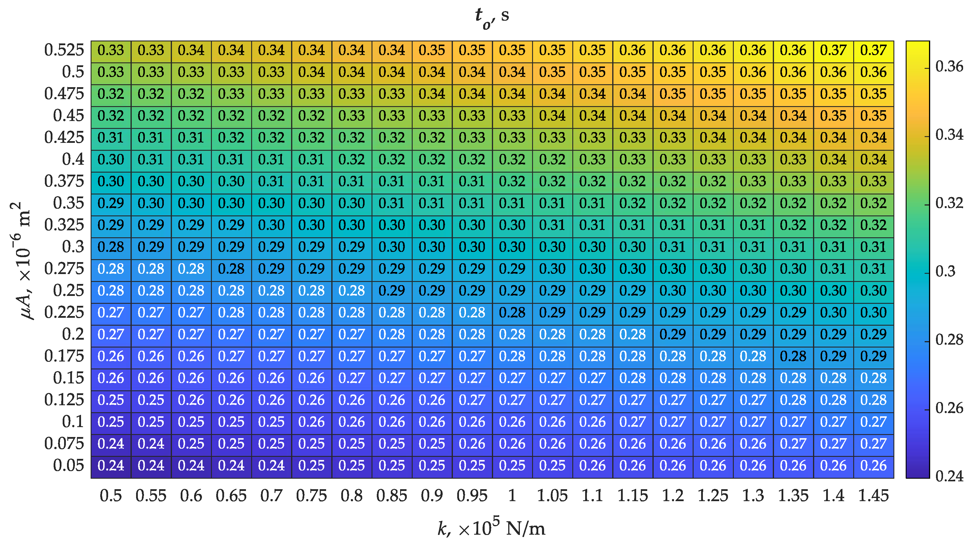
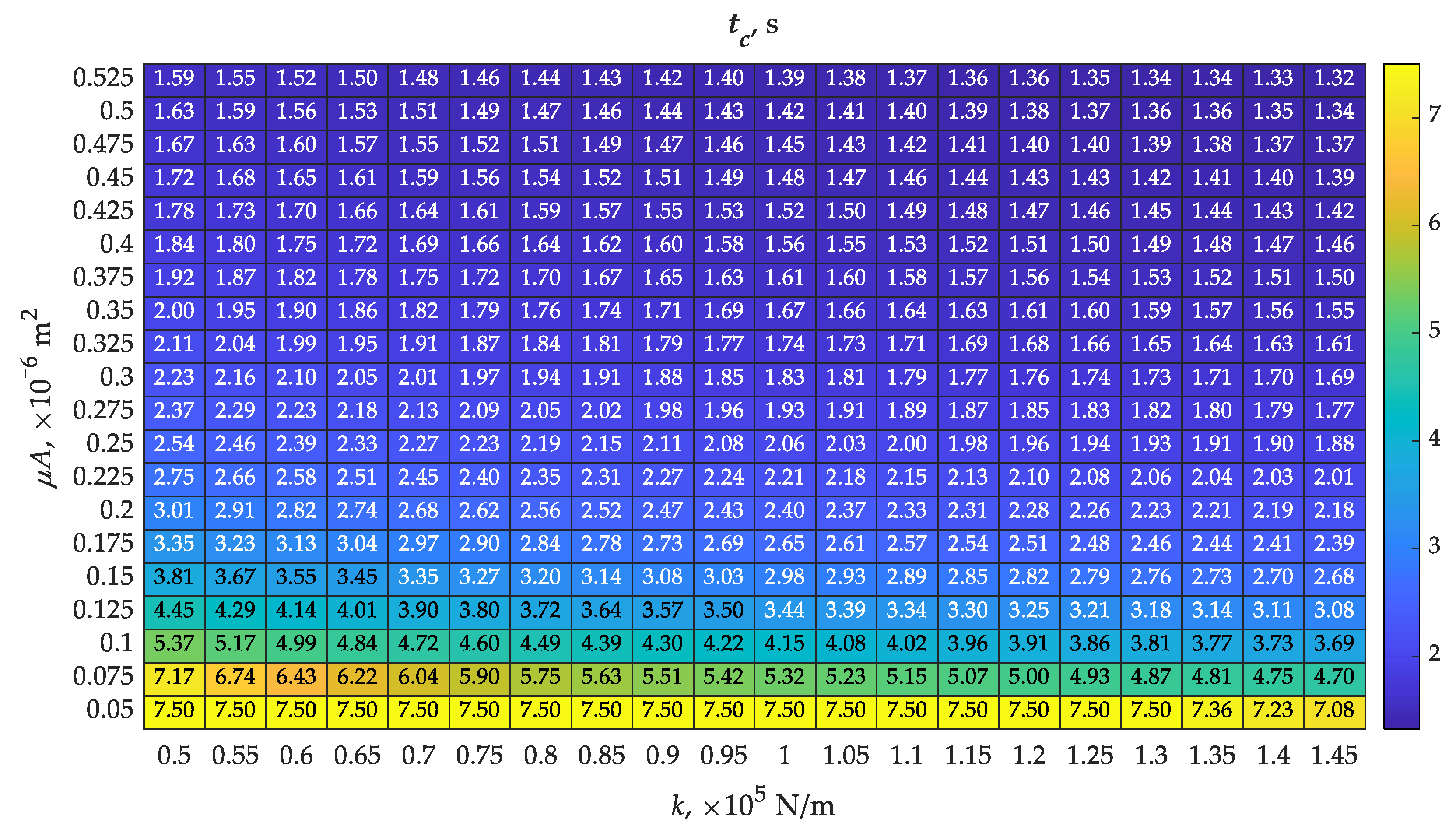
Guaranteeing a short response time (to = 0.24 s) of the valve in the differential member to the forcing was possible with a spring with the smallest stiffness of 0.5 × 10⁵ N/m and the smallest throughput value of 0.05 × 10⁻⁶ m2 among those analyzed (Figure 5). The air supply to chamber A encountered the smallest force from the spring among the analyzed cases, resulting in the fastest movement of the piston in the initial phase until hpmax was reached. The smallest value of throughput of the piston opening delayed the flow of air between chambers. This case had the opposite effect on the values of closing time, obtaining the highest value of tc = 7.50 s (Figure 6). The spring was responsible for this state of affairs, which was unable to move the piston back to its initial state, with the additional flow resistance resulting from the small throughput value of the piston bore. The extreme opposite case to that described above was found with a stiffness of 1.45 × 10⁵ N/m and a throughput of 0.525 × 10⁻⁶ m2. The opening time increased by more than 54% to 0.37 s (Figure 5), while the closing time decreased by more than 82% to 1.32 s (Figure 6). Based on this, it was concluded that the choice of spring stiffness and throughput of the opening in the piston of the differential part of the valve must be a compromise. The opening times were arranged almost symmetrically on the map (Figure 5), indicating a relationship close to proportionality. The situation was different for closing times (Figure 6), where only throughputs of less than 0.15 × 10⁻⁶ m2 resulted in a significant increase in this time. The differences in opening times to in the cases studied were just over 54%, while closing times tc were over 82%. A lack of symmetry is evident, the reason for which, in addition to the parameters in question, could also be the difference in inlet throughput (μA)in and (μA)noz. This difference affected the intensification of the air filling and compression processes in chambers A and B.
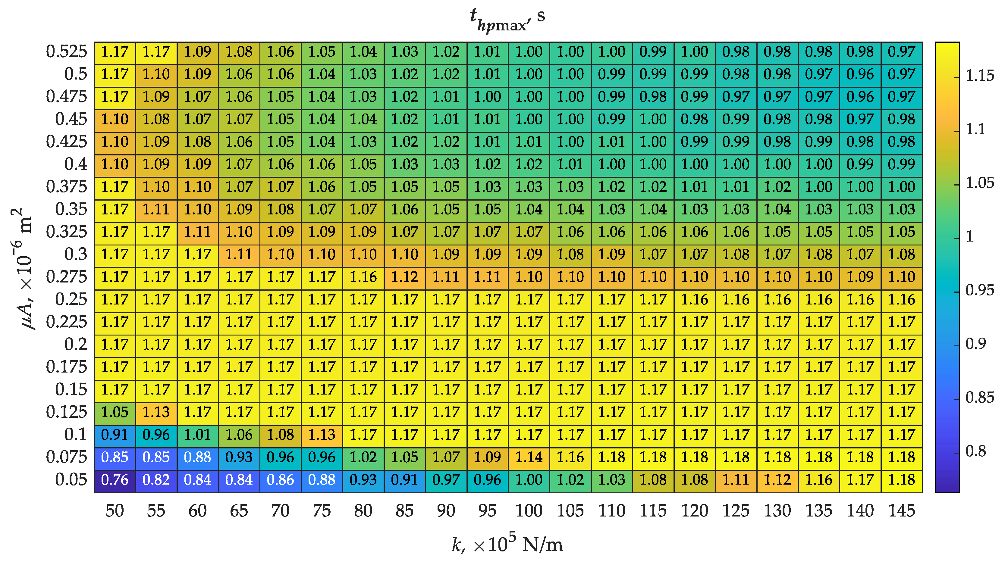
The piston did not achieve its maximum displacement in all analyzed cases (Figure 7). The part of the map with the lowest values of spring stiffness and piston bore throughput showed the achievement of the possible maximum piston displacement of 7.3 mm (Table 1), while the opposite part of the map showed only 0.97 mm. There is some correlation between the map of piston lift hpmax and the map of opening times to (Figure 5), indicating that a shorter opening time to favors the piston to achieve greater displacement, approaching hpmax. However, this is not binding, as flow is possible between chambers A and B as the piston moves, especially at higher values of piston bore throughput. Therefore, the piston may not have reached its maximum displacement. This is confirmed by a map showing the times to reach maximum piston displacement (Figure 8), where several results showed thpmax = 1.17 s. Juxtaposing this with Figure 7, one can see the different values of maximum displacements that accompany this.
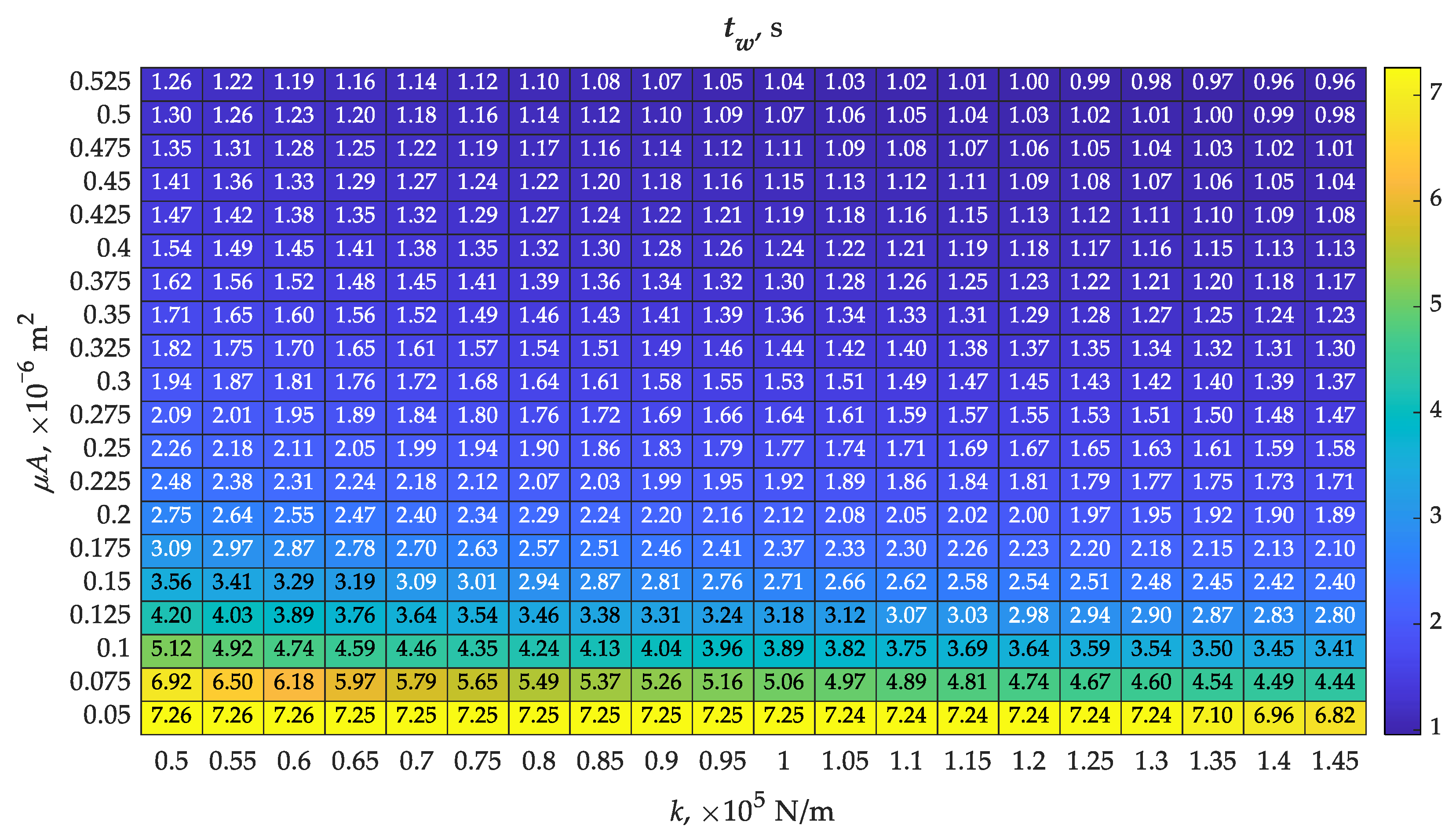
An important functional parameter of the differential part of the valve was the duration of operation in acceleration mode. This mode meant assisting the braking system with an additional reservoir located close to the trailer brake valve. The acceleration action time was determined from the relationship tw = tc to and is shown in Figure 9. The map tw was similar in distribution to the hpmax map (Figure 7). As can be seen in Figure 9, the acceleration action in the longest time dimension was possible at low throughputs, especially at 0.05 × 10⁻⁶ m2. At all adopted spring stiffness, the time exceeded 6.8 s. Obtaining the shortest acceleration action time tw was possible at a throughput of 0.525 × 10⁻⁶ m2 and a spring stiffness of 1.45 × 10⁵ N/m.

3.2. Suboptimal Functional Analysis

The selection of spring stiffness and bore throughput in the piston controlling the differential action of the trailer brake valve is a multi-faceted issue. As the maps of the individual functional parameters determined in the calculations show (Figure 5, Figure 6, Figure 7, Figure 8 and Figure 9), each of the adopted variants will be a compromise with greater or lesser side effects. The operation of the differential valve requires a different response to the forcing. Under rapid braking, this valve should switch from tracking mode to accelerating mode in the shortest possible time. Under slow braking, it should retain the feature of only tracking the driver’s intentions. Both variants of such braking are described in [45]. The question of the duration of the differential mode, beyond which the valve will switch to tracking mode, remains open. Increasing the stiffness of the spring will cause some delay in the displacement of the control piston at the beginning of the accelerating mode but will reduce the total time of its operation. The capacity of the piston bore will determine the process of abandoning the accelerating mode.
The maps obtained in the computational course and the need to determine the required parameters of the spring stiffness and the capacity of the hole in the valve control piston provided the rationale for using optimization based on the obtained maps.
Having the result maps (Figure 5, Figure 6, Figure 7, Figure 8 and Figure 9), the opening to and closing tc times were taken as inputs for optimization. On this basis, the fitness function necessary for the initialization of GA optimization was assumed in the following form:
f f i t ( x , t o , t c ) min = x t o i , j ± t c i , j
where i and j are consecutive values from the matrix of calculation results, which, in this case, are the input data.
Equation (15) takes into account the return of maximization to the level of minimization. Depending on the sign through the last term, plus or minus, it allows the determination of two optimal solutions:
  • Possibly short opening time and short closing time (opt_1);
  • Possibly short opening time and long closing time (opt_2).
The two adopted cases (opt_1 and opt_2) represent the extreme responses of the analyzed system to the input forcing. At the initial stage, the results from (Figure 5) and (Figure 6) were coded, assigning numbers 1–20. This created two 20 × 20 matrices, which were necessary for the minimization of the function ffit. In determining the size of the matrix, lower and upper constraints were also defined based on its size. The solution was sought without considering linear equations. After determining the optimal location of the solution, taking into account rounding to the nearest indices, the results were decoded, indicating the spring stiffness k and throughput (μA)noz. In addition, other parameter values, such as hpmax from Figure 7, thpmax from Figure 8, and tw from Figure 9, were determined for the optimal location. The results are shown in Table 2.
The first solution (opt_1) indicated the following parameters as optimal values: spring stiffness k = 1.45 × 10⁵ N/m and piston bore throughput (μA)noz = 0.525 × 10⁻⁶ m2 (Table 2). The corresponding opening time to obtained the largest value of 0.37 s, as the calculation was determined by the short closing time tc of 1.32 s. This resulted in a very short acceleration time of tw = 0.96 s. The effect of the set optimization condition was achieved, but with hmax = 0.97 × 10⁻³ m, it is difficult to expect the efficiency of the valve operation. The situation is completely different in the case of the second solution (opt_2: spring stiffness k = 1.30 × 10⁵ N/m and piston bore throughput (μA)noz = 0.05 × 10⁻⁶ m2). In this case, to reached a minimum value of 0.26 s and tc a maximum value of 7.5 s. As a result, the valve operates in acceleration mode tw = 7.24 s, which is almost a 30-fold increase over opt_1. The efficiency of the acceleration operation will increase significantly due to the piston reaching its maximum displacement hmax, which is 7.3 × 10⁻³ m. This guarantees the full opening of the valve. An additional optimization was still performed on three parameters, completing Equation (15) with hmax. Also in this variant, the results were consistent with those presented in Table 2. Although in [45], the differential valve was modeled in a slightly different way from the one presented in this study, the trend of changes is similar. This indicates the correctness of the adopted model and the proper control of the optimization parameters.
Summarizing the suboptimal analysis of the functional parameters of the differential part of the brake valve, it should be noted that the GA algorithm is able to accurately identify the optimal solutions in terms of the specified objective. However, only by evaluating and confronting the remaining functional quantities does the final selection of the optimal variant become possible.

4. Future Research

The calculations and analyses carried out show the effect of spring stiffness and control piston bore throughput on the performance of the differential part of the brake valve. This will result in a change in the functional characteristics of the entire braking system. The obtained maps of the distribution of indicators important in the operation of the differential part will be helpful in configuring the braking system. Further work in this area will focus on developing a system that smoothly changes the capacity of the opening connecting the two chambers below and above the control piston. Changing the spring stiffness seems too complicated at this stage. One of the options adopted is a by-pass channel connecting the two chambers of the differentiating part, in which it is planned to install an electro-valve with appropriate control. This measure is considered necessary due to the possible varying degree of load on the trailer during its operation. The variable throughput between the chambers of the differential part could ultimately relieve the operation of the brake force regulator.

5. Conclusions

Suboptimal analysis of the differential system of the pneumatic valve made it possible to evaluate its performance. Spring stiffness and piston bore throughput were used as input variables. The mathematical model, adopted on the basis of the necessary simplifications and lumped method, allowed a number of groups of results (maps) to be obtained numerically. These results served as input data for further processing aimed at selecting the most optimal solution. On this basis, it should be concluded that the work has been achieved. The main conclusions of the analysis are:
  • The smallest spring stiffness analyzed of 0.5 × 10⁵ N/m showed an opening time of 0.24 (0.33) s and a valve closing time of 7.08 (7.5) s depending on the throughput of the piston bore;
  • The highest stiffness (1.45 × 10⁵ N/m) resulted in a slight increase in opening time to 0.26 (0.37) s and a marked decrease in closing time to 1.32 (7.08) s, depending on the throughput of the piston bore;
  • The smallest piston bore throughput of 0.05 × 10⁻⁶ m2 resulted in an opening time of 0.24 (0.36) s and a closing time of 7.08 (7.5) s depending on the spring stiffness;
  • The highest piston bore throughput of 0.525 × 10⁻⁶ m2 showed a similar opening time of 0.24 (0.33) s with a significant reduction in closing time to 1.32 (1.59) s;
  • Not all analyzed configurations were able to achieve a maximum piston displacement (valve opening) of 7.3 mm, which may affect the effectiveness of the valve acceleration mode;
  • Different times of accelerating action calculated as the difference of closing and opening times did not guarantee constant efficiency due to different displacements of the piston;
  • The optimization carried out using the genetic algorithm yielded results corresponding to its stated purpose but required complementary analysis to select the optimal variant.
The results of calculations, analysis, and optimization show that the differential brake valve, although developed in the second half of the 20th century, is still a functional challenge. However, the mathematical model of the differential part of the valve presented in the paper and the proposal to use genetic optimization show the way to increase the efficiency of this type of design. The purpose of the differential valve is to accelerate the system’s operation during the first phase of sudden braking and to be able to switch to tracking operation. The suboptimal analysis included in this study indicated that this is possible.
The widespread use of electronics in actuators and their appropriate control, especially in the throughput area of the inter-chamber opening, may result in the emergence of a design of this type of valve with adaptive capabilities to trailer loading conditions.

Author Contributions

Conceptualization, M.K. and D.S.; literature review, M.K., methodology, D.S. and M.K., software, D.S. and M.K.; visualization, M.K.; resources and supervision, D.S.; original draft preparation, M.K.; writing—review and editing, D.S. All authors have read and agreed to the published version of the manuscript.

Funding

This research received no external funding.

Institutional Review Board Statement

Not applicable.

Informed Consent Statement

Not applicable.

Data Availability Statement

The datasets generated and/or analyzed during the current study are available from the corresponding author upon reasonable request.

Acknowledgments

These analyses were financed through a subsidy from the Ministry of Science and Higher Education of Poland for the discipline of mechanical engineering in the Faculty of Mechanical Engineering at Bialystok University of Technology (WZ/WM-IIM/5/2023).

Conflicts of Interest

The authors declare no conflicts of interest.

Abbreviations

ABS Anti-lock braking system
BASBrake assistance system
CFDComputational fluid dynamics
PWMPulse width modulation

References

  1. Regulation No 13 of the Economic Commission for Europe of the United Nations (UN/ECE) Uniform Provisions Concerning the Approval of Vehicles of Categories M, N and O with Regard to Braking. Available online: http://data.europa.eu/eli/reg/2016/194/oj (accessed on 5 July 2024).
  2. Jing, Z.; He, R. Electronic structural improvement and experimental verification of a tractor-semitrailer air brake system. Proc. Inst. Mech. Eng. Part D J. Automob. Eng. 2020, 234, 2154–2161. [Google Scholar] [CrossRef]
  3. Cantone, L.; Ottati, A. A simplified pneumatic model for air brake of passenger trains. Railw. Eng. Sci. 2023, 31, 145–152. [Google Scholar] [CrossRef]
  4. Krichel, S.V.; Sawodny, O. Dynamic modeling of pneumatic transmission lines in Matlab/Simulink. In Proceedings of the International Conference on Fluid Power and Mechatronics, Beijing, China, 17–20 August 2011; IEEE: Beijing, China, 2011; pp. 24–29. [Google Scholar]
  5. Kamiński, Z.; Kulikowski, K. Determination of the functional and service characteristics of the pneumatic system of an agricultural tractor with mechanical brakes using simulation methods. Eksploat. I Niezawodn. 2015, 17, 355–364. [Google Scholar] [CrossRef]
  6. Kisiel, M.; Szpica, D.; Czaban, J.; Kӧten, H. Pneumatic brake valves used in vehicle trailers—A review. Eng. Fail. Anal. 2024, 158, 107942. [Google Scholar] [CrossRef]
  7. Dindorf, R.; Takosoglu, J.; Wos, P. Review of Compressed Air Receiver Tanks for Improved Energy Efficiency of Various Pneumatic Systems. Energies 2023, 16, 4153. [Google Scholar] [CrossRef]
  8. Kulesza, Z.; Siemieniako, F.; Mikołajczyk, B. Modelowanie zaworu przekaźnikowo-sterującego. Pneumatyka 2008, 1, 31–35. [Google Scholar]
  9. Kamiński, Z. Mathematical modelling of the trailer brake control valve for simulation of the air brake system of farm tractors equipped with hydraulically actuated brakes. Eksploat. i Niezawodn. 2014, 16, 637–643. [Google Scholar]
  10. Kulesza, Z.; Siemieniako, F. Modeling the air brake system equipped with the brake and relay valves. Zesz. Nauk. 2010, 24, 5–11. [Google Scholar]
  11. Li, G.; Wei, X.; Wang, Z.; Bao, H. Study on the Pressure Regulation Method of New Automatic Pressure Regulating Valve in the Electronically Controlled Pneumatic Brake Systems in Commercial Vehicles. Sensors 2022, 22, 4599. [Google Scholar] [CrossRef] [PubMed]
  12. Kamiński, Z. Symulacyjne i Eksperymentalne Badania Pneumatycznych Układów Hamulcowych Pojazdów Rolniczych Rolniczych; Oficyna Wydawnicza Politechniki Białostockiej: Białystok, Poland, 2012. [Google Scholar]
  13. Miatluk, M.; Avtuszko, F. Dinamika Pnievmaticeskich i Gidravliceskich Privodov Avtomobilej; M. Maszinostrojenije: Moscov, Russia, 1980. [Google Scholar]
  14. Beater, P. Pneumatic Drives. System Design, Modelling and Control; Springer: Berlin/Heidelberg, Germany, 2007; ISBN 2006939785. [Google Scholar]
  15. Szpica, D. Modeling of the operation of a pneumatic differential valve increasing the efficiency of pneumatic brake actuation of road trains. In Proceedings of the Transport Means-Proceedings of the International Conference, Trakai, Lithuania, 3–5 October 2018; Volume 2018, pp. 151–156. [Google Scholar]
  16. Mystkowski, A. Zastosowanie zaworów różniczkujących w pneumatycznych układach napędowych. Pneumatyka 2004, 3, 21–23. [Google Scholar]
  17. Kamiński, Z.; Kulikowski, K. Impact of a modified braking valve for static and dynamic characteristics of pneumatic braking systems of agricultural trailers. Int. J. Heavy Veh. Syst. 2021, 28, 291–307. [Google Scholar] [CrossRef]
  18. Patil, J.N.; Palanivelu, S.; Jindal, A.K. Mathematical model of dual brake valve for dynamic characterization. In Proceedings of the SAE Technical Papers; SAE International: Pune, Maharashtra, India, 2013; Volume 5. [Google Scholar]
  19. Kumar, E.A.; Gautam, V.; Subramanian, S.C. Performance evaluation of an electro-pneumatic braking system for commercial vehicles. In Proceedings of the ICPCES 2012–2012 2nd International Conference on Power, Control and Embedded Systems, Allahabad, India, 17–19 December 2012. [Google Scholar]
  20. Topçu, E.E.; Bali, E. Modeling and analysis of an electro-pneumatic brake valve with on-off type solenoid driven by PWM technique. J. Fac. Eng. Archit. Gazi Univ. 2021, 36, 1417–1430. [Google Scholar] [CrossRef]
  21. Liu, Q.; Guo, G.; Qu, F. The Design and Simulation Analysis of Electromechanical Double Acting Pneumatic Brake Valve; Atlantis Press: Amsterdam, The Netherlands, 2016. [Google Scholar]
  22. Bao, H.; Wang, Z.; Wei, X.; Li, G. Study on the structural configurations and pressure regulation characteristics of the automatic pressure regulating valve in the electronically controlled pneumatic brake system of commercial vehicles. Appl. Sci. 2021, 11, 10603. [Google Scholar] [CrossRef]
  23. Subramanian, S.C.; Darbha, S.; Rajagopal, K.R. Modeling the pneumatic subsystem of an s-cam air brake system. J. Dyn. Syst. Meas. Control Trans. ASME 2004, 126, 36–46. [Google Scholar] [CrossRef]
  24. Yu, W.; Yang, W.; Zhao, F. Investigation of internal nozzle flow, spray and combustion characteristics fueled with diesel, gasoline and wide distillation fuel (WDF) based on a piezoelectric injector and a direct injection compression ignition engine. Appl. Therm. Eng. 2017, 114, 905–920. [Google Scholar] [CrossRef]
  25. Michalcová, V.; Kotrasová, K. The numerical diffusion effect on the cfd simulation accuracy of velocity and temperature field for the application of sustainable architecture methodology. Sustainability 2020, 12, 10173. [Google Scholar] [CrossRef]
  26. Cvetkovic, D.; Cosic, I.; Subic, A. Improved performance of the electromagnetic fuel injector solenoid actuator using a modelling approach. Int. J. Appl. Electromagn. Mech. 2008, 27, 251–273. [Google Scholar] [CrossRef]
  27. Szpica, D.; Mieczkowski, G.; Borawski, A.; Leisis, V.; Diliunas, S.; Pilkaite, T. The computational fluid dynamics (CFD) analysis of the pressure sensor used in pulse-operated low-pressure gas-phase solenoid valve measurements. Sensors 2021, 21, 8287. [Google Scholar] [CrossRef] [PubMed]
  28. Yang, Z.; Cheng, X.; Zheng, X.; Chen, H. Reynolds-Averaged Navier-Stokes Equations Describing Turbulent Flow and Heat Transfer Behavior for Supercritical Fluid. J. Therm. Sci. 2021, 30, 191–200. [Google Scholar] [CrossRef]
  29. Matyushenko, A.A.; Garbaruk, A.V. Adjustment of the k-ω SST turbulence model for prediction of airfoil characteristics near stall. J. Phys. Conf. Ser. 2016, 769, 012082. [Google Scholar] [CrossRef]
  30. Kisiel, M.; Szpica, D. Evaluating influence of CFD mesh on flow characteristics of pneumatic brake valve differential section. In Proceedings of the Engineering for Rural Development, Jelgava, Latvia, 22–24 May 2024. p. uzupelnic. [Google Scholar]
  31. Zhang, R.; Peng, J.; Li, H.; Chen, B.; Liu, W.; Huang, Z.; Wang, J. A predictive control method to improve pressure tracking precision and reduce valve switching for pneumatic brake systems. IET Control Theory Appl. 2021, 15, 1389–1403. [Google Scholar] [CrossRef]
  32. Palanivelu, S.; Patil, J.; Jindal, A.K. Modeling and Optimization of Pneumatic Brake System for Commercial Vehicles by Model Based Design Approach. In Proceedings of the SAE Technical Papers; SAE International: Orlando, FL, USA, 2017; Volume Part F130115. [Google Scholar]
  33. Korbut, M.; Szpica, D.; Panão, M.R.O. Modelling of piston pneumatic engine operation using the lumped method. Energy Convers. Manag. 2024, 306, 118310. [Google Scholar] [CrossRef]
  34. Mirjalili, S.; Mirjalili, S.M.; Lewis, A. Grey Wolf Optimizer. Adv. Eng. Softw. 2014, 69, 46–61. [Google Scholar] [CrossRef]
  35. Mirjalili, S.; Lewis, A. The Whale Optimization Algorithm. Adv. Eng. Softw. 2016, 95, 51–67. [Google Scholar] [CrossRef]
  36. Heidari, A.A.; Mirjalili, S.; Faris, H.; Aljarah, I.; Mafarja, M.; Chen, H. Harris hawks optimization: Algorithm and applications. Futur. Gener. Comput. Syst. 2019, 97, 849–872. [Google Scholar] [CrossRef]
  37. Chernov, N.N.; Palii, A.V.; Saenko, A.V.; Maevskii, A.M. A Method of Body Shape Optimization for Decreasing the Aerodynamic Drag Force in Gas Flow. Tech. Phys. Lett. 2018, 44, 328–330. [Google Scholar] [CrossRef]
  38. Gad, A.G. Particle Swarm Optimization Algorithm and Its Applications: A Systematic Review. Arch. Comput. Methods Eng. 2022, 29, 2531–2561. [Google Scholar] [CrossRef]
  39. Sohrabi, M.K.; Azgomi, H. A Survey on the Combined Use of Optimization Methods and Game Theory. Arch. Comput. Methods Eng. 2020, 27, 59–80. [Google Scholar] [CrossRef]
  40. Holland, J.H. Genetic algorithms. Sci. Am. 1992, 267, 66–72. [Google Scholar] [CrossRef]
  41. Mitchell, M. Genetic algorithms: An overview. Complexity 1995, 1, 31–39. [Google Scholar] [CrossRef]
  42. Cao, Y.J.; Wu, Q.H. Teaching genetic algorithm using MATLAB. Int. J. Electr. Eng. Educ. 1999, 36, 139–153. [Google Scholar] [CrossRef]
  43. Alinejad-Beromi, Y.; Sedighizadeh, M.; Bayat, M.R.; Khodayar, M.E. Using genetic alghoritm for Distributed generation allocation to reduce losses and improve voltage profile. In Proceedings of the Universities Power Engineering Conference, Brighton, UK, 4–6 September 2007; pp. 954–959. [Google Scholar]
  44. Maherchandani, J.K.; Agarwal, C.; Sahi, M. Estimation of Solar Cell Model Parameter by Hybrid Genetic Algorithm Using MATLAB. Int. J. Adv. Res. Comput. Eng. Technol. 2012, 1, 78–81. [Google Scholar]
  45. Szpica, D.; Kisiel, M.; Czaban, J. Simulation Evaluation of the Influence of Selected Geometric Parameters on the Operation of the Pneumatic Braking System of a Trailer with a Differential Valve. Acta Mech. Autom. 2022, 16, 233–241. [Google Scholar] [CrossRef]
Figure 1. Analyzed brake valve: (a) view of the valve; (b) and (c) proposed modifications to the valve; and (d) diagram of the valve (description in text).
Applsci 14 06792 g001
Figure 2. Forces acting in the system: (a) mechanical part; and (b) pneumatic part (description in text).
Applsci 14 06792 g002
Figure 3. Forcing and pressure waveforms at selected points of the pneumatic braking system: (a) forcing and pressure waveforms at selected points in the pneumatic system; and (b) input pressure waveforms before and after correction (description in text).
Applsci 14 06792 g003
Figure 4. Examples of the resulting waveforms from the calculations: (a) pressure waveforms in the inlet and valve chambers; (b) changes in chamber volume; and (c) piston displacement (description in text).
Applsci 14 06792 g004
Figure 5. Determined map of opening times to with varying values of spring stiffness k and throughput of the piston bore (μA)noz according to Table 1.
Applsci 14 06792 g005
Figure 6. Determined map of closing times tc with varying values of spring stiffness k and throughput of the piston bore (μA)noz according to Table 1.
Applsci 14 06792 g006
Figure 7. Determined map of maximum piston displacement hpmax with varying values of spring stiffness k and throughput of the piston bore (μA)noz according to Table 1.
Applsci 14 06792 g007
Figure 8. Determined map of times to reach the maximum piston displacement thpmax with varying values of spring stiffness k and throughput of the piston bore (μA)noz according to Table 1.
Applsci 14 06792 g008
Figure 9. Determined map of differential action times tw, with varying values of spring stiffness k and throughput of the piston bore (μA)noz according to Table 1.
Applsci 14 06792 g009
Table 1. Initial conditions, boundary conditions, and variables adopted in the analyses.
ParameterUnitValue
initial conditions
diameter of the pistonm65.5 × 10−3
diameter of the piston rodm10 × 10−3
max piston displacementm7.3 × 10−3
piston and piston rod masskg46.8 × 10−3
spring preloadN70
seal pressure force on the wallN5
static friction coefficient-0.8
kinetic friction coefficient-0.76
inlet throughputm25 × 10−6
adiabatic exponent-1.4
air constantJ/(kg·K)287.5
air temperatureK293.15
boundary conditions at t = 0 s
volume of the upper chamberm32.75 × 10−5
volume of the lower chamberm32.28 × 10−5
piston displacementm0
pressure in volumePa1 × 105
variable parameter during analysis
bore throughput in the pistonm2(0.05…0.525) × 10−6
spring stiffnessN/m(0.50…1.45) × 105
Table 2. Optimization results and values read from maps.
Parameterto, stc, shmax, ×10−3 mthmax, stw, s
range0.24…0.371.32…7.500.97…7.300.73…1.180.96…7.26
opt_1k = 1.45×10⁵ N/m; (μA)noz = 0.525 × 10⁻⁶ m2
0.371.320.990.970.96
opt_2k = 1.30×10⁵ N/m; (μA)noz = 0.05 × 10⁻⁶ m2
0.267.507.301.127.24
Disclaimer/Publisher’s Note: The statements, opinions and data contained in all publications are solely those of the individual author(s) and contributor(s) and not of MDPI and/or the editor(s). MDPI and/or the editor(s) disclaim responsibility for any injury to people or property resulting from any ideas, methods, instructions or products referred to in the content.