Article

Management Solutions and Stabilization of a Pre-Existing Concealed Goaf Underneath an Open-Pit Slope

1
School of Resources and Satety Engineering, Central South University, Changsha 410083, China
2
School of Energy Science and Engineering, Henan Polytechnic University, Jiaozuo 454003, China
*
Author to whom correspondence should be addressed.
Appl. Sci. 2024, 14(15), 6849; https://doi.org/10.3390/app14156849
Submission received: 15 July 2024 / Revised: 30 July 2024 / Accepted: 2 August 2024 / Published: 5 August 2024
(This article belongs to the Special Issue Mining Safety: Challenges and Prevention, 2nd Edition)

Abstract

:
Pre-existing concealed goafs underneath open-pit slopes (PCO-goafs) pose a serious threat to the stability of open-pit slopes (OP-slopes), which is a common problem worldwide. In this paper, the variable weight-target approaching method, equilibrium beam theory, Pratt’s arch theory, and numerical simulation are used to analyze the management solutions and stability of five PCO-goaf groups in the Nannihu molybdenum mine located in Luoyang City, Henan Province, China. The five PCO-goaf groups, numbered 1#, 2#, 3#, 4#, and 5#, are divided into four hazard classes, ranging from extremely poor to good stability. The stability of 1#, 2#, and 4# is poor and must be managed by filling, and the design strength of backfill is 1.2 MPa; caving is used to treat 3# and 5#, and the safe thickness of the overlying roof is calculated to be 10.5–41 m. After treatment, the safety coefficient of the slope is greater than 1.2, indicating that the slope is stable. This study provides insight and guidance for the safe operation of open-pit mines threatened by the existence of PCO-goafs.

1. Introduction

The safety and stability of the open-pit slope (OP-slope) is the lifeline of open-pit mining [1,2,3,4,5,6]. Underground goafs are a major factor affecting the stability of the OP-slope [7,8,9,10,11]. In recent years, open-pit landslides caused by goafs have frequently occurred. The Yanqianshan iron mine in China, Palabora mine in South Africa, and Shanxi Anjialing coal mine in China have suffered different degrees of surface collapse and landslide accidents under the influence of underground goafs and mining disturbances [12,13]. The existence of underground goafs poses a serious threat to the safe operation of open pits [14].
Considering this issue, numerous studies have examined slope stability under the influence of underground goafs. Geng et al. [15] revealed the deformation and damage law and evolution characteristics of the rocks around goafs during the transition from open-pit to underground mining through physical modeling. As a result, it was found that the fracture of the overlying strata showed a clear layer structure. Shi et al. [16] performed modeling to investigate the effects of underground mining process parameters on the deformation evolution of the OP-slope. The risk of slope destabilization gradually increased with the increase in mining volume. Li et al. [17] used physical modeling experiments to investigate the deformation and damage process and evolution of the fractured rock and found that the overburdened rock in the mining area contained a high fracture angle of 30°–90°. Owing to the size effect of the experimental model and the material properties, there is inevitably a certain error between modeling experiments and the actual open-pit mine.
Numerical simulation is an efficient and flexible research method [18,19,20,21,22], which has been used to study slope stability. Alexander Vyazmensky et al. [13] used finite element modeling/discrete element modeling to analyze the development of step-path failure caused by the collapse of large OP-slope blocks. The analysis indicated that there is a threshold or critical intact rock bridge percentage along step-path failure planes that determines the stability of an open-pit mine during caving operations. Mapurang [23] investigated the influence of pit wall stability on underground planning during the transition from open-pit to underground mining. Tan et al. [24] proposed a mining scheme for the hanging wall based on the induced caving method during the transition from open-pit to underground mining. The numerical simulation results show that a gentler inclination of the predominant joint set indicates a higher possibility of the collapsed rock mass rushing out to the bottom of the open pit. Li et al. [25] used the strength reduction method and limit equilibrium method to study the hazard classification and stability of steep slopes under different load conditions. Cao et al. [26] demonstrated that the maximum displacement occurs at the slope face at the foot of the slope and reaches 10 cm. Karakus [27] combined ABAQUS software and field monitoring and found that stress redistribution due to underground excavation is the main cause of slope damage. Rock damage is essentially the result of being subjected to loads that exceed their bearing limits [28]. Moreover, the presence of faults can change the stress distribution and increase the magnitude of changes in local stress concentrations [29]. Research shows that the slope failure process can be divided into three stages in chronological order, namely, collapse pit, small landslide, and large landslide [12].
To summarize, the current study mainly focuses on the effect of underground goafs on slope stability from open-pit to underground mines. There is fewer research on the effect of pre-existing concealed goafs underneath OP-slopes (PCO-goafs). Therefore, an open-pit mine located in Luoyang City, Henan Province, China was considered herein, and hazard grading of the goaf was performed using the variable weight-target approaching method. Equilibrium beam theory, Pratt’s arch, and other theories were utilized to design the treatment scheme for the goaf. Finally, the slope stability was analyzed using the limit equilibrium method, and the scheme was validated.

2. Engineering Background

2.1. Mine Geological Condition

The Nannihu molybdenum mine is located in Luoyang City, Henan Province, China (Figure 1). The exposed strata in the mine area are mainly composed of metamorphic rocks, classified as the Upper Luanchuan Group of the Jixianian System of the Middle Paleocene, and the strata are divided into the Baijigou Formation, the Sanchuan Formation, the Nannihu Formation, and the Coal Kiln Gully Formation, which are all in consolidated contact from the oldest to the newest. The exposed magmatic rocks are mainly variegated gabbro and porphyritic diorite to porphyritic black mica granodiorite, with a few fine-grained (porphyritic) granite veins and metamorphic volcanic rocks. The hydrogeological conditions of the mining area are simple, with no large surface water bodies and relatively good quality deep groundwater.

2.2. Mine Production Status

The strike length of the ore body is 2600 m, the thickness is generally 2–420 m, the width is 1000–1400 m, and the covering layer is thin. The minimum mining depth is designed to be set at 1105 m of elevation, the highest surface elevation is 1485 m, the sealing ring elevation is 1345 m, and the slope height is 240–380 m. The height of the open pit is 15 m, and the production capacity is 15,000 t/d. At present, the mine is about to reach the production limit, and the existence of goafs affects the production schedule of the open-pit mine.

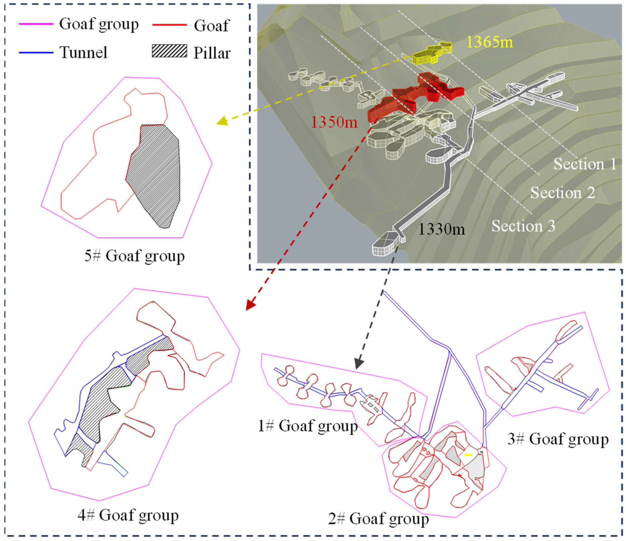
2.3. Goaf Distribution

Before open-pit mining, the underground mining method was adopted, leaving a large number of PCO-goafs untreated. The goafs are located in the northwest of the open pit, with a total area of 13,519.9 m2 and a total volume of 65,573.2 m3. According to the occurrence and the connection characteristics, the goafs are divided into five PCO-goaf groups (1#–5#). The result of the PCO-goaf division is shown in Figure 2. The groups are mainly distributed at the levels of 1330, 1350, and 1365 m. At 1365 m, there is a large independent goaf with a span of approximately 54 m. The goaf at 1330 m is concentrated. The goaf span varies from 15 to 50 m, with heights of 5–8 m.

3. Goaf Group Risk Classification
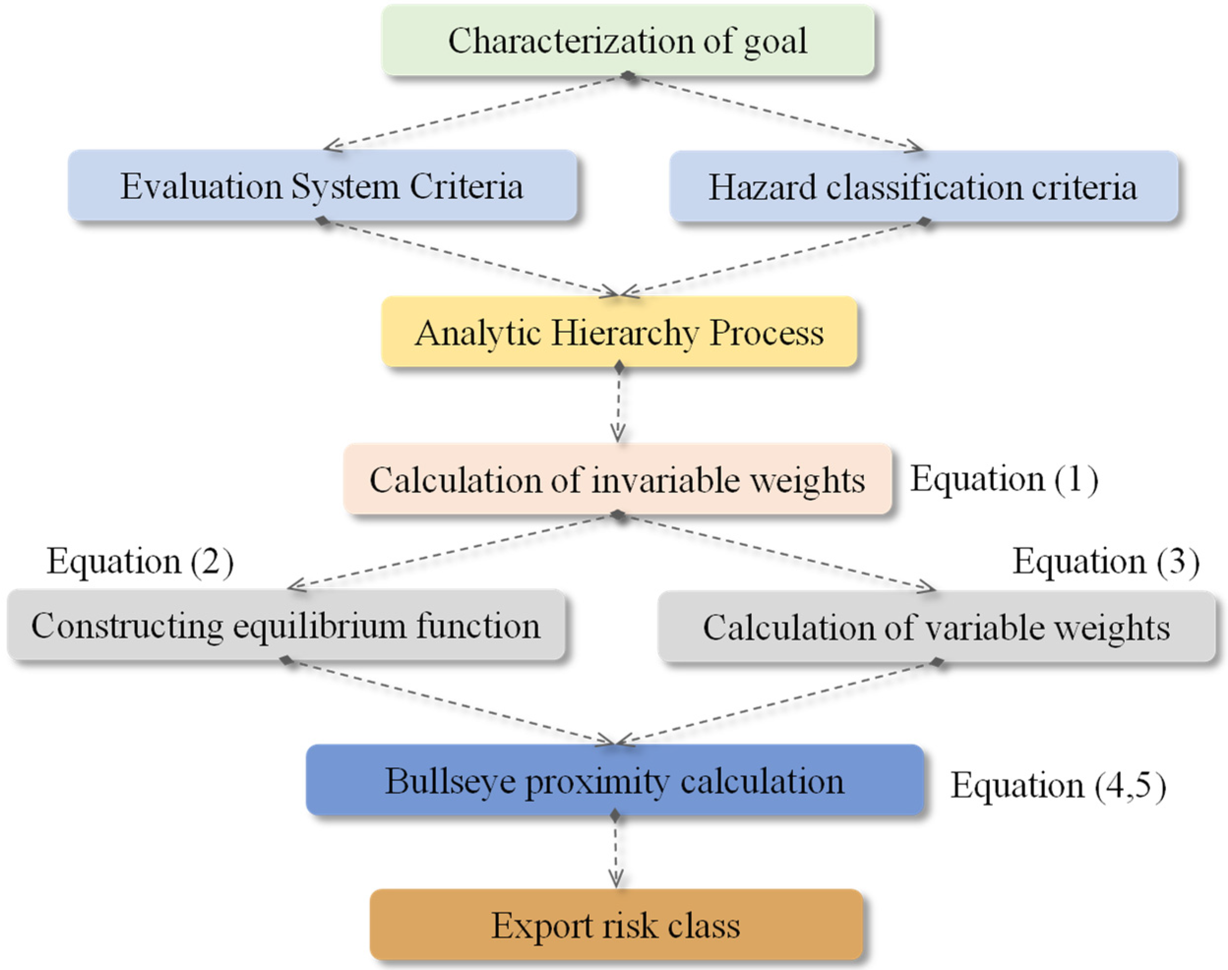
3.1. Methodology

This paper classifies the stability of PCO-goaf groups based on the comprehensive evaluation model of goaf stability with the variable weight-target approaching method. The implementation process consists of three steps. First, according to the occurrence characteristics of PCO-goafs, the index quantitative classification standard and risk classification standard are constructed. Then, the invariable weight (IW) of each index is calculated based on analytic hierarchy process. Finally, according to the assignment of the object to be evaluated, the value of the interval association function is calculated, and the bullseye coordinates are determined.
When evaluating multiple targets, the IW of the indicators is not scientific [30,31]. Therefore, the spatial factor theory is introduced based on IW, and the IW is adjusted by constructing an equilibrium function combined with the state of evaluation indicators. For example, the dangerous state indicator is encouraged to increase its weight, and the safety state indicator is punished for reducing its weight. There are n evaluation indicators, and the IW based on the analytic hierarchy process is as follows:
w 0 = w 1 0 , w 1 0 , , w n 0
For the constant a, b, c ∈ (0, 1) and a < b < c, if the uniform function Dk(X) satisfies the monotonicity of Dk(X) in the interval (0, a], [a, b], [b, c], [c, 1], and if Dk(X) is continuous when xk = a, b, c, then D(X) is a variable weight (VW) vector. VW vector C(X) can be expressed for any VW vector w0:
C ( X ) = w 1 0 D 1 ( X ) , , w n 0 D n ( X ) k = 1 n w k 0 D k ( X ) = w 0 D k ( X ) k = 1 n w k 0 D k ( X )
For the uniform function Dk(X)= Xα−1, α is the VW parameter (0 < α < 1), and α value determines the weight penalty degree; α = 1 for the IW mode, but based on the compromise, α is generally taken as 0.5. The VW formula is expressed as follows:
C ( X ) = w k 0 x k α 1 k = 1 n w k 0 x k α 1
After obtaining the VW of the evaluation index, the association function is selected to calculate the interval association function value of each index, as shown in Equation (4), and the maximum value is taken as the bullseye coordinate. Based on the value of the interval association function and the bullseye coordinates, the bullseye proximity degree is calculated, as shown in Equation (5), and then the target danger level is divided. The whole calculation process is shown in Figure 3.
Y m n l = h n l h n ( l 1 ) 2 x m n h n ( l 1 ) + h n l h n l h n ( l 1 ) h n d h n 0
U m l = 1 n = 1 r w Y m n l Y m n
Here, Ymn is the n-th evaluation indicator of the m-th object to be evaluated about the l-th grading interval correlation function value; xmn is the value assigned to each indicator of the object to be evaluated; d is the number of indicator grading; hnd, hn0 are the maximum and minimum value of the grading interval of each indicator, respectively; hnlhn(l−1) is the difference of the indicator state value falling into the grading interval where it is located.

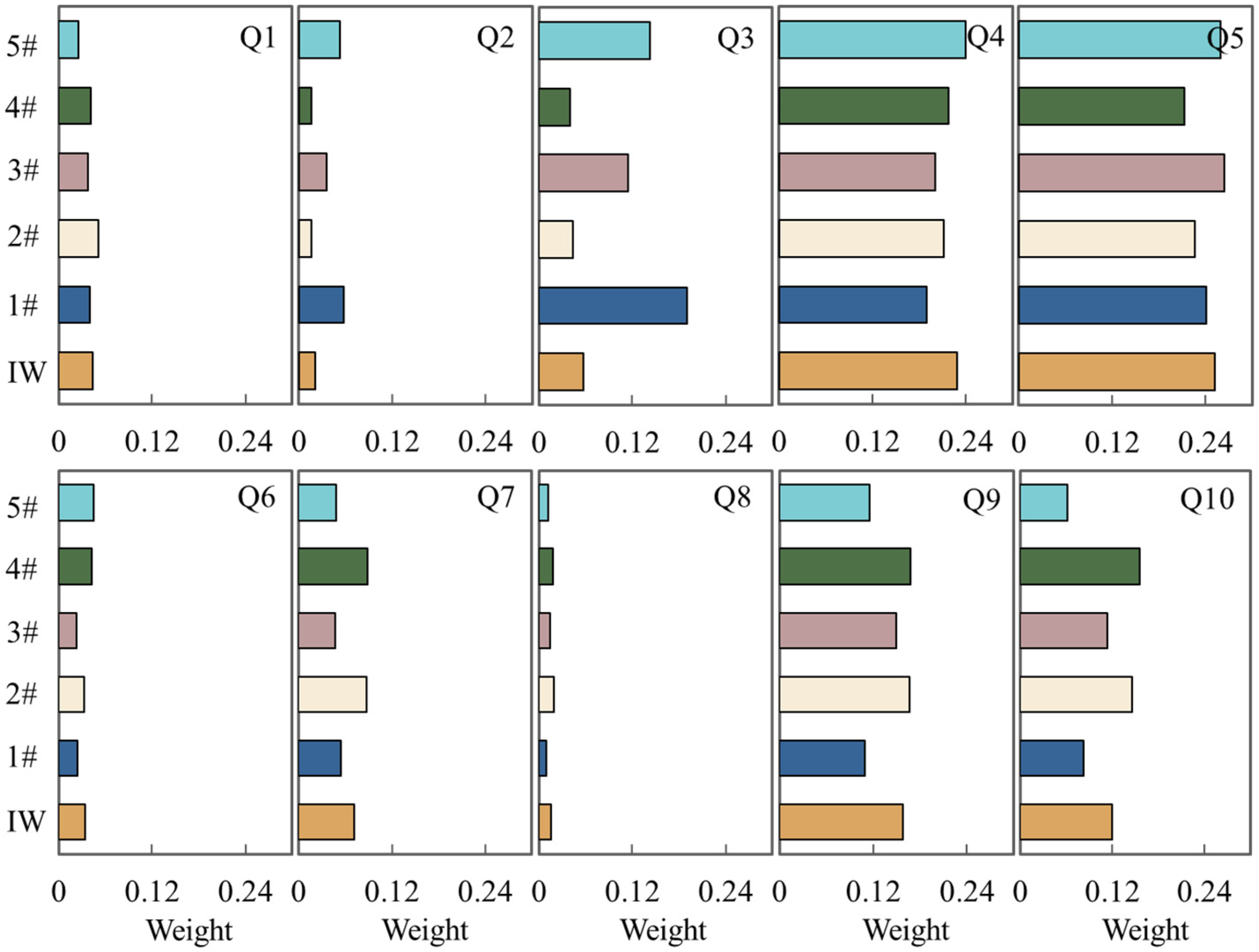
3.2. Evaluation of Quantitative Grading Standards

The construction of a comprehensive evaluation index system is the basis of the stability evaluation. There are many factors affecting the stability of a goaf. From reference to the relevant literature and mining practices, 10 evaluation indicators are selected to build a comprehensive evaluation system for the stability of PCO-goaf groups [30], as shown in Table 1. The stability of PCO-goaf groups is divided into four grades: extremely poor stability (Grade I), poor stability (Grade II), general stability (Grade III), and good stability (Grade IV). The grading standards are shown in Table 2. The non-quantifiable factors of the adjacent goaf condition and goaf shape are scored. The higher the score, the more dangerous it is.
The IWs of the PCO-goaf groups (w0 = 0.0435, 0.0212, 0.0565, 0.2288, 0.2521, 0.0336, 0.0717, 0.0158, 0.1575, and 0.1193) were calculated according to the analytic hierarchy process. The consistency test index RCR = ICI/IRI = 0.088 < 0.1 indicates matrix consistency. The weight and each indicator are substituted into Equation (3), and the VW of each evaluation index is calculated, as shown in Figure 4. There is a small difference between the VW and IW. The VW of the Q3 index fluctuates greatly. The main reason is that there are basically no pillars in the 1# and 5# PCO-goaf groups, and the index is stimulated to a large extent, resulting in a large weight increase.

3.3. Computation for Target Approaching

The equilibrium function values of each evaluation index are calculated according to Equation (5), and the bullseye coordinates are obtained by taking the maximum value. The bullseye proximity degree of goaf groups is calculated based on the bullseye coordinates, and the classification results are shown in Table 3. The bullseye proximity degrees of goaf groups 1#–5# are 0.9852, 0.9609, 0.9969, 0.9621, and 0.9609, respectively. Therefore, there is one Grade I PCO-goaf group, two Grade II PCO-goaf groups, and two Grade III PCO-goaf groups.

4. Key Parameters of the PCO-Goaf Treatment Scheme

The stability of PCO-goafs is not only the main basis for the choice of a goaf treatment scheme but also the main issue that should be considered in the design of the OP-slope. Backfill is an effective method for underground goaf management, but it inevitably increases the cost and infrastructure work [32]. The PCO-goaf groups are divided into different levels according to the variable weight-target approaching method, which is an effective means to account for both safety and economy. Referring to previous studies and mine production [33,34], Grade I and II PCO-goaf groups were backfilled [35], and Grade III and IV PCO-goaf groups were caved or blocked. The thickness of the overlying strata and the strength of the backfill are the key parameters of PCO-goaf treatment, which are discussed in detail below.

4.1. Safe Thickness of the Overlying Rock in PCO-Goafs

To ensure normal production and safe operation, the overlying strata of the open-pit mine must maintain a certain thickness when there are goafs underneath the OP-slope. Different methods are selected to calculate the safe thickness of the overlying strata [36], and the safe thickness of the PCO-goaf and roof is shown in Figure 5.
M1—Thick–span ratio method: it is based on engineering experience.
h = 0.5 K L
Here, h is the thickness of overlying strata in the goaf, m; L is the span of goaf, m; and K is the safety factor, which is 1.3.
M2—Intersection method of load transfer lines: it is based on engineering experience.
h = L 2 tan β
Here, β is the load transfer, and the diffusion angle is generally 35°.
M3—Pratt arch theory estimation method: under the action of gravity and load, the roof stress will form a natural arch, and the safe thickness of the roof should be two times that of the arch height.
h = 2 0.5 L + h K tan ( 45 θ / 2 ) f
Here, hk is the height of the goaf, m; θ is the rock internal friction angle, °; and f is the Platts coefficient of the rock.
M4—Beam theory calculation method in structural mechanics: according to the integrity of the goaf roof and surrounding rock, it can be divided into simple supported beam theory and cantilever beam theory.
h = 0.25 L γ L + ( γ L ) 2 + 8 l q σ t l σ t
Here, γ is the bulk density of the goaf roof rock, kN/m3; l is the calculated width of the roof unit, =1 m; q is the additional load of the open pit, kPa; σt is the allowable tensile stress, kPa, and uniaxial tensile strength is the allowable tensile stress.
M5—K.V. Ruppeneit theoretical calculation method: On the one hand, the theory considers the internal factors that affect the safety thickness of overlying strata in the goaf and also considers the influence of the working equipment on the upper step of the goaf.
h = K 0.25 γ L 2 / g + ( γ L / g ) 2 + 0.8 q σ B 98 σ B
σ B = σ n 3 k 3 k 0
Here, σB is the ceiling strength limit, MPa; k3 is the strength safety factor, k3 = 4–10; k0 is the structural weakening coefficient, k0 = 2–3; σn3 is the ultimate strength of rock, taken as 7–10% of the σc, MPa; and σc is the uniaxial ultimate compressive strength of the rock, MPa.
M6—Theoretical calculation method of slab beam: The theory of plate beam mainly takes into account the mechanical properties of rock and assumes that the goaf is a plate beam with fixed ends, neglecting the influence of roof span and external load.
h = K γ L 2 2 σ t
The letters in the formula are the same as above.
Due to the difference in the above six theoretical considerations, the calculated thickness of overlying strata is different to some extent. For safety, the maximum value is taken as the theoretical safe thickness. For example, the span of the 1365 m goaf is 54 m, which corresponds with 41 m for the thickness of the overlying rock.
Based on the goaf data and the layout of detection holes, the primary blast hole spacing is 6 m with a row spacing of 4 m. The pre-split hole spacing is set at 1.5 m, while the main blast hole rows are staggered in a triangular arrangement. When positioning the main blast holes above void areas, a hanging-hole method is employed with a charge depth of 0.5 m from the top of the void area and a stemming length of 5 m. Uncoupled charges are used for pre-split holes with an ultra-deep setting of 0.5 m to ensure complete roof collapse in void areas, allowing for appropriate encryption of hole spacings.

4.2. Backfill Strength

The backfill strength is the other key parameter that determines the stability of the PCO-goaf. Different from the traditional cemented paste backfill, the production process is affected by the dynamic load of trackless equipment. Therefore, the backfill strength is determined by considering the dynamic load condition of trackless equipment. The tire and the contact surface are regarded as circles with radius r, and the concentrated loads in the displacement and stress expressions are regarded as circular load distributions. The total load σz is the sum of the vertical stress σz1 and the horizontal stress σz2, whose expression is shown in Equations (13)–(15) [37]:
σ z 1 = F q z 3 r 2 + z 2 3 2 1
σ z 2 = 2 r 3 π r 2 + z 2 3 2 F τ
σ z = F q z 3 r 2 + z 2 3 2 1 2 r 3 π r 2 + z 2 3 2 F τ
where r is the radius of the circle between the tire and the contact surface, with an average of approximately 0.2 m; z is the depth of the cemented layer, m; Fq is the vertical uniform load, MPa; Fq = P/S, where P is the maximum concentrated load, taking 9 × 10⁴ N; and Fτ is the horizontal uniform load of a single tire, MPa, 0.258. The maximum vertical stress occurs at z = 0. Thus, by substituting z = 0, the design strength of the backfill is calculated to be 1.14 MPa (take 1.2 MPa).
The whole filling process is similar to cemented paste backfill. The slurry is transported to the stope through the filling pipe after passing through the mixing drum. It is worth noting that the PCO-goaf is closed so that personnel cannot enter, and the filling pipeline cannot directly carry out the stope. Therefore, it can only be filled by filling holes. In order to improve the efficiency of roof connection, the spacing of filling holes is designed to be 20~30 m. It is necessary to flush the pipeline after filling, which can prevent pipe plugging accidents.

5. Analysis of Slope Stability

The limit equilibrium method is currently one of the most prevalently employed approaches for slope stability analysis. Its essence lies in presuming that the sliding body of the slope is a rigid entity. Thus, the equilibrium state of the rigid body is examined in accordance with the limit equilibrium method in statics, and the ratio of the anti-sliding force (moment) to the sliding force (moment) is utilized as an index to evaluate the stability of the slope, namely the safety factor. The Simplified Janbu and Lowe–Karafiath methods are popular. Herein, Rocscience Slide 6.0 software was used to calculate the safety factor of the OP-slope and then the stability of the slope, after the classification treatment of the PCO-goaf was analyzed. Three section lines passing through the goaf were selected for analysis, and the position of the section line is shown in Figure 2.

5.1. Basic Parameters of the Model

Three load conditions are considered in this model: Load 1 is the self-weight condition, Load 2 is the self-weight + earthquake condition, and Load 3 is the self-weight + earthquake + blast condition. The underground water resources in the interior of the mining area are limited, the supply amount is small, and the hydrogeological investigation type is simple groundwater, which has no significant influence on the mining of the ore; thus, the seepage load condition is not considered [38]. The mechanical strength index of the slope input in the calculation process is shown in Table 4. According to the relevant regulations, namely GB 50771-2012 [39] and GB 51016-2014 [40], the safety factor of 1.20 was selected for the stability design [26].

5.2. Setting of the Blasting Vibration Conditions

According to the requirements of GB 18306-2015 [41], the peak acceleration of ground motion in the engineering area is 0.05 g, and the characteristic period of the ground motion response spectrum is 0.35 s. The corresponding basic seismic intensity value is in the VI region, and the designed basic seismic acceleration value is 0.05 g [25]. When calculating seismic stability, the coefficient of the seismic inertia force Kc should be calculated for each strip according to the following formula:
K c = α ξ β i
where α is the earthquake acceleration value; ξ is the reduction coefficient (taking 0.25); β is the dynamic distribution coefficient of block i, which is 1.5. The horizontal seismic inertia force coefficient Kc of mine design is determined to be 0.01875, and the vertical seismic inertia force coefficient is generally 65% of the horizontal coefficient, giving 0.0121875. In the case of Load 3, the influence on slope stability is considered according to a seven-degree seismic intensity (the mining area belongs to six-degree earthquake area), and the horizontal seismic coefficient is 0.025.

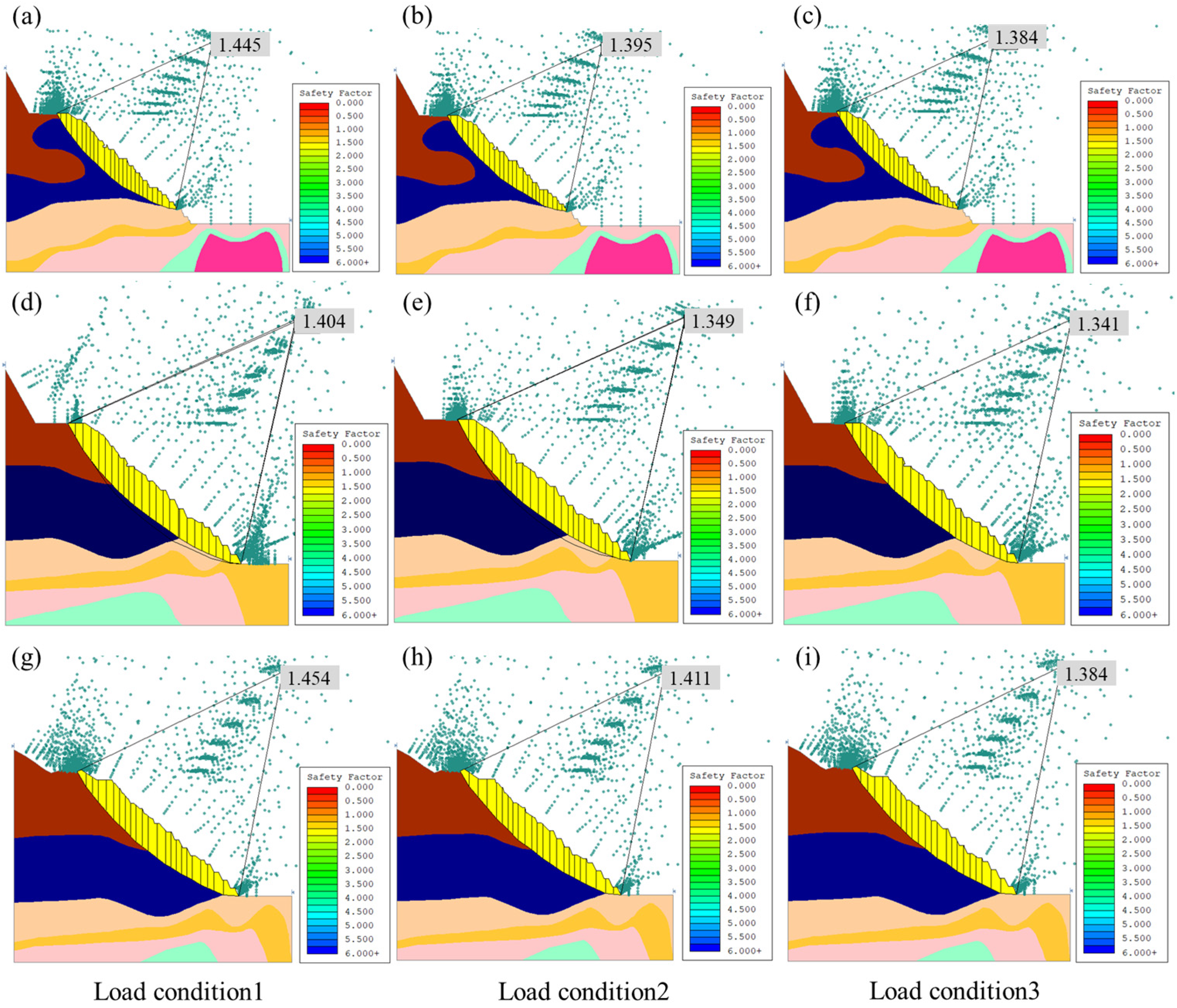
5.3. Calculation of the Safety Factor for the Slope

The numerical simulation results of slope stability are shown in Figure 6 and Figure 7, and the safety factors obtained for the slope using different calculation methods are shown in Figure 8. Regardless of which calculation method is adopted, the safety factor of the two profiles is greater than 1.2, indicating that the PCO-goaf has good stability after graded treatment. It is worth noting that under the same conditions, the slope safety factors are Load 1 > Load 2 > Load 3. For example, when Section 1 is calculated using Simplified Janbu, the safety factors are 1.314 > 1.266 > 1.248. This shows that the effect of blasting on slope stability cannot be ignored.
The stability of the OP-slope is influenced by the coupling of the goaf and blasting disturbance [42]. Blasting produces powerful stress waves, resulting in cumulative damage and stress concentration in the rock mass, and the separation and fracture of particles in the rock mass result in a stress drop, changing the stress state of the original rock [43,44]. The macroscopic manifestation involves the appearance of voids and cracks in the overlying rock mass. In addition, under the action of the roof’s gravity, the stable structure of the surrounding rock in the goaf is further changed because of the cumulative damage [45]. When the damage evolution exceeds the bearing strength of the weakened roof, local caving occurs, which generates a rock collapse zone, fracture zone, and continuous subsidence zone. The filling treatment of 2# and 3# plays a major role in slope stability. The backfill provides a reaction force that resists the goaf roof, effectively controls the underground mine, and limits the deformation of the rock mass. This paper demonstrates that the filling approach is an efficacious measure for addressing concealed goafs in open-pit mines, and its efficacy in treating underground goafs has been affirmed for a long time.
Although certain research efforts have been made in open-pit and underground collaborative mining, no systematic outcomes have emerged. Moreover, the disaster prevention measures for slopes with concealed cavities are still in their infancy [46]. Currently, the principal treatment methods of concealed goafs include filling, caving, and plugging. It is requisite to propose the corresponding management plan in accordance with the risk characteristics of the goaf. This paper offers a dependable scheme for the treatment of concealed goafs.

6. Conclusions

This paper considers an open-pit molybdenum mine as an example for designing the treatment of the OP-slope and investigating the resulting slope stability. The main conclusions are summarized as follows:
  • The slope stability is divided into four hazard classes, and the PCO-goaf groups are classified using the variable weight and bullseye approach methods. There is one Grade I PCO-goaf group, two Grade II PCO-goaf groups, and two Grade III PCO-goaf groups.
  • The balance beam theory and the Pratt arch theory are used to calculate the safety thickness of the roof over the goaf, and the safe thickness of the roof is 10.5–41 m when the goaf span is 15–50 m. The strength of the designed backfill is 1.2 MPa.
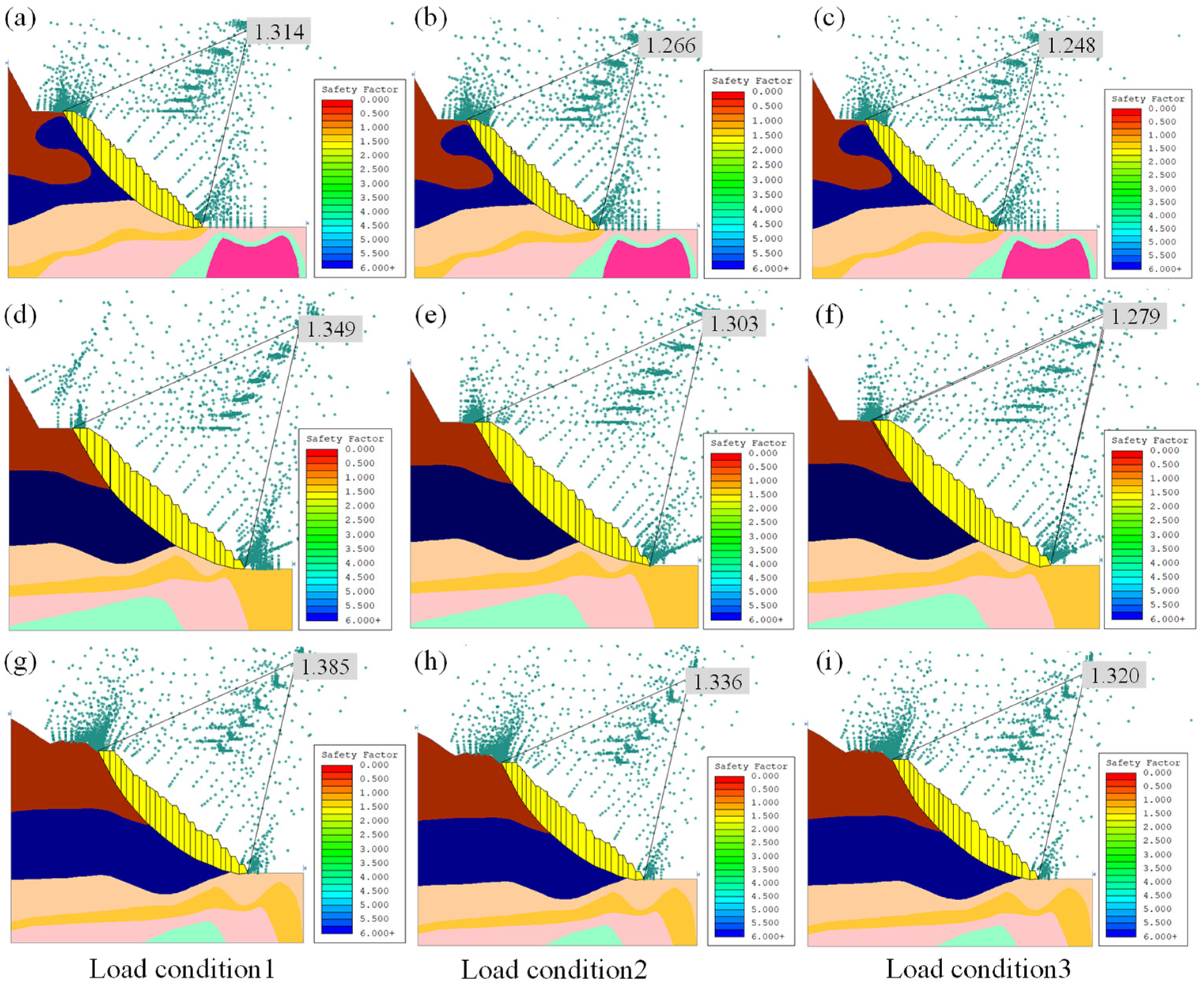
  • After the PCO-goaf groups are treated separately, Slide software was used to analyze the stability of the slope. The minimum safety factor of the PCO-goaf groups is 1.248 under the three load conditions, which is greater than the safety factor of 1.2. This shows that the goaf classification and treatment plan are reliable, and the slopes are in a stable state.
This paper proposes a scheme for jointly managing PCO-goafs using the filling and caving methods and calculates two key parameters: the strength of the backfill and the safety thickness of the roof. However, the filling and caving methods are complex processes involving many techniques and parameters, such as the backfill concentration and the spacing of filling boreholes. These parameters cannot be ignored if a comprehensive management scheme is to be formed. Due to the length limit and different focuses of this paper, all of them cannot be taken into consideration. Efforts will be made in the future to solve this problem.

Author Contributions

Conceptualization, Q.N. and Q.C.; methodology, Q.N. and Y.T. (Yunbo Tao); software, Y.T. (Yunbo Tao); validation, Q.C. and Y.T.; formal analysis, X.Z.; investigation, Q.C. and Y.T. (Yi Tan); resources, Q.N.; data curation, X.Z.; writing—original draft preparation, Q.N., Y.T. (Yunbo Tao), and Y.T. (Yi Tan); writing—review and editing, Q.C. and X.Z.; visualization, Y.T. (Yunbo Tao); supervision, Q.N. and X.Z.; project administration, Y.T. (Yunbo Tao) and X.Z.; funding acquisition, Q.C. and Y.T. (Yi Tan). All authors have read and agreed to the published version of the manuscript.

Funding

This research was funded by the 14th Five Years Key Programs for Science and Technology Development of China (No. 2021YFC2900400), the Natural Science Foundation of Hunan Province (2022JJ30714), and the Natural Science Foundation of Henan (No. 222300420045).

Institutional Review Board Statement

Not applicable.

Informed Consent Statement

Not applicable.

Data Availability Statement

The raw data supporting the conclusions of this article will be made available by the authors upon request.

Acknowledgments

The authors would like to thank Haibo Li and Jipeng Zhu for funding support in the project.

Conflicts of Interest

The authors declare no conflicts of interest.

References

  1. Azhari, A.; Ozbay, U. Investigating the effect of earthquakes on open pit mine slopes. Int. J. Rock Mech. Min. Sci. 2017, 100, 218–228. [Google Scholar] [CrossRef]
  2. Jiang, S.; Li, J.; Zhang, S.; Gu, Q.; Lu, C.; Liu, H. Landslide risk prediction by using GBRT algorithm: Application of artificial intelligence in disaster prevention of energy mining. Process Saf. Environ. Prot. 2022, 166, 384–392. [Google Scholar] [CrossRef]
  3. Lu, Y.; Jin, C.; Wang, Q.; Han, T.; Chen, L. Modeling Study on Cumulative Damage Effects and Safety Control Criterion of Open-Pit Final Slope Under Blasting. Rock Mech. Rock Eng. 2024, 57, 2081–2101. [Google Scholar] [CrossRef]
  4. Tolovkhan, B.; Demin, V.; Amanzholov, Z.; Smagulova, A.; Tanekeyeva, G.; Zairov, S.; Krukovskyi, O.; Cabana, E. Substantiating the rock mass control parameters based on the geomechanical model of the Severny Katpar deposit, Kazakhstan. Min. Miner. Depos. 2022, 16, 123–133. [Google Scholar] [CrossRef]
  5. Dick, G.J.; Eberhardt, E.; Cabrejo-Liévano, A.G.; Stead, D.; Rose, N.D. Development of an early-warning time-of-failure analysis methodology for open-pit mine slopes utilizing ground-based slope stability radar monitoring data. Can. Geotech. J. 2015, 52, 515–529. [Google Scholar] [CrossRef]
  6. Wang, Y.; Chen, Q.; Dai, B.; Wang, D. Guidance and review: Advancing mining technology for enhanced production and supply of strategic minerals in China. Green Smart Min. Eng. 2024, 1, 2–11. [Google Scholar] [CrossRef]
  7. Dintwe, T.K.M.; Sasaoka, T.; Shimada, H.; Hamanaka, A.; Moses, D.N.; Peng, M.; Meng, F.; Liu, S.; Ssebadduka, R.; Onyango, J.A. Numerical Simulation of Crown Pillar Behaviour in Transition from Open Pit to Underground Mining. Geotech. Geol. Eng. 2022, 40, 2213–2229. [Google Scholar] [CrossRef]
  8. Jiang, N.; Zhou, C.; Lu, S.; Zhang, Z. Propagation and prediction of blasting vibration on slope in an open pit during underground mining. Tunn. Undergr. Space Technol. 2017, 70, 409–421. [Google Scholar] [CrossRef]
  9. Ozdogan, M.V.; Deliormanli, A.H. Determination of possible failure surfaces in an open-pit slope caused by underground production. Boll. Di Geofis. Teor. Ed Appl. 2020, 61, 199–218. [Google Scholar] [CrossRef]
  10. Zhang, L.; Chen, Z.; Bao, M.; Nian, G.; Zhou, Z.; Zhu, T. Stability analysis and movement process determination of rock masses under open-pit to underground mining conditions. Geomech. Geophys. Geo-Energy Geo-Resour. 2022, 8, 1–19. [Google Scholar] [CrossRef]
  11. Chen, Q.; Niu, Y.; Xiao, C. Study on the influence of wet backfilling in open pit on slope stability. Sustainability 2023, 15, 12492. [Google Scholar] [CrossRef]
  12. Hu, Y.; Ren, F.; Ding, H.; Fu, Y.; Tan, B. Study on the Process and Mechanism of Slope Failure Induced by Mining under Open Pit Slope: A Case Study from Yanqianshan Iron Mine, China. Adv. Civ. Eng. 2019, 2019, 6862936. [Google Scholar] [CrossRef]
  13. Vyazmensky, A.; Stead, D.; Elmo, D.; Moss, A. Numerical Analysis of Block Caving-Induced Instability in Large Open Pit Slopes: A Finite Element/Discrete Element Approach. Rock Mech. Rock Eng. 2010, 43, 21–39. [Google Scholar] [CrossRef]
  14. Zhao, Q.; Yang, Z.; Jiang, Y.; Liu, X.; Cui, F.; Li, B. Discrete element analysis of deformation features of slope controlled by karst fissures under the mining effect: A case study of Pusa landslide, China. Geomat. Nat. Hazards Risk 2023, 14, 1–35. [Google Scholar] [CrossRef]
  15. Geng, J.; Li, Q.; Li, X.; Zhou, T.; Liu, Z.; Xie, Y. Research on the Evolution Characteristics of Rock Mass Response from Open-Pit to Underground Mining. Adv. Mater. Sci. Eng. 2021, 2021, 3200906. [Google Scholar] [CrossRef]
  16. Shi, S.; Guo, Z.; Ding, P.; Tao, Y.; Mao, H.; Jiao, Z. Failure Mechanism and Stability Control Technology of Slope during Open-Pit Combing Underground Extraction: A Case Study from Shanxi Province of China. Sustainability 2022, 14, 8939. [Google Scholar] [CrossRef]
  17. Li, X.; Li, Q.; Hu, Y.; Teng, L.; Yang, S. Evolution characteristics of mining fissures in overlying strata of stope after converting from open-pit to underground. Arab. J. Geosci. 2021, 14, 2795. [Google Scholar] [CrossRef]
  18. Lu, Y.; Jin, C.; Wang, Q.; Li, G.; Han, T. Deformation and failure characteristic of open-pit slope subjected to combined effects of mining blasting and rainfall infiltration. Eng. Geol. 2024, 331, 107437. [Google Scholar] [CrossRef]
  19. Molina, E.; Martinon, P.; Ramirez, H. Optimal control approaches for open pit planning. Optim. Eng. 2023, 24, 2887–2909. [Google Scholar] [CrossRef]
  20. Zhao, H.; Wang, D.; Ma, M.; Zheng, K. Parameter inversion and location determination of evolutionary weak layer for open-pit mine slope. Int. J. Coal Sci. Technol. 2020, 7, 714–724. [Google Scholar] [CrossRef]
  21. Samson, A.; Bowa, V.M.; Chileshe, P.R.K.; Chinyanta, S.; Manda, E. Analytical and Numerical Modelling of the Effects of Buttressing on Slide-Head Toppling Failure. Min. Metall. Explor. 2024. [Google Scholar] [CrossRef]
  22. Popescu, F.D.; Radu, S.M.; Andras, A.; Brinas, I.; Marita, M.-O.; Radu, M.A.; Brinas, C.L. Stability Assessment of the Dam of a Tailings Pond Using Computer Modeling—Case Study: Coroiești, Romania. Appl. Sci. 2024, 14, 268. [Google Scholar] [CrossRef]
  23. Mapurang, A. Influence of Pit Wall Stability on Underground Planning and Design When Transitioning from Open Pit to Sublevel Caving; University of the Witwatersrand, Faculty of Engineering and the Built Environment: Johannesburg, South Africa, 2019. [Google Scholar]
  24. Tan, B.; Ren, F.; Ning, Y.; He, R.; Zhu, Q. A New Mining Scheme for Hanging-Wall Ore-Body during the Transition from Open Pit to Underground Mining: A Numerical Study. Adv. Civ. Eng. 2018, 2018, 1465672. [Google Scholar] [CrossRef]
  25. Li, S.; Zhao, Z.; Hu, B.; Yin, T.; Chen, G.; Chen, G. Hazard Classification and Stability Analysis of High and Steep Slopes from Underground to Open-Pit Mining. Int. J. Environ. Res. Public Health 2022, 19, 11679. [Google Scholar] [CrossRef] [PubMed]
  26. Cao, H.; Ma, G.; Liu, P.; Qin, X.; Wu, C.; Lu, J. Multi-Factor Analysis on the Stability of High Slopes in Open-Pit Mines. Appl. Sci. 2023, 13, 5940. [Google Scholar] [CrossRef]
  27. Karakus, M.; Zhukovskiy, S.; Goodchild, D. Investigating the Influence of Underground Ore Productions on the Overall Stability of an Existing Open Pit. Procedia Eng. 2017, 191, 600–608. [Google Scholar] [CrossRef]
  28. Li, S.; Zhao, Z.; Hu, B.; Yin, T.; Chen, G.; Chen, G. Three-Dimensional Simulation Stability Analysis of Slopes from Underground to Open-Pit Mining. Minerals 2023, 13, 402. [Google Scholar] [CrossRef]
  29. Zhao, X.-d.; Li, L.-c.; Tang, C.-a.; Zhang, H.-x. Stability of boundary pillars in transition from open pit to underground mining. J. Cent. South Univ. 2012, 19, 3256–3265. [Google Scholar] [CrossRef]
  30. Kang, Q.; Wang, Y.; Zhang, S.; Pu, C.; Zhang, C. Prediction of Stope Stability Using Variable Weight and Unascertained Measurement Technique. Geofluids 2021, 2021, 8821168. [Google Scholar] [CrossRef]
  31. Yang, S.; Xu, Z.; Su, K. Variable Weight Matter-Element Extension Model for the Stability Classification of Slope Rock Mass. Mathematics 2021, 9, 2807. [Google Scholar] [CrossRef]
  32. Liu, Y.; Wang, Y.; Chen, Q. Using cemented paste backfill to tackle the phosphogypsum stockpile in China: A down-to-earth technology with new vitalities in pollutant retention and CO2 abatement. Int. J. Miner. Metall. Mater. 2024, 31, 1480–1499. [Google Scholar] [CrossRef]
  33. Library, U.; Daiyu, X.; Tianhong, Y.; String, W.; Jianjun, H. Analysis on disaster impact of concealed goaves underneath open-pit slope and its treatment. Chin. J. Nonferrous Met. 2020, 30, 2503–2512. [Google Scholar]
  34. Zhang, D.J.; Liu, Z.Y.; Duan, X.B.; Tuo, M.X. Research on the Mechanism of Overlying Strata Caving in Composite Goaf and its Collaborative Treatment Method. Min. Res. Dev. 2024, 44, 91–96. [Google Scholar] [CrossRef]
  35. He, K.; Swarbrick, G.; Sullivan, T. Numerical modelling of underground and open pit interaction in a gold mine. In Proceedings of the 2020 International Symposium on Slope Stability in Open Pit Mining and Civil Engineering. Australian Centre for Geomechanics, Perth, Australia, 12–14 May 2020; pp. 1031–1046. [Google Scholar] [CrossRef]
  36. Jianzhou, L. Research on Integration of Goaf Treatment and Mining in Pingshuo Dong Surface Mine. Master’s Thesis, China University of Mining and Technology, Xuzhou, China, 2015. [Google Scholar]
  37. Tao, C. Strength Design of Upward Layered Backfill under Dynamic Load of Trackless Equipment. Master’s Thesis, Kunming University of Science and Technology, Kunming, China, 2022. [Google Scholar]
  38. Guzzo Duz, B.; Moreira, C.A.; Hartwig, M.E.; Queiroz Miano, F.; Araújo, A.F. Groundwater identification using geophysical tools and its implications for the stability of slopes in an open pit mine. Geofísica Int. 2024, 63, 1033–1043. [Google Scholar] [CrossRef]
  39. GB 50771-2012; Code for Design of Nonferrous Metal Mining. Ministry of Housing and Urban-Rural Development of the People’s Republic of China, General Administration of Quality Supervision, Inspection and Quarantine of the People’s Republic of China: Beijing, China, 2012.
  40. GB 51016-2014; Technical Code for Non-Coal Open-Pit Mine Slope Engineering. Ministry of Housing and Urban-Rural Development of the People’s Republic of China, General Administration of Quality Supervision, Inspection and Quarantine of the People’s Republic of China: Beijing, China, 2014.
  41. GB 18306-2015; Seismic Ground Motion Parameters zonation Map of China. Ministry of Housing and Urban-Rural Development of the People’s Republic of China, General Administration of Quality Supervision, Standardization Administration of the People’s Republic of China: Beijing, China, 2015.
  42. Nandi, S.; Ghosh, P. Curvilinear Slope Profile–Based Seismic Stability for Rock Slopes Using Stress Characteristics Method and Generalized Hoek–Brown Criterion. J. Eng. Mech. 2024, 150, 04024049. [Google Scholar] [CrossRef]
  43. Chen, Y.; Xu, J.; Huo, X.; Wang, J. Numerical Simulation of Dynamic Damage and Stability of a Bedding Rock Slope under Blasting Load. Shock Vib. 2019, 2019, 9616859. [Google Scholar] [CrossRef]
  44. Hu, Y.; Lu, W.; Chen, M.; Yan, P.; Yang, J. Comparison of Blast-Induced Damage Between Presplit and Smooth Blasting of High Rock Slope. Rock Mech. Rock Eng. 2014, 47, 1307–1320. [Google Scholar] [CrossRef]
  45. Bo, P. Study on Instability Mechanism and Blasting Collapse Treatment of Existing Goaf in an Open-pit Mine. Ph.D. Thesis, University of Science and Technology Beijing, Beijing, China, 2022. [Google Scholar]
  46. Yuan, K.; Ma, C.; Guo, G.; Wang, P. Slope Failure of Shilu Metal Mine Transition from Open-Pit to Underground Mining under Excavation Disturbance. Appl. Sci. 2024, 14, 1055. [Google Scholar] [CrossRef]
Figure 1. Geographic location of the open-pit mine; (a) satellite map of the site; (b) PCO-goaf; (c) pithead of the goaf.
Applsci 14 06849 g001
Figure 2. Distribution characteristics of the PCO-goaf groups.
Applsci 14 06849 g002
Figure 3. Stability classification process of the PCO-goaf groups by variable weight-target approaching method.
Applsci 14 06849 g003
Figure 4. VW of the evaluation indicators.
Applsci 14 06849 g004
Figure 5. Relation between span of goaf and safety thickness of overlying rock.
Applsci 14 06849 g005
Figure 6. Simplified Janbu method used for calculating slope safety factor; Section 1: (ac); Section 2: (df); Section 3: (gi).
Applsci 14 06849 g006
Figure 7. Lowe–Karafiath method used for calculating slope safety factor; Section 1: (ac); Section 2: (df); Section 3: (gi).
Applsci 14 06849 g007
Figure 8. Safety factor of the slope under different conditions.
Applsci 14 06849 g008
Table 1. Characteristic parameters of PCO-goaf groups.
CodeEvaluation Index1#2#3#4#5#
Q1Height/m3.85.54.16.35.5
Q2Ratio of pillar width to height6.5205.616.0158.44.5
Q3Pillar area/m22511316699825
Q4Exposed area of goaf/m220633895.617402787.8724
Q5volume of goaf/m38294.321,901.2649618,908.93982
Q6Span of goaf/m335.5408.535518454
Q7Depth/m108.299.9141.974.876.5
Q8Distance from slope /m295.9181132.6144.7120
Q9Shape factor of goaf88464
Q10Status of adjacent goaf86448
Table 2. Classification standard of the goaf stability evaluation index.
Evaluation IndexGrade IGrade IIGrade IIIGrade IV
Q16~84~63~40~3
Q20.06~0.110.03~0.060.015~0.030~0.015
Q30~200200~500500~10001000~1500
Q43000~45001500~3000500~15000~500
Q515,000~25,00010,000~15,0005000~10,0000~5000
Q6250~450100~25050~1000~50
Q70~4040~8080~120120~150
Q80~7070~140140~210210~300
Q97~95~73~50~3
Q107~95~73~50~3
Table 3. Stability classification results of the PCO-goaf groups.
PCO-Goaf GroupBullseye Proximity DegreeThe Grade of PCO-Goaf Group
Grade IGrade IIGrade IIIGrade IV
1#0.98520.95300.91340.9003I
2#0.95760.96090.87010.8544II
3#0.87190.94000.99690.9454III
4#0.89150.96210.93660.8995II
5#0.94480.96020.96090.9399III
Table 4. Rock mechanical strength index of the slope.
RockDensity (kN/m3)Cohesive Force c (kPa)Internal Friction Angle φ (°)
Felsic Hornstone26.636238.41
Chalcopyrite-veinlet-bearing Biotitic Felsic Hornfels26.633838.17
Biotite diopside plagioclase28.138938.93
Skarn32.936238.97
Biotite diopside plagioclase28.138938.93
Granite25.538039.4
Disclaimer/Publisher’s Note: The statements, opinions and data contained in all publications are solely those of the individual author(s) and contributor(s) and not of MDPI and/or the editor(s). MDPI and/or the editor(s) disclaim responsibility for any injury to people or property resulting from any ideas, methods, instructions or products referred to in the content.

