Article

The Effects of Internal Curing and Shrinkage Cracking Avoidance on the Corrosion of Reinforced Concrete Walls with Superabsorbent Polymers

by
José Roberto Tenório Filho
1,2,
Nele De Belie
1 and
Didier Snoeck
3,*
1
Magnel-Vandepitte Laboratory, Department of Structural Engineering and Building Materials, Faculty of Engineering and Architecture, Ghent University, Tech Lane Ghent Science Park, Campus A, Technologiepark Zwijnaarde 60, B-9052 Ghent, Belgium
2
SIM vzw, Technologiepark Zwijnaarde 48, B-9052 Ghent, Belgium
3
Building, Architecture & Town Planning (BATir) Department, Université Libre de Bruxelles (ULB), 50 av F.D. Roosevelt, CP 194/02, B-1050 Brussels, Belgium
*
Author to whom correspondence should be addressed.
Appl. Sci. 2024, 14(16), 6901; https://doi.org/10.3390/app14166901
Submission received: 28 June 2024 / Revised: 31 July 2024 / Accepted: 4 August 2024 / Published: 7 August 2024
(This article belongs to the Special Issue Advances in Cement-Based Materials)

Abstract

:

Featured Application

Application of superabsorbent polymers in large-scale wall elements, to be used in tunnel systems or ground-retaining structures.

Abstract

The pursuit of durable and sustainable construction has driven interest in innovative materials, with superabsorbent polymers (SAPs) emerging as a promising solution, especially for the concrete industry. SAPs offer significant benefits to the durability of concrete structures, including mitigation of autogenous shrinkage, enhanced freeze–thaw resistance, crack sealing, and stimulation of autogenous healing. This study focuses on the impact of internal curing with SAPs on crack formation and corrosion initiation in large-scale reinforced concrete walls (14 m × 2.75 m × 0.8 m). Both commercial SAPs based on acrylic acid chemistry and in-house-developed SAPs based on alginates were evaluated. Key findings reveal that the reference wall exhibited visible cracking just five days after casting, while the SAP-treated wall remained crack-free throughout a 24-month monitoring period. Moreover, the reference wall showed corrosion initiation at two locations near the cracks within six months, whereas the SAP-treated wall exhibited no signs of corrosion potential. Laboratory tests further demonstrated a slight reduction in chloride penetration and carbonation in SAP-treated specimens compared to the reference. These results highlight the efficacy of SAPs in enhancing the durability and longevity of reinforced concrete structures.

1. Introduction

Superabsorbent polymers (SAPs) have emerged as a valuable solution for enhancing the durability of concrete structures, particularly in the context of internal curing, which counteracts the detrimental effects of shrinkage and leads to improved cracking behavior. These polymers, consisting of a natural and/or synthetic water-insoluble 3D network of polymeric chains crosslinked by chemical or physical bonding, possess the remarkable ability to absorb large amounts of liquids from the environment (in amounts up to 1500 times their own weight) and transform into insoluble gels [1,2]. The utilization of SAPs in cementitious materials has expanded the frontiers of construction in the past two decades, enabling the development of smart, innovative, and sustainable structures [3,4]. Previous research has demonstrated the multiple benefits of SAPs in enhancing the performance of cementitious materials beyond internal curing, as SAPs have been found to also promote crack sealing, enhance autogenous healing, control rheological properties, and increase resistance against salt-scaling under freeze–thaw conditions [5,6,7,8,9].
Internal curing has proven to be an effective strategy in reducing chloride ingress and carbonation in cementitious materials, thus enhancing the durability of concrete structures. The use of lightweight aggregates (LWAs) as internal curing agents, for example, has demonstrated significant improvements in limiting the penetration of chloride ions. Studies conducted by Bentz [10] and Zhutovsky and Kovler [11] have shown that incorporating pre-wetted fine lightweight aggregates in concrete mixtures results in reduced chloride ingress compared to reference mortar mixtures without internal curing. The authors found that the interfacial transition zone surrounding the lightweight aggregate particles exhibits lower porosity, leading to improved quality and densification of the cement paste. Similarly, Di Bella et al. [12] tested concrete mixtures internally cured with saturated LWAs and found that the migration coefficient of the internally cured concrete was slightly lower than the migration coefficient of the plain concrete (15–30% lower), which the authors attribute to increased cement hydration and reduced porosity at the interfacial zone.
When it comes to SAPs and their effects on chloride ingress, a few studies have been published on the topic. Hasholt and Jensen [13] attributed the reduction in chloride ingress caused by the internal curing of SAPs to the general densification of the paste phases as expressed by their increased gel space ratio. The authors also explained that this is different from what occurs with LWAs, where the effect of internal curing that reduces chloride transport is attributed to the improved quality of the interfacial transition zones (which does not necessarily occur with SAPs). Beyond that, they also found that adding SAPs without additional water causes an increase in the resistance of concrete to the penetration of chloride ions. In the case of SAPs added to the mixtures with additional water, the penetration of chloride ions could only be reduced if the hydration degree could be sufficiently increased.
With similar results, Ma et al. [14] concluded that the decrease in the chloride ion penetration in cementitious materials with SAPs was due to improvements in the interface transition zone between the SAP void and hardened binder matrix. Reduced chloride ingress in concrete mixtures studied by Lee et al. [15], Dang et al. [16], and Kalinowski et al. [17] was also attributed to a refinement in the pore structure and consequently limited diffusion of chloride ions caused by internal curing promoted with SAPs. In a more recent study, Van Mullem et al. [18] showed the effect of sealing and healing promoted by SAPs on the chloride ingress of cracked mortars. In the study, the authors found that the addition of SAPs improved the performance compared to a reference mixture with the same total water-to-cement ratio. Furthermore, a reference mixture with the same effective water-to-cement ratio as the SAP mixture had a comparable performance to the SAP mixture.
The objective of this study is to investigate the effects of internal curing and reduced cracking potential on the corrosion of reinforced concrete walls under realistic conditions to provide valuable insights into the performance and long-term durability of internally cured concrete structures. Although many studies have pointed out the overall positive aspects (and in some cases limitations) of the improved performance of concrete with SAPs when subjected to chloride ingress and carbonation, not much literature has been reported on large-scale structures under realistic conditions. This study is one of the first on the topic of large-scale structures.

2. Materials and Methods

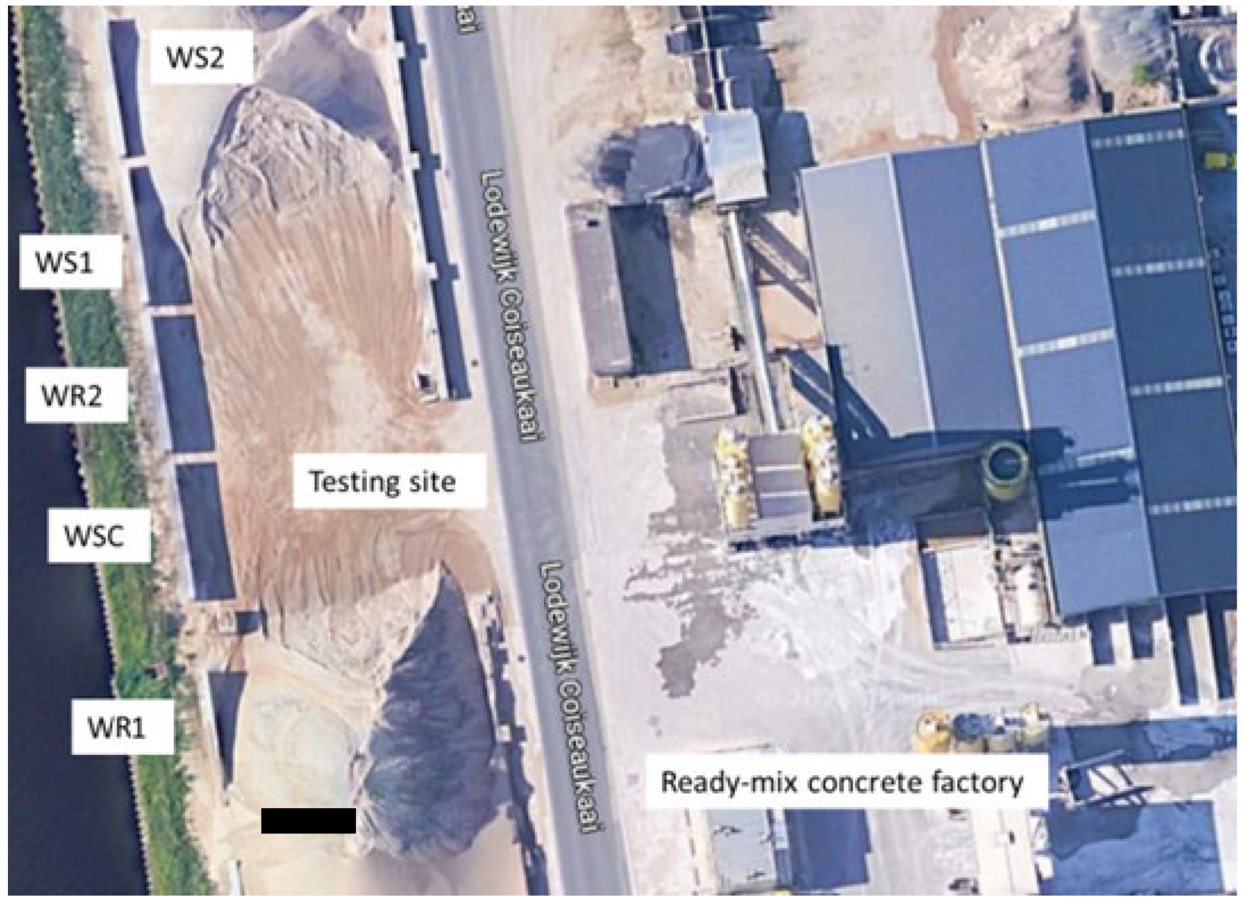
2.1. Overview of the Testing Campaign

This research focuses on the study of durability aspects, in particular corrosion initiation, carbonation, and chloride penetration, in five reinforced concrete walls with and without SAPs. The selected walls were previously investigated to examine the influence of SAPs on the mitigation of (autogenous) shrinkage and cracking of reinforced concrete walls under realistic conditions [19,20,21]. Figure 1 gives an overview of the test site.
The experimental program consisted of two parts: (1) monitoring the corrosion potential of two of the five reinforced concrete walls using integrated sensors, and (2) conducting laboratory tests on concrete specimens representing the five walls. These specimens were produced simultaneously with the pouring of the walls, using the same concrete mix.

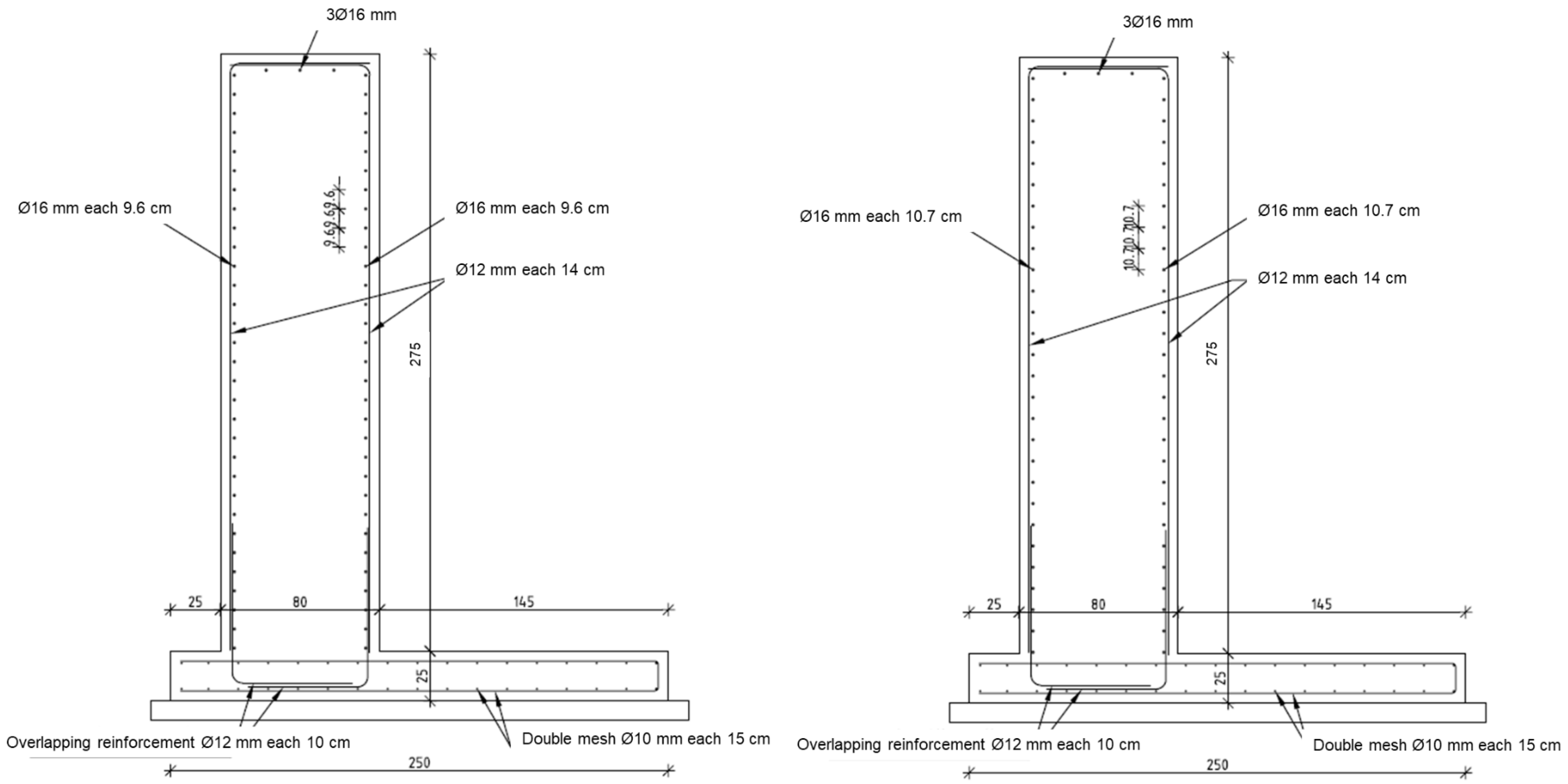
2.2. Description of the Walls and Concrete Mix Design

The walls measured 14 m × 2.75 m × 0.80 m and were cast between the last week of August 2020 and the first week of September 2020. During this period, minimum and maximum temperatures ranged from 10.9 to 19.2 °C. Removal of formwork was conducted two days after casting.
Two reference walls, WR1 and WR2, were produced without the addition of SAPs. The second reference (WR2) contained the additional water (normally to be stored in the SAPs) on top. As such, the effect of adding water could be explored without the link to internal curing. Three other walls, WS1, WS2, and WSC, were constructed with the incorporation of SAPs. WS1 used a commercial SAP (called SAP1) to mitigate autogenous shrinkage. WS2 was built with an in-house-developed SAP (SAP2) designed to promote crack sealing and partially reduce autogenous shrinkage when cracking occurs. WSC was built with a combination of SAPs SAP1 and SAP2, representing an ideal wall with the ability to mitigate autogenous shrinkage and promote self-sealing of cracks.
The concrete used for WR1 had a strength class of C35/45. It was designed to limit crack width to 0.3 mm and included 16 mm diameter reinforcement with 96 mm spacing. The other walls (WS1, WS2, and WSC) were built with concrete of strength class C30/37. Similarly, these walls were designed to limit crack widths to 0.3 mm and included 16 mm diameter reinforcement with 107 mm spacing (as shown in Figure 2). All walls were built on reinforced concrete slabs made from the same concrete used for WR1. These slabs were produced three months before the walls were constructed.
The following materials were used to make the mixtures researched in this study: (1) CEM III-B 42.5N—LH/SR from CBR, Zeebrugge, Belgium; (2) polycarboxylate superplasticizer: Tixo, 25% concentration, manufactured by BASF, Waterloo, Belgium; (3) modified polycarboxylate superplasticizer: Sika-Viscoflow 26, supplied by SIKA, Nazareth, Belgium; (4) sea sand 0/4 showing a mass absorption of 0.4%; and (5) limestone 2/20 with a mass absorption of 0.5%, next to the SAPs (please refer to the next section for details) and water. All concrete mixtures were designed with the aim of producing materials that meet consistency class S4 in terms of workability. The specific mixture designs for each wall type can be found in Table 1, listing the overall materials used next to the total and effective water-to-cement ratios.

2.3. Details about the Superabsorbent Polymers Used

SAP1, manufactured by SNF Floerger (Andrézieux-Bouthéon, France), is a crosslinked acrylate copolymer produced through bulk polymerization. It has a particle size (d50) of 360 µm and an absorption capacity of 21 g/g of mixing water when mixed with fresh concrete. Unfortunately, due to commercial confidentiality, further production details about SAP1 are not available. SAP2, produced by ChemStream bv (Edegem, Belgium), is composed solely of the monomer 2-acrylamido-2-methyl-1-propanesulfonic acid sodium salt (NaAMPS) and contains a second crosslinker that is unstable in an alkaline environment. Initially, SAP2 exhibited a reduced swelling degree, but it did not have an elevated influence on the workability and mechanical properties. However, when exposed to the alkaline environment of cementitious materials for a certain period, the crosslinks formed by the second crosslinker undergo hydrolysis. This hydrolysis process results in a significant increase in the in situ swelling potential of SAP2. SAP2 with a particle size (d50) of 100 µm showed an absorption capacity of 13 g/g of mixing water during mixing in concrete. More detailed information on this innovative SAP can be found in Reference [5].

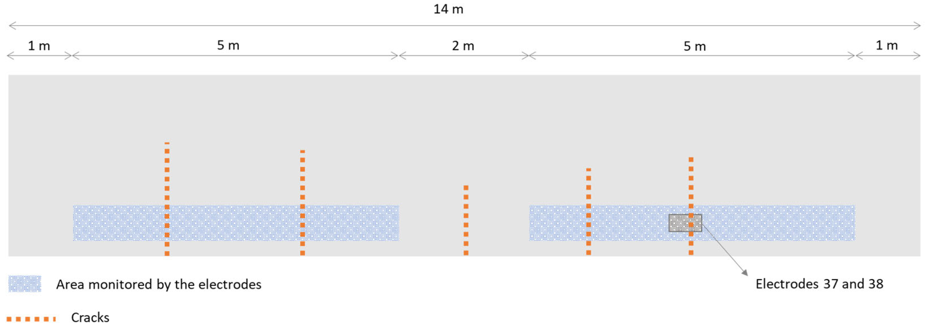
2.4. Sensors and Monitoring System Used in the Walls

The corrosion potential of reinforced concrete walls was monitored using nickel-based multi-reference electrodes (MuRe) supplied by Cescor (Milano, Italy). These electrodes were embedded in the concrete and attached to the wall reinforcement, as shown in Figure 3. The electrodes were placed 70 cm above the level of the base slab, with a spacing of 20 cm over a length of 5 m. This arrangement enabled corrosion potential to be measured at several points along the length of the walls. A total of 50 electrodes were placed in each wall, at the locations shown in Figure 4. The electrodes were calibrated and validated by the producer before installation.
A measuring unit was used to control and monitor the electrodes, each measuring 10 cm long. Installation involved connecting the electrodes to the measuring unit, which had the capacity to control up to eight electrodes simultaneously. To facilitate access for maintenance, an access box was installed in the wall housing the measurement unit. This access box had an opening to the outside, enabling the active electrodes to be changed if necessary. The Smartmote.NET system (developed by Smartmote, Stuttgart, Germany) was integrated into the measurement unit, enabling wireless, real-time monitoring. In addition, all data collected were securely stored online. Electrodes were numbered sequentially according to their location, facilitating the selection of monitored electrodes based on the location of cracks, which served as regions of interest for monitoring.

2.5. Durability Testing

The durability campaign included the following: (1) evaluation of the carbonation front in uncracked concrete specimens under accelerated conditions; (2) evaluation of the chloride penetration profile in cracked and uncracked concrete specimens (cracked specimens were used to assess the influences of immediate sealing due to SAP swelling on chloride penetration, which is a very common situation for structures near coastal areas and tunnel elements); and (3) measuring the absorption capacity of SAPs in the same sodium chloride solution as used in (2).

2.5.1. Accelerated Carbonation

From the same batches of concrete produced for wall construction, prismatic specimens (dimensions 100 mm × 100 mm × 400 mm) were prepared for accelerated carbonation tests (in analogy to the standard EN 12390-12:2020 [22]). The specimens were first cured (by wet curing) for 28 days in a controlled atmosphere room (temperature 20 ± 2 °C and relative humidity over 95%) and then moved to a lower relative humidity room (controlled atmosphere 20 ± 2 °C and 60 ± 5% RH) for 14 days. After this pre-conditioning period, the specimens were placed in a carbonation chamber, under a CO2 concentration of 1%, a temperature of 20 °C, and a relative humidity of 60%. The specimens were kept in the chamber for 19 weeks. After the exposure period, three samples measuring 100 mm × 100 mm × 50 mm were extracted from each of the large prisms (broken by splitting in a compression testing machine). One surface of each sample was sprayed with phenolphthalein (1%) to identify the depth of the carbonation front.

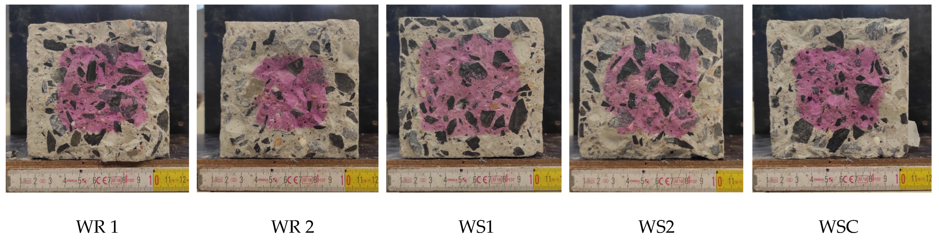
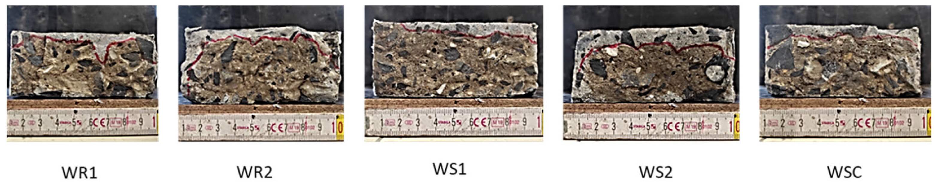
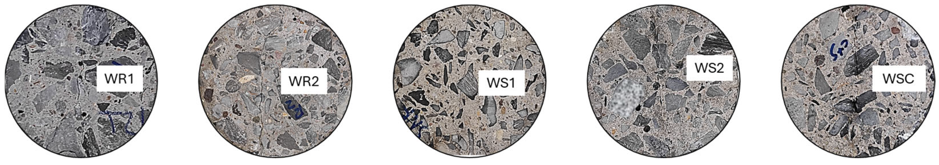
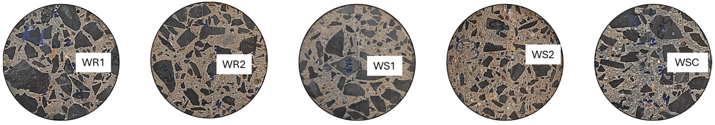
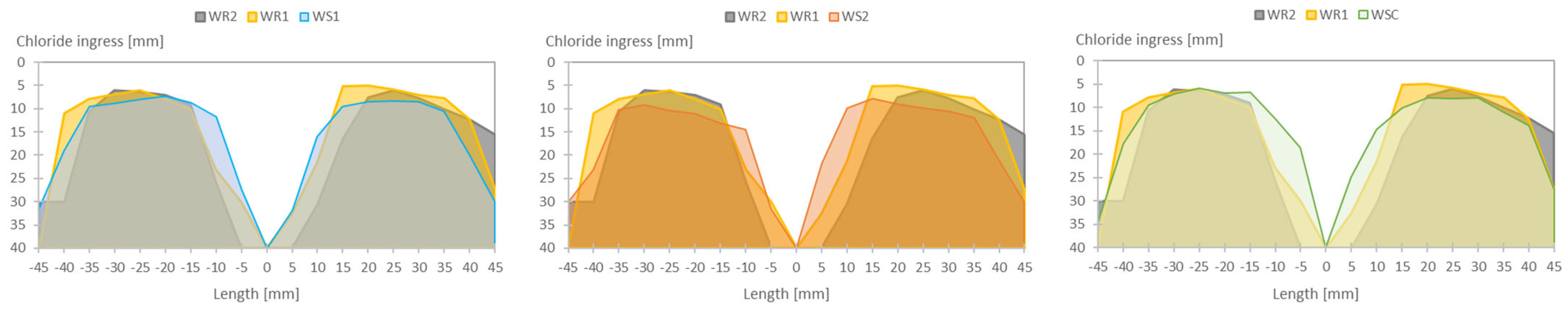
2.5.2. Chloride Penetration Profile

For chloride ingress, nine cylindrical specimens (dimensions: diameter Ø100 mm × height 50 mm) were prepared for each concrete mixture, using the same concrete as that used for the construction of the different walls. The specimens were demolded 24 h after casting and cured for 28 days in a controlled atmosphere (temperature 20 ± 2 °C and relative humidity over 95%). At 28 days, six specimens of each concrete mixture were cracked using a controlled splitting test, targeting a crack width of 250 µm. Three test conditions were studied:
  • Uncracked specimens, constantly submerged in a NaCl solution (35 g/L);
  • Cracked specimens, constantly submerged in a NaCl solution (35 g/L);
  • Cracked specimens subjected to wet/dry cycles (6 h wet/6 h dry) in a NaCl solution (35 g/L).
The selection of the different test conditions was made to simulate different exposure conditions, in addition to the realistic case of the walls. Constant submersion was chosen to simulate underwater structures, and the wet/dry cycles to simulate structures in coastal areas subjected to the variations in the tide (partly submerged and partly exposed to air).
Before being submersed in the chloride solution, the sides and bottom of the samples were coated with a double layer of epoxy resin (Episol Designtop from Resiplast, Wommelgem, Belgium) to allow the chloride to penetrate only through the top surface (unidirectionally) of the cylinders. The two coating layers were applied 24 h apart, after which the samples were placed in a closed container with the NaCl solution. After a 19-week immersion period, the samples were removed from the solution and evaluated. The chloride profile was determined using a colorimetric test with a spray of silver nitrate solution (AgNO3, 0.1 mol/L). All samples were cracked, the solution was sprayed onto the surface, and then the samples were protected from light for a period of three hours. The depth of chloride penetration was measured subsequently. For samples cracked before submersion in the sodium chloride solution, the new crack was made perpendicular to the first, so that the chloride profile could be visualized in the direction perpendicular to the original crack.

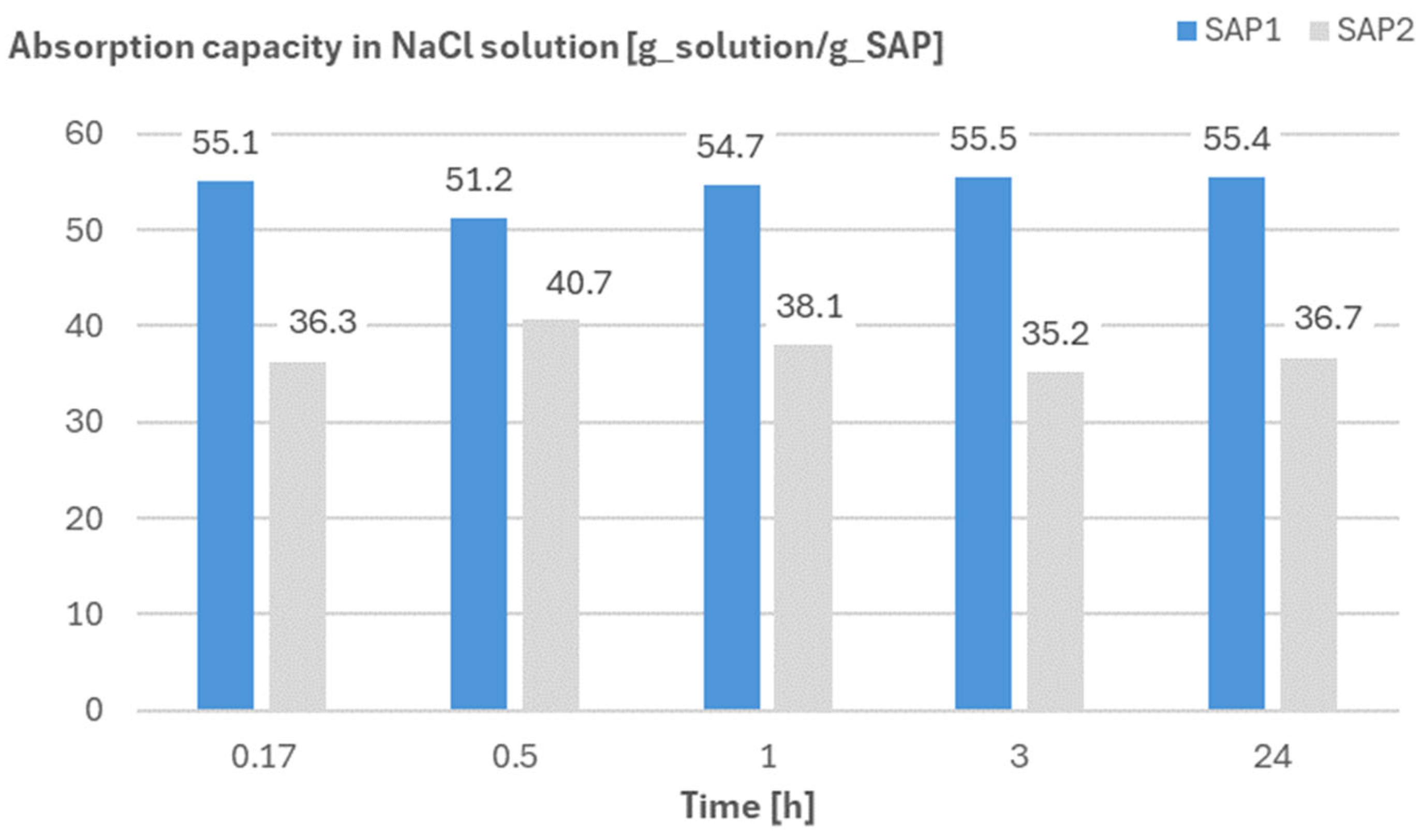
2.5.3. Absorption Capacity of SAPs in NaCl Solution by Means of the Filtration Test

The filtration test was performed as described in [23]. In this method, excess test liquid was added to dry SAP particles in a beaker, so that the particles could swell freely. The mass of dry SAP particles and the mass of added test liquid were noted. The beaker was then sealed to prevent carbonation of the testing liquid and evaporation of the liquid, and stored out of direct sunlight to avoid UV exposure. After predetermined time intervals, the mixture was filtered, and the mass of the filtered liquid was recorded. For each measurement time, a set of three beakers of “SAPs + solution” was used. The absorption capacity of the SAPs was then defined as the amount of solution [g] absorbed per gram of SAP. The same NaCl solution (with 35 g/L concentration) used in the chloride penetration test was used.

3. Results and Discussion

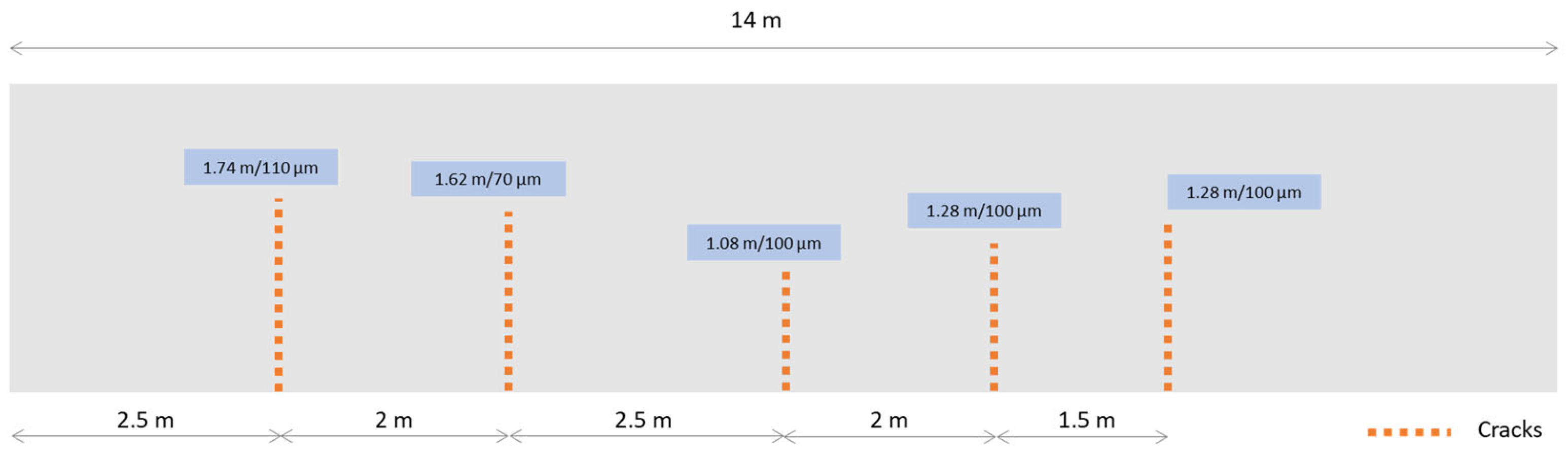
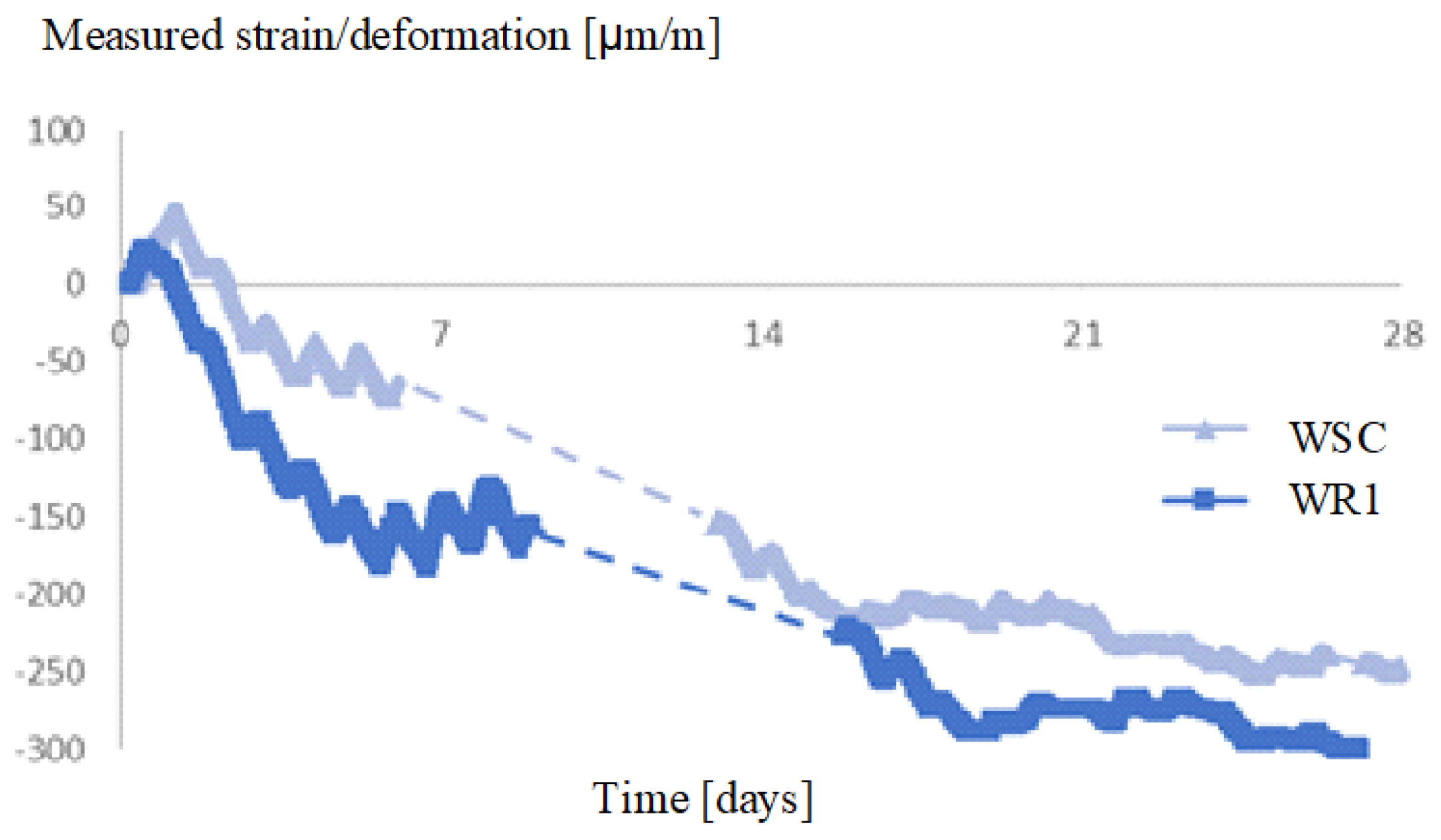
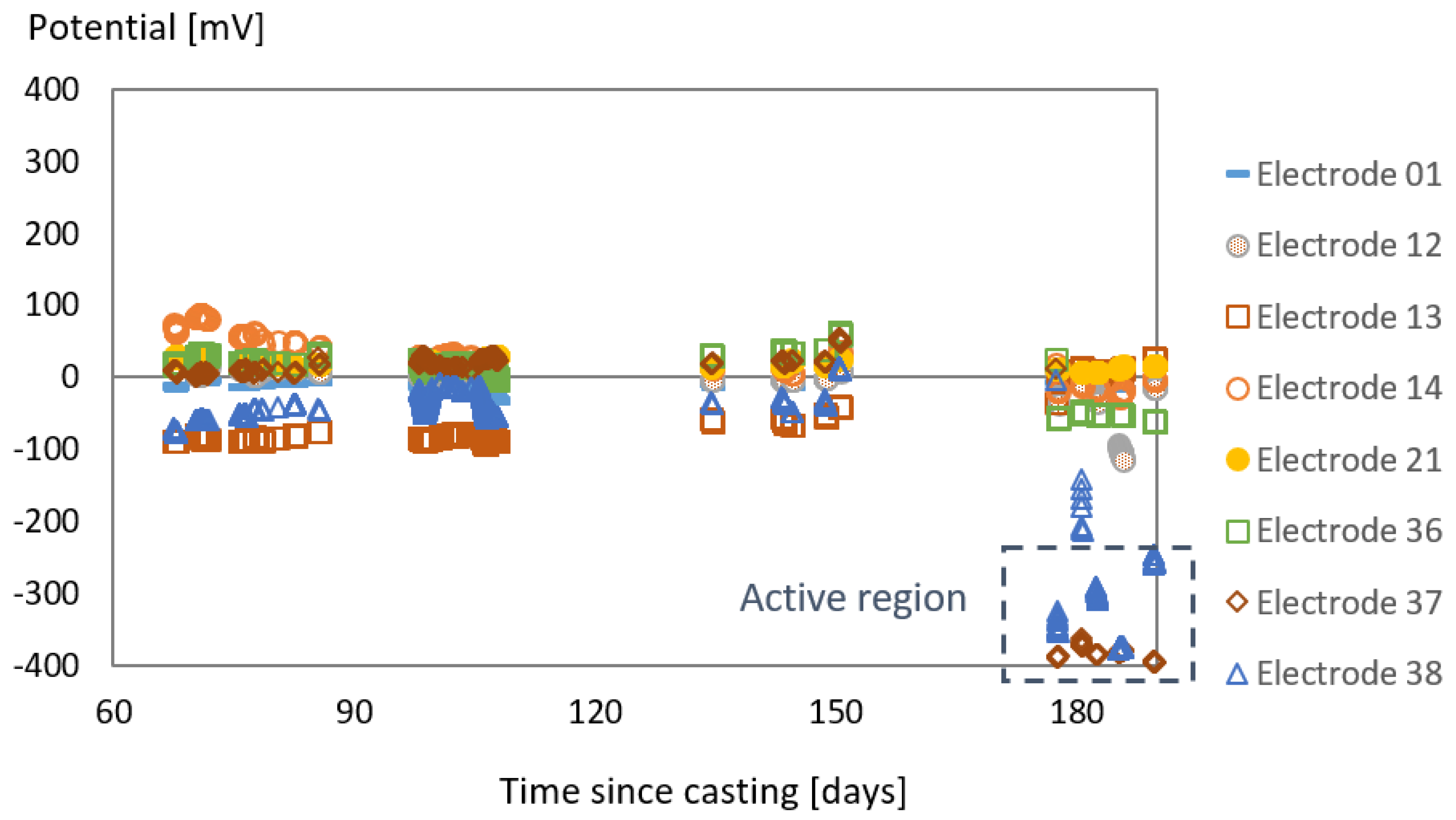
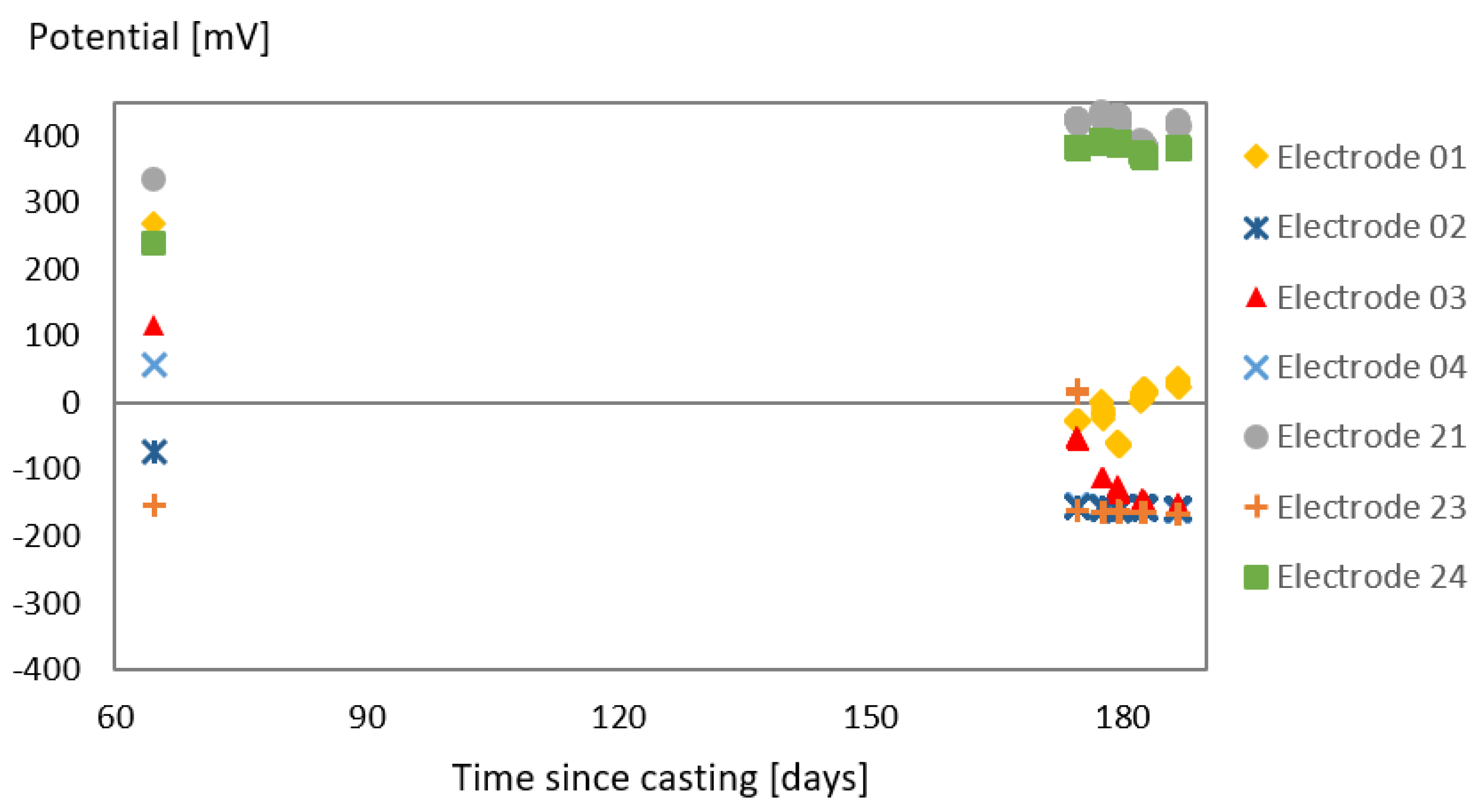
3.1. Effect of SAP Internal Curing on the Cracking and Corrosion Initiation

The first cracks were visualized on the reference walls WR1 and WR2 five and eleven days after casting, respectively. The cracking pattern in WR1 after 28 days is shown in Figure 5. For the SAP-containing walls, no cracks were noticed during the monitoring period of 24 months. Embedded optical fiber sensors were used for monitoring the shrinkage strain inside the walls. Furthermore, the ASTM C1581-04:2010 [24] test method was employed to measure the restrained shrinkage using steel rings. This test was conducted for concrete samples taken from one concrete truck from each wall.
The shrinkage levels of the walls WR1 and WSC as measured by the optical fiber sensors (see Figure 6) showcase the effects of the internal curing promoted by the SAPs, especially at early ages, as a consequence of a proper water release by the SAPs (here proper water release is defined as a controlled and continuous release of water at around the moment when self-desiccation starts to take place in the hardening matrix [25,26]).
Compared to the reference wall WR1, the SAP-containing wall WSC presented a reduction of 55% in the strain levels at 7 days. At the age of 28 days, the difference in shrinkage strain between both walls was 18%. At an early age, the tensile stresses in the surface layer may exceed the tensile strength of the material, which results in early-age cracking [27]. In this case, the effects of the internal curing promoted by SAPs are clearly observed: the strain level found in WR1 when the first cracks were detected (around −150 µm/m, 5 days after casting) is only attained in WSC 14 days after casting. The absence of cracks in the SAP walls indicates that the reduction in strain level due to internal curing during the initial stages, when the concrete is still gaining strength, functioned as a limiting factor for crack formation in the SAP walls. This demonstrates the advantage of employing SAPs for internal curing and prevention of cracking.
In terms of the time of cracking, the results from the restrained shrinkage with the steel rings (see Figure 7) also confirm the positive effects of the internal curing, as the sample prepared with concrete from WR1 presents an indication of cracking (marked as the discontinuity in the strain curve) around 15 days after casting, while the specimens prepared with concrete from WSC do not indicate any cracking potential during the whole monitoring period of 21 days. Henkensiefken et al. [28] showed that the time until cracking could be prolonged for mixtures with an increasing volume of internal curing agents. As stated by the authors, the extension in cracking time was primarily attributed to reduced shrinkage, but other factors such as a decreased elastic modulus, increased relaxation, and enhanced fracture toughness of mixtures containing internal curing agents could also contribute to the observed increase in cracking time.
In Figure 8 and Figure 9, the corrosion potential measured by some of the electrodes embedded in walls WR1 and WSC is presented. To ensure the proper functioning of the system, initially, eight electrodes located near the access box were connected to the monitoring unit. The potential measurements were conducted over a duration of approximately one month. Subsequently, two months after the walls were cast, other electrodes were monitored following the appearance of cracks.
Over a 4-month monitoring period, the measurements remained stable at all the sites monitored. However, after 6 months, a significant decrease in the potential value was observed for the sensors located near one of the cracks in the reference wall WR1 (at points 37 and 38 in particular). These observed values indicate that localized corrosion processes may have initiated or taken place, as they were in the active zone. For the WSC wall, no cracks developed visually. Unfortunately, due to a malfunction in the communication between the measurement unit inside this wall and the wireless station on site, the data set available for this wall is limited. Nevertheless, the potential values recorded by all the electrodes (above −250 mV) are outside the active zone of corrosion initiation, indicating that corrosion is not taking place.
The absence of corrosion potential in wall WSC and its early occurrence in wall WR1 can be directly correlated to the presence of cracks in the wall without SAPs. The ingress of aggressive agents in cracked concrete occurs at a significantly faster rate in comparison to uncracked concrete. In [29], Poursaee and Ross presented a comprehensive review on the role of cracks on the initiation of corrosion of reinforcement steel in concrete subjected to chloride ingress and summarized the effects of cracks on the corrosion of reinforced concrete as a function of the crack width, tortuosity, orientation, and frequency. Thus, by avoiding/delaying the formation of cracks by means of internal curing, the initiation of corrosion can also be delayed. Specifically for the case of SAPs, the internal curing will act mainly against autogenous shrinkage and not always on drying shrinkage, depending on how the SAPs are added to the mixture and if additional water is used (a detailed discussion on the topic can be found in [30,31,32]). However, cracking due to autogenous shrinkage is not neglectable. As described by Yio et al. [33], microcracks induced by autogenous shrinkage exhibit greater size, denser distribution, and interconnectedness when compared to microcracks induced by drying. These microcracks occur across the entire sample, whereas drying-induced microcracks are limited to the initial few millimeters of the exposed surface, thus representing a pressing concern in terms of the ingress of aggressive agents.

3.2. Tests with the Laboratory Specimens

In this section, the results from the laboratory tests with the specimens prepared during the casting of the walls are presented and discussed, starting with accelerated carbonation and then the chloride ingress.

3.2.1. Accelerated Carbonation

The carbonated (grey-colored) area and the area where no carbonation has taken place at the measuring time (pink-colored area) are presented in Figure 10. The visual analysis already shows that the carbonated area in WR2 is significantly larger than in all other specimens. The percentage of the carbonated area in all SAP-containing mixtures is placed between WR1 and WR2 (68%, 75%, 55%, 61%, and 66% for WR1, WR2, WS1, WS2, and WSC, respectively).
The depth of the carbonation front was measured in at least three different points of each of the four surfaces of the specimen. The average values for each mixture were taken considering all measurements in the four surfaces of the three specimens evaluated per batch. The results are presented in Figure 11. The SAP-containing mixtures performed similarly or slightly better than WR1, in contrast, WR2 presented the deepest carbonation front. Again, the smaller carbonation depth found for the mixtures with SAP1 and SAP2 could be related to a densification of the matrix caused by internal curing, and it is more pronounced for SAP1 than SAP2.
Despite the fact that the inclusion of SAPs with additional water might increase the macro porosity of the mixture in comparison to a reference where no SAPs were added [34,35], this might not be the only parameter influencing the progress of the carbonation front in the mixtures. The smaller carbonated area found in the specimens with SAPs can be an indication that the SAPs are actually causing densification of the cementitious matrix near the SAP void due to the effects of internal curing and further hydration [36]. This effect is more pronounced in SAP1 and can be linked to the more efficient water release and internal curing observed in this SAP in comparison to SAP2 in other studies [37]. Another explanation for the less severe carbonation in the SAP specimens could be that a higher internal humidity of the specimens (caused by the SAPs) would delay the carbonation. However, before entering the carbonation chamber, all specimens were pre-conditioned under a controlled atmosphere of 20 ± 2 °C and 60 ± 5% RH for 14 days. This curing condition enables the occurrence of drying, which is more intense for the SAP-containing mixtures, as already observed during the drying shrinkage tests under the same environmental conditions (as described in [19]), ensuring that by the time the specimens enter into the carbonation chamber, their internal humidity level is comparable (regardless of the presence of SAPs). Thus, the hypothesis of matrix densification and improved internal curing seems more plausible.

3.2.2. Uncracked Specimens Constantly Submerged in a Solution of NaCl (35 g/L)

In Figure 12, the chloride-affected areas of the tested specimens from each mixture are shown. Initially, it can be observed that a smaller affected area was found in the mixtures containing SAPs in comparison to WR2 and slightly smaller when compared to WR1, especially in the specimen containing only SAP1.
The resulting profiles are shown in Figure 13. In a general overview, the ingress of chlorides in the middle part is similar for all mixtures, which provides evidence that the inclusion of SAPs with extra water did not increase the permeability of the mixtures, which would have a negative effect in this case by increasing the chloride ingress. Additionally, by considering the total length of the tested surface, it becomes clear that, indeed, the mixtures containing SAP1 were less affected by the chloride ingress, especially compared to WR2. Analysis of the relative affected areas also provided the following values: 21.2%, 28.9%, 18.7%, 27.2%, and 19.9% for WR1, WR2, WS1, WS2, and WSC, respectively.
It can also be observed that in the first 20 mm on one or both sides of the specimens, a deeper chloride penetration was identified. There are two possibilities that could explain this result: (1) failure in the coating of the specimens, or (2) the wall effect during the casting of the specimens. Given that all specimens were coated using the same material and procedure, and that they did not present the same penetration depth (WR2 for instance has a deeper chloride penetration on the edges in comparison to the other mixtures), the second theory seems to be more plausible, but a combination of both effects to some extent should not be discarded. In fact, the wall effect during casting causes a concentration of cement paste at the contact surface with the molds. The cement paste is the most porous phase of the concrete, thus it is more susceptible to chloride penetration. As was already observed for the specimens evaluated for carbonation, in the mixtures containing SAP1, a densification of the cement matrix due to internal curing and further hydration could also be responsible for the lower chloride ingress when compared to both references. In addition, a second hypothesis considering the binding of chloride ions by the SAPs should not be discarded. It is widely known that upon contact with ionic solutions, there is an ion exchange between the SAP particles and the solution, which in most cases results in the entrapping of ions by the SAPs, for example, calcium ions present in the cement pore solution. Regarding salts, a similar effect has been reported in [38,39], where the authors state that hydrophilic groups inside the polymer structure can bind salt ions easily in a mechanism quite similar to the complexation observed with the calcium ions in the cement pore solution.

3.2.3. Cracked Specimens Constantly Submerged and Subjected to wet/dry Cycles in a NaCl Solution

The visual aspects of the cracked surface of the specimens under continuous immersion and wet/dry cycles are depicted in Figure 14 and Figure 15. At first look, the specimens subjected to continuous immersion presented no filling of the cracks after the immersion period. In contrast, the specimens subjected to wet/dry cycles presented a slight filling of the surface of the crack, which can be related to salt crystallization during the wet/dry cycles.
The chloride ingress profiles of the cracked specimens (subjected to continuous immersion and wet/dry cycles) are presented in Figure 16 and Figure 17. The figures are divided into parts (a), (b), and (c) to facilitate the comparison of each SAP mixture with the two reference mixtures. The zero value in the y-axis represents the top surface of the specimens (from where the chlorides penetrate) and the zero value in the x-axis represents the location of the crack.
For the first group, few significant differences were observed when comparing the specimens. Still, the SAP-containing mixtures did not perform worse than the reference mixtures, which again confirms that the inclusion of air voids expected with the addition of SAPs did not necessarily increase the permeability of the matrix, which is a positive outcome. Furthermore, the ingress of chloride solution in the specimen might be delayed by the presence of the SAP in possibly two different ways: (1) if the SAP voids are empty, the dry SAP particle inside the void will have the ability to re-swell upon absorption of the chloride solution; (2) if the SAP void contains a (fully or partially) swollen SAP particle, then it is likely that transport will be slower than in pure liquid given the higher viscosity of the liquid entrapped in the SAP. This has already been hypothesized by Bentz et al. in [40] by comparing the transport properties in a swollen SAP with that of a liquid to which a viscosity modifying agent has been added. Apart from that, there is once again an indication of a slight densification of the matrix when SAP1 was used. In terms of relative values for the affected area (meaning the area where chlorides were found in relation to the total area of the specimen), the following values were found: 41.2%, 41.8%, 39.2%, 39.7%, and 38.5% for WR1, WR2, WS1, WS2, and WSC, respectively.
For the second group, in terms of relative area affected by the chloride ingress, the following values were found: 38%, 42%, 36%, 37%, and 35% for WR1, WR2, WS1, WS2, and WSC, respectively. In that sense, all SAP-containing mixtures performed better than the reference with the same effective water-to-cement ratio and better than the second reference with the same total water-to-cement ratio. Additionally, although no healing or permanent sealing of the cracks was obtained, there is a visible reduction in the chloride penetration perpendicular to the crack, which could in fact also be related to the partial filling of the crack surface due to salt crystallization (as indicated in Figure 15).
Overall, although the internal curing reduced the risk of corrosion for the SAP wall (mostly due to the reduction in the shrinkage cracking potential), and the presence of SAPs could reduce the chloride ingress and the progress of carbonation in the concrete mixtures studied here, it is important to highlight that these results are specific for the concrete mixtures presented in this study. After all, the performance of cementitious materials with SAPs is highly dependent on the total water-to-cement ratio of the mixture [1].

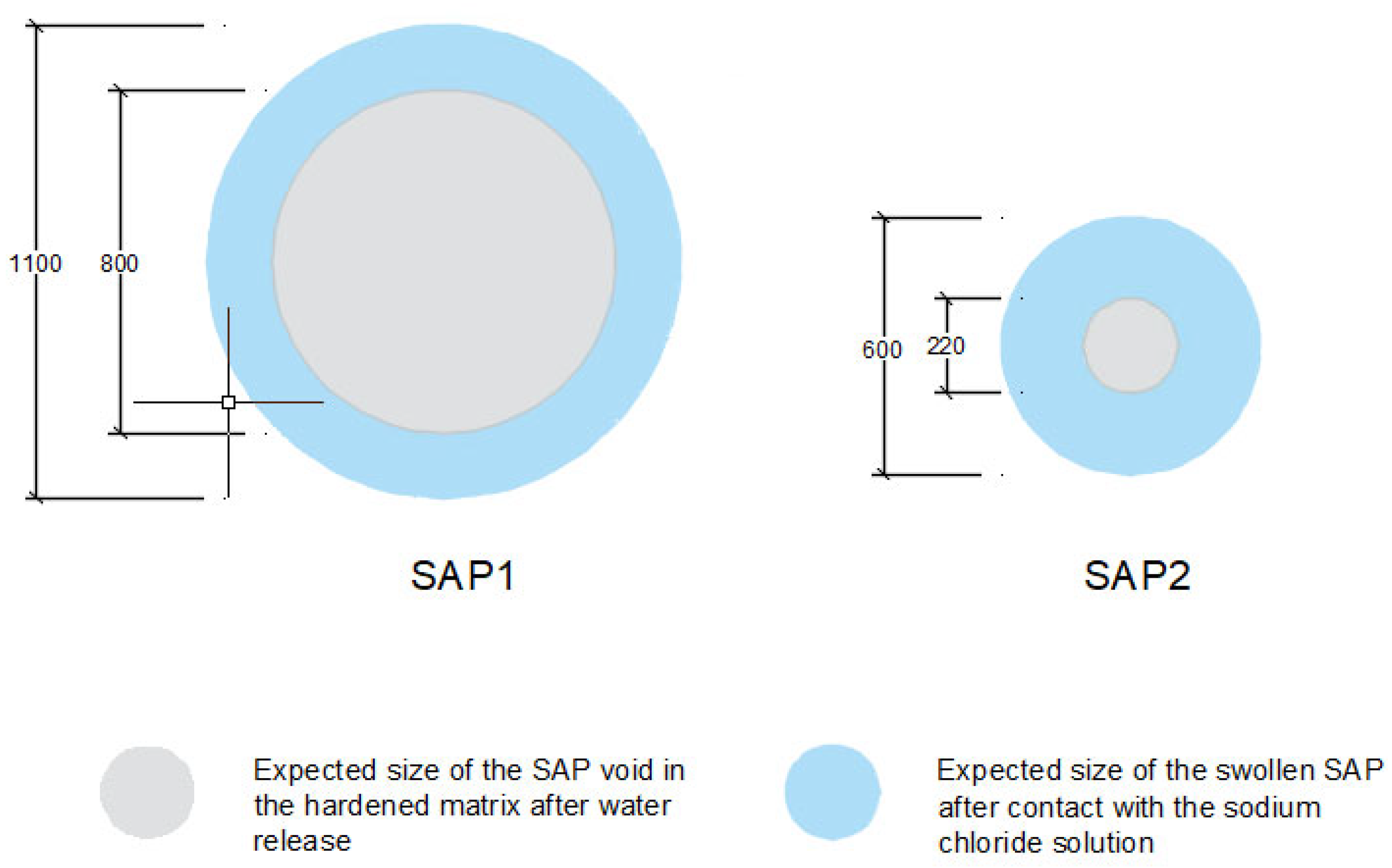
3.3. Absorption Capacity and Swelling and Sealing during Chloride Ingress

In general, for the cracked specimens, it was expected that the presence of SAPs in the cracks could trigger an immediate sealing effect, reducing the crack width and the chloride ingress. However, considering the constant submersion regime, it is likely that the swelling time of the SAPs in the chloride solution was not fast enough to completely seal the cracks and effectively reduce the ingress of the chloride solution. When considering the wet/dry cycles regime, although the overall area affected by the chlorides is numerically similar among the specimens with SAPs and WR1, it is also noticeable that in the SAP mixtures, there seems to be a lower chloride penetration perpendicular to the crack. This might be an indication that the SAPs could be entrapping some of the chloride ions during the wet cycles (as mentioned in Section 3.2.2): SAPs in the vicinity of the crack absorb the chloride solution and swell, and during the dry cycle they release the solution with a lower content of chloride ions, working as a buffer with limited action. This sealing effect was studied in the literature using low-pressure water-permeability testing [3,41,42].
To better understand the possible effects of sealing during chloride ingress, it is important to observe the absorption capacity and swelling of the SAPs during the process. The absorption capacity of both SAPs in the sodium chloride solution (35 g/L) was stable during a monitoring period of 24 h (see Figure 18), with average values around 55 g/g for SAP1 and 37 g/g for SAP2. These values are both superior to those found for the SAPs in cement pastes, 21 g/g and 13 g/g for SAP1 and SAP2, respectively [5]. Considering both values of absorption capacity (in cement paste and sodium chloride solution), the theoretical swelling of the SAP particles can be determined (see Figure 19).
Considering the theoretical size of the swollen particles upon contact with the sodium chloride solution, it could be expected that the presence of either type of SAP would be enough to seal the cracks investigated in this study (crack width of 250 µm). However, there are some conditions that need to be considered. The specimens were cracked under a Brazilian splitting test and the location of the dry SAP particles in the crack may vary: (1) some particles might become loose and separate from the crack; (2) some particles might remain attached to the concrete surface or stuck inside the crack. In the first case, these particles will not take part in the sealing, and for the second case, there is the possibility of the SAPs becoming separated/dislocated from the crack by the ascending and descending flow of the testing solution (in the case of the cracked specimens subjected to wet/dry cycles).
The lower swelling of SAP2 will result in smaller macropores and lower total porosity. This will have less influence on mechanical performance [3]. As SAP1 has been added primarily as an internal curing agent, swelling should be of the same order of magnitude as the one found. The sealing effect is an added benefit. SAP2, however, can be added for purposes other than internal curing, including sealing and healing effects [41], where swelling during mixing is less important. Swelling during sealing and healing must be sufficiently high to induce recovery of impermeability, without reducing the overall mechanical properties to too great an extent. As the swelling of SAP2 is greater than the expected crack width of 300 µm, a reduction in permeability is expected. In addition, both particles are large enough not to be dislocated from the cracks. The combination of the two SAPs will lead to lower autogenous shrinkage (using SAP1) and therefore a lower degree of autogenous shrinkage cracking. This is likely to increase the durability of the overall structure [43]. The eventual development of other types of cracks may benefit from the addition of SAP2. The combination of the two types of SAPs will lead to a stronger overall concrete composition.

4. Conclusions

This study represents one of the largest trial campaigns on SAP concrete walls conducted in Europe to date. Two types of SAPs were studied, one commercially available and the other developed specifically for this study. The first SAP was used to facilitate internal curing of the concrete structure, thereby reducing the possibility of early-age shrinkage-induced cracking. The second SAP was designed to promote immediate crack sealing while improving the concrete’s self-healing capabilities in the case of imminent crack formation. By combining the two SAPs, it was envisaged that an ideal concrete wall could be constructed, with active means of mitigating shrinkage and promoting self-sealing/crack healing.
The internal curing promoted by SAPs had a positive impact, leading to a remarkable 55% reduction in shrinkage strain at 7 days compared with a reference mix without SAPs. As a result, the SAP-treated wall remained crack-free throughout the 24-month monitoring period. The reference walls without SAP, however, showed cracks as early as the first seven days after casting. With regard to corrosion initiation, no indication of corrosion potential was observed in the monitored areas of the SAP-treated wall. On the other hand, a drop in potential, indicating the start of corrosion, was noted in the reference wall near certain cracks 6 months after casting. Although there is no direct reported effect of SAPs on corrosion itself, the prevention of cracking by SAP-enhanced internal curing can be identified as the main factor responsible for the differences in corrosion potential between the two walls. This underlines the positive aspect of using SAPs not only for crack prevention but also for corrosion risk mitigation.
The investigation of the effect of SAPs on (accelerated) carbonation and chloride ingress showed that the increased air void content and porosity expected with the inclusion of SAPs does not necessarily reduce the resistance to carbonation and chloride ingress. On the contrary, if the appropriate type of SAP is used (meaning an SAP with a well-controlled water release) and the correct amount of water is adopted to compensate for the loss in workability due to the absorption of SAPs, then the internal curing is effective, and the presence of the polymers might densify the matrix, thus slightly increasing the resistance to carbonation and chloride ingress.
When cracked specimens are considered, there is a limited sealing effect against chloride ingress, which depends on the exposure regime (whether constantly submerged or in alternating wet/dry cycles), the size of the cracks in relation to the size of the SAP particles, and the swelling potential of the SAPs in the fresh concrete mix and in contact with the chloride solution.
Furthermore, the use of SAPs also represents a more sustainable option by reducing (even avoiding) the need for repair work due to cracking and corrosion, extending the service life of the structure, and limiting the carbon footprint related to the maintenance and repair service commonly demanded for regular structures.

Author Contributions

Conceptualization, J.R.T.F., N.D.B. and D.S.; methodology, J.R.T.F. and D.S.; validation, J.R.T.F. and D.S.; formal analysis, J.R.T.F.; investigation, J.R.T.F.; resources, N.D.B. and D.S.; data curation, J.R.T.F., N.D.B. and D.S.; writing—original draft preparation, J.R.T.F. and D.S.; writing—review and editing, N.D.B. and D.S.; visualization, J.R.T.F.; supervision, N.D.B. and D.S.; project administration, D.S.; funding acquisition, N.D.B. and D.S. All authors have read and agreed to the published version of the manuscript.

Funding

This work has been financed by the SIM program SHE (Engineered Self-Healing Materials) within the ICON project iSAP (Innovative SuperAbsorbent Polymers for crack mitigation and increased service life of concrete structures).

Institutional Review Board Statement

Not applicable.

Informed Consent Statement

Not applicable.

Data Availability Statement

The data presented in this study are available upon reasonable request.

Conflicts of Interest

The authors declare no conflicts of interest. The funders had no role in the design of the study; in the collection, analyses, or interpretation of data; in the writing of the manuscript; or in the decision to publish the results.

References

  1. Mechtcherine, V.; Reinhardt, H.W. Application of Super Absorbent Polymers (SAP) in Concrete Construction, State-of-the-Art Report Prepared by Technical Committee 225-SAP; RILEM, Springer: Dordrecht, The Netherlands, 2012; p. 166. [Google Scholar]
  2. Wong, H.S. Concrete with superabsorbent polymer, In Eco-Efficient Repair and Rehabilitation of Concrete Infrastructures; Pacheco-Torgal, R.E.M.F., Shi, X., De Belie, N., Van Tittelboom, K., Sáez, A., Eds.; Woodhead Publishing: Sawston, UK, 2018; pp. 467–499. [Google Scholar]
  3. Schröfl, C.; Erk, K.A.; Siriwatwechakul, W.; Wyrzykowski, M.; Snoeck, D. Recent progress in superabsorbent polymers for concrete. Cem. Concr. Res. 2022, 151, 106648. [Google Scholar] [CrossRef]
  4. Mechtcherine, V.; Wyrzykowski, M.; Schröfl, C.; Snoeck, D.; Lura, P.; De Belie, N.; Mignon, A.; Van Vlierberghe, S.; Klemm, A.J.; Almeida, F.C.R.; et al. Application of super absorbent polymers (SAP) in concrete construction—Update of RILEM state-of-the-art report. Mater. Struct. 2021, 54, 80. [Google Scholar] [CrossRef]
  5. Tenório Filho, J.R.; Vermoesen, E.; Mannekens, E.; Van Tittelboom, K.; Van Vlierberghe, S.; De Belie, N.; Snoeck, D. Enhanced durability performance of cracked and uncracked concrete by means of smart in-house developed superabsorbent polymers with alkali-stable and -unstable crosslinkers. Constr. Build. Mater. 2021, 297, 123812. [Google Scholar] [CrossRef]
  6. Araujo, M.; Van Vlierberghe, S.; Feiteira, J.; Graulus, G.J.; Van Tittelboom, K.; Martins, J.C.; Dubruel, P.; De Belie, N. Cross-linkable polyethers as healing/sealing agents for self-healing of cementitious materials. Mater. Des. 2016, 98, 215–222. [Google Scholar] [CrossRef]
  7. Mignon, A.; Snoeck, D.; Dubruel, P.; Van Vlierberghe, S.; De Belie, N. Crack Mitigation in Concrete: Superabsorbent Polymers as Key to Success? Materials 2017, 10, 237. [Google Scholar] [CrossRef] [PubMed]
  8. Monnig, S.; Lura, P. Superabsorbent polymers—An additive to increase the freeze-thaw resistance of high strength concrete. In Advances in Construction Materials; Grosse, C.U., Ed.; Springer: Berlin/Heidelberg, Germany, 2007; pp. 351–358. [Google Scholar]
  9. Laustsen, S.; Hasholt, M.T.; Jensen, O.M. Void structure of concrete with superabsorbent polymers and its relation to frost resistance of concrete. Mater. Struct. 2015, 48, 357–368. [Google Scholar] [CrossRef]
  10. Bentz, D.P. Influence of internal curing using lightweight aggregates on interfacial transition zone percolation and chloride ingress in mortars. Cem. Concr. Compos. 2009, 31, 285–289. [Google Scholar] [CrossRef]
  11. Zhutovsky, S.; Kovler, K. Effect of internal curing on durability-related properties of high performance concrete. Cem. Concr. Res. 2012, 42, 20–26. [Google Scholar] [CrossRef]
  12. Carmelo Di Bella, C.V.E.H.; Jason, W. Chloride Transport Measurements for a Plain and Internally Cured Concrete Mixture; ACI Symposium Publication: Farmington Hills, MI, USA, 2012; Volume 290. [Google Scholar]
  13. Hasholt, M.T.; Jensen, O.M. Chloride migration in concrete with superabsorbent polymers. Cem. Concr. Compos. 2015, 55, 290–297. [Google Scholar] [CrossRef]
  14. Ma, X.; Liu, J.; Wu, Z.; Shi, C. Effects of SAP on the properties and pore structure of high performance cement-based materials. Constr. Build. Mater. 2017, 131, 476–484. [Google Scholar] [CrossRef]
  15. Lee, C.K.; Kim, I.S.; Choi, S.S.Y.; Yang, E.I. Evaluation of Fundamental Properties and Chloride Penetration Resistance of Concrete using Superabsorbent Polymers. J. Korea Inst. Struct. Maint. Insp. 2020, 24, 50–59. [Google Scholar]
  16. Dang, J.; Zhao, J.; Du, Z.H. Effect of Superabsorbent Polymer on the Properties of Concrete. Polymers 2017, 9, 672. [Google Scholar] [CrossRef] [PubMed]
  17. Kalinowski, M.; Woyciechowski, P. Chloride Diffusion in Concrete Modified with Polyacrylic Superabsorbent Polymer (SAP) Hydrogel—The Influence of the Water-to-Cement Ratio and SAP-Entrained Water. Materials 2021, 14, 4064. [Google Scholar] [CrossRef] [PubMed]
  18. Van Mullem, T.; De Brabandere, L.; Van de Voorde, E.; Snoeck, D.; De Belie, N. Influence of superabsorbent polymers on the chloride ingress of mortar measured by chloride diffusion and a quasi-steady-state migration test. Cem. Concr. Compos. 2024, 150, 105563. [Google Scholar] [CrossRef]
  19. Tenorio Filho, J.R.; Mannekens, E.; Van Tittelboom, K.; Van Vlierberghe, S.; De Belie, N.; Snoeck, D. Innovative SuperAbsorbent Polymers (iSAPs) to construct crack-free reinforced concrete walls: An in-field large-scale testing campaign. J. Build. Eng. 2021, 43, 102639. [Google Scholar] [CrossRef]
  20. Tenorio Filho, J.R.; Snoeck, D.; De Belie, N. Mixing protocols for plant-scale production of concrete with superabsorbent polymers. Struct. Concr. 2020, 21, 983–991. [Google Scholar] [CrossRef]
  21. Tenório Filho, J.R.; De Belie, N.; Snoeck, D. Reaching Beyond Internal Curing: The Effects of Superabsorbent Polymers on the Durability of Reinforced Concrete Structures. In International RILEM Conference on Synergising Expertise towards Sustainability and Robustness of Cement-based Materials and Concrete Structures; Jędrzejewska, A., Kanavaris, F., Azenha, M., Benboudjema, F., Schlicke, D., Eds.; Springer Nature: Cham, Switzerland, 2023; pp. 933–941. [Google Scholar]
  22. EN 12390-12:2020; Testing Hardened Concrete Determination of the Carbonation Resistance of Concrete. Accelerated Carbonation Method. European Standard: Plzen, Czech Republic, 2020. Available online: https://www.en-standard.eu/bs-en-12390-12-2020-testing-hardened-concrete-determination-of-the-carbonation-resistance-of-concrete-accelerated-carbonation-method/ (accessed on 27 June 2024).
  23. Snoeck, D.; Schröfl, C.; Mechtcherine, V. Recommendation of RILEM TC 260-RSC: Testing sorption by superabsorbent polymers (SAP) prior to implementation in cement-based materials. Mater. Struct. 2018, 51, 116. [Google Scholar] [CrossRef]
  24. ASTM C1581-04:2010; Standard Test Method for Determining Age at Cracking and Induced Tensile Stress Characteristics of Mortar and Concrete under Restrained Shrinkage. ASTM International: West Conshohocken, PA, USA, 2018.
  25. Snoeck, D.; Pel, L.; De Belie, N. The water kinetics of superabsorbent polymers during cement hydration and internal curing visualized and studied by NMR. Sci. Rep. 2017, 7, 9514. [Google Scholar] [CrossRef] [PubMed]
  26. Snoeck, D.; Goethals, W.; Hovind, J.; Trtik, P.; Van Mullem, T.; Van den Heede, P.; De Belie, N. Internal curing of cement pastes by means of superabsorbent polymers visualized by neutron tomography. Cem. Concr. Res. 2021, 147, 106528. [Google Scholar] [CrossRef]
  27. Grasley, Z.C.; Lange, D.A.; D’Ambrosia, M.D. Internal relative humidity and drying stress gradients in concrete. Mater. Struct. 2006, 39, 901–909. [Google Scholar] [CrossRef]
  28. Henkensiefken, R.; Bentz, D.; Nantung, T.; Weiss, J. Volume change and cracking in internally cured mixtures made with saturated lightweight aggregate under sealed and unsealed conditions. Cem. Concr. Compos. 2009, 31, 427–437. [Google Scholar] [CrossRef]
  29. Poursaee, A.; Ross, B. The Role of Cracks in Chloride-Induced Corrosion of Carbon Steel in Concrete—Review. Corros. Mater. Degrad. 2022, 3, 258–269. [Google Scholar] [CrossRef]
  30. Tenorio Filho, J.R.; Mannekens, E.; Van Tittelboom, K.; Snoeck, D.; De Belie, N. Assessment of the potential of superabsorbent polymers as internal curing agents in concrete by means of optical fiber sensors. Constr. Build. Mater. 2020, 238, 117751. [Google Scholar] [CrossRef]
  31. Snoeck, D.; Pel, L.; De Belie, N. Superabsorbent polymers to mitigate plastic drying shrinkage in a cement paste as studied by NMR. Cem. Concr. Compos. 2018, 93, 54–62. [Google Scholar] [CrossRef]
  32. Yang, J.; Guo, Y.; Shen, A.; Chen, Z.; Qin, X.; Zhao, M. Research on drying shrinkage deformation and cracking risk of pavement concrete internally cured by SAPs. Constr. Build. Mater. 2019, 227, 116705. [Google Scholar] [CrossRef]
  33. Yio, M.H.N.; Mac, M.J.; Yeow, Y.X.; Wong, H.S.; Buenfeld, N.R. Effect of autogenous shrinkage on microcracking and mass transport properties of concrete containing supplementary cementitious materials. Cem. Concr. Res. 2021, 150, 106611. [Google Scholar] [CrossRef]
  34. Snoeck, D.; Velasco, L.F.; Mignon, A.; Van Vlierberghe, S.; Dubruel, P.; Lodewyckx, P.; De Belie, N. The effects of superabsorbent polymers on the microstructure of cementitious materials studied by means of sorption experiments. Cem. Concr. Res. 2015, 77, 26–35. [Google Scholar] [CrossRef]
  35. Snoeck, D.; Pel, L.; De Belie, N. Comparison of different techniques to study the nanostructure and the microstructure of cementitious materials with and without superabsorbent polymers. Constr. Build. Mater. 2019, 223, 244–253. [Google Scholar] [CrossRef]
  36. Xu, J.; Qin, X.; Huang, Z.; Lin, Y.; Li, B.; Xie, Z. Effect of Superabsorbent Polymer (SAP) Internal Curing Agent on Carbonation Resistance and Hydration Performance of Cement Concrete. Adv. Mater. Sci. Eng. 2022, 2022, 3485373. [Google Scholar] [CrossRef]
  37. Tenório Filho, J.R.; de Araújo, M.A.P.G.; Mannekens, E.; De Belie, N.; Snoeck, D. Alginate- and sulfonate-based superabsorbent polymers for application in cementitious materials: Effects of kinetics on internal curing and other properties. Cem. Concr. Res. 2022, 159, 106889. [Google Scholar] [CrossRef]
  38. Zhao, C.; Zhang, M.; Liu, Z.; Guo, Y.; Zhang, Q. Salt-Tolerant Superabsorbent Polymer with High Capacity of Water-Nutrient Retention Derived from Sulfamic Acid-Modified Starch. ACS Omega 2019, 4, 5923–5930. [Google Scholar] [CrossRef] [PubMed]
  39. Shah, L.A.; Khan, M.; Javed, R.; Sayed, M.; Khan, M.S.; Khan, A.; Ullah, M. Superabsorbent polymer hydrogels with good thermal and mechanical properties for removal of selected heavy metal ions. J. Clean. Prod. 2018, 201, 78–87. [Google Scholar] [CrossRef]
  40. Bentz, D.P.; Snyder, K.A.; Cass, L.C.; Peltz, M.A. Doubling the service life of concrete structures. I: Reducing ion mobility using nanoscale viscosity modifiers. Cem. Concr. Compos. 2008, 30, 674–678. [Google Scholar] [CrossRef]
  41. Snoeck, D. Superabsorbent polymers to seal and heal cracks in cementitious materials. RILEM Tech. Lett. 2018, 3, 32–38. [Google Scholar] [CrossRef]
  42. Lee, H.X.D.; Wong, H.S.; Buenfeld, N.R. Self-sealing of cracks in concrete using superabsorbent polymers. Cem. Concr. Res. 2016, 79, 194–208. [Google Scholar] [CrossRef]
  43. di Summa, D.; Tenório Filho, J.R.; Snoeck, D.; Van den Heede, P.; Van Vlierberghe, S.; Ferrara, L.; De Belie, N. Environmental and economic sustainability of crack mitigation in reinforced concrete with SuperAbsorbent Polymers (SAPs). J. Clean. Prod. 2021, 358, 131998. [Google Scholar] [CrossRef]
Figure 1. Aerial view (from Google Maps) of the testing site. The black scale bar on the bottom left of the figure amounts to 10 m. The five 14 m long walls are shown on the left-hand side. The description of the wall can be found in the following section.
Applsci 14 06901 g001
Figure 2. Steel reinforcement details of the walls: WR1 on the left and the other walls on the right. Adapted from [19].
Applsci 14 06901 g002
Figure 3. Monitoring the corrosion potential using embedded electrodes.
Applsci 14 06901 g003
Figure 4. Indication of the areas monitored with electrodes and location of cracks in wall WR1.
Applsci 14 06901 g004
Figure 5. Observed cracking in wall WR1, four weeks after the casting, showing the measured height [in mm] and average width [µm].
Applsci 14 06901 g005
Figure 6. Strain/deformation in the WR1 and WSC walls, measured with the embedded fiber optic (SOFO) sensors.
Applsci 14 06901 g006
Figure 7. Restrained shrinkage strain measured in specimens made of WR1 and WSC.
Applsci 14 06901 g007
Figure 8. Use of nickel electrodes to measure the corrosion potential in various locations in wall WR1. The most negative values at locations 37 and 38 were positioned in the vicinity of a crack.
Applsci 14 06901 g008
Figure 9. Potential measurement at various locations in wall WSC.
Applsci 14 06901 g009
Figure 10. The carbonation front is indicated with the colorimetric method. The pink-colored region represents the area not affected by carbonation.
Applsci 14 06901 g010
Figure 11. Average carbonation depth. The error bars represent the standard error of the average.
Applsci 14 06901 g011
Figure 12. Chloride profile visualized by contrast with silver nitrate. The whitish-colored area indicates the presence of chlorides.
Applsci 14 06901 g012
Figure 13. Chloride profiles were measured over the length of the specimen. The measurements were performed from the exposed surface of the specimen every 10 mm.
Applsci 14 06901 g013
Figure 14. Visual aspects of the cracked surface of specimens under continuous immersion.
Applsci 14 06901 g014
Figure 15. Visual aspects of the cracked surface of specimens under wet/dry cycles.
Applsci 14 06901 g015
Figure 16. Chloride ingress profiles of the cracked specimens under continuous immersion.
Applsci 14 06901 g016
Figure 17. Chloride ingress profiles of the cracked specimens subjected to wet/dry cycles in the chloride solution.
Applsci 14 06901 g017
Figure 18. Absorption capacity of SAP1 and SAP2 in the sodium chloride solution (35 g/L).
Applsci 14 06901 g018
Figure 19. Theoretical swelling of the SAP particles in the tested fluids. Dimensions expressed in µm.
Applsci 14 06901 g019
Table 1. Mix design of the concrete mixtures used in the walls (amounts expressed in kg/m³).
WallCementSandLimestoneAd.1Ad.2SAP1SAP2w/ctow/cef
WR136073611162.421.56000.440.44
WR236069510540.950000.520.52
WS136070210782.421.561.3700.520.44
WS236070210782.421.5603.60.540.44
WSC36070210782.421.561.373.60.620.44
The effective water-to-cement ratio (w/cef) refers to the amount of mixing water without considering the additional entrained water in the SAPs. The total water-to-cement ratio (w/cto) refers to the amount of mixing water plus the additional entrained water in the SAPs. Ad.1 refers to the superplasticizer Tixo (25% conc., BASF, Belgium). Ad.2 refers to the superplasticizer Sika-Viscoflow 26 (SIKA, Belgium).
Disclaimer/Publisher’s Note: The statements, opinions and data contained in all publications are solely those of the individual author(s) and contributor(s) and not of MDPI and/or the editor(s). MDPI and/or the editor(s) disclaim responsibility for any injury to people or property resulting from any ideas, methods, instructions or products referred to in the content.

