
Development of Sustainable and Innovative Manhole Covers in Fibre-Reinforced Concrete and GFRP Grating

Abstract
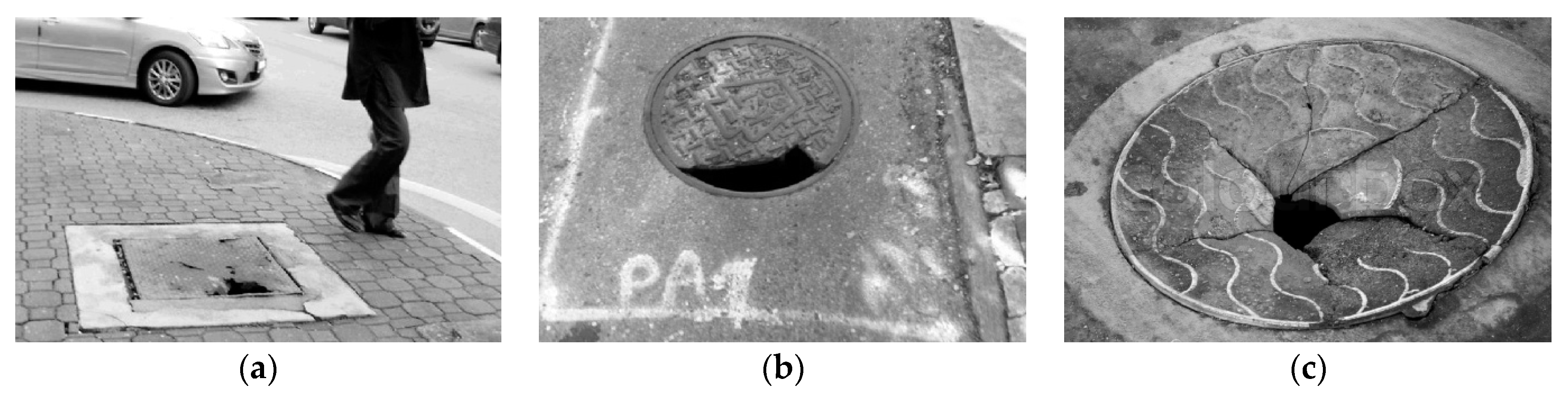
:1. Introduction
2. Experimental Program
2.1. Materials and Structural Concept of the New Manhole Cover
2.2. Test Groups
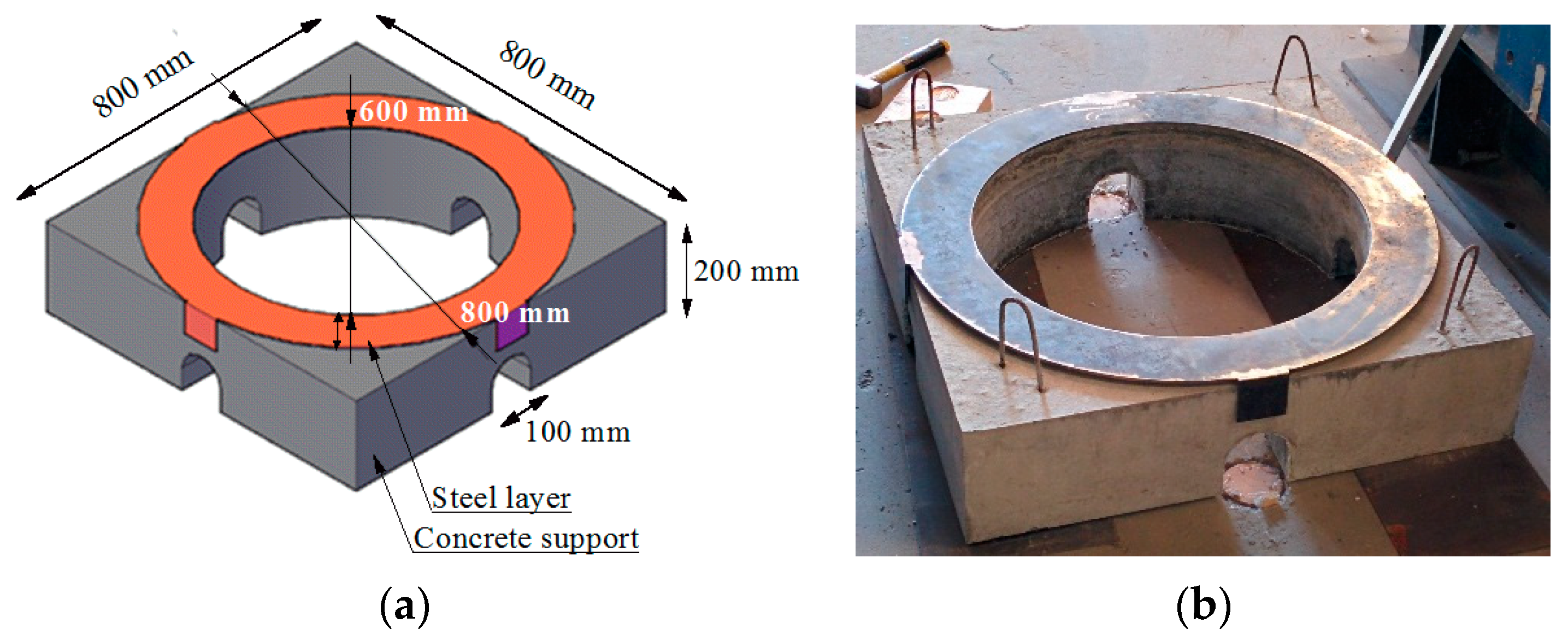
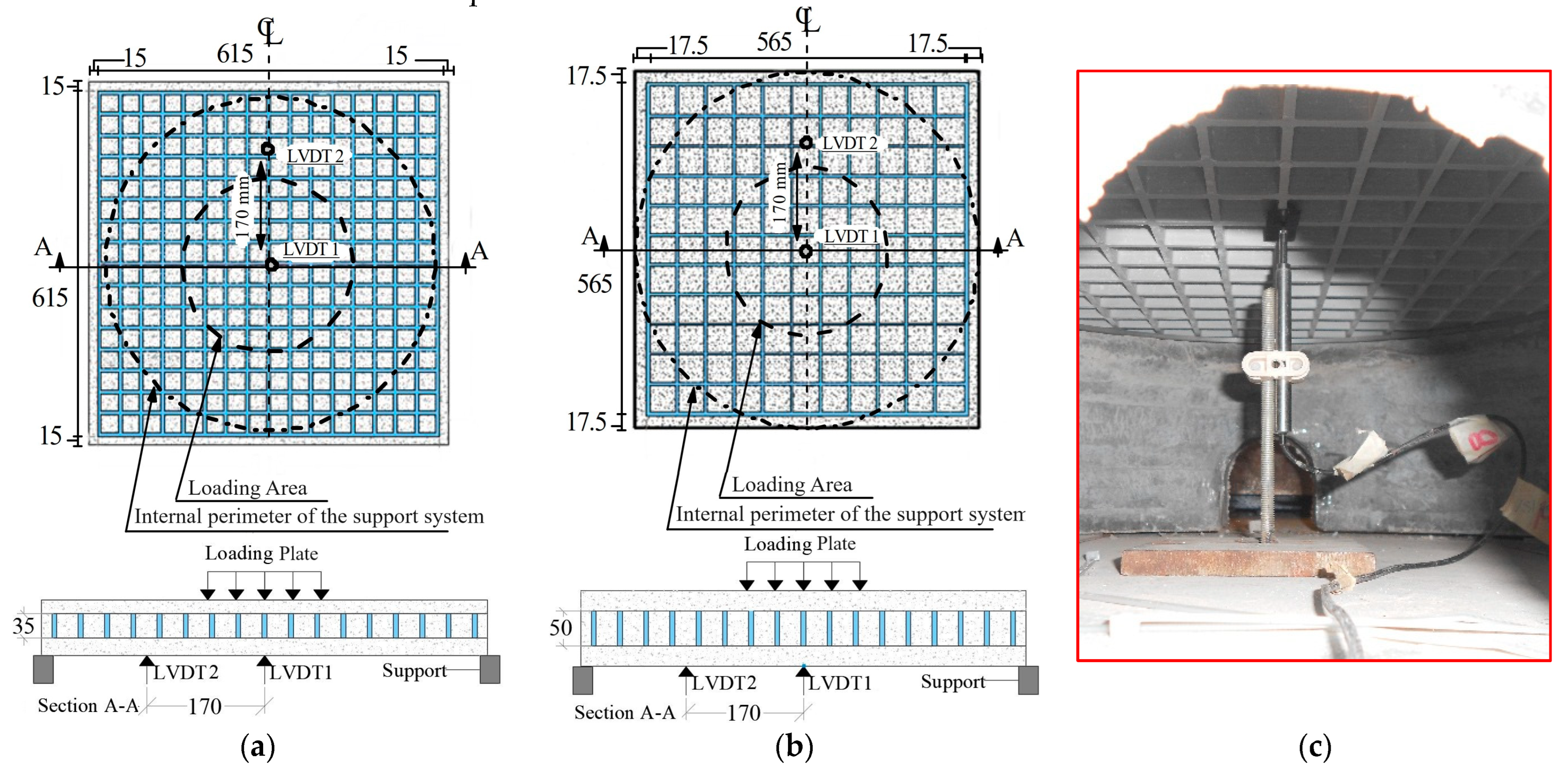
2.3. Test Setup and Monitoring System
2.4. Properties of Constituent Materials and Reinforcing Systems
2.4.1. Fibre-Reinforced Cementitious Materials
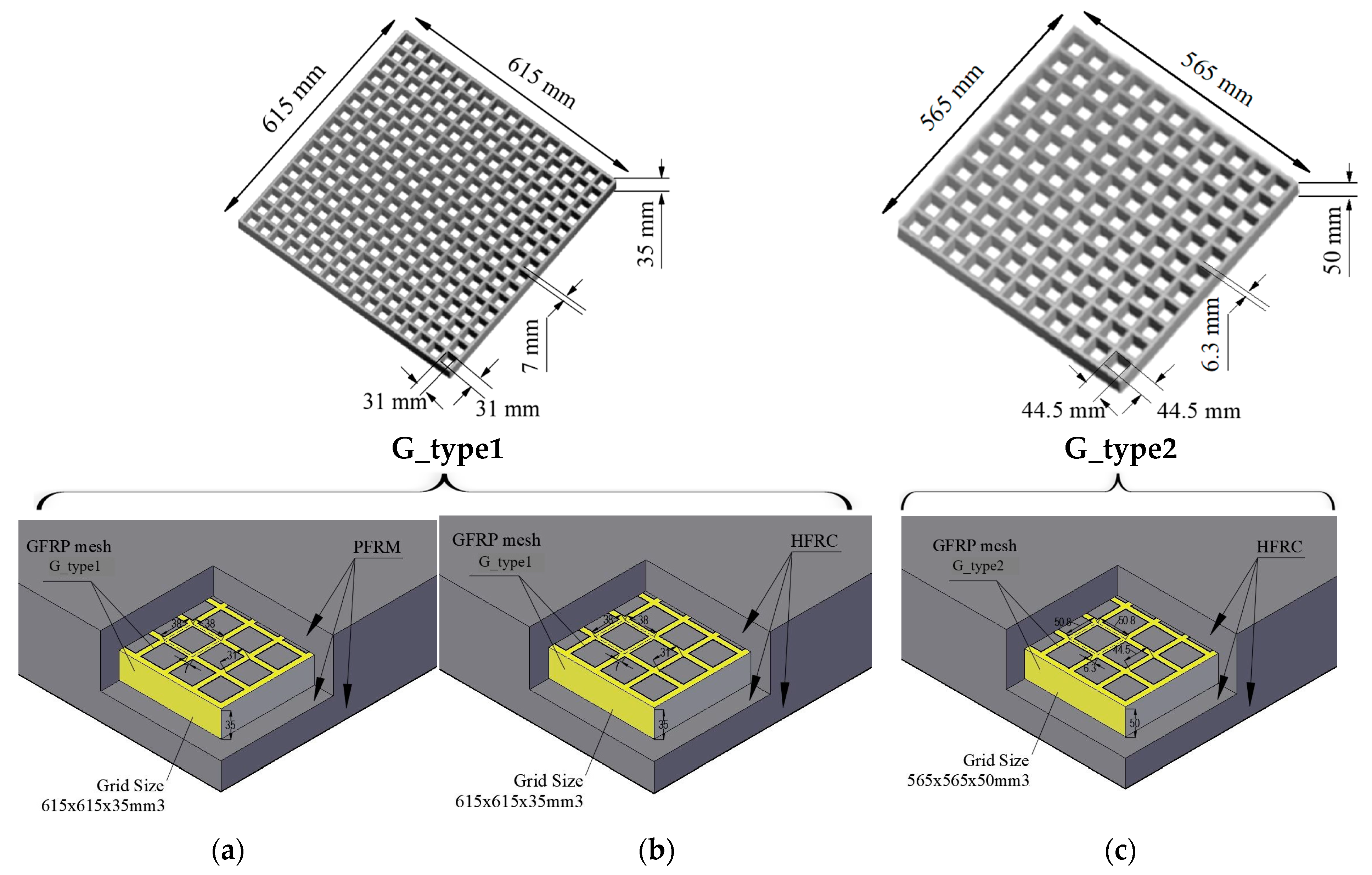
2.4.2. GFRP Gratings
3. Results
3.1. Relevant Results, Failure Modes and Classes
3.2. Influence of the Thickness of the Manhole Specimens in Series with PFRM
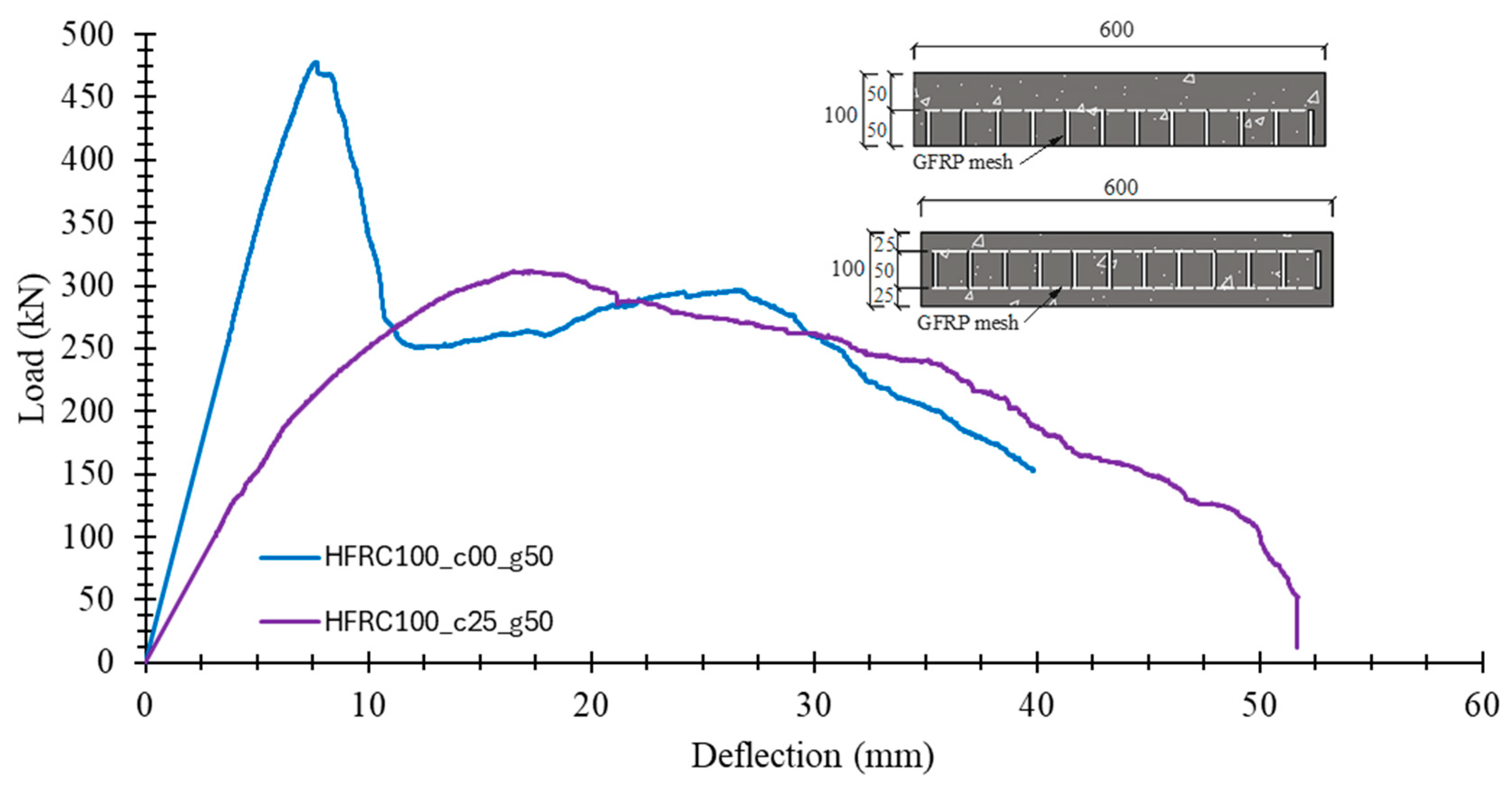
3.3. Influence of the GFRP Grating and Top Concrete Cover Thickness When Using HFRC
3.4. Influence of the FRC Material
3.5. Influence of the Thickness of the Manhole Specimens in Series with HFRC
3.6. Influence of the Concrete Cover Thickness in Series with HFRC and G_type2 Grating
4. Conclusions
- Regarding the influence of the thickness of the manhole specimens in series made by PFRM, an increase of 20 mm in the thickness (20%) has increased the by 54%, and the by 22%. The increase in the thickness was concentrated on the top PFRM cover thickness, demonstrating the influence of this characteristic on the performance of this series of manhole specimens.
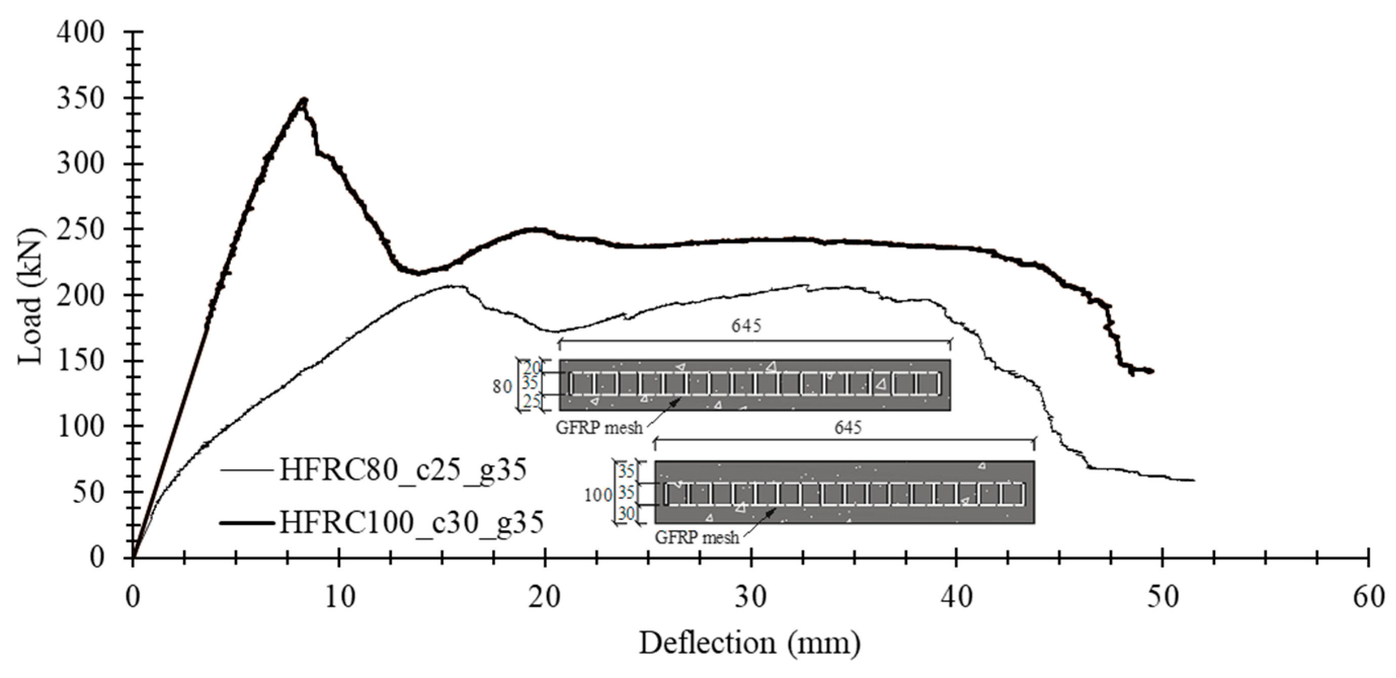
- By testing manhole specimens of the same thickness but different GFRP gratings and top cover thicknesses in the series with HFRC it was verified that the top HFRC cover thickness had a higher impact on the structural performance than the stiffness and load-carrying capacity of the adopted GFRP gratings. This is a consequence of the dominant punching failure mode. It was verified that an increase from 25 mm to 35 mm on the top HFRC cover thickness has provided an increase of 12% and 53% in the and , respectively.
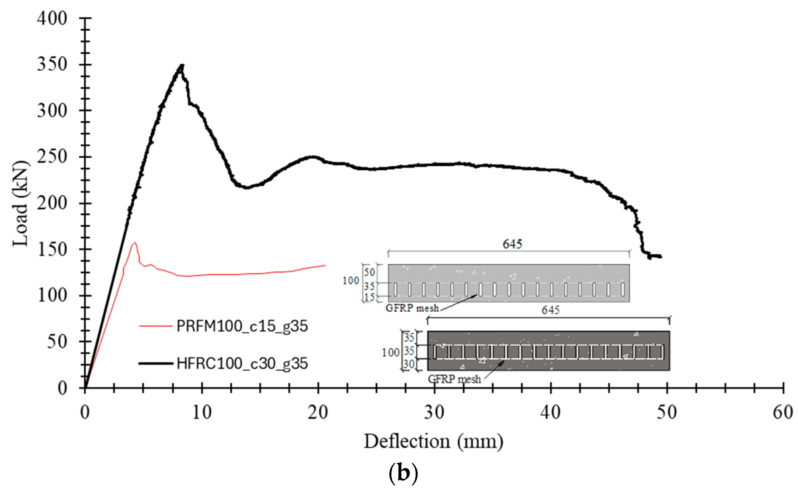
- The use of FRC instead of PFRM has provided an increase of 69% and 92% in terms of and , respectively, in the series with manhole specimens of 80 mm depth; while, in the series with manhole specimens of 100 mm depth, the increase in and was 121% and 32%, respectively.
- In the series made by HFRC, an increase of 20 mm in the manhole specimen thickness (20%) has provided an increase in and of 68% and 48%, respectively. This depth increase was exclusively due to the increase in the top HFRC cover thickness, revealing the influence of this parameter.
- By taking advantage of the immunity of GFRP to corrosion, the highest structural performance of a manhole specimen is obtained by disposing of the G-type2 with null bottom HFRC cover thickness and the largest possible top HFRC cover thickness. Even for a manhole specimen of 100 mm depth (≅24 kg/m2 of deadweight), its class was D400, which means that it can be installed in the highest loaded zones of a highway.
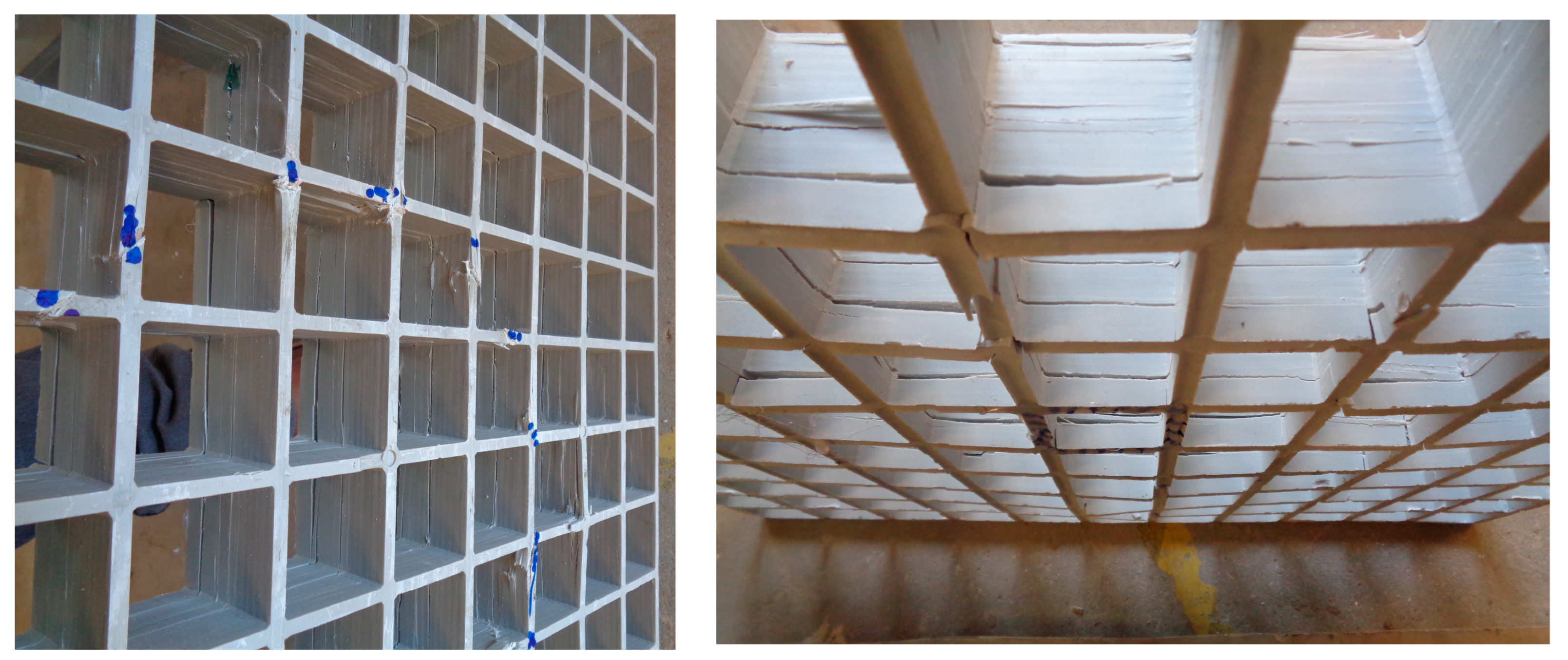
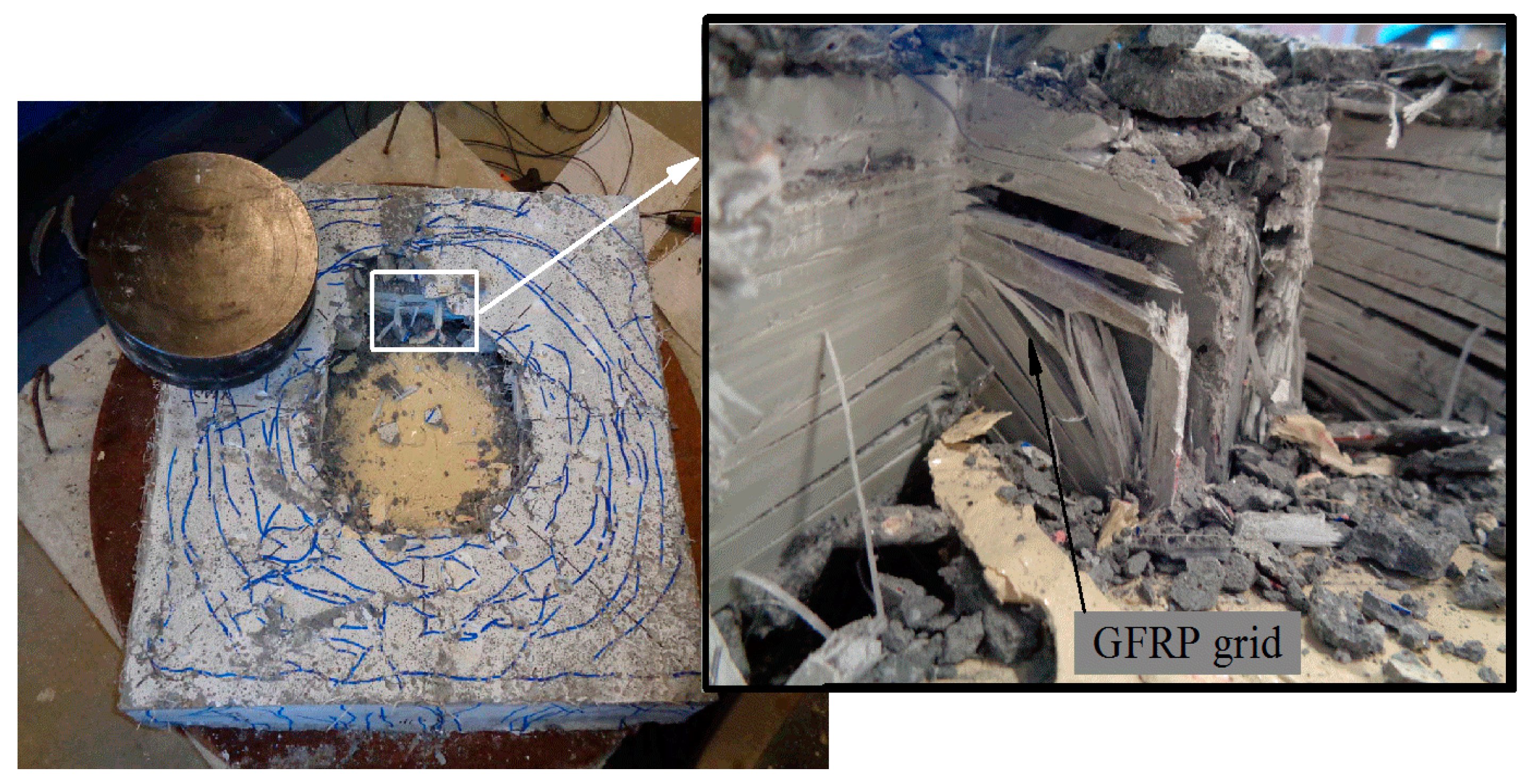
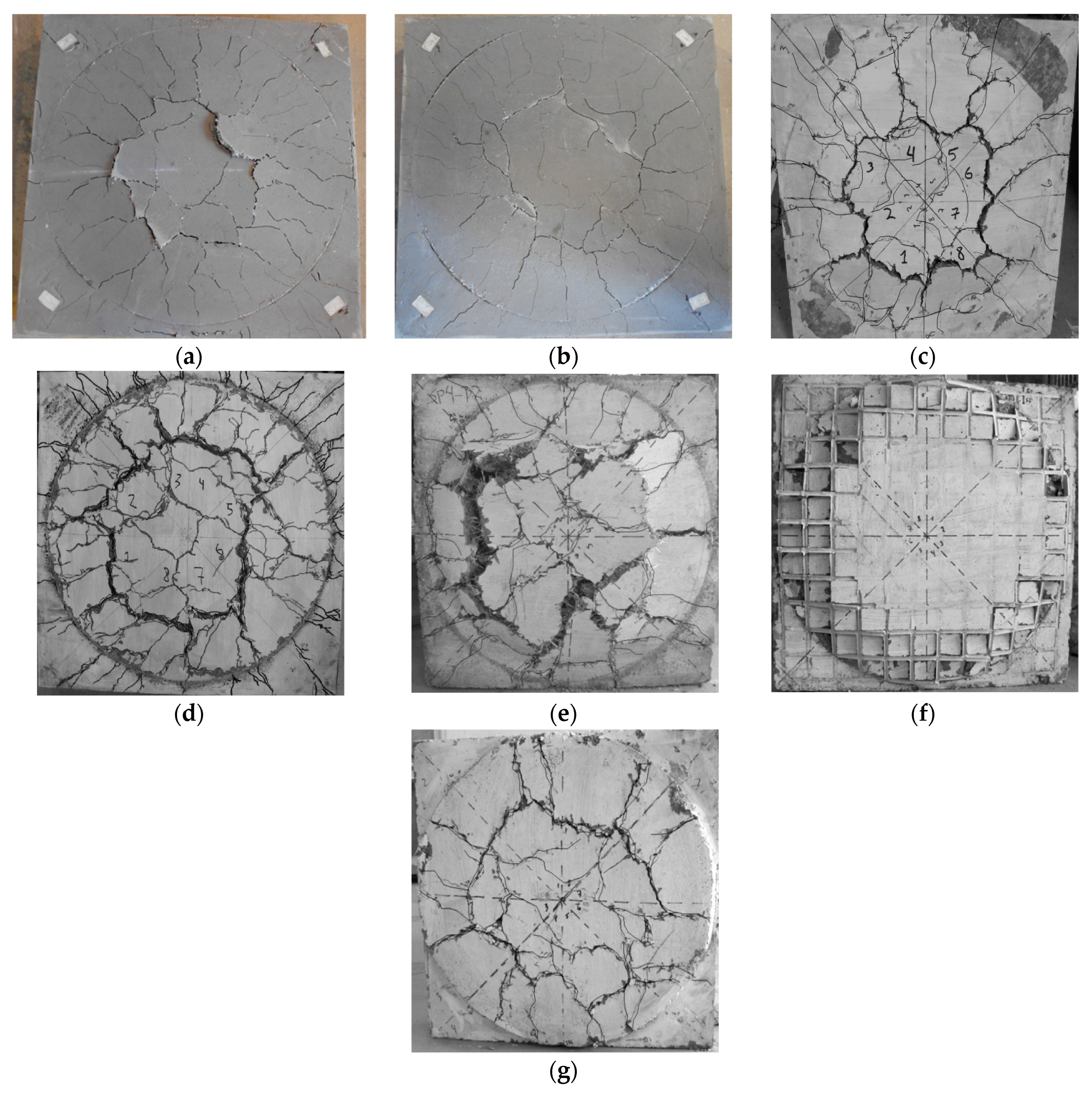
- All manhole specimens failed by punching. Therefore, the stiffness and load-carrying capacity of the tested manhole specimens were dependent on the top concrete cover thickness of the GFRP grating and the type of FRC. In fact, these structural performance indicators have increased with the thickness of the top concrete cover thickness, and with the stiffness and resistance of the FRC.
- Since and increased significantly with the top concrete cover thickness, this characteristic should be taken into account regarding its favourable repercussion in terms of SLS design verifications for deflection.
- All the manhole specimens developed a high level of pseudo-ductility.
Author Contributions
Funding
Institutional Review Board Statement
Informed Consent Statement
Data Availability Statement
Conflicts of Interest
References
- Chrisuné Vermeulen. Manhole Covers Being Stolen to ‘Cover’ Addiction. Available online: https://www.citizen.co.za/witbank-news/news-headlines/2017/12/05/manhole-covers-stolen-cover-addiction/ (accessed on 5 June 2024).
- The Guardian. Ministry Takes Measures to Curb Theft of Manhole Covers on Highways, Bridges. Available online: https://guardian.ng/news/ministry-takes-measure-to-curb-theft-of-manhole-covers-on-highways-bridges/ (accessed on 5 June 2024).
- Davids, N. Manhole Covers Highly Sought-After by Crooks. Available online: https://www.timeslive.co.za/news/south-africa/2017-10-05-manhole-covers-highly-sought-after-by-crooks/ (accessed on 5 June 2024).
- The Times of India. Manhole Lids Go Missing on Trump Route, Officials Get Sinking Feeling. Available online: https://timesofindia.indiatimes.com/city/hyderabad/manhole-lids-go-missing-on-trump-route-officials-get-sinking-feeling/articleshowprint/61681651.cms (accessed on 5 June 2024).
- BBC. Drain Cover Thefts in Reading Pose ‘Public Risk’. Available online: https://www.bbc.com/news/uk-england-berkshire-40159520 (accessed on 5 June 2024).
- Lekea, A.; Steyn, W.J.v. Performance of Pavement Temperature Prediction Models. Appl. Sci. 2023, 13, 4164. [Google Scholar] [CrossRef]
- Mouritz, A.P.; Gibson, A.G. Fire Properties of Polymer Composite Materials; Springer Science & Business Media: Berlin/Heidelberg, Germany, 2007; ISBN 1402053568. [Google Scholar]
- Mastali, M.; Valente, I.B.; Barros, J.A.; Gonçalves, D.M. Development of innovative hybrid sandwich panel slabs: Experimental results. Compos. Struct. 2015, 133, 476–498. [Google Scholar] [CrossRef]
- Gonilha, J.A.; Barros, J.; Correia, J.R.; Sena-Cruz, J.; Branco, F.A.; Ramos, L.F.; Gonçalves, D.; Alvim, M.R.; Santos, T. Static, dynamic and creep behaviour of a full-scale GFRP-SFRSCC hybrid footbridge. Compos. Struct. 2014, 118, 496–509. [Google Scholar] [CrossRef]
- Li, Y.-F.; Badjie, S.; Chen, W.W.; Chiu, Y.-T. Case study of first all-GFRP pedestrian bridge in Taiwan. Case Stud. Constr. Mater. 2014, 1, 83–95. [Google Scholar] [CrossRef]
- Kim, H.-Y.; Lee, S.-Y. A steel-reinforced hybrid GFRP deck panel for temporary bridges. Constr. Build. Mater. 2012, 34, 192–200. [Google Scholar] [CrossRef]
- Da Santos Neto, A.B.S.; La Rovere, H.L. Composite concrete/GFRP slabs for footbridge deck systems. Compos. Struct. 2010, 92, 2554–2564. [Google Scholar] [CrossRef]
- Alnahhal, W.; Aref, A. Structural performance of hybrid fiber reinforced polymer–concrete bridge superstructure systems. Compos. Struct. 2008, 84, 319–336. [Google Scholar] [CrossRef]
- Amin, A.; Foster, S.J. Shear strength of steel fibre reinforced concrete beams with stirrups. Eng. Struct. 2016, 111, 323–332. [Google Scholar] [CrossRef]
- Singh, B.; Jain, K. An Appraisal of Steel Fibers as Minimum Shear Reinforcement in Concrete Beams. ACI Struct. J. 2014, 111, 1191–1202. [Google Scholar] [CrossRef]
- Conforti, A.; Minelli, F.; Plizzari, G.A. Wide-shallow beams with and without steel fibres: A peculiar behaviour in shear and flexure. Compos. Part B Eng. 2013, 51, 282–290. [Google Scholar] [CrossRef]
- Zamri, N.F.; Mohamed, R.N.; Awalluddin, D.; Abdullah, R. Experimental evaluation on punching shear resistance of steel fibre reinforced self-compacting concrete flat slabs. J. Build. Eng. 2022, 52, 104441. [Google Scholar] [CrossRef]
- Barros, J.A.; Moraes Neto, B.N.; Melo, G.S.; Frazão, C.M. Assessment of the effectiveness of steel fibre reinforcement for the punching resistance of flat slabs by experimental research and design approach. Compos. Part B Eng. 2015, 78, 8–25. [Google Scholar] [CrossRef]
- Cheng, M.-Y.; Gustavo, J. Parra-Montesinos. Evaluation of Steel Fiber Reinforcement for Punching Shear Resistance in Slab-Column Connections—Part I: Monotonically Increased Load. ACI Struct. J. 2010, 107, 101–109. [Google Scholar] [CrossRef]
- Di Prisco, M.; Felicetti, R. Some results on punching shear in plain and fibre-reinforced micro-concrete slabs. Mag. Concr. Res. 1997, 49, 201–219. [Google Scholar] [CrossRef]
- Aidarov, S.; Mena, F.; La Fuente, A.d. Structural response of a fibre reinforced concrete pile-supported flat slab: Full-scale test. Eng. Struct. 2021, 239, 112292. [Google Scholar] [CrossRef]
- ACI Committee 544. Design Considerations for Steel Fiber Reinforced Concrete. ACI Struct. J. 1988, 85, 563–579. [Google Scholar] [CrossRef]
- Alexandre, E.; Bouhon, B. Jointless Steel Fiber-Reinforced Concrete Slabs-on-Grade and on Piles. ACI Symp. Publ. 2010, 268, 89–102. [Google Scholar] [CrossRef]
- SP-319: Reduction of Crack Width with Fiber. ACI Symp. Publ. 2017, 319, 178. [CrossRef]
- Fibre Reinforced Concrete: State-of-the-Art Report; fib: Lausanne, Switzerland, 2022; ISBN 978-2-88394-161-8.
- Salehian, H.; Barros, J.A.; Taheri, M. Evaluation of the influence of post-cracking response of steel fibre reinforced concrete (SFRC) on load carrying capacity of SFRC panels. Constr. Build. Mater. 2014, 73, 289–304. [Google Scholar] [CrossRef]
- Cajka, R.; Marcalikova, Z.; Kozielova, M.; Mateckova, P.; Sucharda, O. Experiments on Fiber Concrete Foundation Slabs in Interaction with the Subsoil. Sustainability 2020, 12, 3939. [Google Scholar] [CrossRef]
- El-Gendy, M.; Eisa, A.; El-Sherbiny, M. Performance of fiber reinforced concrete ground slabs under uniform loading conditions. Constr. Build. Mater. 2019, 222, 973–986. [Google Scholar]
- Delgado, N.; Pallarés, L.; Serna, P. Behavior of slab-on-ground floors reinforced with different types of steel fibers. Constr. Build. Mater. 2014, 66, 86–97. [Google Scholar]
- Wu, Y.F.; Zhang, W.X. Performance of polypropylene fiber reinforced concrete in slope stabilization. Constr. Build. Mater. 2023, 23, 212–218. [Google Scholar]
- Paul, B.; Banerjee, A. Fiber reinforced concrete for slope stabilization and landslide mitigation. Int. J. Civ. Eng. Technol. 2013, 4, 147–157. [Google Scholar]
- Patil, R.S.; Desai, V.S. Use of polypropylene fibers in reinforced concrete for slope stabilization. J. Emerg. Technol. Innov. Res. 2018, 5, 351–355. [Google Scholar]
- Ding, Y.; Zhang, H. Experimental study on slope stabilization using steel fiber reinforced concrete. Geotech. Eng. 2010, 119–126. [Google Scholar]
- Liao, L.; Huang, M.; Li, J. Study on mechanical behavior of fiber reinforced concrete used for tunnel lining. Constr. Build. Mater. 2013, 38, 464–472. [Google Scholar]
- Bernard, E.S. Shotcrete linings in weak rock: The influence of fiber reinforcement. Tunn. Undergr. Space Technol. 2000, 15, 167–175. [Google Scholar]
- Pradhan, B. Corrosion behavior of steel reinforcement in concrete exposed to composite chloride–sulfate environment. Constr. Build. Mater. 2014, 72, 398–410. [Google Scholar] [CrossRef]
- Abbasi, A.; Hogg, P.J. Fire testing of concrete beams with fibre reinforced plastic rebar. In Advanced Polymer Composites for Structural Applications in Construction; Elsevier: Amsterdam, The Netherlands, 2004; pp. 445–456. ISBN 9781855737365. [Google Scholar]
- Rosa, I.C.; Firmo, J.P.; Correia, J.R.; Barros, J. Bond behaviour of sand coated GFRP bars to concrete at elevated temperature—Definition of bond vs. slip relations. Compos. Part B Eng. 2019, 160, 329–340. [Google Scholar] [CrossRef]
- Al-Sunna, R.; Pilakoutas, K.; Hajirasouliha, I.; Guadagnini, M. Deflection behaviour of FRP reinforced concrete beams and slabs: An experimental investigation. Compos. Part B Eng. 2012, 43, 2125–2134. [Google Scholar] [CrossRef]
- ACI Committee 440. Guide for the Design and Construction of Structural Concrete Reinforced with Fiber-Reinforced Polymer FRP Bars; American Concrete Institute: Farmington Hills, MI, USA, 2015; ISBN 978-1-942727-10-1. [Google Scholar]
- Mazaheripour, H.; Barros, J.; Soltanzadeh, F.; Sena-Cruz, J. Deflection and cracking behavior of SFRSCC beams reinforced with hybrid prestressed GFRP and steel reinforcements. Eng. Struct. 2016, 125, 546–565. [Google Scholar] [CrossRef]
- BS EN 124:1994; Gully Tops and Manhole Tops for Vehicular and Pedestrian Areas. Design Requirements, Type Testing, Marking, Quality Control. British Standards Institution: London, UK, 1994; ISBN 978-0580227547.
- Fang, H.; Xu, X.; Liu, W.; Qi, Y.; Bai, Y.; Zhang, B.; Hui, D. Flexural behavior of composite concrete slabs reinforced by FRP grid facesheets. Compos. Part B Eng. 2016, 92, 46–62. [Google Scholar] [CrossRef]
- Pournasiri, E.; Pham, T.M.; Hao, H. Behavior of Ultrahigh-Performance Concrete Bridge Decks with New Y-Shape FRP Stay-in-Place Formworks. J. Compos. Constr. 2022, 26, 04022023. [Google Scholar] [CrossRef]
- Nelson, M.; Fam, A. Structural GFRP Permanent Forms with T-Shape Ribs for Bridge Decks Supported by Precast Concrete Girders. J. Bridge Eng. 2013, 18, 813–826. [Google Scholar] [CrossRef]
- He, J.; Liu, Y.; Chen, A.; Dai, L. Experimental investigation of movable hybrid GFRP and concrete bridge deck. Constr. Build. Mater. 2012, 26, 49–64. [Google Scholar] [CrossRef]
- Ziehl, P.H.; Engelhardt, M.D.; Fowler, T.J.; Ulloa, F.V.; Medlock, R.D.; Schell, E. Design and Field Evaluation of Hybrid FRP/Reinforced Concrete Superstructure System. J. Bridge Eng. 2009, 14, 309–318. [Google Scholar] [CrossRef]
- Keller, T.; Schaumann, E.; Vallée, T. Flexural behavior of a hybrid FRP and lightweight concrete sandwich bridge deck. Compos. Part A Appl. Sci. Manuf. 2007, 38, 879–889. [Google Scholar] [CrossRef]
- Correia, J.R.; Branco, F.A.; Ferreira, J. GFRP–concrete hybrid cross-sections for floors of buildings. Eng. Struct. 2009, 31, 1331–1343. [Google Scholar] [CrossRef]
- Ding, L.; Shi, J.; Wang, X.; Sun, S.; Wu, Z. Optimisation of a prestressed fibre-reinforced polymer shell for composite bridge deck. Struct. Infrastruct. Eng. 2019, 15, 454–466. [Google Scholar] [CrossRef]
- Kaklauskas, G.; Sokolov, A.; Barros, J.A.O.d. A design methodology for fibre reinforced concrete elements in serviceability conditions integrating tension softening and stiffening effects. Eng. Struct. 2024, 311, 118199. [Google Scholar] [CrossRef]
- Soltanzadeh, F.; Barros, J.; Santos, R. High performance fiber reinforced concrete for the shear reinforcement: Experimental and numerical research. Constr. Build. Mater. 2015, 77, 94–109. [Google Scholar] [CrossRef]
- BS EN 12350-8:2019; TC: Testing Fresh Concrete—Self-Compacting Concrete. Slump-Flow Test. British Standards Institution: London, UK, 2019; ISBN 9780580984396.
- C01 Committee. Test Method for Compressive Strength of Hydraulic Cement Mortars (Using 2-in. or [50-mm] Cube Specimens); ASTM International: West Conshohocken, PA, USA, 2024. [Google Scholar]
- C09 Committee. Test Method for Static Modulus of Elasticity and Poissons Ratio of Concrete in Compression; ASTM International: West Conshohocken, PA, USA, 2021. [Google Scholar]
- British Standards Institution. Testing Hardened Concrete. Part 13: Determination of Secant Modulus of Elasticity in Compression; British Standards Institution: London, UK, 2021; ISBN 9780539053524. [Google Scholar]
- C09 Committee. Test Method for Compressive Strength of Cylindrical Concrete Specimens; ASTM International: West Conshohocken, PA, USA, 2023. [Google Scholar]
- fib. fib Model Code for Concrete Structures 2010; Wiley: Hoboken, NJ, USA, 2013; ISBN 9783433030615. [Google Scholar]
- Barros, J.A.O. Debilities and strengths of FEM-based constitutive models for the material nonlinear analysis of steel fibre reinforced concrete structures. In Proceedings of the 9th International Conference on Fracture Mechanics of Concrete and Concrete Structures, IA-FraMCoS, Berkeley, CA, USA, 29 May–1 June 2016. [Google Scholar]
- Ventura-Gouveia, A. Constitutive Models for the Material Nonlinear Analysis of Concrete Structures Including Time-Dependent Effects. Ph.D. Thesis, Universidade do Minho, Braga, Portugal, 2011. [Google Scholar]


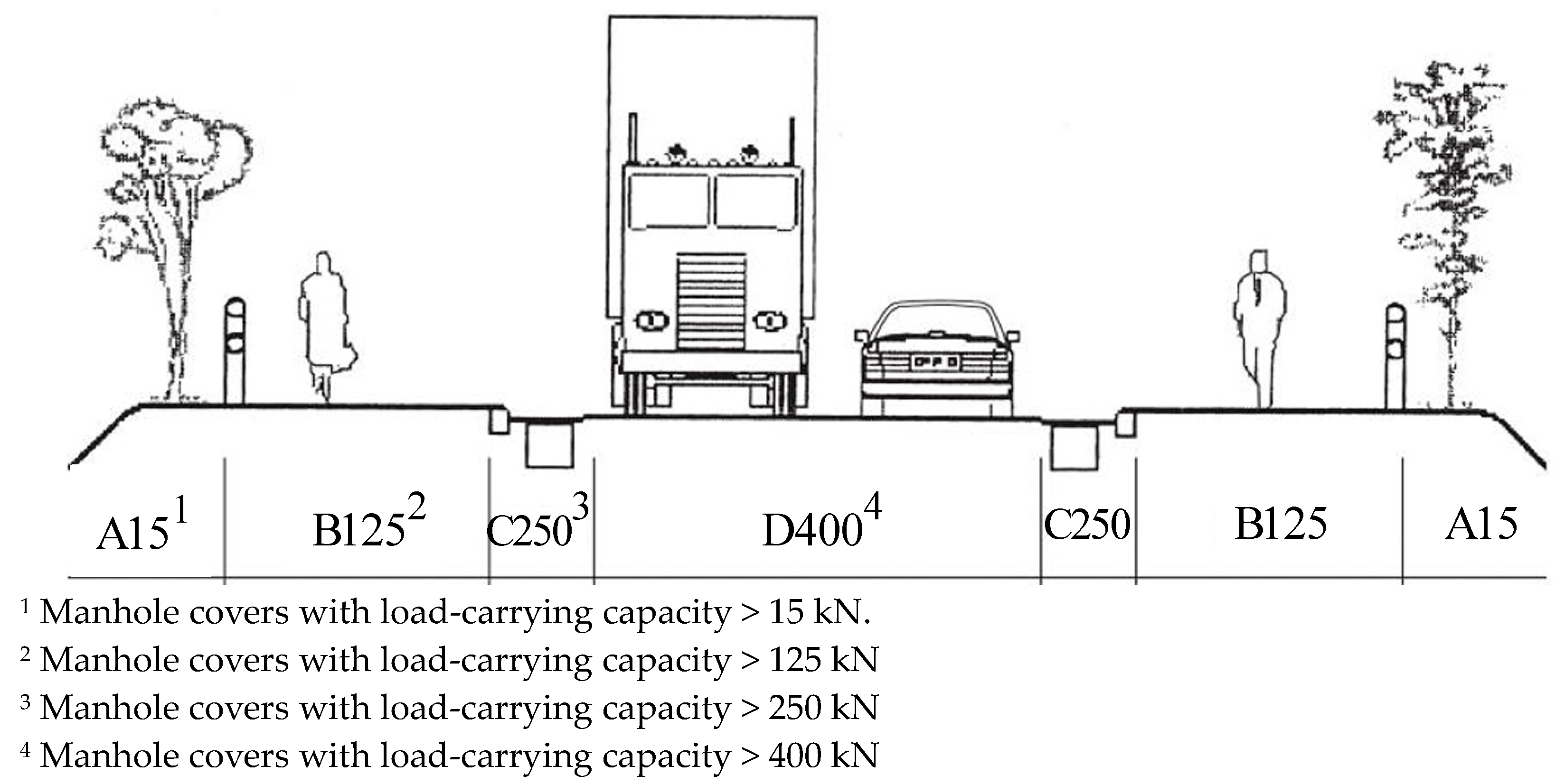
| Class | Application | |
|---|---|---|
| A15 | 15 kN | Areas where only pedestrians have access. |
| B125 | 125 kN | Car parks and pedestrian areas with only occasional vehicular access. |
| C250 | 250 kN | Car parks, industrial sites and areas with slow moving traffic, also in some highway locations. |
| D400 | 400 kN | Areas where cars and lorries have access, including carriageways and hard shoulders. |
| E600 | 600 kN | Areas where high wheel loads are imposed such as docs. |
| F900 | 900 kN | Areas where particularly high wheel load are imposed such as aircraft pavements. |
| Specimen Designation | Type of GFRP | Type of FRC | Geometry and GFRP Position (Cross-Section View) |
|---|---|---|---|
| PFRM80_c15_g35 | G_type1 | PFRM | 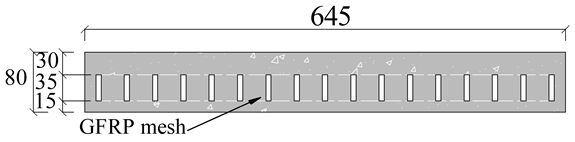 |
| PFRM100_c15_g35 | G_type1 | PFRM |  |
| HFRC80_c25_g35 | G_type1 | HFRC | 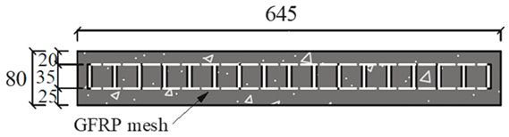 |
| HFRC100_c30_g35 | G_type1 | HFRC |  |
| HFRC100_c25_g50 | G_type2 | HFRC | 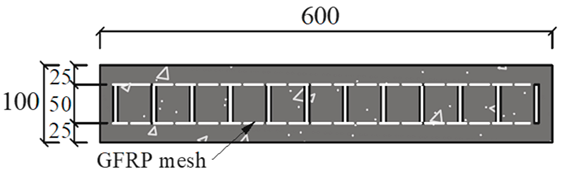 |
| HFRC100_c00_g50 | G_type2 | HFRC |  |
| HFRC110_c40_g50 | G_type2 | HFRC |  |
| Type of Concrete | PFRM | HFRC | ||
|---|---|---|---|---|
| Fibre type | Polyacrylonitrile fibres | Hooked end steel fibres | Polymer macro fibres | |
| PAN6 | PAN12 | |||
| Length (mm) | 6 | 12 | 33 | 54 |
| Diameter (mm) | 0.058 | 0.026 | 0.50 | Not available |
| Elasticity modulus (MPa) | 9910 | 6856 | 210,000 | 7000 |
| Tensile strength (MPa) | 564 | 264.4 | 1100 | 450 |
| Density (g/cm3) | 1.17 | 1.17 | 7.9 | 0.91 |
| Elongation | 13–17 | 14–18 | - | - |
| Composition | PFRM | HFRC |
|---|---|---|
| Cement (kg/m3) | 535 | 462 |
| Fly Ash (kg/m3) | 535 | 139 |
| Limestone Filler (kg/m3) | 102 | 139 |
| Water (L/m3) | 415 | 197 |
| Superplasticizer (L/m3) | 32 | 15.7 |
| Fine river sand (kg/m3) | 214 | 126 |
| Coarse river sand (kg/m3) | - | 670 |
| Coarse aggregate (kg/m3) | - | 512 |
| Steel fibres (kg/m3) | - | 90 |
| Synthetic macro fibres (kg/m3) | - | 3 |
| PAN fibres (kg/m3) | 46.8 | - |
| Viscosity Modification Agent (L/m3) | 0.825 | - |
| [MPa] | [MPa] | [MPa] | [MPa] | [MPa] | |
|---|---|---|---|---|---|
| Average | 13.63 | 13.23 | 13.09 | 11.73 | 10.22 |
| CoV (%) | 23.6 | 12.45 | 10.76 | 11.06 | 15.89 |
| Specimen Designation | [kN] | [mm] | [kN/mm] | [mm] | [mm] | Class According to [42] |
|---|---|---|---|---|---|---|
| PFRM80_c15_g35 | 122.97 | 9.83 | 17.22 | 0.0 | 6.0 | A15 |
| PFRM100_c15_g35 | 157.65 | 4.29 | 37.22 | 0.0 | 6.0 | B125 |
| HFRC80_c25_g35 | 208.10 | 32.71 | 33.13 | 0.8 | 6.0 | B125 |
| HFRC100_c30_g35 | 349.96 | 8.32 | 49.12 | 0.0 | 2.0 | C250 |
| HFRC100_c25_g50 | 311.65 | 17.36 | 31.66 | 0.3 | 2.0 | C250 |
| HFRC100_c00_g50 | 478.08 | 7.62 | 68.88 | 0.0 | 2.0 | D400 |
| HFRC110_c40_g50 | 423.87 | 15.40 | 46.83 | 1.2 | 2.0 | D400 |
Disclaimer/Publisher’s Note: The statements, opinions and data contained in all publications are solely those of the individual author(s) and contributor(s) and not of MDPI and/or the editor(s). MDPI and/or the editor(s) disclaim responsibility for any injury to people or property resulting from any ideas, methods, instructions or products referred to in the content. |
© 2024 by the authors. Licensee MDPI, Basel, Switzerland. This article is an open access article distributed under the terms and conditions of the Creative Commons Attribution (CC BY) license (https://creativecommons.org/licenses/by/4.0/).
Share and Cite
Barros, J.A.O.; Soltanzadeh, F.; de Sousa, C.; Vera, M.O. Development of Sustainable and Innovative Manhole Covers in Fibre-Reinforced Concrete and GFRP Grating. Appl. Sci. 2024, 14, 6903. https://doi.org/10.3390/app14166903
Barros JAO, Soltanzadeh F, de Sousa C, Vera MO. Development of Sustainable and Innovative Manhole Covers in Fibre-Reinforced Concrete and GFRP Grating. Applied Sciences. 2024; 14(16):6903. https://doi.org/10.3390/app14166903
Chicago/Turabian StyleBarros, Joaquim A. O., Fatemeh Soltanzadeh, Christoph de Sousa, and Mónica O. Vera. 2024. "Development of Sustainable and Innovative Manhole Covers in Fibre-Reinforced Concrete and GFRP Grating" Applied Sciences 14, no. 16: 6903. https://doi.org/10.3390/app14166903