Article

In Situ Monitoring and Analysis of the Development Characteristics of Separation in Internal Overburden

1
State Key Laboratory for Fine Exploration and Intelligent Development of Coal Resources, China University of Mining and Technology, Xuzhou 221116, China
2
School of Mines, China University of Mining and Technology, Xuzhou 221116, China
3
School of Resources and Geoscience, China University of Mining and Technology, Xuzhou 221116, China
*
Author to whom correspondence should be addressed.
Appl. Sci. 2024, 14(16), 6935; https://doi.org/10.3390/app14166935
Submission received: 8 July 2024 / Revised: 4 August 2024 / Accepted: 6 August 2024 / Published: 8 August 2024

Abstract

:
This study conducted in situ monitoring by means of distributed optical fiber sensors (DOFS) and multipoint borehole extensometers (MPBXs). Combined with the measurement data of water level depth, the development of separation was analyzed comprehensively for the first time. At first, the development height of the water-conducting fracture zone was predicted. As the results show, the predictive data is 173.95 m. According to the in situ monitoring data, the top boundary height of the water-conducting fracture zone is determined at a height of 186.1~207.9 m, which is in line with the predicted results. Based on the DOFS data, it can be inferred that the separation layer exists at the depths of 351.3~390.4 m. According to MPBXs data, the largest development of the separation layer is also inferred to be located at the depths of 324~388 m. The in situ monitoring methods in this study can directly obtain the development position of the separation layer in the internal overburden, which can provide good guidance for the on-site control of water disasters caused by water accumulation in separation.

1. Introduction

With the increase in coal mining depth, there are some water inrush accidents caused by separation seepers after mining [1,2]. As the working face advances, the different strata in the overburden may subside unevenly, thus forming a large number of transverse separation voids. Once these voids are recharged gradually by the surrounding weak aquifer, more and more water will accumulate in the separation layer. Some aquiclude of certain thickness exists between the separation seeper and caving fracture zone. When the pressure of the separation seeper exceeds the critical pressure value of the aquiclude, water inrush from the separation layer would occur. This kind of water inrush is characterized by its sudden, instantaneous, and large water inflow, but it declines fast, for it is mainly from static reserves. The formation of a separation seeper is the main reason for the increase in water inflow in the working face. This kind of disaster poses severe challenges to the safety production of the working face. However, due to the large workload, the prevention and control of a separation seeper is very hard.
Xu et al. studied the bed separation distribution and development in the process of strata movement [3]. Theoretical analysis, numerical simulation, and borehole drilling were used to study the mechanism of large-scale water inrush events [4]. Li et al. studied the prevention and mechanism of bed separation water inrush for thick coal seams [5]. Strata behavior monitoring was carried out using remote-type geotechnical instruments during the extraction of pillars in one of the panels [6]. The theoretical pattern of ground movement observed in flat terrains was modified by surface topography and geological structures [7]. Using the ‘three maps-two predictions’ method, an index model of water abundance (yield) of the overlying aquifers was constructed and overlain on a map that indicates potential fractured zone connections to the overlying aquifers [8]. The presence of spatially discrete, stiff roof units is one feature that has been linked to dynamic failure events [9].
An analysis of spatial differences in permeability based on sedimentary and structural features of the sandstone aquifer overlying coal seams was undertaken [10]. Three coal mines in the Ordos Basin were selected for a detailed evaluation of the water inrush risk [11]. Zones of interconnected fractures and separate horizontal fractures were studied with vertical wells drilled from the ground surface down to active underground workings [12]. The locations of mining-induced horizontal fractures along rock interfaces in the overburden were identified using an original experimental device [13]. Gui et al. categorized bed separations and indicators of threatening situations and analyzed the morphological evolution of bed separation [14]. Hydrogeological Classification and Water Inrush Accidents in China’s Coal Mines were made [15]. Injecting grout into the bed separation in the overburden was proposed as an effective control measure against surface subsidence during longwall mining [16]. Through engineering geology investigation and theoretical analysis, the mechanism of abnormal water inrush in the roof of the working face under the condition of giant thick igneous rock cover in Haizi mine is researched [17]. Abbas et al. made a prediction of the height of the destressed zone above the mined panel roof in longwall coal mining [18]. The water-resistant key strata stability has been detected by optic fiber sensing in shallow-buried coal seams [19]. A new estimating approach for vertical bedding separation, which uses the ratio between current and average vertical bedding separation was proposed [20]. A water-resistant key strata model of a goaf floor prior to main roof weighting was developed to explore the relationship between water inrush from the floor and main roof weighting [21]. An example of an adapted methodology is described for shale gas/oil resource estimation to include a vertical separation or ‘stand-off’ zone between the deepest mine workings [22].
With an extra-thick working face as the research object, this study conducted in situ monitoring by means of distributed optical fiber sensors (DOFS) and multipoint borehole extensometers (MPBXs). On this basis, combined with the measurement results of water level depth in adjacent boreholes, the development law of separation layers in the overlying strata was analyzed comprehensively for the first time.

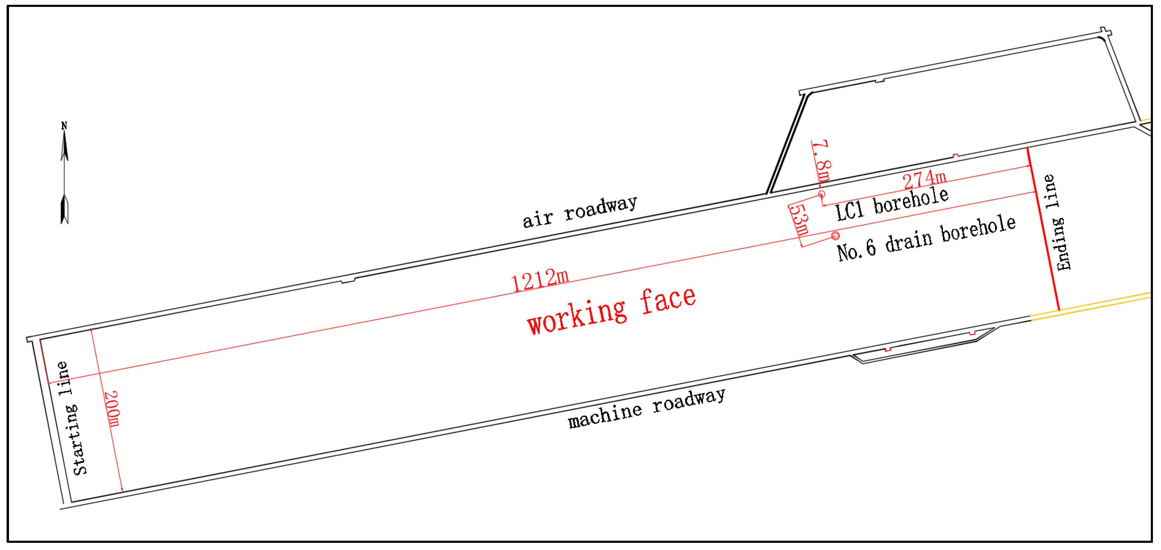
2. The General Situation of the Working Face

The coal seam of the Jurassic Yan’an Formation is mined on a working face with a strike length of 1212 m (the distance from the cut hole to the design stop-mining line) and a dip length of 200 m. The working face plan is shown in Figure 1. The height of the coal seam floor is 630~745 m, and the average burial depth is 653 m. The occurrence of the coal seam is relatively stable, and the thickness of the mined coal seam is 14.0 m.
There are two direct aquifers in the overlying strata of this working face: Zhiluo Formation and Yan’an Formation. According to the results of the pumping test, the unit water inflow and permeability coefficient show that the direct aquifers are weak aquifers. As is revealed by the analysis of the working face, during coal mining, water enters the working face mainly in two forms: drenching and dripping. It is estimated that the normal water inflow is 1~3 m3/h and the maximum is 5 m3/h, whose impact on the working face is relatively weak. According to the results of roof water inrush measured previously, the Lo-ho Formation in the overlying strata of the working face, as an indirect water-filling aquifer, mainly breaks into the working face in the form of a separation seeper. This poses a great threat to the safe production of the working face.
In view of the specific mining conditions of the working face, the in situ monitoring methods of DOFS and MPBXs arranged inside the ground boreholes were used to monitor the movement deformation characteristics of different thicknesses and hardness strata along with the mining of the working face. Combined with the measurement results of the water level depth of adjacent boreholes, this study provided certain supporting data for the accurate judgment of the separation layer development and effective instructions for the in situ prevention and control of water inrush damage.
The location of the monitoring borehole is determined according to the mining conditions of the working face, the key strata discrimination software was used to discriminate the key strata distribution of the LC1 borehole and No. 6 drainage hole. Combined with the columnar logging results of LC1 and No. 6 drainage holes, the corresponding key strata distribution was obtained (as shown in Figure 2).
As can be found from the key strata distribution in the two boreholes, the total number of key strata in the two borehole columns is not many. The key strata are relatively thick, and the structural characteristics of the main key strata are obvious.

3. In Situ Monitoring Program

3.1. Principle of Monitoring

A coupling monitoring technology of DOFS and MPBXs was used to realize real-time monitoring of the internal motion deformation parameters of whole columnar overburden in the process of coal mining. On account of its continuity and high sensitivity, DOFS can collect the micro-strain of any rock strata inside the whole borehole. However, since its non-deformability is rather limited, once the overburden deformation of a certain stratum in the borehole exceeds the strain limit of the optical fiber, it will be broken, thus failing to monitor the overburden deformation below the breakpoint. On the other hand, MPBXs cannot monitor the deformation of all strata in the borehole because of its discreteness, but it has the characteristics of a large range and is not easy to break by overburden deformation. In this sense, MPBXs can continuously collect the overlying rock deformation data at the set stratum. The coupling in situ monitoring technology of DOFS and MPBXs can provide a good research method for mastering the movement law of overlying strata.

3.2. On-Site Implementation

Six monitoring lines of MPBXs and two symmetrical DOFS cables were arranged inside the LC1 borehole. The schematic diagram of monitoring points and monitoring lines is shown in Figure 3. Based on the logging results of the borehole, the key strata discrimination was carried out, and each monitoring point in the borehole was set and adjusted. The depth of MPBXs (from No. 1 to 6) corresponding to the 6 displacement monitoring lines was 534 m, 520 m, 492 m, 453 m, 388 m, and 324 m successively (according to 127 m, 141 m, 169 m, 208 m, 273 m, and 337 m, respectively, above the roof of the coal seam). The depth of the double-circuit DOFS cables is the same as that of 1# MPBX, which is 534 m. The installation scheme is shown in Figure 3, and the on-site installation of the monitoring instruments is shown in Figure 4.
The monitoring instruments have been installed and debugged since the completion of borehole sealing. The official monitoring began on 24 July 2022, when the LC1 borehole was 18 m in front of the working face. By 11 November 2022, the mining of the working face has been completed. The working face has pushed 274 m past the borehole, and the accumulative monitoring time is 110 d.

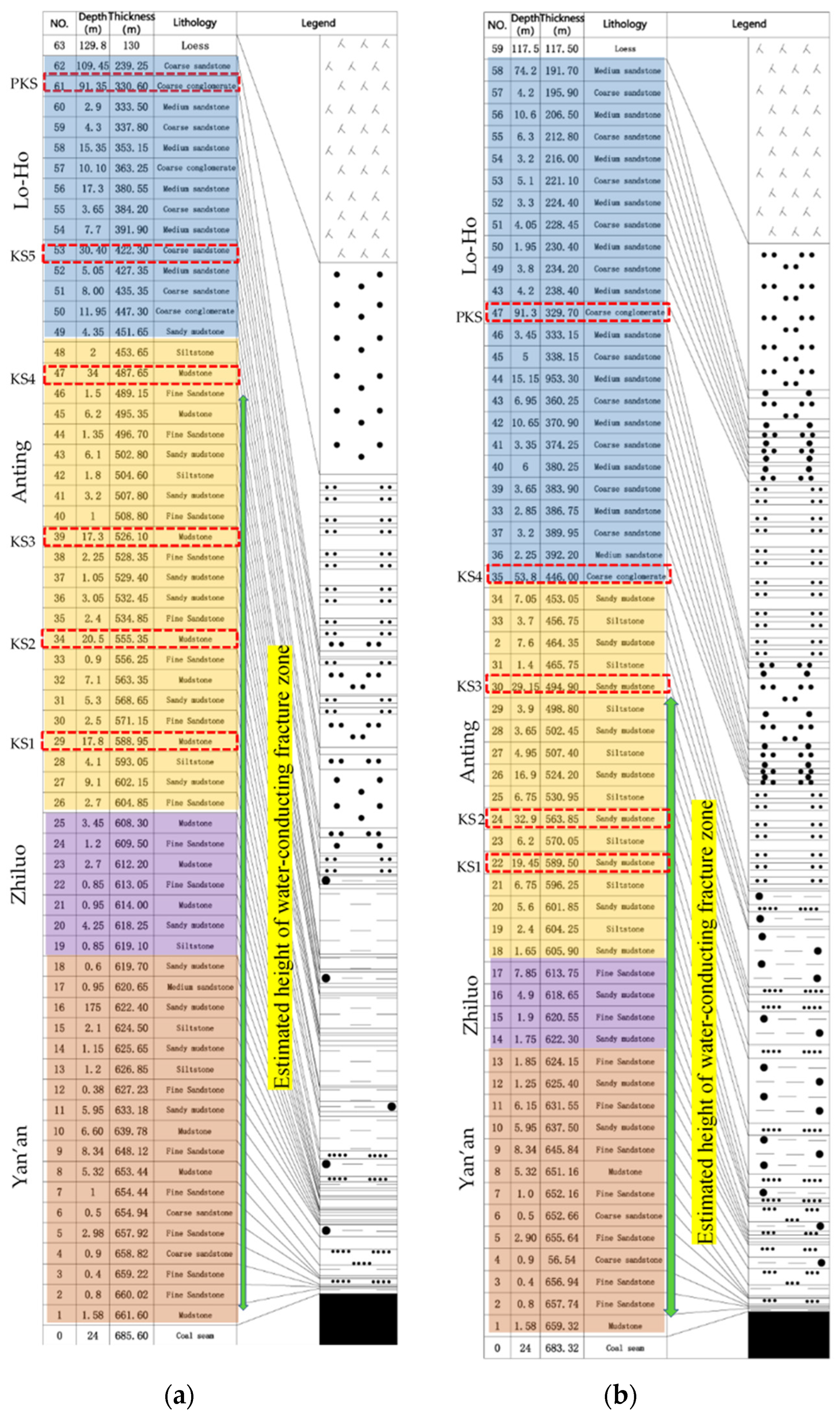
4. The Estimated Height of Overburden Water-Conducting Fracture Zone

As the coal seam is mined, rock failure and deformation occur in the overlying strata, which can be divided into three characteristic parts from the bottom to the top: caving zone, fracture zone, and subsidence zone, namely the “three zones”.
Xu et al. proposed a method of predicting the height of an overburdened water-conducting fracture zone based on key strata position [22]. In this study, this method was used to predict the height of the water-conducting fracture zone in the LC1 borehole and No. 6 drainage hole. In the calculation process, the actual mining height was set to about 10.5~14 m. Accordingly, the overlying water-conducting fracture zone of the LC1 borehole develops to the bottom interface of KS4. The corresponding height of the water-conducting fracture zone is 173.95 m, about 12.4~16.7 times the mining height. The overlying water-conducting fracture zone of the No. 6 drainage hole develops to the bottom interface of KS3. The corresponding height of the water-conducting fracture zone is 164.42 m, about 11.7~15.6 times the mining height. The top interface of the estimated water-conducting zone height of the two boreholes was located in the upper section of the Anting Formation (seen in Figure 3).

5. In Situ Monitoring Result
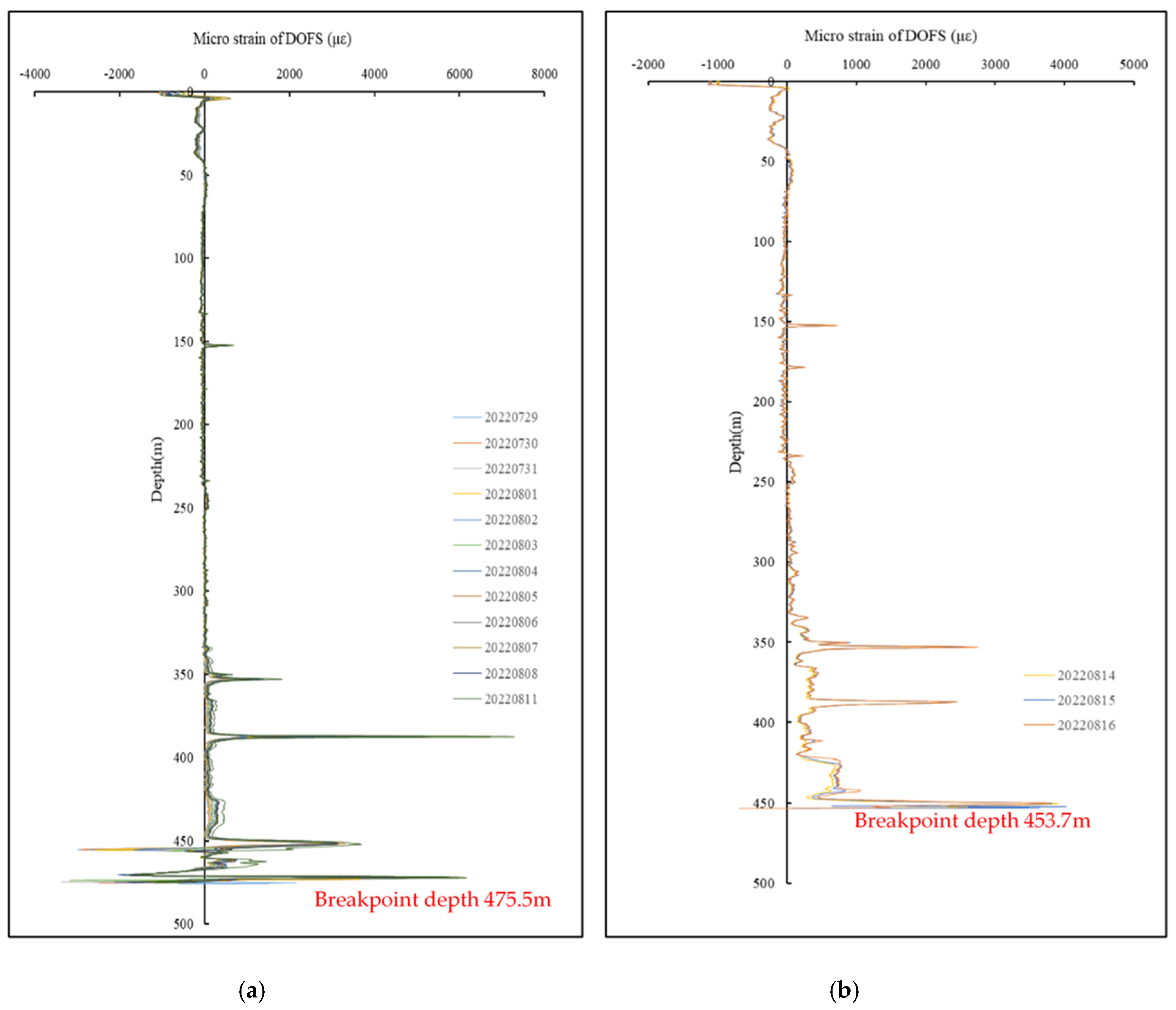
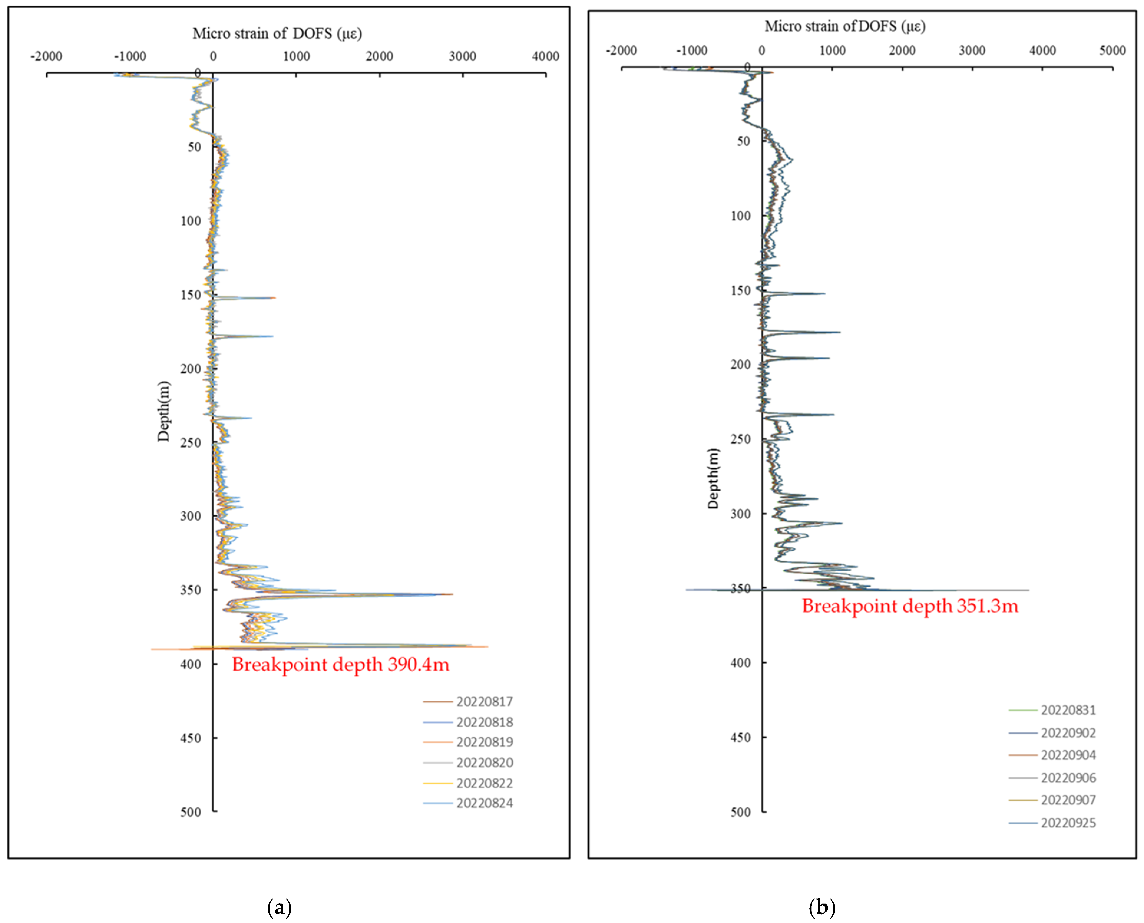
5.1. DOFS Data

DOFS are mainly used to monitor the micro-strain inside the rock strata. However, when a large deformation occurs in the strata, the DOFS may break once the deformation exceeds its strain limit. In that case, the rock deformation below the breakpoint cannot be monitored.
On 24 July 2022, the first round of DOFS monitoring was conducted, followed by the second round on 29 July 2022. During this period, the distance between the LC1 borehole and the working face is −18.4~−0.1 m (negative value indicates advance). Through the analysis of the results obtained in the second round of monitoring, it was found that a strain breakpoint of DOFS occurred at a depth of 475.5 m. This indicated that deformation occurred in the stratum in that position and the deformation amplitude exceeded the strain limit of DOFS. Since the borehole was in an advanced state, the DOFS rupture were caused by the compression deformation of rock strata under the influence of mining advances.
The strain monitoring was carried out continuously every day from 30 July to 11 August 2022, during which the working face advanced past the LC1 borehole by 2.9~38.4 m. According to the monitoring results (Figure 5a), the breakpoint depth of DOFS at this stage remained around 475.5 m, with no change. The overburden deformation was not obvious in the drilling range of 0–350 m, while tensile strain segments appeared repeatedly at the borehole depth of 350 m, 390 m, 450 m, and so on. It can be seen from Figure 5a that there is a compression-tensile strain transition zone at a depth of 450~460 m.
According to the monitoring results obtained on 14 August 2022, a new breakpoint appeared in the DOFS at the depth of 453.7 m (located in the compression-tensile strain transition zone at the depth of 450~460 m in the previous stage). Then, the monitoring was conducted continuously till 16 August 2022, during which the working face advanced past LC1 borehole by 52.6~64.3 m. According to the monitoring results (Figure 5b), the strain of DOFS at this stage was mainly tensile deformation, and the breakpoint depth of DOFS remained around 453.7 m without any change. The overburden deformation was still not significant in the drilling range of 0~350 m, but tensile strain segments appeared repeatedly at the drilling depth of 350 m, 390 m, and so on. It can be seen from Figure 5b that obvious tensile deformation existed at a depth of 385~392 m.
According to the monitoring results obtained on August 17, 2022, a new breakpoint appeared in the DOFS at the depth of 390.4 m (located in the tensile deformation zone at the depth of 385~392 m in the previous stage). Then, the monitoring was conducted continuously till 24 August 2022, during which the working face advanced past the LC1 borehole by 70.4~101 m. According to the monitoring results (Figure 6a), the strain of DOFS at this stage was mainly tensile deformation, and the breakpoint depth of the strain curve remained around 390.4 m. Slight tensile deformation occurred in the overlying strata in the drilling depth of 0~350 m. However, at the depth of 350 m, the tensile deformation was significantly larger than that of the above overlying strata. In addition, it can be seen from Figure 6a that obvious tensile deformation existed at a depth of 350~360 m.
According to the monitoring results obtained on 31 August 2022, a new breakpoint appeared in the DOFS at the depth of 351.3 m (located in the tensile deformation zone at the depth of 350~360 m in the previous stage). Then, the monitoring was conducted continuously till 25 September 2022, during which the working face advanced past the LC1 borehole by 70.4~199.8 m. According to the monitoring results (Figure 6b), the strain of DOFS at this stage was mainly tensile deformation, and the breakpoint depth of DOFS remained around 351.3 m. Within the drilling depth of 0~350 m, the overburden deformation was mainly tensile deformation, displaying an overall stable trend. Correspondingly, the strain value did not change significantly either. Moreover, as Figure 6b shows, the overburden deformation below the depth of 330 m was no more than 2000 micro-strain, indicating that the overlying strata were roughly in a stable state.

5.2. MPBXs Data

When DOFS were used inside the borehole to observe the micro-strain of strata movement, several MPBXs were also arranged to monitor the strata movement in the mining process. The MPBX has a freely movable wire rope inside a loose cable. The anchor head at the bottom of the wire rope is coupled to the drilled rock by sealing, and the top of the wire rope is connected to the displacement meter at the orifice. When the anchor head at the bottom of the cable moves along with the stratum under the influence of mining, it moves together with the wire rope connected to it and then feeds the displacement data back to the displacement meter at the orifice. When designing the monitoring scheme, the monitoring anchor point should be set on the key stratum according to the discrimination result of the key strata location in the overlying strata, so as to monitor its movement.
Six MPBXs were arranged inside the LC1 borehole. Since the monitoring equipment was installed on 24 July 2022, the displacement data of each MPBX has been automatically stored in the data acquisition instrument. A curve (see Figure 7) is generated from the displacement data obtained. The abscissa represents the relative distance between the LC1 borehole and the working face (the negative value indicates that the borehole is in front of the working face, and the positive value indicates the distance that the working face advances past the borehole). The ordinate represents the movement of MPBXs at different depths relative to the surface. The 1#MPBX was the deepest measuring point with a corresponding depth of 534 m, and other MPBXs were arranged upward in turn.
When the working face advanced past the LC1 borehole by 7.3 m, tensile deformation began to appear at the 4#MPBX with a depth of 453 m. When the working face advanced past the LC1 borehole by 15.9 m, tensile deformation began to appear at the 5#MPBX with a depth of 388 m. When the working face advanced past the LC1 borehole by 38.4 m, tensile deformation began to appear at the 2#MPBX with a depth of 520 m. When the working face advanced past the LC1 borehole by 52.6 m, tensile deformation began to appear at the 1#MPBX with a depth of 534 m. When the working face advanced past the LC1 borehole by 58.1 m, tensile deformation began to appear at the 3#MPBX with a depth of 492 m. At the 6#MPBX, only slight changes were observed.
The change velocity of each MPBX along with the daily advance distance was calculated, and the corresponding curve was obtained and shown in Figure 8. As can be seen from the changing curves, there exists a certain correlation between the displacement velocity of MPBXs inside the LC1 borehole and the advancing distance of the working face. In other words, the displacement velocity of the overlying strata undergoes several jumping changes with the increasing of the advancing distance. When the working face advanced past the borehole by 240 m, the displacement change velocity remained 0 although the working face still continued to advance at a certain rate, indicating that the overlying strata basically reached a stable state at this time.

6. Discussion

The separation layer is the transverse crack formed by the uncoordinated movement and deformation of the strata caused by the different thicknesses and strengths of the upper and lower adjacent strata after mining. Through the in situ monitoring of the strata movement inside the borehole, the relative movement between each monitoring point can be analyzed, thus revealing the process of stratification.

6.1. Separation Layer Analysis Based on the Micro-Strain of DOFS

By analyzing the micro-strain data obtained by the DOFS inside the LC1 borehole, it can be found (as shown in Figure 9) that, as the working face increasingly advances past the LC1 borehole, the deformation inside the overburden continuously develops from the bottom up. Under the influence of mining, the DOFS is broken at a depth of 475.5 m (according to 186.1 m above the roof of the coal seam), and the corresponding position is the lower part of KS4. When the working face advances past the LC1 borehole by 46.3 m, the deformation height of DOFS undergoes the first jumping change, and the deformation height develops to a depth of 453.7 m (according to 207.9 m above the roof of the coal seam). The corresponding deformation stratum is the contact surface between KS4 and the adjacent siltstone stratum just above it. When the working face advances past the LC1 borehole by 52.6~64.3 m, the deformation height of DOFS undergoes the second jumping change, and the deformation height develops to the depth of 390.4 m (according to 271.2 m above the roof of the coal seam). The corresponding deformation stratum is the contact surface between KS5 and the adjacent medium sandstone just above it. When the working face advances past the LC1 borehole by 101 m, the deformation height of DOFS undergoes the third jumping change, and the deformation height develops to the depth of 351.3 m (according to 310.3 m above the roof of the coal seam). The corresponding deformed layer is the joint plane of thicker medium sandstone and coarse conglomerate in the Lo-ho Formation. After that, the working face continues to advance away from the LC1 borehole, and the breakpoint of DOFS remains unchanged, indicating that the influence of mining on the deformation of the rear overlying strata is gradually weakened.
The No. 6 drainage hole was also arranged in the middle of the working face with the same inclined section as the LC1 borehole. The strain breakage curve of DOFS inside the LC1 borehole was analyzed by contrast with the curve of water level change observed in the No. 6 drainage hole (as shown in Figure 10). The final depth of the No. 6 drainage hole is 645 m, about 14 m away from the roof of the coal seam, and its bottom is in the caving zone. In theory, when the working face advances past the drainage hole, a significant water level drop would appear in the hole.
As can be known from the curve correspondence (Section I) in Figure 10, when the working face advances past the LC1 borehole and No. 6 drainage hole by 0–52.6 m, the overburden deformation inside the LC1 borehole was 475.5 m deep (according to 186.1 m above the roof of the coal seam) and remained unchanged. By contrast, the water level depth of the No. 6 drainage hole remained roughly stable at 335 m, without any significant change. The reason for the water level not dropping was probably due to the completion of drainage hole construction in advance, mudstone argillation, and mud precipitation, which led to the blockage of the lower part of the drainage hole. Meanwhile, the water-conducting fracture zone was not connected with the blocked section under the influence of overburden mining, thus causing the delay of water level drop.
According to the curve correspondence (Section II) in Figure 10, when the working face advanced past the LC1 borehole and No. 6 drainage hole by 52.6~64.3 m, the deformation inside the overlying strata moved upward to the depth of 453.7 m in LC1 borehole (according to 207.9 m above the roof of coal seam) and the water level dropped significantly. In this case, it can be concluded that the deformation was mainly vertical through fracture and the deformation height was within the water-conducting fracture zone.
As can be seen from the curve correspondence (Section III) in Figure 10, when the working face advanced past the LC1 borehole and No. 6 drainage hole by 64.3~101 m, the deformation inside the overlying strata moved upward to the depth of 390.4 m in LC1 borehole (according to 271.2 m above the roof of coal seam). However, the water level seemed unchanged. Accordingly, it can be deduced that the deformation was located above the water-conducting fracture zone. During this phase, the upward movement of deformation inside the overlying strata would not influence the further development of the water-conducting fracture zone. According to the general principle that there is no water level in the water-conducting fracture zone, the water level in the drainage hole should be the separation seeper in the Lo-ho Formation.
According to the curve correspondence (Section IV) in Figure 10, when the working face advanced past the LC1 borehole and No. 6 drainage hole by 101 m, the deformation inside the overlying strata moved upward further to the depth of 351.3 m in the LC1 borehole (according to 310.3 m above the roof of coal seam). The water level dropped rapidly to 423 m in the No. 6 drainage hole. In this case, it can be deduced that the water level drop during this period should be due to the water accumulation in the separation layer with its development inside the Lo-ho Formation.
Based on the corresponding variation characteristics of the internal deformation data and water level data, it can be inferred that the top boundary height of the water-conducting fracture zone is 186.1~207.9 m above the roof of the coal seam.
According to the strain characteristics of DOFS in the LC1 borehole, the breakage occurred in the area near the depth of 390.4 m (the lower part of Lo-ho Formation, 271.2 m above the roof of the coal seam) and the depth of 351.3 m (the middle part of Lo-ho Formation, 310.3 m above the roof of coal seam). This was caused by the tensile strain at these two places exceeding the strain limit of DOFS. Since these two places are located above the top boundary of the water-conducting fracture zone, the increase in strain should be caused by the development of the separation layer, so it can be inferred that the separation layer appears at about 271.2 m and 310.3 m above the coal seam roof.

6.2. Separation Layer Analysis Based on Displacement Data of MPBXs

The data obtained from six MPBXs inside the LC1 borehole was analyzed. To be specific, deviation calculation was conducted with the displacement data of two adjacent MPBXs. The curves of the separation layer between different MPBXs were obtained, as shown in Figure 11. When the displacement difference between two adjacent MPBXs is positive, the tensile deformation of the lower MPBX is greater than that of the upper one. Conversely, when the displacement difference between two adjacent MPBXs is negative, it indicates that the tensile deformation of the lower MPBXs is smaller than that of the upper one, or the original crack or the separation layer is closed, or the rock mass in this zone is in a state of compression as a whole. As can be seen from Figure 11a, the displacement difference between the 5#MPBXs at a depth of 388 m and the 6#MPBX at a depth of 324 m inside the LC1 borehole is the largest, indicating that the subsidence deformation between the two corresponding overlying strata in the borehole, namely KS5 and PKS, is not synchronized. Accordingly, it is inferred that the stratum with the largest development of the separation layer should be located within this area. Similarly, there is also a positive displacement difference between the 4#MPBX with a depth of 453 m and the 5#MPBX with a depth of 388 m. This indicates that the subsidence deformation between the two corresponding overlying strata in the drilling hole, namely, KS4 and KS5, is not synchronous, either. Thus, it can be inferred that there also exists a separation layer in this area. Although there is also a positive displacement difference between the 2#MPBX with a depth of 520 m and the 3#MPBX with a depth of 492 m, the value is not large. Since this area is already within the fracture zone, the difference is mainly manifested as vertical fracture deformation.
As can be seen from the curve in Figure 11b, when the working face advances past the LC1 borehole by 240 m, even though coal extraction continues, the velocity of separation layer change tends to 0, indicating that the overlying strata reach a stable state at this time.
Based on the results of the above analysis, the measured height of the water-conducting fracture zone in the overburden and the locations of the major separation can be obtained, as shown in Figure 12. According to Figure 12, the estimated height of the water-conducting fracture zone is about 164.42~173.95 m, and the measured height of the water-conducting fracture zone is about 186.1~207.9 m. The separation is mainly distributed under measuring points 5# and 6#, about 324~351.3 m and 388~390.4 m above from the coal seam.

7. Conclusions

(1)
The development height of the water-conducting fracture zone in the LC1 borehole was predicted first. As has been predicted, the development height would be 173.95 m, 12.4~16.7 times of the mining height. Meanwhile, the top boundary height of the water-conducting fracture zone is predicted to be located near KS4 in the upper section of the Anting Formation.
(2)
The deformation position monitored inside the LC1 borehole was compared with the changing curve of the water level in the No. 6 drainage hole. Based on the corresponding variation characteristics of deformation and water level data, it can be inferred that the top boundary height of the water-conducting fracture zone is located near KS4 at a distance of 186.1~207.9 m above the roof of the coal seam.
(3)
As is shown by the breakage characteristics of DOFS inside the LC1 borehole, a relatively large tensile strain appears at the borehole depths of 351.3 m and 390.4 m. Accordingly, it can be inferred that the separation layer appears near the middle section of Lo-ho Formation.
(4)
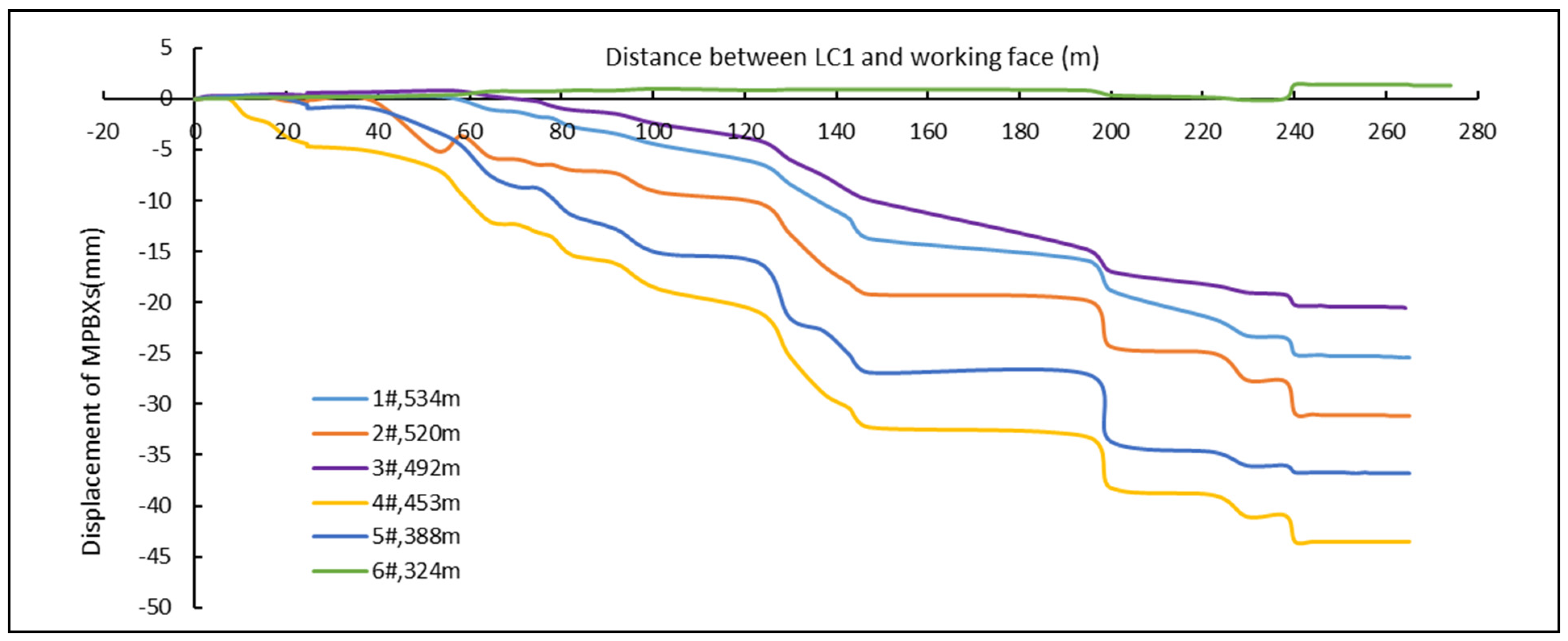
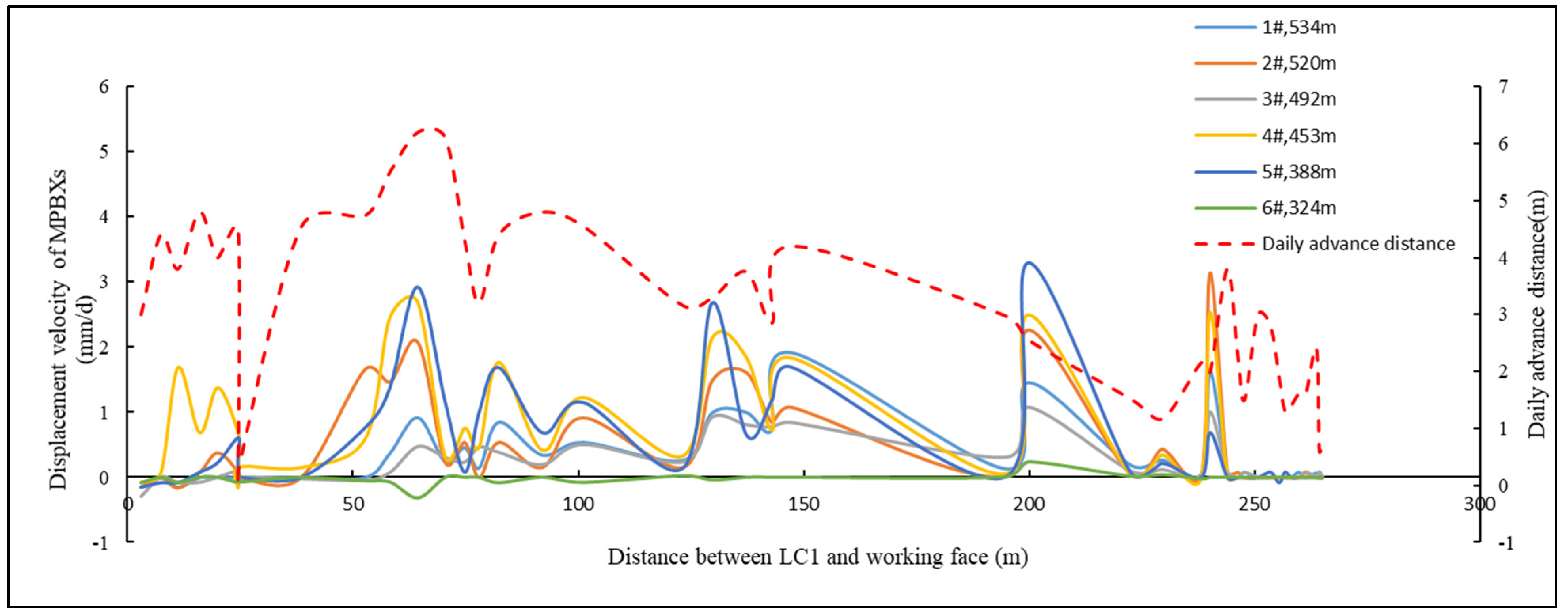
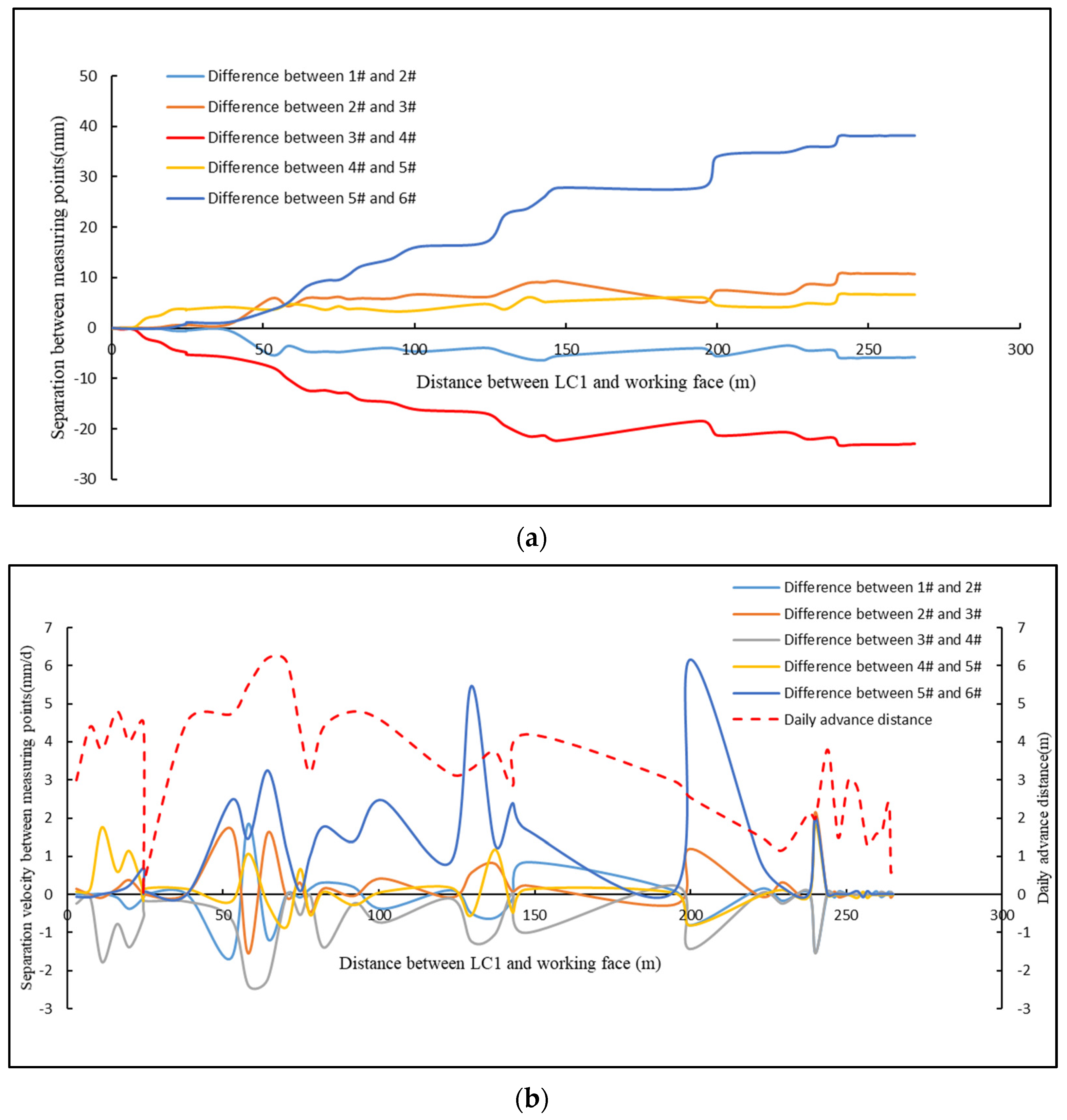
According to the displacement data obtained through the MPBXs inside the LC1 borehole, the largest displacement difference appears between the 5#MPBX at a depth of 388 m and the 6#MPBX at a depth of 324 m inside the LC1 borehole. This indicates that the subsidence deformation between the two corresponding overlying strata in the borehole is not synchronized. In other words, the largest development of the separation layer is located within the middle section of the Lo-ho Formation (between the depths of 388 m and 324 m).
(5)
Combined with the strain data of DOFS, displacement data obtained from MPBXs, and water level data, the height of the water-conducting fracture zone was mutually verified with the development of a separation layer in the overlying strata. The results obtained are in line with in situ monitoring data, which provides reliable guidance for the on-site control of hazards caused by separation seepers.

Author Contributions

Conceptualization and formal analysis, J.X.; writing—original draft preparation, J.X.; writing—review and editing, X.W.; validation, J.X. and X.W.; project administration, W.Q. All authors have read and agreed to the published version of the manuscript.

Funding

This research was funded by National Natural Science Foundation of China (52274097). The in situ monitoring program was under the auspices of a Research Program funded by Shaanxi Yonglong Energy Development and Construction Co. Ltd.

Institutional Review Board Statement

Not applicable.

Informed Consent Statement

Not applicable.

Data Availability Statement

The data presented in this study are available on request from the corresponding author.

Acknowledgments

We extend our sincere thanks to Yang Huang and other relevant mine engineers for their substantial support and help in field measurement.

Conflicts of Interest

The authors declare that this study received funding from Shaanxi Yonglong Energy Development and Construction Co. Ltd. The funder was not involved in the study design, collection, analysis, interpretation of data, the writing of this article or the decision to submit it for publication.

References

  1. Cao, D.T. Water inrush of hydrostatic pressure in separated layer and its control. Hydrogeol. Eng. Geol. 2013, 40, 9–12. [Google Scholar]
  2. Qiao, W.; Li, W.P.; Li, X.Q. Mechanism and prevention of “hydrostatic water inrush” of roof separation water in stope. J. Min. Safety. Eng. 2011, 28, 96–104. [Google Scholar]
  3. Xu, J.L.; Qian, M.G.; Jin, H.W. Study and application of bed separation distribution and development in the process of strata movement. Chin. J. Geotech. Eng. 2004, 24, 632–636. [Google Scholar]
  4. Ji, Y.D.; Cao, H.D.; Zhao, B.F. Mechanism and control of water inrush from separated roof layers in the jurassic coalfields. Mine Water Environ. 2021, 40, 357–365. [Google Scholar] [CrossRef]
  5. Li, H.J.; Chen, Q.T.; Shu, Z.Y.; Li, L.; Zhang, Y.C. On prevention and mechanism of bed separation water inrush for thick coal seams: A case study in China. Environ. Earth Sci. 2018, 77, 759. [Google Scholar] [CrossRef]
  6. Gandhe, A.; Venkateswarlu, V.; Gupta, R.N. Extraction of coal under a surface water body–a strata control investigation. Rock. Mech. Rock. Eng. 2005, 38, 399–410. [Google Scholar] [CrossRef]
  7. Holla, L. Ground movement due to longwall mining in high relief areas in New South Wales, Australia. Int. J. Rock. Mech. Min. Sci. 1997, 34, 775–787. [Google Scholar] [CrossRef]
  8. Wu, Q.; Liu, Y.; Zhou, W.; Li, B.; Zhao, B.; Liu, S.; Sun, W.; Zeng, Y. Evaluation of water inrush vulnerability from aquifers overlying coal seams in the Menkeqing Coal Mine, China. Mine Water Environ. 2015, 34, 258–269. [Google Scholar] [CrossRef]
  9. Heather, E.L.; Douglas, T.; Mark, K.L.; Habte, A. Effects of overburden characteristics on dynamic failure in underground coal mining. Int. J. Min. Sci. Tech. 2017, 27, 121–129. [Google Scholar]
  10. Ma, L.J.; Zhao, B.F.; Wang, H.; Gao, Y. Analysis of spatial differences in permeability based on sedimentary and structural features of the sandstone aquifer overlying coal seams in western China. Mine Water Environ. 2020, 39, 229–241. [Google Scholar] [CrossRef]
  11. He, J.H.; Li, W.P.; Qiao, W.; Yang, Z.; Wang, Q.Q. Risk assessment of water inrushes from bed separations in Cretaceous strata corresponding to different excavation lengths during mining in the Ordos Basin. Geomat. Nat. Haz. Risk. 2021, 12, 2300–2327. [Google Scholar] [CrossRef]
  12. Palchik, V. Formation of fractured zones in overburden due to longwall mining. Env. Geol. 2003, 44, 28–38. [Google Scholar] [CrossRef]
  13. Palchik, V. Localization of mining-induced horizontal fractures along rock layer interfaces in overburden: Field measurements and prediction. Env. Geol. 2005, 48, 68–80. [Google Scholar] [CrossRef]
  14. Gui, H.; Lin, M.; Song, X. Identification and application of roof bed separation (water) in coal mines. Mine Water Environ. 2019, 37, 376–384. [Google Scholar] [CrossRef]
  15. Sun, W.J.; Zhou, W.F.; Jiao, J. Hydrogeological Classification and Water Inrush Accidents in China’s Coal Mines. Mine Water Environ. 2016, 35, 214–220. [Google Scholar] [CrossRef]
  16. Xuan, D.Y.; Xu, J.L. Grout injection into bed separation to control surface subsidence during longwall mining under villages: Case study of Liudian coal mine. Nat. Haz. 2014, 73, 883–906. [Google Scholar] [CrossRef]
  17. Zhu, W.B.; Wang, X.Z.; Xu, J.L.; Liu, W.T. Study of mechanism of stope water inrush caused by water accumulation in overburden separation areas. Chin. J. Rock Mech. Eng. 2009, 28, 306–311. [Google Scholar]
  18. Abbas, M.; Ferri, P.H.; Mehdi, Y.N. Prediction of the height of destressed zone above the mined panel roof in longwall coal mining. Int. J. Coal Geol. 2012, 98, 62–72. [Google Scholar]
  19. Du, W.G.; Chai, J.; Zhang, D.D.; Lei, W.L. The study of water-resistant key strata stability detected by optic fiber sensing in shallow-buried coal seam. Int. J. Rock Mech. Min. Sci. 2021, 141, 104604. [Google Scholar] [CrossRef]
  20. Tan, Y.L.; Yu, F.H.; Chen, L. A new approach for predicting bedding separation of roof strata in underground coalmines. Int. J. Rock Mech. Min. Sci. 2013, 61, 183–188. [Google Scholar] [CrossRef]
  21. Sun, J.; Hu, Y.; Zhao, G.M. Relationship between water inrush from coal seam floors and main roof weighting. Int. J. Min. Sci. Tech. 2017, 27, 873–881. [Google Scholar] [CrossRef]
  22. Xu, J.L.; Zhu, W.B.; Wang, X.Z. New method to predict the height of fractured water-conducting zone by location of key strata. J. Chin. Coal Soc. 2012, 37, 762–769. [Google Scholar]
Figure 1. The working face plan and borehole design.
Applsci 14 06935 g001
Figure 2. The key strata distribution of LC1 borehole and No. 6 drainage hole based on logging data: (a) LC1 borehole; (b) No. 6 drainage hole.
Applsci 14 06935 g002
Figure 3. The installation scheme of MPBXs and DOFS inside LC1 borehole.
Applsci 14 06935 g003
Figure 4. The installation process of monitoring instruments: (a) installation process; (b) data acquisition system.
Applsci 14 06935 g004
Figure 5. The strain curves of DOFS: (a) the strain curves during 19 July–11 August 2022; (b) the strain curves during 14–16 August 2022.
Applsci 14 06935 g005
Figure 6. The strain curves of DOFS: (a) the strain curves during 17–24 August 2022; (b) the strain curves during 31 August–25 September 2022.
Applsci 14 06935 g006
Figure 7. MPBXs displacement curves inside the borehole.
Applsci 14 06935 g007
Figure 8. The changing curves of displacement velocity of MPBXs inside LC1 borehole.
Applsci 14 06935 g008
Figure 9. The breakpoint depth of DOFS in LC1 borehole.
Applsci 14 06935 g009
Figure 10. The correspondence between the strata movement inside LC1 borehole and the water level inside No. 6 drainage hole.
Applsci 14 06935 g010
Figure 11. The curves of the separation layer between the MPBXsinsideLC1 borehole and its velocity change: (a) the curves of the separation layer between MPBXs; (b) the velocity change curves of separation layers between MPBXs.
Applsci 14 06935 g011
Figure 12. The measured height of water-conducting fracture zone and the locations of the major separation.
Applsci 14 06935 g012
Disclaimer/Publisher’s Note: The statements, opinions and data contained in all publications are solely those of the individual author(s) and contributor(s) and not of MDPI and/or the editor(s). MDPI and/or the editor(s) disclaim responsibility for any injury to people or property resulting from any ideas, methods, instructions or products referred to in the content.

