Abstract
Aiming at the compliant end face gas film seal structure, based on the linearized Boltzmann equation, the Poiseuille flow coefficient is introduced, and the generalized Reynolds equation and the sealing performance parameter solution formula considering the boundary slip flow effect are established. Through Newton–Raphson iterative calculation, the degree of influence of the slip flow effect under different working conditions is analyzed, and the internal relationship between structural parameters and sealing performance is compared. The results show that the slip flow effect can have a large impact on the pressure distribution in the fluid field close to the low-pressure side. Due to the existence of the step phenomenon of boundary velocity, it is not conducive to increasing the gas film opening force and controlling the mass leakage rate, but it can play a positive role in reducing the viscous friction power consumption. In the case of a smaller sealing gas film thickness and lower medium pressure, the slip flow effect is significant, which will have a greater impact on the sealing performance, and at this time, the slip flow effect can not be ignored. In addition, the change in seal structure parameters will also have a large impact on the sealing performance. With an increase in the wave foil thickness, the compliant end face evolves towards the rigid end face, the fluid wedge effect is weakened, and the gas film opening force and mass leakage rate are reduced. The stiffness-to-leakage ratio shows a strong nonlinear decreasing trend with an increase in the wave foil chord length and pitch, which eventually tends to a stable value. The results of this paper provide a theoretical basis for the matching design of the structural parameters of compliant end-face gas film seals under different service conditions.
1. Introduction
As a new form of noncontact sealing, dry gas seals have been widely used in bioengineering, aerospace, and other fields [1,2]. In recent years, with the experimental research and development of high-altitude hypersonic flight aero-engine and the development of supercritical carbon dioxide power generation technology [3,4], the traditional rigid face dry gas seal is very easy to cause problems such as sealing vice deformation, wear, and abrasion, touching abrasion and so on, and even lead to instability and failure, which ultimately affects the normal work of the whole machine device in the rapid start–stop, abnormal perturbation, multi-variable rotational speeds, or skewed operation [5]. In response to the above problems, some scholars have proposed a new type of adaptive mechanical seal concept [6,7,8], which is more centrally designed as a compliant end face structure with wave foils and flat foils. The compliant end face deforms under the action of multiple loads, and the wedge-shaped gas film formed can greatly enhance the dynamic pressure effect and improve the opening force of the gas film. It can also spontaneously adjust the equilibrium relationship, effectively absorb vibration impact, and quickly adapt to the operating position so that the sealing system maintains a good sealing effect and stability.
As early as the beginning of the twenty-first century, scholars such as Heshmat and Agrawal [9,10] referred to the design concept of gas foil bearings, used elastic structure to replace the traditional rigid sealing end face and proposed a kind of compliant foil face gas seal structure. On this basis, Muson et al. [11] explored the change rule of sealing performance of compliant foil face gas seals under different working conditions. The results show that the flexible end face can provide excellent deformation resistance. Under high temperature and high-speed working conditions, it can effectively cope with a change in the sealing gas film thickness and show good sealing performance. Subsequently, Salehi [12] introduced the compliant foil face gas seal into the aero-engine performance test. NASA Glenn Research Center [13] successfully completed the compliant foil face gas seal test at 25000 rpm and 70 psiD pressure. It was found that the surface coating had a large effect on the sealing performance. Heshma Hooshang et al. [14,15] conducted high-temperature tests on compliant foil face gas seal and the results showed that the noncontact compliant foil gas seal has excellent sealing performance. Then, Heshma Hooshang et al. [16] used nonlinear coefficients to describe the turbulence effect and utilized the ultra-relaxation method to solve the coupled governing equations of flow pressure and film thickness to obtain the compressible fluid flow field under high-velocity conditions. In recent years, domestic scholars have gradually paid attention to compliant foil face gas seals and carried out related research. Chen Yuan et al. [17,18] analyzed the stable and dynamic performance of compliant foil face gas seals and studied the optimal design of the structure by establishing a theoretical model of gas–elastic coupling lubrication and solving the Reynolds equation by using the finite difference method. They analyzed the stability and dynamic performance of the compliant foil face gas seal and carried out research on the optimized design of the structure. The results of this study found that the compliant foil face gas seal has obvious advantages in terms of disturbance resistance compared with the traditional dry gas seal with a rigid end face. Subsequently, Chen Yuan et al. [19] analyzed the influence of blocking flow and inertia effect on the pressure field of sealing velocity occasions and explored the influence of operating conditions on sealing performance. Xu Jie et al. [20] pointed out in their study that the comprehensive performance of the seal can be effectively improved by introducing a compliant end face structure under high-speed and low-pressure conditions. Wang X et al. [21,22] designed a T-slot compliant foil gas film seal structure based on the existing floating plunger seal in order to meet the dynamic stability of an aero-engine and analyzed the effects of operating parameters on the rotor dynamic coefficient. Sun [23] and others proposed a new compliant seal structure. Based on the fluid-structure coupling analysis method, their three-dimensional flow field was simulated, and the effects of operating parameters and structural parameters on the steady-state characteristics were investigated.
Since the scale of the fluid lubrication gas film between the friction parts of the dry gas seal is micrometer scale, some scholars have carried out research on the thinning effect of the gas film seal. Bo Ruan [24] utilized the generalized gas film lubrication equation at an arbitrary Knudsen number derived using Fukui and Kaneko to analyze the flow field of a classical spiral groove dry gas seal. By studying the characteristic curves of the gas film pressure and gas film thickness, the results showed that the slip flow is most significant when the Knudsen number is greater than 0.05. On the basis of previous research, Huang Ping [25] fitted the equation for the flow coefficient of Poiseuille flow based on the movement of fluid in a wider flow channel, combined with the F-K (Fukui–Kaneko) model and the linear Boltzmann equation set. Ding Xuexing et al. [26,27] modified the generalized Reynolds equation and applied the PH linearization method to iteratively solve the key seal performance parameters under second-order nonlinear slip boundary conditions. Song Pengyun et al. [28,29] used the effective viscosity to characterize the slip flow and analyzed the degree of influence on the performance of the dry gas seal of the spiral groove under different working conditions by taking into account the real gas effect and the slip flow effect. Peng Xudong et al. [30,31] established a slip flow model considering the roughness of the seal end face and analyzed the interactive relationship between surface roughness and slip flow on the seal performance. Lu Junjie [32,33] compared the effects of the first-order velocity slip model, the second-order velocity slip model, and the F-K model on the new floating cylindrical microgroove gas film seal, respectively. It was found that the F-K model was more stable for calculations at high rotational speeds. Deng [34] et al. numerically solved the pressure distribution of a spiral groove dry gas seal using the finite difference method by integrating the slip flow effect and the real gas effect. The influence laws of the two effects on the startup characteristics of S-DGS under different structural parameters were discussed. The results show that the slip flow effect inhibits the opening ability of CO2 S-DGS, while the real gas effect enhances its opening ability. Ding [35] et al. used a high-precision eight-node finite difference method to calculate the gas film buoyancy by taking into account the coupling between the slip flow effect, surface microgrooves, and eccentricity. The influence of the slip flow effect on the gas sealing performance of spiral groove cylinders was discussed.
So far, although there have been studies describing the results on the flow field characteristics of cylindrical compliant foil gas film seals and the slip flow effect of rigid end-face dry gas seals, there are fewer studies on the slip flow effect of compliant foil face gas seals. In this paper, the linear Boltzmann equation is introduced into the process of seal performance analysis by taking the compliant foil face gas seal as the research object. Based on the Fukui–Kaneko slip flow model, a generalized Reynolds equation suitable for the solution of compliant foil face gas seal is established, which is coupled with the sealing gap control equation considering the deformation of wave and flat foils. The above equations are solved by coupling the center difference method and Newton–Raphson iteration method. The influence of the boundary slip flow effect on the seal performance parameters, such as gas film opening force, end face deformation, and the stiffness-to-leakage ratio of the compliant foil face gas seal, is analyzed. The influence of different foil structure parameters on the sealing performance is also analyzed with the consideration of the slip flow effect in order to provide a theoretical basis for the matching design of the structural parameters of compliant foil face gas seals under different service conditions.
2. Analytical Model
2.1. Physical Model
A compliant end face gas film seal structure comprising a dynamic ring and a static ring of the gas film seal. At least one sealing end face of the sealing ring is a compliant supporting surface. The sealing ring mainly comprises a sealing ring body, a top layer of flat foil, and a layer of supporting wave foil, as shown in Figure 1, which is a schematic diagram of the compliant end face gas film seal structure.
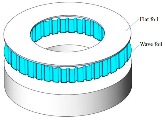
Figure 1.
Schematic diagram of compliant end face gas film seal structure.
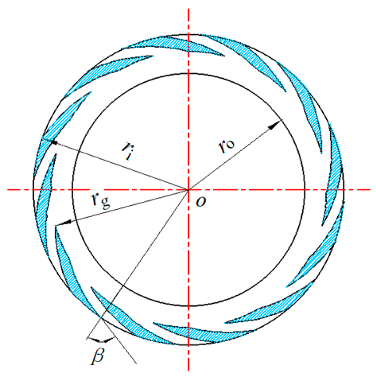
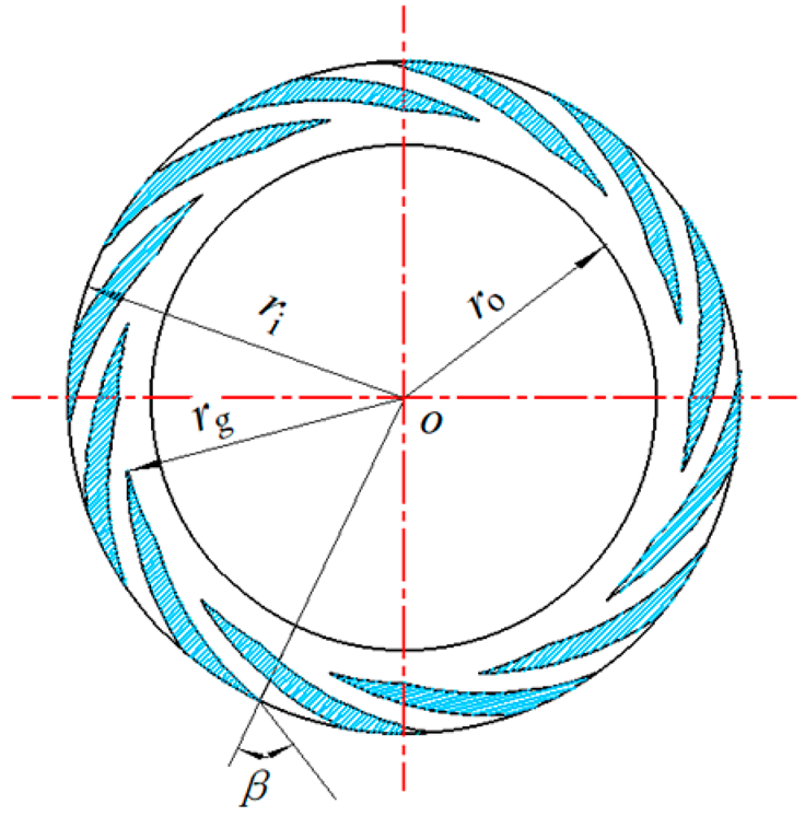
Figure 2 shows the working principle of a compliant end face seal. When the sealing medium from the sealing ring of the outer radius of the higher pressure side of the flow to the inner radius of the lower pressure side, the elastic end face in the viscous gas under the action of deformation, the friction between the formation of a certain degree of rigidity wedge-shaped gas film, to achieve the purpose of lubrication and sealing.
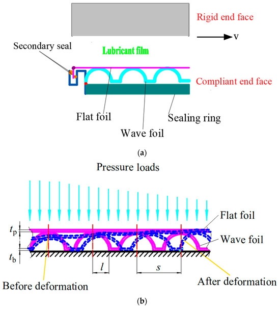
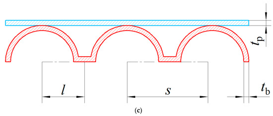
Figure 2.
Diagram of the compliant end face. (a) Working principle diagram; (b) Schematic diagram of end face deformation; (c) Schematic diagram of foil structure parameters.
In Figure 2b, tp is the thickness of the flat foil, mm; tb is the thickness of the wave foil, mm; l is half of the chord length, mm; and s is the pitch, mm.
2.2. Mathematical Model
2.2.1. Reynolds Equation without Slip Flow Effects
In order to simplify the description of the pressure solution model within the microscale flow field of the compliant end face gas film seal, this paper makes the following assumptions:
- (1)
- The fluid inside the gas film conforms to the isothermal ideal gas model;
- (2)
- The flow state is laminar;
- (3)
- The pressure of the gas film does not change in the direction of the gas film thickness;
- (4)
- The surface of the sealing vice is smooth, and the dynamic ring has a rigid end face;
- (5)
- Neglect the influence of volume force and inertia force;
- (6)
- There is no misalignment in the assembly.
The resulting dimensionless Reynolds equation, which does not account for boundary velocity slip effects, is obtained as:
The dimensionless parameter is defined as:
In the above formula, R is the dimensionless radius value; r is the radius position of any point, mm; ro is the outer radius of the sealing ring, mm; P is the dimensionless gas film pressure; p is the gas film pressure of any position, Pa; po is the outlet pressure, Pa; H is the dimensionless gas film thickness; h is the thickness of the gas film of any point position, μm; h0 is the minimum gas film thickness, μm; It is the thickness of the gas film when no deformation of the end face occurs, which is determined by controlling the distance between the sealing rings mainly through assembly; θ is the expansion angle; Λ is the compressibility coefficient of the gas medium; μ is the medium gas viscosity, Pa·s; ω is the rotational speed, r·min−1.
2.2.2. Reynolds Equation Considering Slip Flow Effects
According to Boltzmann’s analysis of the velocity slip effect at the wall boundary, it can be seen that there is a step in the slip velocity of the low-pressure gas flowing near the solid wall; the normal velocity gradient and the thermal creep effect are two important components of the boundary velocity slip [36,37]. However, in the compliant end face gas film sealing problem, the influence of the thermal creep effect is very small; therefore, the velocity slip equation for the compliant end face can be obtained. Fukui and Kaneko analyzed the ultra-thin gas lubrication problem by introducing Poiseuille flow coefficients and establishing the F-K slip flow model [38,39] based on the theory of the above study. The dimensionless modified Reynolds equation describing the boundary velocity slip flow effect considering thin gas action is obtained as:
where is the dimensionless Poiseuille flow coefficient, Qp is the Poiseuille flow coefficient, and Qcon is the continuous Poiseuille flow coefficient, which can be calculated by Equation (3) and Equation (4), respectively.
where is the inverse Knudsen number; Rg is the gas constant, J/(mol·K); T0 is the absolute temperature, K.
2.2.3. Control Equations for Gas Film Thickness
The thickness of the lubricating gas film between the friction parts of the foil seal depends, in addition to the initial minimum gas film thickness, on the deformation of the compliant end faces. The deformation of the seal end face is determined by the material and structural parameters of the flat and wave foils together. In this paper, the deformation of the compliant seal end face is described by the equivalent stiffness model [40]; therefore, the gas film thickness control equation is:
where po is the outlet pressure, Pa; h0 is the minimum gas film thickness, μm; α is the flexibility coefficient of the compliant end face;
When the sealing end face is not deformed, it is regarded as a rigid sealing end face; at this time,
When only the wave foil is deformed on the compliant sealing end face,
where kb is the unit stiffness coefficient of the wave foil, N/m2; s is the pitch, mm.
The unit stiffness coefficient of the wave foil can be calculated by the following equation [20,41]:
where Eb is the elastic modulus of wave foil, Pa; νb is the Poisson’s ratio of wave foil; tb is the thickness of the wave foil, mm; l is half of the chord length, mm.
When the compliant seal end face wave foil and flat foil are deformed, the comprehensive stiffness model of equivalent spring is used for calculation, i.e., the flat foil and wave foil are assumed to be linear springs with homogeneous stiffness, respectively and are arranged in parallel to obtain the overall stiffness model [20,41]:
where kp is the stiffness coefficient of flat foils, N/m3.
The stiffness coefficient of the flat foil can be obtained from the bending stiffness Dp of the flat foil [42].
where Dp is the bending stiffness of the flat foil, N·m; Ep is the elastic modulus of flat foil, Pa; νp is the Poisson’s ratio of flat foil; tp is the thickness of the flat foil, mm.
2.2.4. Boundary Conditions
The dimensionless inlet pressure boundary condition is
In the formula, Pi is the dimensionless inlet pressure; at this time, P = η, η is the ratio of inlet and outlet pressure.
The dimensionless outlet pressure boundary condition is
where Ri is the value of the dimensionless seal ring outer radius, and Ro is the dimensionless seal ring inner radius value.
Because of the symmetry and periodicity of the compliant end face structure of the gas film seal, in order to reduce the amount of computation, in this paper, 1/6 of the overall gas film is selected as the computational domain of a cycle, and the dimensionless pressure cycle boundary condition is:
where N is the number of cycles, one.
2.2.5. Seal Performance Parameters
The comprehensive performance of compliant end face gas film seals was evaluated by combining the gas film opening force, mass leakage rate, and viscous friction power consumption.
The dimensionless gas film opening force is:
The dimensionless mass leakage rate without considering slip flow effects
The dimensionless mass leakage rate due to slip flow effects is
The dimensionless mass leakage rate considering slip flow effects
The dimensionless viscous friction power consumption without considering slip flow effects
The dimensionless viscous friction power consumption considering slip flow effects
In Equation (19), λ is the mean free range of the dielectric gas, m; σv is the Tangential Momentum Coordination Coefficient (TMAC), and the value can be selected according to the surface properties of different engineering materials.
Dimensionless stiffness-to-drainage ratio without considering slip flow effects
Dimensionless stiffness-to-drainage ratio considering slip flow effects
where is the dimensionless average of the gas film thickness after the deformation of the compliant end face.
2.2.6. Differential Format of the Gas Film Pressure Control Equation
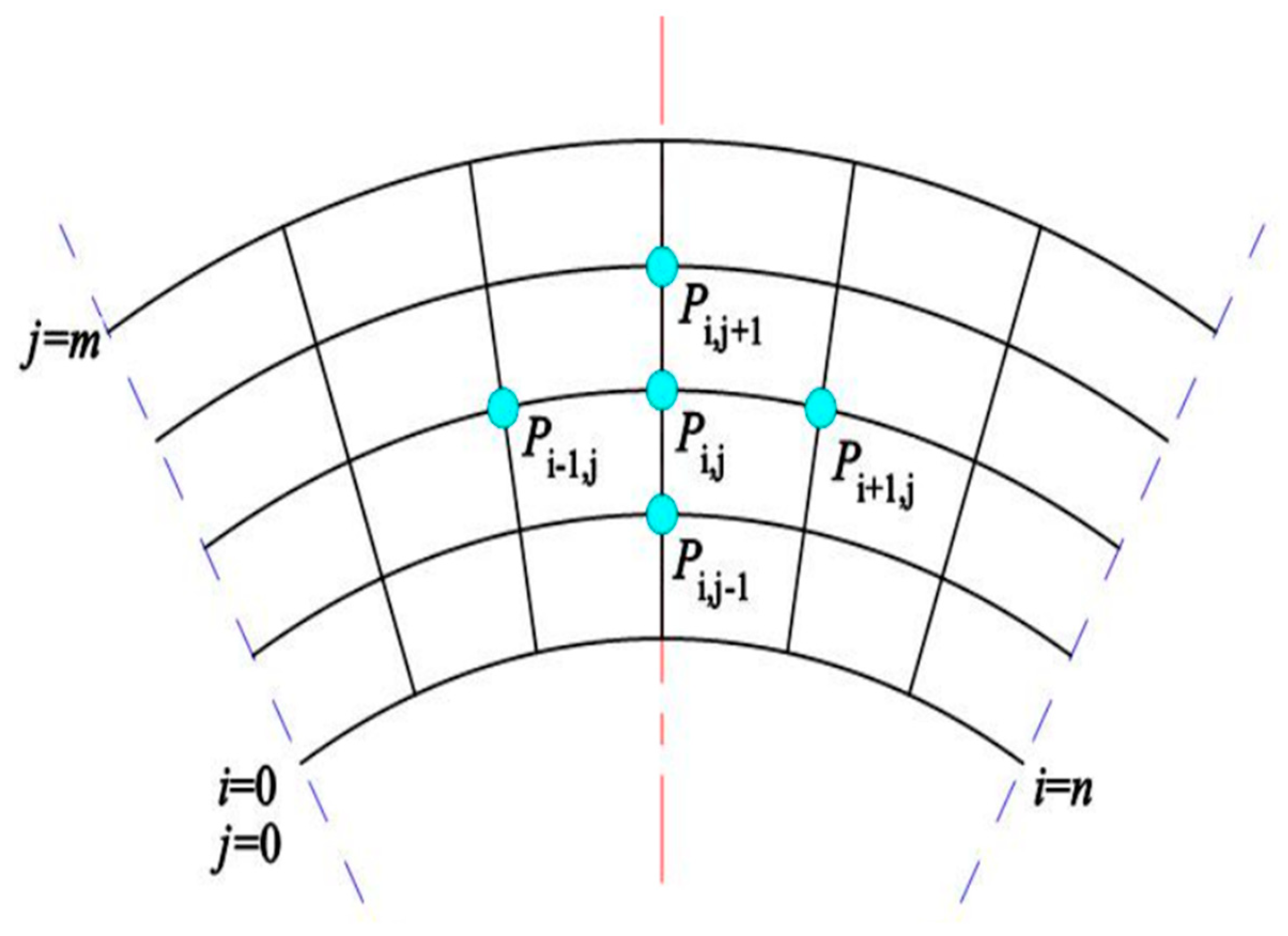
For the different forms of elastic foil dry gas seal separation, the computational domain is selected reasonably, and the mesh division in the circumferential direction and radial direction is carried out in one cycle. Figure 3 shows the schematic diagram of the mesh division of the computational domain.
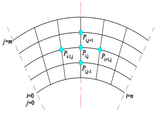
Figure 3.
Schematic diagram of computational domain meshing.
This yields the discrete format (22) of Equations (1) and (2)
where Ai,j, Bi,j, Ci,j, Di,j, Ei,j, Fi,j are the iterative coefficients, which are functions of the gas-film pressure and the gas-film thickness in the absence of slip-flow effects and functions of the gas-film pressure, the gas-film thickness, and the dimensionless Poiseuille flow coefficients in the case of considering the slip-flow effects, and δ is the difference in the dimensionless pressure field obtained from the two neighboring solutions.
2.2.7. Convergence Conditions and Iteration Error
Using the Newton–Raphson iterative method, the coupled solution of the gas-film pressure and gas-film thickness control equations is used to update the pressure distribution point by point, and the calculation results are considered to satisfy the accuracy when, and only when Equations (23) and (24) are satisfied at the same time.
3. Computational Validation
Table 1 shows the geometric and mechanical parameters of the sealing end face used in the numerical calculation, Table 2 shows the operating parameters of the compliant end face gas film seal, and Table 3 shows the performance parameters of the medium gas. Through the numerical method, different slip conditions are solved, and different structural parameters on the gas film end face seal characteristics are determined by the degree of influence.

Table 1.
Structural parameters and mechanical properties of compliant end face gas film seals.
Table 2.
Operating parameters for compliant end face gas film seals.
Table 3.
Gas performance parameters.
3.1. Irrelevance Verification of the Mesh
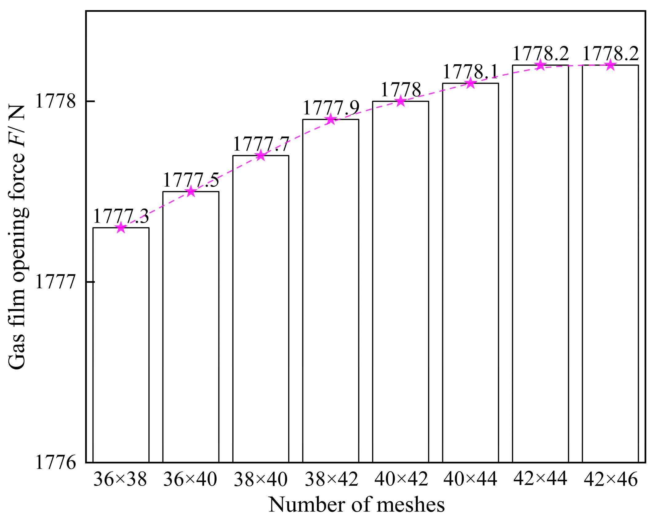
In order to ensure that the calculations with sufficient stability are completed in less time, a total of eight mesh node divisions, 36 × 38, 36 × 40, 38 × 40, 38 × 42, 40 × 42, 40 × 44, 42 × 44, and 42 × 46, are selected based on the size difference between the circumferential and radial directions in a calculation area. Using the geometrical and mechanical parameters of the sealing ring in Table 1, an average gas film thickness of 1.5 μm, a thickness of wave foil of 0.34 mm, a thickness of flat foil of 0.20 mm, a half-chord length of 2.2 mm, and a pitch of 4.6 mm were selected, and the operating parameters in Table 2 were set to calculate the opening force of the gas film under the consideration of the slip flow effect, which was used as a criterion for selecting the appropriate number of meshes.
As can be seen in Figure 4, the opening force of the gas film increases with an increase in the mesh density, but the numerical change is not obvious. When the number of meshes exceeds 40 × 42, the calculation result is basically kept at 1778 N. When the number of meshes is increased on this basis, the change in the calculation result is very small. Therefore, the 40 × 42 mesh is chosen as the best mesh for the calculation of this paper.

Figure 4.
Mesh-independent phase verification.
3.2. Validation of the Validity of the Computational Program
The parameters in the aforementioned table are applied to calculate the gas film opening force, and the calculation results of this paper are compared and analyzed with the literature so as to verify the correctness of the calculation theory and program writing in this paper. When the slip flow effect is not considered, the parameters of the literature [43] are selected for the calculation model, such as the validation model I in Table 4; when the slip flow effect is considered, the parameters of the literature [31] are selected for the calculation model, such as the validation model II in Table 4. The comparison results are shown in Figure 5.
Table 4.
Spiral groove dry gas seal construction parameters.
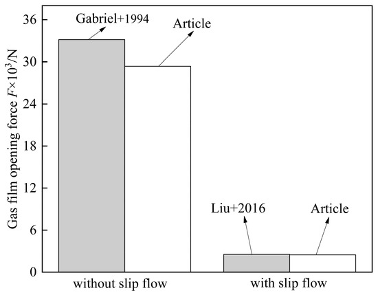
Figure 5.
Computational model validation [31,43].
As can be seen from Figure 5, the calculation results of this paper are all smaller than those in the comparable literature. Specifically, without considering the slip flow, the relative error between the calculated gas film opening force in this paper and the results of the Gabriel test [43] is 11.41%, which may be due to the assumptions of isothermal and neglecting inertial force in the calculation process of this paper, resulting in a certain error with these test data. In the case of considering the slip flow, the relative error between the calculation results of this paper and the results of the literature [31] is 3.27%. Taken together, the calculation errors in both cases are within the permissible range, indicating that the theoretical method and program writing in this paper have a certain degree of computational reliability.
4. Results and Discussion
4.1. Pressure Distribution and End Face Deformation
Based on the mathematical model established in the previous section, calculations are performed to obtain the deformation distribution of the compliant end face, as shown in Figure 6. The distribution of gas film pressure along the radius position is also obtained, as shown in Figure 7.
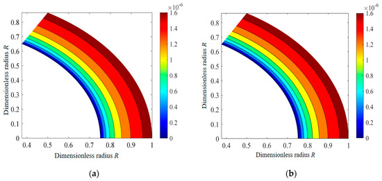
Figure 6.
Compliant end deformation distribution. (a) without slip flow; (b) with slip flow.

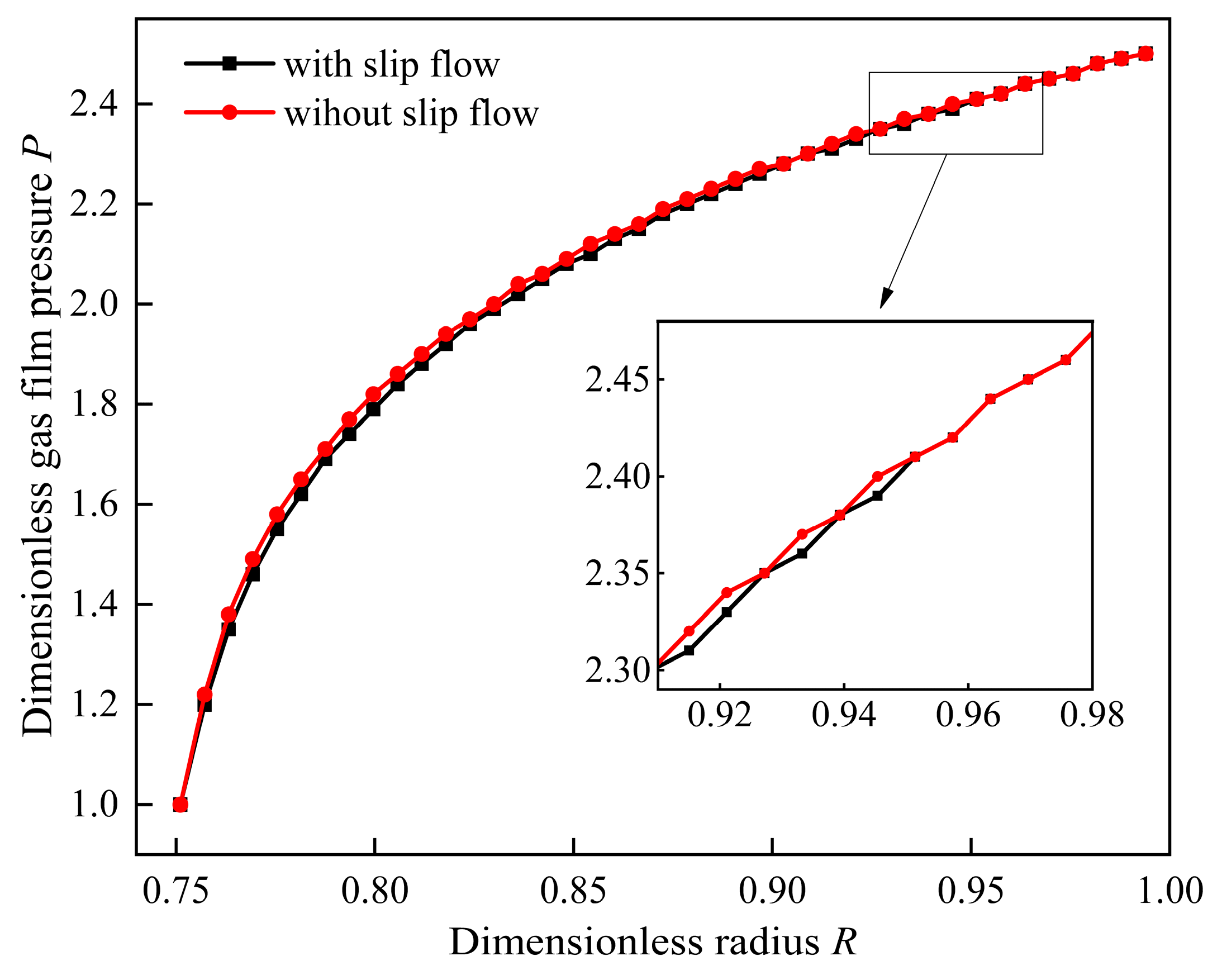
Figure 7.
Lubricated gas film pressure distribution.
By comparing Figure 6a,b, it can be found that the distribution of the deformation of the compliant end face is basically the same in both cases of considering the slip flow effect and not considering the slip flow effect, and the amount of deformation is basically the same at the same radius, and the area with the largest gradient of change is at the outer radius of the sealing ring, with a value of about 1.72 μm. At the inner radius of the sealing ring, since the outlet pressure of the medium is ambient atmospheric pressure, the sealing ring is basically not deformed, and the gas film thickness is the minimum gas film thickness h0. This trend makes the thickness of the gas film gradually decrease from the outer radius to the inner radius, thus forming a wedge-shaped gas film between the friction partners and effectively enhancing the sealing performance.
From the lubrication gas film pressure distribution diagram in Figure 7, it can be seen that the pressure change trend is basically the same in two cases, considering the slip flow effect and not considering the slip flow effect, which is shown as a gradual decline from the outer radius to the inner radius, and the first decline is slower, and then decline faster. This is due to the gas film pressure in addition to the sealing gap, but also with the inlet pressure, the inlet pressure directly affects the flow field pressure distribution. From the overall distribution of pressure variation with radius, the pressure without considering the slip flow effect is slightly larger than the pressure considering the slip flow effect. There is a maximum pressure difference when the radius value is 59.87 mm, which is close to the low-pressure side, and from this radius position, the closer to the inner radius and outer radius of the seal ring, the smaller the difference between the two. When the radius value is 74.39 mm, the calculation results considering the slip flow effect and not considering the slip flow effect are basically the same, and the slip flow effect basically does not play a role in this region. It can be seen that the slip flow effect is more significant in the low-pressure region of the lubricated gas film, which is manifested in the gradual weakening of the slip flow effect with an increase in the pressure inside the flow field.
4.2. Influence Law of Inlet and Outlet Pressure Ratio
Select the range of the inlet and outlet pressure ratio as 1.50~3.30, keep other parameters unchanged, and obtain the sealing characteristic parameters with the change rule of the inlet and outlet pressure ratio considering the slip flow effect and not considering the slip flow effect, as shown in Figure 8.
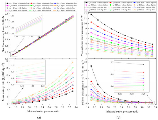
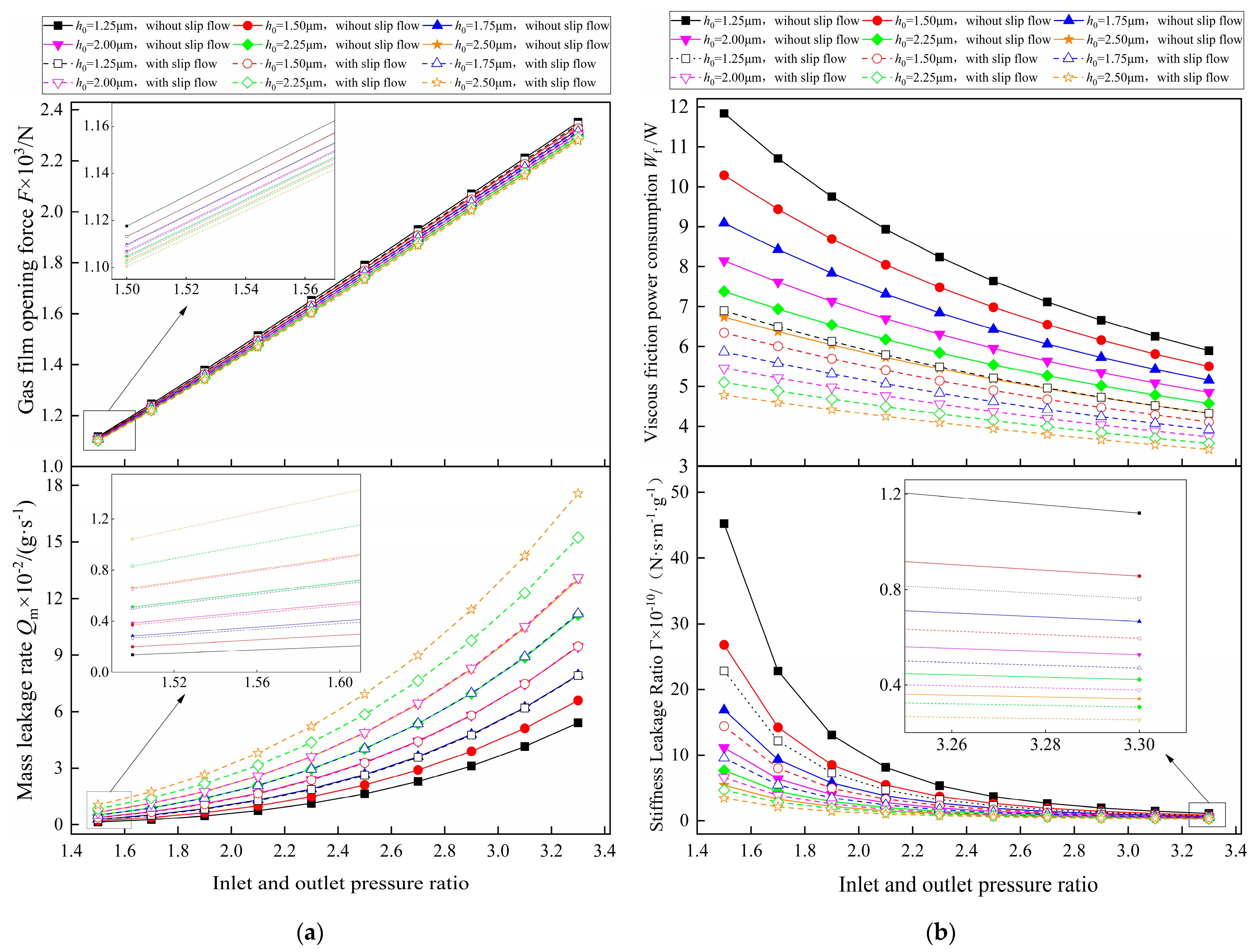
Figure 8.
Influence law of the inlet and outlet pressure ratio. (a) Gas film opening force and mass leakage rate; (b) Viscous friction power consumption and Stiffness Leakage Ratio.
Figure 8 shows the change rule of compliant end face gas film sealing characteristics under two velocity slip step cases. From Figure 8a, it can be seen that with an increase in the inlet and outlet pressure ratio, the gas film opening force increases significantly, showing a linear increasing trend. An increase in the inlet and outlet pressure ratio means that the pressure of the flow field between the end faces rises as a whole, so the effect on the opening force of the gas film is more significant.
The minimum gas film thickness value of 1.25 μm is selected for analysis, and when the inlet/outlet pressure ratio is 3.30, the opening force of the gas film considering the slip flow effect and not considering the slip flow effect are 2342.66 N and 2351.61 N, respectively, with a relative error of 0.38%; when the inlet/outlet pressure ratio is 1.50, the opening force of the gas film considering the slip flow effect and not considering the slip flow effect are 1113.17 N and 1117.69 N, with a relative error of 0.41%. The calculation results show that the role of the slip flow effect will gradually appear with a reduction in the ambient pressure, so when the compliant end face gas film seal is used in lower pressure conditions, the slip flow effect can not be ignored.
The inlet/outlet pressure ratio of 1.5 is selected for the analysis, and when the minimum gas film thickness is 1.25 μm, the opening force of the gas film considering the slip flow effect decreases by 4.53 N compared with that without the slip flow effect; when the minimum gas film thickness is 2.5 μm, the opening force of the gas film considering the slip flow effect decreases by 0.75 N compared with that without the slip flow effect. It is learned that the slip flow effect will gradually weaken with an increase in the gas film thickness, which is because the smaller the thickness of the gas film, the easier it is to gather the Knudsen layer at the sealing interface of the medium gas movement, resulting in the more obvious slip flow effect.
Observation of Figure 8a in the mass leakage rate with the law of change of the inlet and outlet pressure ratio can be seen; the mass leakage with an increase in the inlet and outlet pressure ratio shows an accelerated upward trend. As the mass leakage amount is expressed as the inner radius end surface medium in the outlet of the flow rate of the integral when the inlet and outlet pressure ratio increases, fluid under pressure from the outer radius to the inner radius of the direction of the accelerated flow, and thus the mass leakage rate increases. The presence of the slip flow effect increases the velocity distribution of the lubricating gas along the radial direction compared with the case where the slip flow effect is not considered. By solving the integral of the radial velocity distribution, it can be seen that the mass leakage rate considering the slip flow effect is slightly larger than the mass leakage rate without considering the slip flow effect, which is consistent with the results of reference [44].
According to the relationship curve between the inlet and outlet pressure ratio and viscous friction power consumption in Figure 8b, it can be seen that the slip flow effect can reduce the viscous friction power consumption. The smaller the ratio of the gas film thickness and inlet/outlet pressure, the larger the difference. The viscous friction power consumption has a maximum difference of 4.94 W when the minimum gas film thickness is 1.25 μm. Compared with the variation rule of the gas film opening force in Figure 8a, the boundary slip flow effect affects the viscous friction power consumption to a greater extent, which is due to the existence of the boundary slip flow effect, which makes the velocity gradient decrease, and the change in the shear stress caused by the Poiseuille flow plays a dominant role in the viscous friction power consumption.
By analyzing the parameter correlation between the import and export pressure ratio and the stiffness leakage ratio, it is found that with an increase in the import and export pressure ratio, the stiffness leakage ratio shows the law of change, which is completely opposite to the mass leakage rate. This is because the stiffness leakage ratio and gas film opening force, gas film thickness, and leakage have a relationship, although the compliant end face in the larger fluid pressure load will cause larger deformation, resulting in the sealing vice of the wedge-shaped gap between the increase in the thickness of the gas film, the leakage rate increases, changing the trend of the stiffness leakage ratio.
4.3. Influence Law of Structural Parameters
4.3.1. Influence Law of Wave Foil Thickness
The thickness of wave foil was chosen as 0.20~0.38 mm, the other parameters remained changed, and the change rule of sealing characteristic parameter with the thickness of wave foil considering the slip flow effect and not considering the slip flow effect was obtained, as shown in Figure 9.
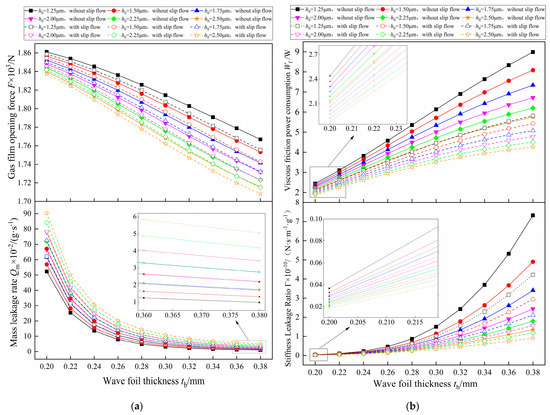
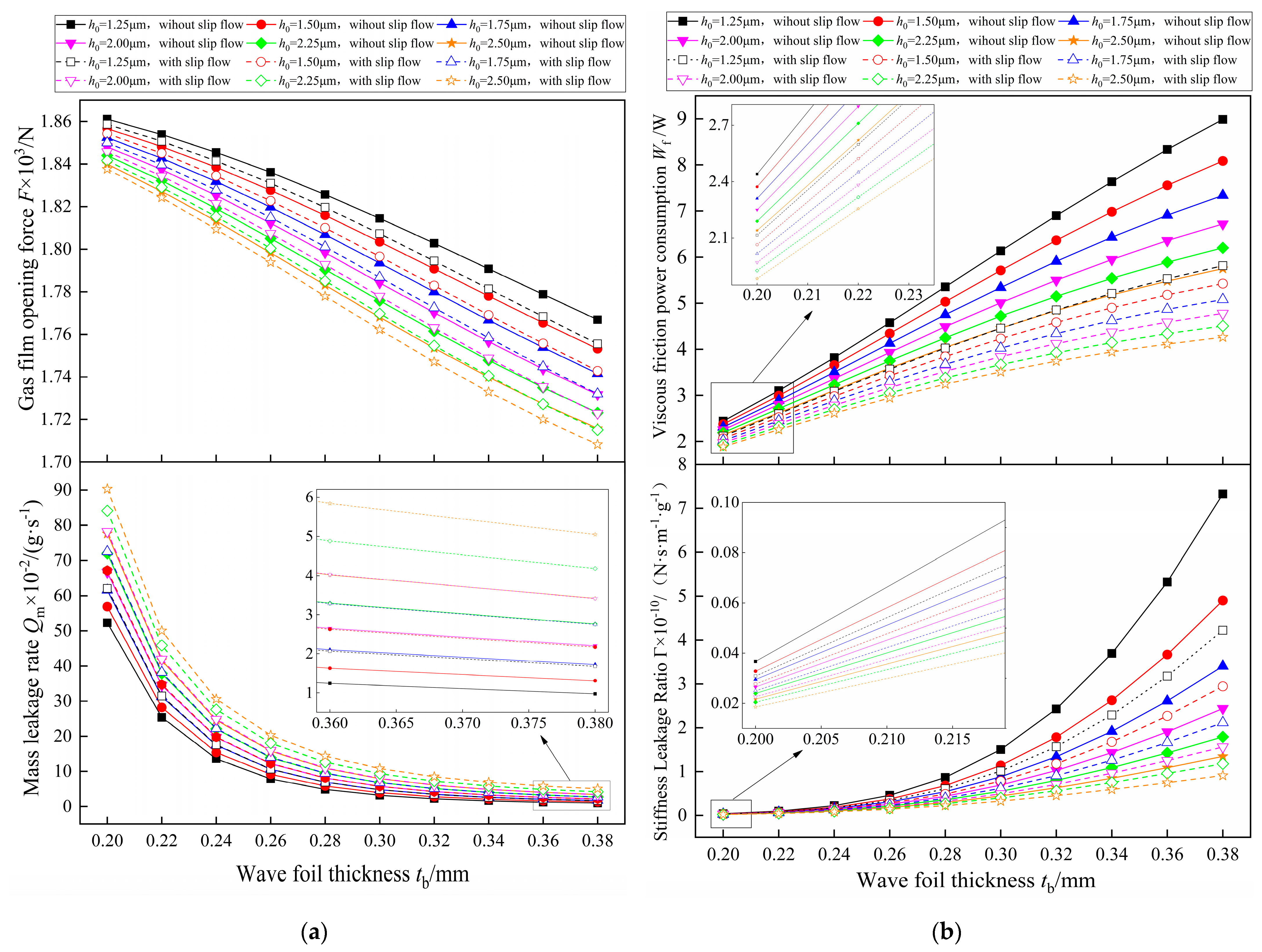
Figure 9.
Influence law of wave foil thickness. (a) Gas film opening force and mass leakage rate; (b) Viscous friction power consumption and Stiffness Leakage Ratio.
According to the change rule of gas film opening force and mass leakage rate with the wave foil thickness in Figure 9a, it can be seen that the gas film opening force decreases gradually with an increase in the wave foil thickness. In the minimum gas film thickness of 2.25 μm for analysis, when the wave foil thickness increases from 0.20 mm to 0.38 mm, the gas film opening force without slip flow effect decreases from 1844.00 N to 1723.19 N. This is due to an increase in the wave foil thickness, which strengthens the structure’s own support ability in the axial direction so that the compliant end face does not easily generate displacement in the axial direction, weakening the wedge-shaped effect, so the opening force of the gas film decreases. This change in its own properties caused by an increase in the thickness of the wave foil also implies a reduction in the sealing gap and a reduction in the leakage channels, and thus, it can be seen that the mass leakage rate decreases with an increase in the thickness of the wave foil, but the trend of this decrease is not infinite, but rather slowing down. It is shown that as the wave foil thickness tends to some larger value, the effect on the end face stiffness diminishes or does not even occur, i.e., the end face stiffening is approached.
The changing law of viscous friction power consumption and stiffness leakage ratio with the wave foil thickness is shown in Figure 9b. When the wave foil thickness increases, the end face stiffness increases, the deformation of the compliant end face decreases, and the end face distance decreases; thus, under the condition of the same gas film thickness, the velocity gradient of the gas film in the axial direction increases, and the relative motion between the fluid layer and the fluid layer is enhanced, and the viscous friction power consumption increases. Meanwhile, it can be observed that compared with the effect of the wave foil thickness on the viscous friction power consumption and the stiff leakage ratio, the effect of the gas film thickness on the stiff leakage ratio is more obvious. When the thickness of the gas film is smaller, the change in the stiffness leakage ratio is more obvious with an increase in the wave foil thickness. Therefore, the proper design of the wave foil thickness is crucial; the choice of the wave foil thickness not only depends on the impact of sealing performance but also on the processing method. A thinner or thicker wave foil is not easy to process, and molding is likely to rebound, so the structure of the dimensional accuracy is not enough.
4.3.2. Influence Law of Wave Foil Chord Length
The value range of the chord length was selected as 3.00~4.80 mm, the other parameters remained unchanged, and the change rule of the sealing characteristic parameters with the chord length considering the slip flow effect and not considering the slip flow effect was obtained, as shown in Figure 10.
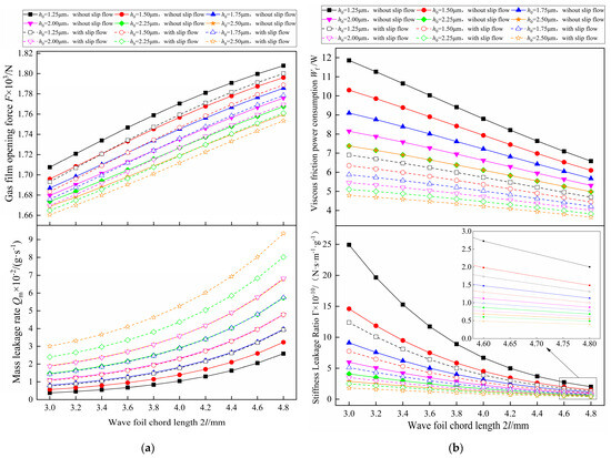
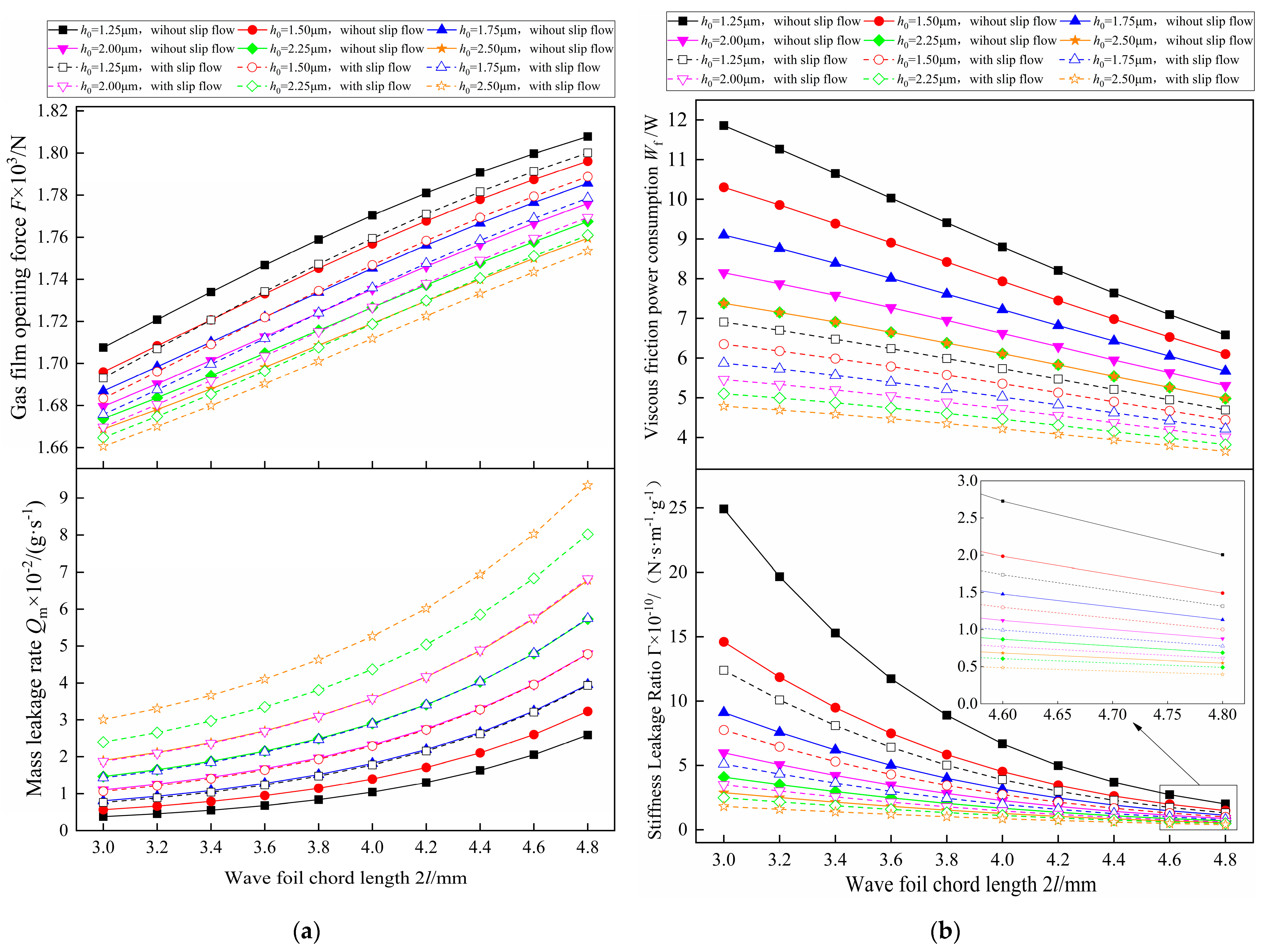
Figure 10.
Influence law of wave foil chord length. (a) Gas film opening force and mass leakage rate; (b) Viscous friction power consumption and Stiffness Leakage Ratio.
Both the gas film opening force and mass leakage rate increase with an increase in the wave foil chord length, and the viscous friction power consumption and stiff leakage ratio decrease with an increase in the wave foil chord length. The increasing and decreasing trends of the four sealing parameters are basically similar at different gas film thicknesses, regardless of whether the slip flow effect is considered or not. The effect of the wave foil chord length on the increase in the mass leakage rate is more pronounced than the effect of the wave foil chord length on the increase in gas film opening force, i.e., the mass leakage rate increases faster with an increase in the gas film thickness, a change that is not conducive for the seal structure to meet the performance requirements. Specifically, when the gas film thickness takes the maximum value of 2.5 μm, the mass leakage rate considering the slip flow effect grows by a factor of 0.91 compared with ignoring the slip flow effect.
Observing Figure 10b, it can be seen that the viscous friction power dissipation decreases with an increase in the chord length of the wave foil, and the smaller the minimum gas film thickness is, the more pronounced the decreasing trend of the viscous friction power dissipation. This is due to the fact that an increase in chord length leads to an increase in the end face spacing, which largely reduces the viscous drag force before the fluid layer, thus decreasing the viscous friction power dissipation. Without considering the slip flow effect, the viscous friction power consumption decreases by 44.48% for a minimum gas film thickness of 1.25 μm and 30.42% for a minimum gas film thickness of 2.50 μm when the chord length is increased from 3.00 mm to 4.80 mm. It can be seen that the smaller the gas film thickness, the more obvious the reduction in the viscous friction power consumption. In fact, compared with the stiff end face dry gas seal structure, the end face gas film seal with compliant foil structure plays an active role in reducing the viscous friction power consumption, reduces the friction heat generation between the end faces, and is more suitable for high-temperature environment service. Further observation reveals that the stiffness leakage ratio shows an exponentially distributed decreasing trend with increasing wave foil chord length, i.e., the decreasing magnitude of the stiffness leakage ratio gradually decreases. Under different gas film thicknesses, the stiffness leakage ratio tends to be a stable value with the chord length of the wave foil.
4.3.3. Influence Law of Wave Foil Pitch
The value range of the wave foil pitch was selected to be 1.50–2.50 mm, the other parameters remained unchanged, and the sealing characteristic parameters with the change rule of the wave foil pitch considering the slip flow effect and not considering the slip flow effect were obtained, as shown in Figure 11.

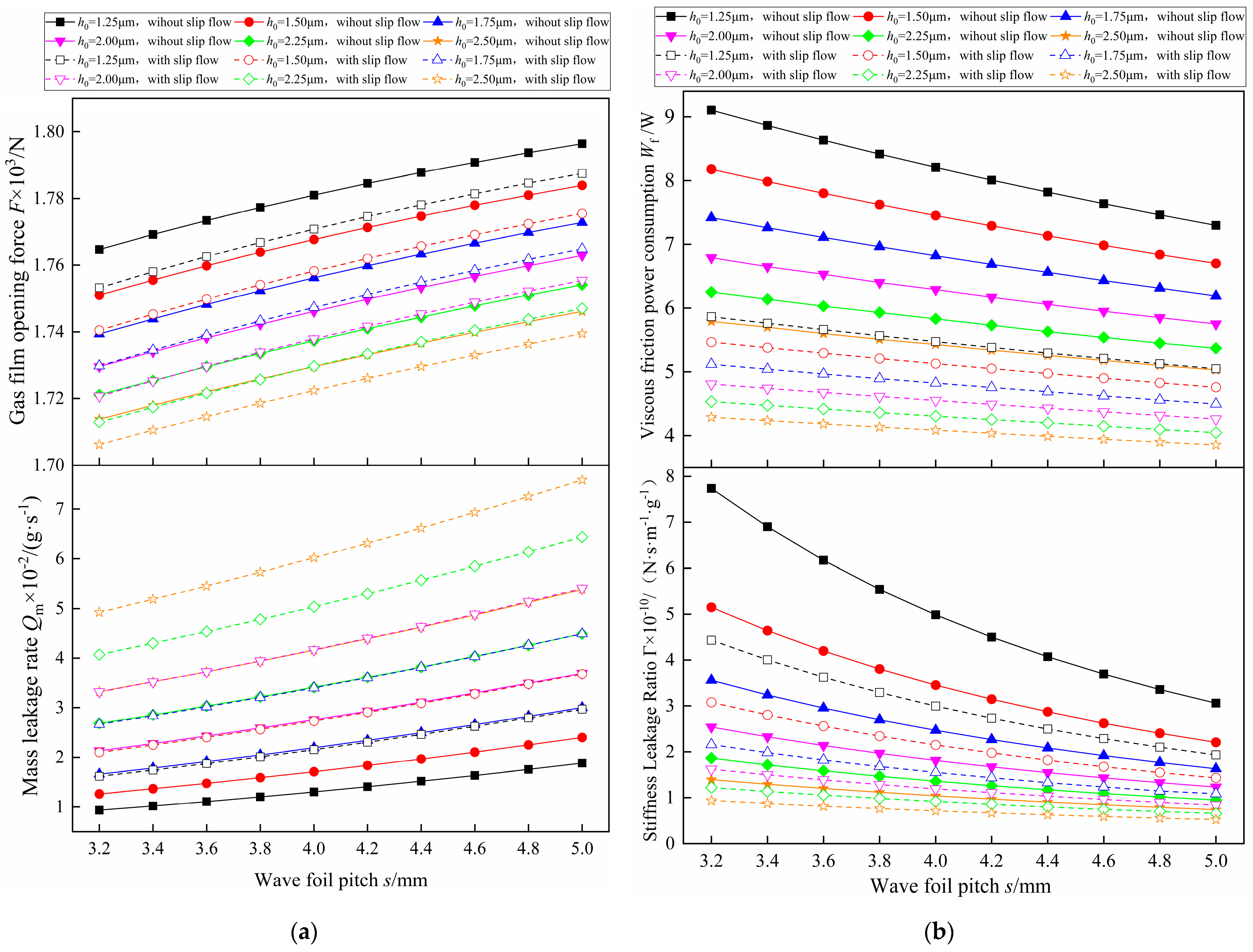
Figure 11.
Influence law of wave foil pitch. (a) Gas film opening force and mass leakage rate; (b) Viscous friction power consumption and Stiffness Leakage Ratio.
From Figure 11a, it can be seen that as the wave foil pitch increases, the gas film opening force then increases nearly linearly, and the gas film opening force without considering the slip flow effect is larger than the gas film opening force when considering the slip flow effect. Under the condition of the same minimum gas film thickness, the rising gradient is basically the same considering the slip flow effect and not considering the slip flow effect, which is due to an increase in the pitch, the wave foil is more prone to deformation in the axial direction, and the end face wedge effect is more prominent, which makes the gas film opening force increase. As the wave foil pitch increases over this range of variation, the mass leakage rate increases for the same minimum gas film thickness, both considering the slip flow effect and not considering the slip flow effect.
According to the relationship curves in Figure 11b, it can be seen that the viscous friction power consumption and stiffness leakage ratio show a decreasing trend as the pitch of the wave foil increases, and the slip flow effect exacerbates the decrease in the viscous friction power consumption. When the minimum gas film thickness is 1.25 μm, the viscous friction power consumption without considering the slip flow effect decreases by 1.81 W, a relative decrease of 24.78%, and the viscous friction power consumption with considering the slip flow effect decreases by 0.83 W, a relative decrease of 13.91%, with an increase in the wave foil pitch. This suggests that the presence of slip flow effects reduces the rate of reduction in the viscous friction power consumption. Through Figure 11b, it is found that the rate of decrease in the stiffness leakage ratio increases with an increase in the minimum gas film thickness, which shows that the setting of the minimum gas film thickness is more critical to the stiffness leakage ratio.
5. Conclusions
- (1)
- The slip flow effect is most significant at the radius of 59.87 mm near the low-pressure side, and from this position, the closer to the inner and outer radii of the seal ring, the weaker the influence of the slip flow effect.
- (2)
- The slip flow effect reduces the gas film opening force and viscous friction power consumption, increasing the mass leakage rate. As the thickness of the gas film increases and the ambient pressure decreases, the role of the slip flow effect will gradually come to the fore.
- (3)
- The opening force of the compliant end face gas film seal will be strengthened with an increase in the inlet and outlet pressure ratio, wave foil chord length, and pitch and weakened with an increase in the wave foil thickness, and the trend is nearly linear, in which the inlet and outlet pressure ratio has the greatest influence.
- (4)
- The thickness of wave foil increases, the stiffness of the compliant end face increases, and it is not easy to deform in the axial direction. The decreasing trend of the mass leakage and the increasing trend of the stiffness leakage ratio show strong nonlinear characteristics, indicating that the increasing thickness of wave foil makes the compliant end face evolve gradually to the stiff end face.
Author Contributions
Conceptualization, H.J. and S.Y.; methodology, H.J.; validation, H.J., S.Y. and X.D.; formal analysis, H.J.; investigation, H.J.; resources, H.J.; data curation, X.D.; writing—original draft preparation, H.J.; writing—review and editing, H.J.; visualization, H.J.; supervision, S.Y.; project administration, S.Y. and X.D.; funding acquisition, H.J. All authors have read and agreed to the published version of the manuscript.
Funding
This research was funded by the Gansu Basic Research Program—Outstanding Doctoral Student Project (granted no. 23JRRA782). The current research has been supported by National Key Research and Development Program (NKRDP) projects (granted 2020YFB2010001).
Institutional Review Board Statement
Not applicable.
Informed Consent Statement
Not applicable.
Data Availability Statement
Data will be made available on request.
Conflicts of Interest
The authors declare no conflicts of interest.
References
- Nelson, D.A. Development of a noncontacting mechanical seal for high performance turbocharger applications. J. Eng. Gas Turbines Power 2019, 141, 031008.1–031008.7. [Google Scholar] [CrossRef]
- Steinetz, B.M.; Hendricks, R.C. Engine seal technology requirements to meet NASA’s Advanced Subsonic Technology program goals. J. Propuls. Power 1996, 2, 786–793. [Google Scholar] [CrossRef]
- He, Q.; Huang, W.F.; Hu, G.Y.; Li, Y.J.; Liu, Y.; Wang, Y.M. Research status of the film-riding gas seal technologies in aeroengine. Aeroengine 2021, 47, 106–113. [Google Scholar]
- Li, Z.G.; Yuan, T.; Fang, Z.; Li, J. A review on dynamic sealing technology of supercritical carbon dioxide rotating machinery. Therm. Turb. 2019, 48, 166–174+191. [Google Scholar]
- Shang, H.; Chen, Y.; Li, X.L.; Wang, B.Q.; Li, Y.T.; Peng, X.D. Study on the influence of nonlinear effect on performance of dry gas seal underfilm thickness disturbance. CIESC J. 2021, 72, 2213–2222. [Google Scholar]
- Awtar, S.; Turnquist, N.A. Compliant Plate Seals for Turbomachinery. U.S. Patent 8382119 B2, 6 January 2010. [Google Scholar]
- Peng, X.D.; Chen, Y.; Jiang, J.B.; Li, J.Y. Air-Film Sealing Structure of Foil End Face with High-Pressure Deformation Cross-Scale Pore Texture. CN Patent 205978438U, 22 February 2017. [Google Scholar]
- Kang, Y.C.; Li, X.; Liu, M.H.; Wang, J. Cylindrical Gas Film Seal with Compliant Support of Bubbling Foil. CN Patent 112648378A, 13 April 2021. [Google Scholar]
- Heshmat, H. Compliant Foil Seal. U.S. Patent 6505837, 14 January 2003. [Google Scholar]
- Agrawal, L.G.; Patel, H.K.; Munson, H.J. Hydrodynamic Foil Face Seal. U.S. Patent 7261300, 28 August 2007. [Google Scholar]
- Munson, J.; Grant, D.; Agrawal, G. Foil face seal development. In Proceedings of the 37th Joint Propulsion Conference and Exhibit, Salt Lake City, UT, USA, 8–11 July 2001; p. 3483. [Google Scholar]
- Salehi, M.; Heshmat, H. Evaluation of Large Compliant Gas Foil Seals Under Engine Simulated Conditions. In Proceedings of the 38th AIAA/ASME/SAE/ASEE Joint Propulsion Conference & Exhibit, Indianapolis, IN, USA, 7–10 July 2002; p. 3792. [Google Scholar]
- Margare, P.; Delgado, I. Compliant foil seal investigations. In 2003 NASA Seal/Secondary Air System Workshop; NASA Glenn Research Center: Cleveland, OH, USA, 2004. [Google Scholar]
- Salehi, M.; Heshmat, H. Performance of a complaint foil seal in a small gas turbine engine simulator employing a hybrid foil/ball bearing support system. Tribol. Trans. 2001, 44, 458–464. [Google Scholar] [CrossRef]
- Heshmat, H.; Walton, J. Innovative High-temperature compliant surface foil face seal development. In Proceedings of the 44th AIAA/ASME/SAE/ASEE Joint Propulsion Conference & Exhibit, Hartford, CT, USA, 21–23 July 2008. [Google Scholar]
- Heshmat, H.; Salehi, M. Analysis of a compliant gas foil seal with turbulence effects. In Proceedings of the Joint Propulsion Conference & Exhibit, Salt Lake City, UT, USA, 8–11 July 2013. [Google Scholar]
- Chen, Y.; Chen, K.; Peng, X.D.; Wang, B.Q.; Li, X.L.; Jin, J. Research on the operation mechanism and performance of bump-type compliant foil face gas seal. J. Braz. Soc. Mech. Sci. Eng. 2022, 44, 325. [Google Scholar] [CrossRef]
- Chen, Y.; Chen, K.; Peng, X.D.; Li, Y.T.; Wang, B.Q.; Jin, J. Flow field and sealing performance analysis of compliant foil face gas seal. Adv. Mech. Eng. 2022, 14, 1–16. [Google Scholar] [CrossRef]
- Chen, Y.; Wang, Q.; Li, Y.; Li, X.; Wang, B.; Jin, J. Study on Sealing Characteristics of Compliant Foil Face Gas Seal under Typical Hypervelocity Gas Effects. Lubricants 2023, 11, 46. [Google Scholar] [CrossRef]
- Xu, J.; Yu, S.R.; Yan, R.Q.; Ding, X.X.; Wang, S.P.; Ding, J.J. Flow field analysis and sealing characteristics research of flexible end face gas film seals. China Mech. Eng. 2022, 33, 656–663. [Google Scholar]
- Wang, X.L.; Liu, M.H.; Kao-Walter, S.; Hu, X.P. Numerical evaluation of rotordynamic coefficients for compliant foil gas seal. Appl. Sci. 2020, 10, 3828. [Google Scholar] [CrossRef]
- Wang, X.L.; Liu, M.H. The Seal Performance of Compliant Foil Gas Seal Based on Multi-Scale Analysis. Processes 2022, 10, 1123. [Google Scholar] [CrossRef]
- Sun, J.; Liu, M.; Xu, Z.; Liao, T.; Hu, X.; Li, Y.; Wang, J. Coupled Fluid–Solid Numerical Simulation for Flow Field Characteristics and Supporting Performance of Flexible Support Cylindrical Gas Film Seal. Aerospace 2021, 8, 97. [Google Scholar] [CrossRef]
- Ruan, B. Finite element analysis of the spiral groove gas face seal at the slow speed and the low pressure conditions—Slip flow consideration. ASLE Trans. 2000, 43, 411–418. [Google Scholar] [CrossRef]
- Huang, P. Numerical Calculation Method of Lubrication; Higher Education Press: Beijing, China, 2012. [Google Scholar]
- Ding, X.X.; Pu, J.J.; Han, M.J.; Zhang, W.Z.; Yu, S.R. Calculation and analysis of gas film stiffness in the spiral groove gas seal based on the second order slip boundary. J. Mech. Eng. 2011, 47, 119–124. [Google Scholar] [CrossRef]
- Ding, X.X.; Su, H.; Pu, J.J.; Zhang, H.Z.; Zhang, W.Z. Calculation and analysis of leakage of apiral groove dry gas seal based on second-order slip boundary. Chin. J. Appl. Mech. 2013, 30, 49–53+145. [Google Scholar]
- Song, P.Y.; Zhang, S. An approximately analytical method of characteristics of spiral groove dry gas seals under slip flow conditions. J. Drain. Irrig. Mach. Eng. 2014, 32, 877–882. [Google Scholar]
- Song, P.Y.; Zhang, S.; Xu, H.J. Analysis of performance of spiral groove dry gas seal considered effects of both real gas and slip flow. CIESC J. 2016, 67, 1405–1415. [Google Scholar]
- Xu, J.; Peng, X.D.; Bai, S.X.; Li, J.Y.; Wang, Y.M. Effects of surface micro-scle and thermal viscosity on sealing performance of spiral-groove dry gas seal. CIESC J. 2013, 64, 3291–3300. [Google Scholar]
- Liu, M.J.; Peng, X.D.; Bai, S.X. Effects of random roughness on boundary slip of dry gas seals. Lubr. Eng. 2016, 41, 31–37. [Google Scholar]
- Lu, J.J. Study on Dynamic Lubrication Characteristics of a New Floating Cylindrical Groove Gas Film Seal. Ph.D. Thesis, Lanzhou University of Technology, Lanzhou, China, 2018. [Google Scholar]
- Lu, J.J.; Zhang, W.; Ma, H. Floating performance of cylindrical microgroove gas floating seal based on F-K slip flow model. CIESC J. 2021, 72, 4267–4278. [Google Scholar]
- Deng, Q.G.; Song, P.Y.; Xu, H.J.; Mao, W.Y.; Sun, X.J. Analysis on the startup characteristics of CO2 dry gas seal based on the F-K slip flow model at high pressure. Adv. Mech. Eng. 2023, 15, 16878132231163374. [Google Scholar] [CrossRef]
- Ding, J.H.; Yu, S.R.; Lu, J.J.; Ding, X.X. Control and analysis of floating ability of aeronautical cylindrical spiral groove gas seal based on F-K model. Adv. Mech. Eng. 2024, 16, 16878132241236591. [Google Scholar] [CrossRef]
- Wu, Q.F.; Chen, W.F.; Huang, L.; Shi, Y.Z. Rarefied Gas Dynamics; National University of Defense Technology Press: Beijing, China, 2004. [Google Scholar]
- Canadax, G.E.; Boscok, E. Micro Flow-Basics and Simulation; Chemical Industry Press: Beijing, China, 2006. [Google Scholar]
- Fukui, S.; Kaneko, R. A Database for Interpolation of Poiseuille Flow Rates for High Knudsen Number Lubrication Problems. ASME J. Tribol. 1990, 112, 78–83. [Google Scholar] [CrossRef]
- Fukui, S.; Kaneko, R. Analysis of ultra-thin gas film lubrication based on linearized Boltzmann equation: First report—Derivation of a generalized lubrication equation including thermal creep flow. Trans. ASME J. Tribol. 1988, 110, 253. [Google Scholar] [CrossRef]
- Yan, J.J.; Liu, Z.S.; Wang, Z. Performance Aanalysis of Hydrodynamic GasFoil Thrust Bearing Based on Newton-Raphson It-erative Method. Turbine Technol. 2017, 59, 116–120. [Google Scholar]
- Zhao, X.Y. Theoretical Analysis and Experimental Investigation on the Performance of a NovelGas Foil Bearing with High Structural Damping and Its Rotordynamic Response. Ph.D. Thesis, Hunan University, Changsha, China, 2017. [Google Scholar]
- Xia, X.P. Analysis of the Flow Field and Influence of Top Foil Deformation to Performance of Gas Foil Bearings; Graduate School of Chinese Academy of Sciences (Institute of Engineering Thermophysics): Beijing, China, 2011. [Google Scholar]
- Gabriel, R.P. Fundamentals of spiral groove non-contacting face seals. Lubr. Eng. 1994, 50, 215–224. [Google Scholar]
- Wang, B. Numerical analysis of a spiral-groove dry-gas seal considering micro-scale effects. Chin. J. Mech. Eng. 2011, 24, 146–153. [Google Scholar] [CrossRef]


Disclaimer/Publisher’s Note: The statements, opinions and data contained in all publications are solely those of the individual author(s) and contributor(s) and not of MDPI and/or the editor(s). MDPI and/or the editor(s) disclaim responsibility for any injury to people or property resulting from any ideas, methods, instructions or products referred to in the content. |
© 2024 by the authors. Licensee MDPI, Basel, Switzerland. This article is an open access article distributed under the terms and conditions of the Creative Commons Attribution (CC BY) license (https://creativecommons.org/licenses/by/4.0/).