
Modern Dimensional Analysis Model Laws Used to Model Additive Manufacturing Processes


 ,
,  ,
,  ,
,
Abstract
:Featured Application
Abstract
1. Introduction
2. The Most Used Dimensional Methods
- the Buckingham’s theorem;
- the partial differential equations applied to fundamental differential relations of the analyzed phenomenon, when the initial variables, by suitable grouping, offer these dimensionless quantities;
- the complete, but at the same time the simplest, equation(s) which describe the phenomena, which will be transformed into dimensionless forms, finally offering the desired groups.
- the protocol in obtaining the desired set of groups is rather chaotic, arbitrarily and strongly depending on the ingenuity and experience of the involved specialist;
- for the involved specialist, solid knowledge in the field of the analyzed phenomenon and higher mathematics are required as well;
- only rarely (occasionally) can the complete ML be obtained, mainly due to the fact that there are only a limited number of the involved mathematical relations related to the phenomena;
- for common engineers or specialists, involved in prototype–model correlation analysis, CDA does not represent an easy approach.
- the involved specialist, instead of being a thorough connoisseur in the phenomenon as well as in higher mathematics, only has to identify the set of the involved variables, together with their dimensions, which have (or can present) a certain extent influence on the analyzed phenomena;
- it has a unitary, simple, and user-friendly protocol, which assures at once to automatically eliminate all insignificant/irrelevant variables;
- in all cases, MDA assures obtaining the complete set of the dimensionless variables, as well as the complete ML; this is practically impossible using the aforementioned methods, excepting some particular cases;
- this ML is very flexible, suitable for several particular cases, corresponding to simplified approaches of the phenomena;
- by a priori setting of the directly related variables to the conceived experimental investigations on model, hereafter named independent variables, MDA assures additional flexibility, which represents a significant advantage, non-existent in all the methods mentioned above; their a priori choice is possible both for the prototype and model;
- this set (of the independent variables) assures defining the most suitable model, which will offer for the involved model the most simple, lower-cost testing conditions, safety, as well as repeatable experimental investigations;
- the rest of the variables, hereafter named dependent variables, can be chosen priori only for the prototype; their magnitudes for the model are strictly obtained by applying a given (suitable) element of the ML;
- among the dependent variables there are also a small number of prototype variables, whose magnitude cannot be obtained more easily (with low cost or accessible experimental measurements) and whose determination is actually the purpose of this dimensional analysis; thus, these aforementioned prototype’s variables are obtained by applying the ML;
- furthermore, MDA removes the restriction of the geometric similarity of the model with the prototype, e.g., the shape of the cross-sections can be different at the model from the prototype; in this case, instead of choosing the cross-sectional dimensions as independent variables, one will substitute them by the second order moment of inertia of the cross-section;
- if the material is considered as an independent variable, chosen by means of Young modules, then one can accept different materials for the model, relative to the prototype;
- in the case of choosing the flexural stiffness (rigidity) instead of the cross-sectional dimensions, than neither the shape of the cross-section, nor the type of material must be identical in the prototype and model; the single condition remaining is that their scale factor must remain the same (to be constant), where this scale factor is defined as the ratio of the flexural stiffnesses, that is, , with the aforementioned indexing (2 for model, and 1 for prototype).
3. Most Used Dimensional Methods in Additive Manufacturing
4. Modern Dimensional Analysis Involved in Additive Manufacturing
- all the variables, together with their dimensions, that can influence the phenomena to a certain extent are selected;
- by taking into consideration the experimental requirement of as simple, repeatable, and less-expensive model as possible, the independent variables are selected; their dimensional exponents constitute the so-called Matrix A, a non-singular square one, i.e., ;
- the rest of the variables (the dependent ones) constitute Matrix B, without any requirement; from matrix B, a number of variables can be neglected at any time in order to model a simpler case;
- completing these matrices with matrix and an adequate unit matrix results in the so-called Dimensional Set (Table 1);
- Each line , of matrices C–D, will offer by a simple calculus one element of the requested complete ML, corresponding to one of the dimensionless variable.

- One can observe that, for the requested ML, there are many complicated and sophisticated groupings of elements from the involved differential equations in order to obtain the required dimensionless variables and no requirement for deep connoisseurs in the analyzed phenomena;
- it must be emphasized that these elements of the ML do not represent actual physical laws, but only correlations between the variables related to the prototype and the model, which must be respected in everything;
- the unique protocol automatically eliminates the irrelevant variables (their columns in matrix C will contain only zeros);
- based on experimental investigations (strictly on the attached model), it became possible to obtain the foresighted (anticipated) parameters for the prototype by means of the deduced ML;
- the deduced ML also represents a very flexible set of information, because one can ignore (eliminate) some elements, if we are looking for a simplified model–prototype correlation, without any changing in the expressions of the other elements of the ML; this also constitutes another distinctive advantage of the MDA, which is not proper to any of the above-mentioned dimensional methods;
- In addition, depending on the concrete conditions available, the strategy of the experimental investigations can be adapted to the new conditions, by reseating and reconsidering the sets of independent variables, relative to the dependent ones;
- The deduced ML for a given type of structural element (e.g., straight bars) can be extended without any difficulties to the real structure, taking into consideration their homologous points of time as well as loads for the demanded variable;
- –
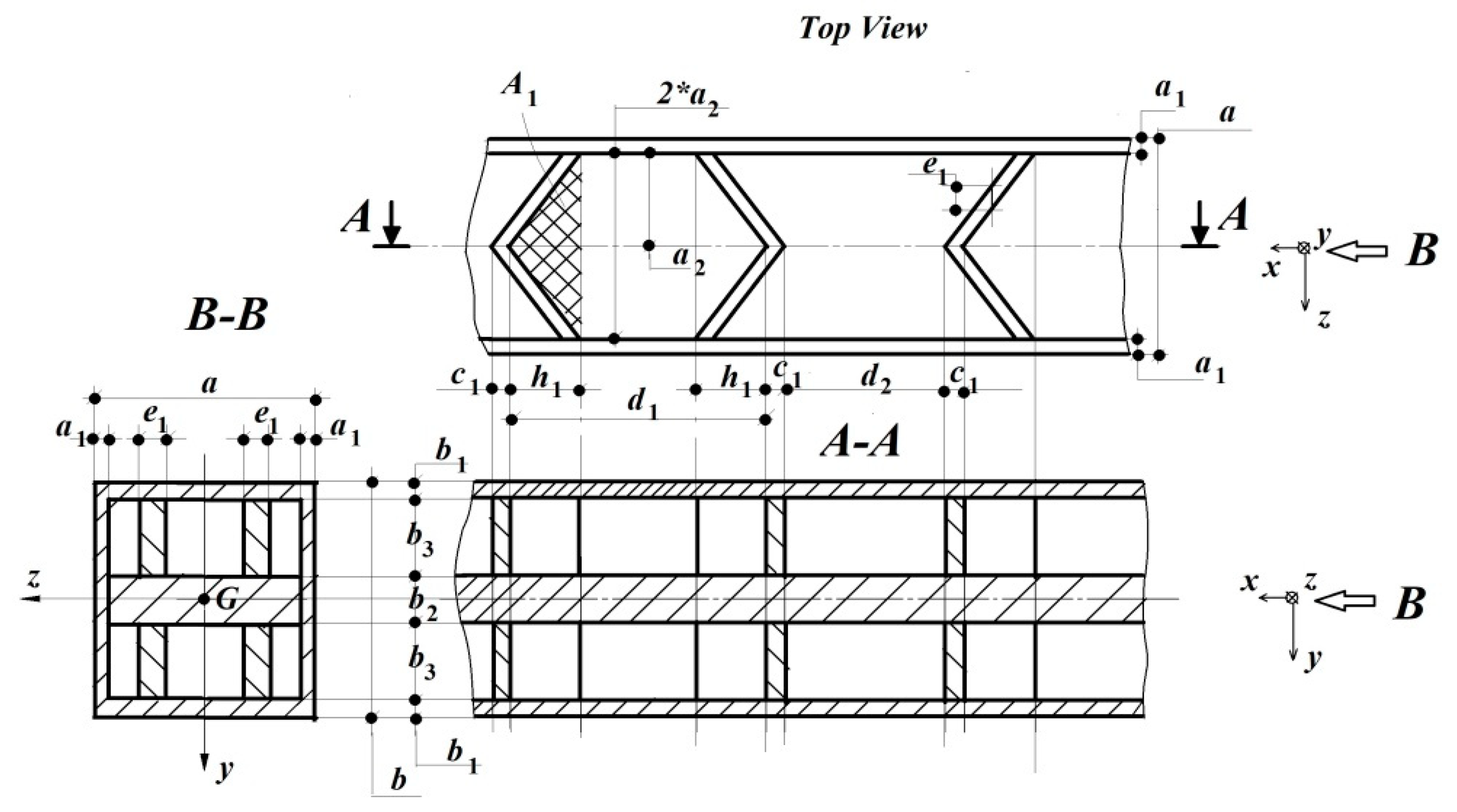
- the beam’s dimensions , as well as the area defined by the ribs;
- –
- the applied force;
- –
- the Young modulus, which for PLA is ;
- –
- the useful volume of the beam, that is related to the filling degree.
- –
- the second order moment of inertia, instead of the given cross-sectional dimensions;
- –
- by fusion of the initial variables, a more flexible model can be obtained, e.g., instead of E and Iz, one can use their product , that is, the stiffness module; if necessary, the density or specific gravity can also be involved.
- On the other hand, in order to increase the number of dimensions and thus reduce the number of the dimensionless variables, the so-called dimension splitting can be applied, e.g., instead of length “m”, its components along (mx, my, and mz) can be used.
- By choosing and as independent variables, there is evidence that that the remaining parameters , can be divided into others, such as ; ; without affecting the final ML;
- In addition, for a correct merging of the initial sizes in , they (that is, and ) can no longer appear in other elements, as they are omitted in ;
- When we abstract from these internal dimensions, we obtain the solid cross-sectional beam; in this sense, we simply neglect these internal dimensions together with their corresponding elements of the deduced ML.
| B | A | ||||||||
|---|---|---|---|---|---|---|---|---|---|
| v | a* | b* | c* | A1 | F | Vutil | L | E*Iz | |
| m | 1 | 1 | 1 | 1 | 2 | 0 | 3 | 1 | 2 |
| N | 0 | 0 | 0 | 0 | 0 | 1 | 0 | 0 | 1 |
| π1 | 1 | 0 | 0 | 0 | 0 | 0 | 0 | −1 | 0 |
| π2 | 0 | 1 | 0 | 0 | 0 | 0 | 0 | −1 | 0 |
| π3 | 0 | 0 | 1 | 0 | 0 | 0 | 0 | −1 | 0 |
| π4 | 0 | 0 | 0 | 1 | 0 | 0 | 0 | −1 | 0 |
| π5 | 0 | 0 | 0 | 0 | 1 | 0 | 0 | −2 | 0 |
| π6 | 0 | 0 | 0 | 0 | 0 | 1 | 0 | 2 | −1 |
| π7 | 0 | 0 | 0 | 0 | 0 | 0 | 1 | −3 | 0 |
5. Conclusions
- The elaborated MLs, validated by meticulous experimental investigations, offer several useful correlations between the prototype’s (i.e., the final product) and the assigned reduced scale model’s geometrical parameters and mechanical behaviors;
- by performing experimental investigations on the assigned model, applying the ML, it was possible to predict the real-scale prototype’s response to the applied mechanical or thermal loading;
- the ML also assures the stiffness optimization of the final product by means of changing the geometry and orientation of the involved ribs, the filling percentage, and the usable material.
- one other kind of stiffness optimization is the well-known honeycomb cross-section, which can also be more easily modelled with the deduced MLs by substituting the involved new length variables instead of the used ones;
- all the above-analyzed MLs can be successfully applied both for solid cross-sectional beams manufactured from PLA, and metallic ones; metal beams have simpler and more flexible MLs, as verified in advance by the authors;
- The authors’ future goals consist of extending the research area on the optimization of mold-forms used in plastic material components fabrication, mainly for in demand spare parts.
Author Contributions
Funding
Institutional Review Board Statement
Informed Consent Statement
Data Availability Statement
Conflicts of Interest
References
- Anderson, D.M. Design for Manufacturability & Concurrent Engineering: How to Design for Low Cost, Design in High Quality, Design for Lean Manufacture, and Design Quickly for Fast Production; CIM Press: Dundalk, Ireland, 2004. [Google Scholar]
- Aw, J.; Parikh, N.; Zhang, X.; Moore, J.; Geubelle, P.; Sottos, N. Additive manufacturing of thermosetting polymers using frontal polymerization. Abstracts of Papers of the American Chemical Society. In Proceedings of the 257th National Meeting of the American-Chemical-Society (ACS), Orlando, FL, USA, 31 March–4 April 2019; Volume 257, p. 91. [Google Scholar]
- Boyard, N.; Rivette, M.; Christmann, O.; Richir, S. A design methodology for parts using additive manufacturing. In High Value Manufacturing: Advanced Research in Virtual and Rapid Prototyping: Proceedings of the 6th International Conference on Advanced Research in Virtual and Rapid Prototyping, Leiria, Portugal, 1–5 October 2013; CRC Press: Leiden, The Netherlands, 2013. [Google Scholar]
- Butt, J.; Bhaskar, R. Investigating the Effects of Annealing on the Mechanical Properties of FFF-Printed Thermoplastics. J. Manuf. Mater. Process. 2020, 4, 38. [Google Scholar] [CrossRef]
- Dinar, M.; Rosen, D.W. A Design for Additive Manufacturing Ontology. In Proceedings of the ASME 2016 International Design Engineering Technical Conferences and Computers and Information in Engineering Conference, Charlotte, NC, USA, 21–24 August 2016. [Google Scholar]
- Du Plessis, A.; Yadroitsev, I.; Yadroitsava, I.; Le Roux, S.G. X-ray microcomputed tomography in additive manufacturing: A review of the current technology and applications. 3D Print. Addit. Manuf. 2018, 5, 227–247. [Google Scholar] [CrossRef]
- Gibson, I.; Rosen, D.W.; Stucker, B. Additive Manufacturing Technologies; Springer: Cham, Switzerland, 2010; pp. 17–40. [Google Scholar]
- Hatchuel, A.; Weil, B. A new approach of innovative Design: An introduction to CK theory. In Proceedings of the ICED 03, the 14th International Conference on Engineering Design, Stockholm, Sweden, 19–21 August 2003. [Google Scholar]
- Hirtz, J.; Stone, R.B.; Mcadams, D.A.; Szykman, S.; Wood, K.L. A functional basis for engineering design: Reconciling and evolving previous efforts. Res. Eng. Des. 2002, 13, 65–82. [Google Scholar] [CrossRef]
- Jasiuk, I.; Abueidda, D.W.; Kozuch, C.; Pang, S.Y.; Su, F.Y.; McKittrick, J. An Overview on Additive Manufacturing of Polymers. JOM 2018, 70, 275–283. [Google Scholar] [CrossRef]
- Bai, L.; Gong, C.; Chen, X.; Sun, Y.; Zhang, J.; Cai, L.; Zhu, S.; Xie, S.Q. Additive Manufacturing of Customized Metallic Orthopaedic Implants: Materials, Structures, and Surface Modifications. Metals 2019, 9, 1004. [Google Scholar] [CrossRef]
- Bellini, A.; Guceri, S.U.; Bertoldi, M. Liquefier Dynamics in Fused Deposition. J. Manuf. Sci. Eng. 2004, 126, 237–246. [Google Scholar] [CrossRef]
- Béraud, N.; Vignat, F.; Villeneuve, F.; Dendievel, R. New trajectories in Electron Beam Melting manufacturing to reduce curling effect. Procedia CIRP 2014, 17, 738–743. [Google Scholar] [CrossRef]
- Boyle, B.M.; Xiong, P.T.; Mensch, T.E.; Werder, T.J.; Miyake, G.M. 3D Printing Using Powder Melt Extrusion. Addit. Manuf. 2019, 29, 100811. [Google Scholar] [CrossRef]
- Cherry, J.A.; Davies, H.M.; Mehmood, S.; Lavery, N.P.; Brown, S.G.R.; Sienz, J. Investigation into the effect of process parameters on microstructural and physical properties of 316l stainless steel parts by selective laser melting. Int. J. Adv. Manuf. Technol. 2015, 76, 869–879. [Google Scholar] [CrossRef]
- Dall’ava, L.; Hothi, H.; Henckel, J.; Di Laura, A.; Bergiers, S.; Shearing, P.; Hart, A. Dimensional Analysis of 3D-Printed Acetabular Cups for Hip Arthroplasty Using X-Ray Microcomputed Tomography. Rapid Prototyp. J. 2020, 26, 567–576. [Google Scholar] [CrossRef]
- Du Plessis, A. Effects of process parameters on porosity in laser powder bed fusion revealed by X-ray tomography. Addit. Manuf. 2019, 30, 100871. [Google Scholar] [CrossRef]
- Fabbro, R.; Dal, M.; Peyre, P.; Coste, F.; Schneider, M.; Gunenthiram, V. Analysis and possible estimation of keyhole depths evolution, using laser operating parameters and material properties. J. Laser Appl. 2018, 30, 032410. [Google Scholar] [CrossRef]
- Francois, M.M.; Sun, A.; King, W.; Henson, N.; Tourret, D.; Bronkhorst, C.; Carlson, N.; Newman, C.; Haut, T.; Bakosi, J.; et al. Modelling of additive manufacturing processes for metals: Challenges and opportunities. Curr. Opin. Solid State Mater. Sci. 2017, 21, 198–206. [Google Scholar] [CrossRef]
- Gan, Z.T.; Kafka, O.L.; Parab, N.J.; Zhao, C.; Lichao Fang, L.H.; Heinonen, O.; Tao Sun, T.; Liu, W.K. Universal scaling laws of keyhole stability and porosity in 3D printing of metals. Nat. Commun. 2021, 12, 2379. [Google Scholar] [CrossRef] [PubMed]
- Hornik, K.; Stinchcombe, M.; White, H. Multilayer feed-forward networks are universal approximators. Neural Netw. 1989, 2, 359–366. [Google Scholar] [CrossRef]
- Kasperovich, G.; Haubrich, J.; Gussone, J.; Requena, G. Correlation between porosity and processing parameters in tial6v4 produced by selective laser melting. Mater. Des. 2016, 105, 160–170. [Google Scholar] [CrossRef]
- Krutis, V.; Novosad, P.; Zadera, A.; Kana, V. Requirements for Hybrid Technology Enabling the Production of High-Precision Thin-Wall Castings. Materials 2022, 15, 3805. [Google Scholar] [CrossRef]
- Kumar, P.; Jano, F.; Javed, A.; Teng, C.; Ginn, J.; Mano, M. Influence of laser processing parameters on porosity in inconel 718 during additive manufacturing. Int. J. Adv. Manuf. Technol. 2019, 103, 1497–1507. [Google Scholar] [CrossRef]
- Kumar, V.P.; Jebaraj, A.V. Influence of Double Aging Heat Treatment on Phase Transformation and Dimensional Accuracy of Inconel 718 Alloy made Through Laser-Based Additive Manufacturing. Trans. Indian Inst. Met. 2021, 74, 3103–3117. [Google Scholar] [CrossRef]
- Leicht, A.; Rashidi, M.; Klement, U.; Hryha, E. Effect of process parameters on the microstructure, tensile strength and productivity of 316l parts produced by laser powder bed fusion. Mater. Charact. 2020, 159, 110016. [Google Scholar] [CrossRef]
- Miyagi, M.; Wang, J. Keyhole dynamics and morphology visualized by insitu X-ray imaging in laser melting of austenitic stainless steel. J. Mater. Process. Technol. 2020, 282, 116673. [Google Scholar] [CrossRef]
- Mondal, S.; Gwynn, D.; Ray, A.; Basak, A. Investigation of Melt pool Geometry Control in Additive Manufacturing Using Hybrid Modelling. Metals 2020, 10, 683. [Google Scholar] [CrossRef]
- Mostafa, N.; Syed, H.M.; Igor, S.; Andrew, G. A Study of Melt Flow Analysis of an ABS-Iron Composite in Fused Deposition Modelling Process. Tsinghua Sci. Technol. 2009, 14, 29–37. [Google Scholar] [CrossRef]
- Okoth, G.H.; Ndeda, R.; Raghupatruni, P.; Olakanmi, E.O. Simulation and Topology Optimization of a Vehicle Door Hinge for Additive Manufacturing. In Proceedings of the 2022 Sustainable Research and Innovation Conference, Juja, Kenya, 5–6 October 2022; pp. 129–133. [Google Scholar]
- Osswald, T.A.; Jack, D.; Thompson, M.S. Polymer composites: Additive manufacturing of composites. Polym. Compos. 2022, 43, 3496–3497. [Google Scholar] [CrossRef]
- Paesano, A. Polymers for Additive Manufacturing: Present and Future along with their future properties and process requirements. Sampe J. 2014, 50, 34–43. [Google Scholar]
- Beitz, W.; Pahl, G.; Grote, K. Engineering Design: A Systematic Approach; Springer Science & Business Media: London, UK, 2013. [Google Scholar]
- Parandoush, P.; Lin, D. A review on additive manufacturing of polymer-fibre composites. Compos. Struct. 2017, 182, 36–53. [Google Scholar] [CrossRef]
- Park, S.; Fu, K. Polymer-based filament feedstock for additive manufacturing. Compos. Sci. Technol. 2021, 213, 108876. [Google Scholar] [CrossRef]
- Patel, R.R.; Thompson, D.S.; Riveros, G.A.; Hodo, W.D.; Peters, J.F.; Acosta, F.J. Dimensional analysis of structural response in complex biological structures. Math. Comput. Simul. 2020, 172, 305–320. [Google Scholar] [CrossRef]
- Paynter, H.M. Analysis and Design of Engineering Systems; MIT Press: Cambridge, MA, USA, 1961. [Google Scholar]
- Pham, D.T.; Gault, R.S. A Comparison of Rapid Prototyping Technologies. Int. J. Mach. Tools Manuf. 1998, 38, 1257–1287. [Google Scholar] [CrossRef]
- Ponche, R.; Hascoet, J.Y.; Kerbrat, O.; Mognol, P. A new global approach to design for additive manufacturing. Virtual Phys. Prototyp. 2012, 7, 93–105. [Google Scholar] [CrossRef]
- Ponche, R.; Kerbrat, O.; Mognol, P.; Hascoet, J.Y. A novel methodology of design for Additive Manufacturing applied to Additive Laser Manufacturing process. Robot. Comput. Integr. Manuf. 2014, 30, 389–398. [Google Scholar] [CrossRef]
- Rezaie, R.; Badrossamay, M.; Ghaie, A.; Moosavi, H. Topology optimization for fused deposition modelling process. Procedia Soc. Behav. Sci. 2013, 6, 521–526. [Google Scholar]
- Simmons, J.C.; Chen, X.; Azizi, A.; Daeumer, M.A.; Zavalij, P.Y.; Zhou, G.; Schiffres, S.N. Influence of processing and microstructure on the local and bulk thermal conductivity of selective laser melted 316l stainless steel. Addit. Manuf. 2020, 32, 100996. [Google Scholar] [CrossRef]
- Sing, S.L.; Yeong, W.Y. Process-Structure-Properties in Polymer Additive Manufacturing. Polymers 2021, 13, 1098. [Google Scholar] [CrossRef] [PubMed]
- Sing, S.L.; Yeong, W.Y. Recent Progress in Research of Additive Manufacturing for Polymers. Polymers 2022, 14, 2267. [Google Scholar] [CrossRef]
- Sinkora, E. New Polymer Applications in Additive Manufacturing. Manuf. Eng. 2020, 164, 56–66. [Google Scholar]
- Sun, Q.; Rizvi, G.; Bellehumeur, C.; Gu, P. Effect of processing conditions on the bonding quality of FDM polymer filaments. Rapid Prototyp. J. 2013, 14, 72–80. [Google Scholar] [CrossRef]
- Suteja, T.J.; Soesanti, A. Mechanical Properties of 3D Printed Polylactic Acid Product for Various Infill Design Parameters, International Conference on Science and Technology 2019. J. Phys. Conf. Ser. 2020, 1569, 042010. [Google Scholar] [CrossRef]
- Tan, L.J.Y.; Zhu, W.; Zhou, K. Recent Progress on Polymer Materials for Additive Manufacturing. Adv. Funct. Mater. 2020, 30, 2003062. [Google Scholar] [CrossRef]
- Tang, S.; Yang, L.; Fan, Z.; Jiang, W.; Liu, X. A Review of Additive Manufacturing Technology and Its Application to Foundry in China. China Foundry Spec. Rev. 2021, 18, 249–264. [Google Scholar] [CrossRef]
- Thompson, M.K.; Moroni, G.; Vaneker, T.; Fadel, G.; Campbell, R.I.; Gibson, I.; Bernard, A.; Schulz, J.; Graf, P.; Ahuja, B.; et al. Design for Additive Manufacturing: Trends, opportunities, considerations, and constraints. CIRP Ann. Manuf. Technol. 2016, 65, 737–760. [Google Scholar] [CrossRef]
- Tomiyama, T. General Design Theory and Its Application to Design Process; University of Tokyo: Tokyo, Japan, 1980. [Google Scholar]
- Tounsi, R.; Vignat, F. New concept of support structures in Electron Beam Melting manufacturing to reduce geometric defects. In Proceedings of the 15e Colloque National AIP-Priméca, La Plagne, France, April 2017; pp. 1–6. [Google Scholar]
- Tura, A.D.; Lemu, H.G.; Mamo, H.B. Experimental Investigation and Prediction of Mechanical Properties in a Fused Deposition Modelling Process. Crystals 2022, 12, 844. [Google Scholar] [CrossRef]
- Vayre, B.; Vignat, F.; Villeneuve, F. Designing for Additive Manufacturing. Procedia CIRP 2012, 3, 632–637. [Google Scholar] [CrossRef]
- Yan, C.; Hao, L.; Hussein, A.; Raymont, D. Evaluations of cellular lattice structures manufactured using selective laser melting. Int. J. Mach. Tools Manuf. 2012, 62, 32–38. [Google Scholar] [CrossRef]
- Yan, K.B.; Lu, S.S.; Wang, P.; Ni, W.T.; Yao, S.G.; Chen, Z.W.; Zhao, S.E. Crashworthiness investigation of conical tubes using dimensional analysis method. Int. J. Crashworthinessy 2022, 28, 732–749. [Google Scholar] [CrossRef]
- Yang, S.; Zhao, Y.F. Additive manufacturing-enabled design theory and methodology: A critical review. Int. J. Adv. Manuf. Technol. 2015, 80, 327–342. [Google Scholar] [CrossRef]
- Yaragatti, N.; Patnaik, A. A review on additive manufacturing of polymers composites. Materials today-proceedings. In Proceedings of the International Conference on Advances in Materials Processing and Manufacturing Applications (ICADMA), Jaipur, India, 5–6 November 2020; Institute of Physics Publishing (IOP): Bristol, UK, 2021; Volume 44, pp. 4150–4157. [Google Scholar] [CrossRef]
- Yardmci, A. Process Analysis and Development for Fused Deposition. Ph.D. Thesis, University of Illinois at Chicago, Chicago, IL, USA, 1999. [Google Scholar]
- Yarwindran, M.; Azwani Sa’aban, N.; Ibrahim, M.; Raveverma, P. Thermoplastic elastomer infill pattern impact on mechanical properties 3D printed customized orthotic insol. ARPN J. Eng. Appl. Sci. 2016, 11, 6519–6524. [Google Scholar]
- Yarwindran, M.; Azwani Sa’aban, N.; Ibrahim, M.; Raveverma, P. The feasibility study on fabrication customized orthotic insole using fused deposition modelling (FDM) Conference Paper. AIP Conf. Proc. 2017, 1831, 020001. [Google Scholar] [CrossRef]
- Ye, J.; Khairallah, S.A.; Rubenchik, A.M.; Crumb, M.F.; Guss, G.; Belak, J.; Matthews, M.J. Energy coupling mechanisms and scaling behaviour associated with laser powder bed fusion additive manufacturing. Adv. Eng. Mater. 2019, 21, 1900185. [Google Scholar] [CrossRef]
- Zhao, C.; Parab, N.D.; Li, X.; Fezzaa, K.; Tan, W.; Rollett, A.D.; Sun, T. Critical instability at moving keyhole tip generates porosity in laser melting. Science 2020, 370, 1080–1086. [Google Scholar] [CrossRef]
- Walia, K.; Khan, A.; Breedon, P. Polymer-Based Additive Manufacturing: Process Optimisation for Low-Cost Industrial Robotics Manufacture. Polymers 2021, 13, 2809. [Google Scholar] [CrossRef]
- Wang, Z.; Liu, M. Dimensionless analysis on selective laser melting to predict porosity and track morphology. J. Mater. Process. Technol. 2019, 273, 116238. [Google Scholar] [CrossRef]
- Wu, H.; Fahy, W.P.; Kim, S.; Kim, H.; Zhao, N.; Pilato, L.; Kafi, A.; Bateman, S.; Koo, J.H. Recent developments in polymers/polymer nano-composites for additive Manufacturing. Prog. Mater. Sci. 2020, 111, 100638. [Google Scholar] [CrossRef]
- ASTM International. WK 38342: New Guide for Design for Additive Manufacturing; ASTM International: West Conshohocken, PA, USA, 2020. [Google Scholar]
- Available online: https://wohlersassociates.com/state-of-the-industry-reports.html (accessed on 7 August 2024).
- Available online: https://www.solidworks.com/product/3dexperience-solidworks (accessed on 7 August 2024).
- Available online: https://www.manufacturingtomorrow.com (accessed on 7 August 2024).
- Westine, P.S.; Dodge, F.T.; Baker, W.E. Similarity Methods in Engineering Dynamics; Elsevier: Amsterdam, The Netherlands, 1991. [Google Scholar]
- Barenblatt, G.I. Scaling, Self-Similarity, and Intermediate Asymptotics; Cambridge University Press: Cambridge, UK, 1996. [Google Scholar]
- Katouzian, M.; Vlase, S.; Marin, M. Elastic moduli for a rectangular fibers array arrangement in a two phases composite. J. Comput. Appl. Mech. 2024, 55, 538–551. [Google Scholar] [CrossRef]
- Barr, D.I.H. Consolidation of Basics of Dimensional Analysis. J. Eng. Mech.-ASCE 1984, 110, 1357–1376. [Google Scholar] [CrossRef]
- Bhaskar, R.; Nigam, A. Qualitative Physics using Dimensional Analysis. Artif. Intell. 1990, 45, 73–111. [Google Scholar] [CrossRef]
- Bridgman, P.W. Dimensional Analysis; Encyclopaedia Britannica: Chicago, IL, USA, 1969; pp. 439–449. [Google Scholar]
- Butterfield, R. Dimensional analysis revisited. Proc. Inst. Mech. Eng. Part C J. Mech. Eng. Sci. 2001, 215, 1365–1375. [Google Scholar] [CrossRef]
- Buckingham, E. On Physically Similar Systems: Illustrations of the use of dimensional equations. Phys. Rev. 1914, 4, 345. [Google Scholar] [CrossRef]
- Calvetti, D.; Somersalo, E. Dimensional analysis and scaling. In The Princeton Companion to Applied Mathematics; Princeton University Press: Princeton, NJ, USA, 2015; pp. 90–93. [Google Scholar]
- Canagaratna, S.G. Is dimensional analysis the best we have to offer? J. Chem. Educ. 1993, 70, 40–43. [Google Scholar] [CrossRef]
- Carinena, J.F.; Santander, M. Dimensional Analysis. Adv. Electron. Electron Phys. 1988, 72, 181–258. [Google Scholar] [CrossRef]
- Carlson, D.E. Some New Results in Dimensional Analysis. Arch. Ration. Mech. Anal. 1978, 68, 191–210. [Google Scholar] [CrossRef]
- Chen, T.; Xgboost, C.G. A scalable tree boosting system. In Proceedings of the 22nd ACM SIGKDD International Conference on Knowledge Discovery and Data Mining, San Francisco, CA, USA, 13–17 August 2016; pp. 785–794. [Google Scholar]
- Chen, W.K. Algebraic Theory of Dimensional Analysis. J. Frankl. Inst. 1971, 292, 403–409. [Google Scholar] [CrossRef]
- Constantine, P.G.; del Rosario, Z.; Iaccarino, G. Data-driven dimensional analysis: Algorithms for unique and relevant dimensionless groups. arXiv 2017, arXiv:1708.04303. [Google Scholar]
- Constantine, P.G.; del Rosario, Z.; Iaccarino, G. Many physical laws are ridge functions. arXiv 2016, arXiv:1605.07974. [Google Scholar]
- Coyle, R.G.; Ballicolay, B. Concepts and Software for Dimensional Analysis in Modelling. IEEE Trans. Syst. Man Cybern. 1984, 14, 478–487. [Google Scholar] [CrossRef]
- Dijkshoorn, A.; Schouten, M.; Stramigioli, S.; Krijnen, G. Modelling of Anisotropic Electrical Conduction in Layered Structures 3D-Printed with Fused Deposition Modelling. Sensors 2021, 21, 3710. [Google Scholar] [CrossRef] [PubMed]
- El Moumen, A.; Tarfaoui, M.; Lafdi, K. Additive manufacturing of polymer composites: Processing and modelling Approaches. Compos. Part B Eng. 2019, 171, 166–182. [Google Scholar] [CrossRef]
- Fourier, J. Theorie Analytique de la Chaleur; Firmin Didot: Paris, France, 1822. (In French) [Google Scholar]
- Gibbings, J.C. Dimensional Analysis. J. Phys. A Math. Gen. 1980, 13, 75–89. [Google Scholar] [CrossRef]
- Szarawara, J. Practical method of dimensional analysis. 2019przemysl CHEMICZNY 2019, 98, 257–259. [Google Scholar]
- Karnopp, D.C.; Margolis, D.L.; Rosenberg, R.C. System Dynamics: Modelling, Simulation, and Control of Mechatronic Systems; John Wiley & Sons: Hoboken, NJ, USA, 2012. [Google Scholar]
- Szirtes, T. The Fine Art of Modelling, SPAR. J. Eng. Technol. 1992, 1, 37. [Google Scholar]
- Szirtes, T. Applied Dimensional Analysis and Modelling; McGraw-Hill: Toronto, ON, Canada, 1998. [Google Scholar]
- Kline, S.J. Similitude and Approximation Theory; Springer Science & Business Media: Berlin/Heidelberg, Germany, 2012. [Google Scholar]
- Kunes, J. Dimensionless Physical Quantities in Science and Engineering; Elsevier: Amsterdam, The Netherlands, 2012. [Google Scholar]
- Lambert, S.; Bourrier, F.; Ceron-Mayo, A.R.; Dugelas, F.; Piton, G. Small-Scale Modelling of Flexible Barriers. I: Mechanical Similitude of the Structure. J. Hydraul. Eng. 2023, 149, 04022043. [Google Scholar] [CrossRef]
- Langhaar, H.L. Dimensional Analysis and Theory of Models; John Wiley & Sons Ltd.: New York, NY, USA, 1951. [Google Scholar]
- Lim, C.W.J.; Zhang, Y.; Huang, S.; Chan, W.L. A dimensionless analysis to select directed energy deposition process parameters for proper clad formation. Int. J. Adv. Manuf. Technol. 2023, 125, 947–963. [Google Scholar] [CrossRef]
- Martins, R.D.A. The Origin of Dimensional Analysis. J. Frankl. Inst. 1981, 311, 331–337. [Google Scholar] [CrossRef]
- Mendez, P.F.; Ordonez, F. Scaling laws from statistical data and dimensional analysis. J. Appl. Mech. 2005, 72, 648–657. [Google Scholar] [CrossRef]
- Mostafa, O.; Elbaz, Y.; Alotaibi, E.; Dabous, S.A.; Mantha, B.R.K. Investigating the Scaling Effect of 3D-Printed Synthetic Hollow Section Beams. In Proceedings of the 2022 Advances in Science and Engineering Technology International Conferences (ASET), Dubai, United Arab Emirates, 21–24 February 2022; pp. 1–6. [Google Scholar] [CrossRef]
- Osborne, D.K. On dimensional invariance. Qual. Quant. 1978, 12, 75–89. [Google Scholar] [CrossRef]
- Pankhurst, R.C. Dimensional Analysis and Scale Factor; Chapman & Hall Ltd.: London, UK, 1964. [Google Scholar]
- Polyzos, E.; Katalagarianakis, A.; Polyzos, D.; Van Hemelrijck, D.; Pyl, L. A multi-scale analytical methodology for the prediction of mechanical properties of 3D-printed materials with continuous fibres. Addit. Manuf. 2020, 36, 101394. [Google Scholar] [CrossRef]
- Remillard, W.J. Applying Dimensional Analysis. Am. J. Phys. 1983, 51, 137–140. [Google Scholar] [CrossRef]
- Rivet, I.; Dialami, N.; Cervera, M.; Chiumenti, M.; Reyes, G.; Perez, M.A. Experimental, Computational, and Dimensional Analysis of the Mechanical Performance of Fused Filament Fabrication Parts. Polymers 2021, 13, 1766. [Google Scholar] [CrossRef]
- Romberg, G. Contribution to Dimensional Analysis. Ingenieur. Archiv. 1985, 55, 401–412. [Google Scholar] [CrossRef]
- Rubenchik, A.M.; King, W.E.; Wu, S.S. Scaling laws for the additive manufacturing. J. Mater. Process. Technol. 2018, 257, 234–243. [Google Scholar] [CrossRef]
- Schmidt, M.; Lipson, H. Distilling free-form natural laws from experimental data. Science 2009, 324, 81–85. [Google Scholar] [CrossRef] [PubMed]
- Schnittger, J.R. Dimensional Analysis in Design. J. Vib. Acoust. Stress Reliab. Des.-Trans. ASME 1988, 110, 401–407. [Google Scholar] [CrossRef]
- Szekeres, P. Mathematical Foundations of Dimensional Analysis and the Question of Fundamental Units. Int. J. Theor. Phys. 1978, 17, 957–974. [Google Scholar] [CrossRef]
- Taehyun, S. Introduction to Physical System Modelling Using Bond Graphs; University of Michigan: Dearborn, MI, USA, 2002. [Google Scholar]
- Tan, Q.M. Dimensional analysis: With Case Studies in Mechanics; Springer Science & Business Media: Berlin/Heidelberg, Germany, 2011. [Google Scholar]
- Xie, X.; Liu, W.K.; Gan, Z. Data-driven Discovery of Dimensionless Numbers and Scaling Laws from Experimental Measurements. arXiv 2021, arXiv:2111.03583v1. [Google Scholar]
- Yardimci, A.; Hattori, T.; Guceri, I.; Danforth, S. Thermal analysis of fused deposition. In Proceedings of the Solid Freeform Fabrication Conference, Austin, TX, USA, 11–13 August 1997; pp. 689–698. [Google Scholar]
- Zhang, P.; Mao, Y.Q.; Shu, X. Mechanics Modelling of Additive Manufactured Polymers. In Polymer-Based Additive Manufacturing: Biomedical Applications; Springer: Berlin/Heidelberg, Germany, 2019; pp. 51–71. [Google Scholar] [CrossRef]
- Witherell, P.; Feng, S.; Simpson, T.W.; John, D.B.S.; Michaleris, P.; Liu, Z.-K.; Chen, L.-Q.; Martukanitz, R. Toward Metamodels for Composable and Reusable Additive Manufacturing Process Models. J. Manuf. Sci. Eng. 2014, 136, 61025. [Google Scholar] [CrossRef]
- Asztalos, Z. Modern Dimensional Analysis Implemented in Spare Parts’ Analysis Obtained by Rapid Prototyping, Diploma Work; Transylvania University of Brasov: Brașov, Romania, 2021. [Google Scholar]
- Asztalos, Z.; Száva, I.; Vlase, S.; Száva, R.I. Modern Dimensional Analysis Involved in Polymers Additive Manufacturing Optimization. Polymers 2022, 14, 3995. [Google Scholar] [CrossRef] [PubMed]
- Száva, I.; Vlase, S.; Scutaru, M.L.; Asztalos, Z.; Gálfi, B.-P.; Șoica, A.; Șoica, S. Dimensional Methods Used in the Additive Manufacturing Process. Polymers 2023, 15, 3694. [Google Scholar] [CrossRef] [PubMed]
- Mackay, M.E.; Swain, Z.R.; Banbury, C.R. The performance of the hot end in a plasticating 3D printer. J. Rheol. 2017, 61, 229. [Google Scholar] [CrossRef]
- .Mertkan, I.A.; Tezel, T.; Kovan, V. Improving surface and dimensional quality with an additive manufacturing-based hybrid technique. Int. J. Adv. Manuf. Technoligiy 2023, 128, 1–7. [Google Scholar] [CrossRef]
- Aliheidari, N.; Ameli, A. Composites and Nano-composites: Thermoplastic Polymers for Additive Manufacturing. Encycl. Polym. Appl. 2019, 1–3, 486–500. Available online: https://hero.epa.gov/hero/index.cfm/reference/details/reference_id/6667181 (accessed on 7 August 2024).
- Adam, G.A.O.; Zimmer, D. Design for Additive Manufacturing—Element transitions and aggregated structures. CIRP J. Manuf. Sci. Technol. 2014, 7, 20–28. [Google Scholar] [CrossRef]
- Dickson, A.N.; Ross, K.A.; Dowling, D.P. Additive manufacturing of woven carbon fibre polymer composites. Compos. Struct. 2018, 206, 637–643. [Google Scholar] [CrossRef]
- Hofer, R.; Hinrichs, K. Additives for the Manufacture and Processing of Polymers, in Polymers—Opportunities and Risks II: Sustainability, Product Design and Processing. In Handbook of Environmental Chemistry Series; Springer: Berlin/Heidelberg, Germany, 2010; Volume 12, pp. 97–145. [Google Scholar] [CrossRef]
- Coatanéa, E. Conceptual Modelling of Life Cycle Design; Univeristy of Aalto: Espoo, Finland, 2005. [Google Scholar]
- Coatanéa, E.; Roca, R.; Mokhtarian, H.; Mokammel, F.; Ikkala, K. A Conceptual Modeling and Simulation Framework for System Design. Comput. Sci. Eng. 2016, 18, 42–52. [Google Scholar] [CrossRef]
- Coatanéa, E. Conceptual Design of Life Cycle Design: A Modelling and Evaluation Method Based on Analogies and Dimensionless Numbers. Ph.D. Thesis, Helsinki University of Technology, Espoo, Finland, 2005. [Google Scholar]
- Coatanéa, E.; Yannou, B.; Boughnim, N.; Makkonen, P.E.; Lajunen, A.; Saarelainen, T.; Bertoluci, G. Combining Analysis of Different Performances through the Use of Dimensional Analysis. In Proceedings of the International Conference on Engineering Design, ICED’07, Cite Des Sciences Et De L’industrie, Paris, France, 28–31 August 2007; pp. 402–415. [Google Scholar]
- Coatanéa, E. Dimensional Analysis Conceptual Modelling (DACM): A Comprehensive Framework for Specifying, Validating, and Analyzing System Models from a Model-Based System Engineering Perspective; US Department of Defence, NAWCTSD Office: Washington, DC, USA, 2015.
- Marin, M.; Chirila, A.; Öchsner, A.; Vlase, S. About finite energy solutions in thermoelasticity of micropolar bodies with voids. Bound. Value Probl. 2019, 89. [Google Scholar] [CrossRef]
- Mokhtarian, H.; Coatanéa, E.; Paris, H.; Ritola, T.; Ellman, A.; Vihinen, J.; Koskinen, K.; Ikkala, K. A network based modelling approach using the dimensional analysis conceptual modelling (DACM) Framework for additive manufacturing technologies. In Proceedings of the ASME International Design Engineering Technical Conferences, IDETC15, Charlotte, NC, USA, 21–24 August 2016. [Google Scholar]
- Mokammel, F.; Coatanéa, E.; Paris, H. Function modelling combined with physics-based reasoning for assessing design options and supporting innovative ideation. In Artificial Intelligence for Engineering Design, Analysis and Manufacturing; Cambridge University Press: Cambridge, MA, USA, 2017; Volume 31, pp. 476–500. ISSN 0890-0604/17. [Google Scholar] [CrossRef]
- Mokammel, F.; Coatanéa, E.; Christophe, F.; Nonsiri, S.; Elman, A. Analysis and Graph Representation of Requirements Models Using Computational Linguistics Methods; Systems Engineering, INCOSE: San Diego, CA, USA, 2018. [Google Scholar]
- Mokhtarian, H.; Coatanéa, E.; Paris, H.; Mbow, M.M.; Pourroy, F.; Merin, P.R.; Vihinen, J.; Ellman, A. A Conceptual Design and Modelling Framework for Integrated Additive Manufacturing. ASME J. Mech. Des. 2018, 140, 081101. [Google Scholar] [CrossRef]
- Wu, D.; Coatanea, E.; Wang, G.G. Dimension Reduction and Decomposition Using Causal Graph and Qualitative Analysis for Aircraft Concept Design Optimization. In Proceedings of the International Design Engineering Technical Conferences and Computers and Information in Engineering Conference, Cleveland, OH, USA, 6–9 August 2017; pp. 1–12. [Google Scholar]
- Williams, C.B.; Mistree, F.; Rosen, D.W. A Functional Classification Framework for the Conceptual Design of Additive Manufacturing Technologies. J. Mech. Des. 2011, 133, 121002. [Google Scholar] [CrossRef]
- Altshuller, G.S. The Innovation Algorithm: TRIZ, Systematic Innovation and Technical Creativity; Technical Innovation Center, Inc.: Worcester, MA, USA, 1999. [Google Scholar]
- Mugwagwa, L.; Yadroitsev, I.; Matope, S. Effect of Process Parameters on Residual Stresses, Distortions, and Porosity in Selective Laser Melting of Maraging Steel 300. Metals 2019, 9, 1042. [Google Scholar] [CrossRef]
- Du, C.; Zhao, Y.; Jiang, J.; Wang, Q.; Wang, H.; Li, N.; Sun, J. Pore Defects in Laser Powder Bed Fusion: Formation Mechanism, Control Method, and Perspectives. J. Alloys Compd. 2023, 944, 169215. [Google Scholar] [CrossRef]
- Barber, D. Bayesian Reasons and Machine Learning; Cambridge University Press: Cambridge, MA, USA, 2012. [Google Scholar]
- Bellehumeur, C.; Li, L.; Sun, Q.; Gu, P. Modelling of Bond Formation Between Polymer Filaments in the Fused Deposition Modelling Process. Manuf. Processes J. 2004, 6, 170–178. [Google Scholar] [CrossRef]
- Brunton, S.L.; Proctor, J.L.; Kutz, J.N. Discovering governing equations from data by sparse identification of nonlinear dynamical systems. Proc. Natl. Acad. Sci. USA 2016, 113, 3932–3937. [Google Scholar] [CrossRef]
- Jerez-Mesa, R.; Travieso-Rodriguez, J.A.; Corbella, X.; Busqué, R.; Gomez-Gras, G. FE analysis of the thermal behavior of a RepRap 3D printer liquefie. Mechatronics 2016, 36, 119–126. [Google Scholar] [CrossRef]
- Zwicky, F. The Morphological Approach to Discovery, Invention, Research and Construction. In New Methods of Thought and Procedure; Springer: New York, NY, USA, 1967; pp. 273–297. [Google Scholar]
- American Society of Mechanical Engineers. Guide for Verification and Validation in Computational Solid Mechanics; American Society of Mechanical Engineers: New York, NY, USA, 2006. [Google Scholar]
- Gálfi, B.P.; Száva, I.; Sova, D.; Vlase, S. Thermal Scaling of Transient Heat Transfer in a Round Cladded Rod with Modern Dimensional Analysis. Mathematics 2021, 9, 1875. [Google Scholar] [CrossRef]
- Szava, I.R.; Sova, D.; Peter, D.; Elesztos, P.; Szava, I.; Vlase, S. Experimental Validation of Model Heat Transfer in Rectangular Hole Beams Using Modern Dimensional Analysis. Mathematics 2022, 10, 409. [Google Scholar] [CrossRef]
- Sova, D.; Száva, R.I.; Jarmai, K.; Szava, I.; Vlase, S. Modern Method to Analyze the Heat Transfer in a Symmetric Metallic Beam with Hole. Symmetry 2022, 14, 769. [Google Scholar] [CrossRef]
- Száva, D.; Száva, I.; Vlase, S.; Száva, A. Experimental Investigations of the Dental Filling Materials: Establishing Elastic Moduli and Poisson’s Ratios. Materials 2023, 16, 3456. [Google Scholar] [CrossRef]
- Turzó, G.; Száva, I.R.; Dancsó, S.; Száva, I.; Vlase, S.; Munteanu, V.; Galateanu, T.; Asztalos, Z. A New Approach in Heat Transfer Analysis: Reduced-Scale Straight Bars with Massive and Square-Tubular Cross-Sections. Mathematics 2022, 10, 3680. [Google Scholar] [CrossRef]
- Szavá, R.I.; Szavá, I.; Vlase, S.; Modrea, A. Determination of Young’s Moduli of the Phases of Composite Materials Reinforced with Longitudinal Fibers, by Global Measurements. Symmetry 2020, 12, 1607. [Google Scholar] [CrossRef]
- Turzó, G.; Száva, I.R.; Gálfi, B.P.; Száva, I.; Vlase, S.; Hota, H. Temperature distribution of the straight bar, fixed into a heated plane surface. Fire Mater. 2018, 42, 202–212. [Google Scholar] [CrossRef]
- Vlase, S.; Purcarea, R.; Teodorescu-Draghicescu, H.; Calin, M.R.; Szava, I.; Mihalcica, M. Behavior of a new Heliopol/Stratimat300 composite laminate. Optoelectron. Adv. Mater.-Rapid Commun. 2013, 7, 569–572. [Google Scholar]
- Száva, R.I.; Száva, I.; Vlase, S.; Gálfi, P.B.; Jármai, K.; Galateanu, T.; Popa, G.; Asztalos, Z. Modern Dimensional Analysis-Based Steel Column Heat Transfer Evaluation Using Multiple Experiments. Symmetry 2022, 14, 1952. [Google Scholar] [CrossRef]


| Matrix B | Matrix A | |||||||||||||
| 1 | 0 | 0 | 0 | 0 | 0 | 0 | 0 | |||||||
| 0 | 1 | 0 | 0 | 0 | 0 | 0 | 0 | |||||||
| 0 | 0 | 1 | 0 | 0 | 0 | 0 | 0 | |||||||
| 0 | 0 | 0 | 1 | 0 | 0 | 0 | 0 | |||||||
| 0 | 0 | 0 | 0 | 1 | 0 | 0 | 0 | |||||||
| 0 | 0 | 0 | 0 | 0 | 1 | 0 | 0 | |||||||
| 0 | 0 | 0 | 0 | 0 | 0 | 1 | 0 | |||||||
| 0 | 0 | 0 | 0 | 0 | 0 | 0 | 1 | |||||||
| B | A | ||||||||
|---|---|---|---|---|---|---|---|---|---|
| v | a* | b* | c* | A1 | F | L | Gamma | E*Iz | |
| m | 1 | 1 | 1 | 1 | 2 | 0 | 1 | −3 | 2 |
| N | 0 | 0 | 0 | 0 | 0 | 1 | 0 | 1 | 1 |
| π1 | 1 | 0 | 0 | 0 | 0 | 0 | 0 | 0.2 | −0.2 |
| π2 | 0 | 1 | 0 | 0 | 0 | 0 | 0 | 0.2 | −0.2 |
| π3 | 0 | 0 | 1 | 0 | 0 | 0 | 0 | 0.2 | −0.2 |
| π4 | 0 | 0 | 0 | 1 | 0 | 0 | 0 | 0.2 | −0.2 |
| π5 | 0 | 0 | 0 | 0 | 1 | 0 | 0 | 0.4 | −0.4 |
| π6 | 0 | 0 | 0 | 0 | 0 | 1 | 0 | −0.4 | −0.6 |
| π7 | 0 | 0 | 0 | 0 | 0 | 0 | 1 | 0.2 | −0.2 |
| B | A | |||||||||
|---|---|---|---|---|---|---|---|---|---|---|
| v | a* | b* | c* | A1 | a | b | L | F | E | |
| mx | 0 | 0 | 0 | 1 | 1 | 0 | 0 | 1 | 0 | 0 |
| my | 1 | 0 | 1 | 0 | 0 | 0 | 1 | 0 | 0 | −1 |
| mz | 0 | 1 | 0 | 0 | 1 | 1 | 0 | 0 | 0 | −1 |
| N | 0 | 0 | 0 | 0 | 0 | 0 | 0 | 0 | 1 | 1 |
| π1 | 1 | 0 | 0 | 0 | 0 | 0 | −1 | 0 | 0 | 0 |
| π2 | 0 | 1 | 0 | 0 | 0 | 0 | 1 | 0 | −1 | 1 |
| π3 | 0 | 0 | 1 | 0 | 0 | 0 | −1 | 0 | 0 | 0 |
| π4 | 0 | 0 | 0 | 1 | 0 | 0 | 0 | −1 | 0 | 0 |
| π5 | 0 | 0 | 0 | 0 | 1 | 0 | 1 | −1 | −1 | 1 |
| π6 | 0 | 0 | 0 | 0 | 0 | 1 | 1 | 0 | −1 | 1 |
Disclaimer/Publisher’s Note: The statements, opinions and data contained in all publications are solely those of the individual author(s) and contributor(s) and not of MDPI and/or the editor(s). MDPI and/or the editor(s) disclaim responsibility for any injury to people or property resulting from any ideas, methods, instructions or products referred to in the content. |
© 2024 by the authors. Licensee MDPI, Basel, Switzerland. This article is an open access article distributed under the terms and conditions of the Creative Commons Attribution (CC BY) license (https://creativecommons.org/licenses/by/4.0/).
Share and Cite
Asztalos, Z.; Száva, I.; Scutaru, M.-L.; Vlase, S.; Gálfi, B.-P.; Renáta-Ildikó, S.; Popa, G. Modern Dimensional Analysis Model Laws Used to Model Additive Manufacturing Processes. Appl. Sci. 2024, 14, 6965. https://doi.org/10.3390/app14166965
Asztalos Z, Száva I, Scutaru M-L, Vlase S, Gálfi B-P, Renáta-Ildikó S, Popa G. Modern Dimensional Analysis Model Laws Used to Model Additive Manufacturing Processes. Applied Sciences. 2024; 14(16):6965. https://doi.org/10.3390/app14166965
Chicago/Turabian StyleAsztalos, Zsolt, Ioan Száva, Maria-Luminița Scutaru, Sorin Vlase, Botond-Pál Gálfi, Száva Renáta-Ildikó, and Gabriel Popa. 2024. "Modern Dimensional Analysis Model Laws Used to Model Additive Manufacturing Processes" Applied Sciences 14, no. 16: 6965. https://doi.org/10.3390/app14166965
APA StyleAsztalos, Z., Száva, I., Scutaru, M.-L., Vlase, S., Gálfi, B.-P., Renáta-Ildikó, S., & Popa, G. (2024). Modern Dimensional Analysis Model Laws Used to Model Additive Manufacturing Processes. Applied Sciences, 14(16), 6965. https://doi.org/10.3390/app14166965