Article

NPS6D200—A Long Range Nanopositioning Stage with 6D Closed Loop Control

IMMS Institut für Mikroelektronik- und Mechatronik-Systeme gemeinnützige GmbH (IMMS GmbH), Ehrenbergstraße 27, 98693 Ilmenau, Germany
*
Author to whom correspondence should be addressed.
These authors contributed equally to this work.
Appl. Sci. 2024, 14(16), 6972; https://doi.org/10.3390/app14166972
Submission received: 21 June 2024 / Revised: 2 August 2024 / Accepted: 3 August 2024 / Published: 8 August 2024
(This article belongs to the Topic Innovation, Communication and Engineering)

Abstract

:
This work presents the new development of a nanopositioning machine for a large operating range. The machine, called NPS6D200, provides Ø200 m m planar and 25 m m vertical travel range and applies a 6D closed loop control with all drive forces applied directly to the same moving part. The stage architecture evolves from an integrated planar direct drive which is extended by high precision vertical positioning capability. The setup of the machine and the characteristics of the different subsystems are presented together with investigations into the positioning performance that is achieved with the NPS6D200. In constant setpoint operation as well as in synchronized multiaxial motion tasks over three orders of magnitude, the system shows servo errors only in the low nanometer range and proves suitable as positioning platform for nanoscience applications.

1. Introduction

The field of nanotechnology has witnessed significant advancements in recent years, and the frontier of nanosciences has reached the sub-10 nm scale [1]. This trend is driven by the demands of various industries, particularly the semiconductor industry. Here, with the current node reaching single-digit nanometer scale [2], there is an increasing need for advanced nanofabrication techniques that offer sub-10 nm resolution and precision. Moreover, the expanding field of nano applications and basic research at the nanometer level, including nanooptics, biosensing, and quantum devices, has further fueled the demand for such capabilities [3]. Looking at nanofabrication, the CMOS approach evolved to be the widespread method; it is a mature and well-established process. However, it comes with high complexity and high costs. As a result, researchers have been exploring new nanofabrication approaches and unconventional methods that can provide complementary benefits in terms of resolution, efficiency, and costs. This has given rise to the research field of “sub-10 nm fabrication”, where the goal is to develop techniques that can achieve sub-10 nm feature sizes with improved device performance and a broader working range and which thereby holds a wide range of applications that require precise positioning at the nanoscale level. Nanopositioning systems play a crucial role in enabling such applications by providing the necessary control and accuracy for positioning objects with sub-10 nm precision.
In this paper, we present a novel long-stroke nanopositioning stage based on a multiaxis direct drive topology which is intended to serve as a positioning platform for sub-10 nm applications. By providing a large range of motion while maintaining high precision, this long-stroke nanopositioning system (NPS6D200) offers researchers the capabilities they need to push the boundaries of sub-10 nm fabrication and explore new possibilities in various emerging applications. The objective of this paper is to provide a comprehensive overview of the nanopositioning system and its capabilities for sub-10 nm applications. This covers the technical specifications, the functional subsystems, underlying principles, key components utilized, as well as the positioning performance in closed loop control. Following the introduction, Section 2 presents the state of the art in the field of nanopositioning devices. Section 3 and its subsections describe the general stage concept, the key characteristics of the realized device and give insights into the planar and vertical drive as well as into the control system. Subsequently Section 4 presents the achieved positioning performance for different motion tasks and in Section 5 conclusions and the outlook to future research activities with this setup are given.

2. State of the Art

Ongoing international research investigates the realization of nanopositioning devices for high-precision measurement machines as well as for sub-10 nm fabrication solutions. In such applications, the high-precision positioning stages are applied to move the sample with respect to the tool, and they must provide nanometer stability and sensitivity. Refs. [4,5,6,7,8,9,10,11,12] describe research work and realized machines for small operating ranges. However, in the context of this paper, we focus on the challenges of long-range nanopositioning and understand “long range” to mean stages with a planar travel range of at least 50 m m × 50 m m . Despite the large dimensions, these positioning systems are required to allow for deterministic and reproducible step and trajectory movement at the nanometer scale. Thereby, the basic stage architecture plays a crucial role in obtaining the necessary controllability and thus achieving single-digit nanometer servo errors in closed-loop control. Among others, this is one important aspect covered by the set of general design principles for precision engineering solutions [13,14,15,16].
Due to the varying requirements and boundary conditions, a variety of long-range nanopositioning stage concepts can be found in literature [17,18,19,20,21,22,23,24,25]. To achieve multiaxial motion, many solutions provide parallel kinematics with a combination of linear Lorentz actuation and linear roller or air guidings, respectively. The wedge-type approach in [22], the NanoCMM [21] and the high-precision 3D CMM [20] are exemplary for this and illustrate the efforts to avoid the serial kinematics of stacked linear axes and to comply with the mentioned design principles. Towards this end, the integrated direct drive approach, where the x y driving forces directly act on the moving part [26]; shows distinct advantages, especially in combination with a planar air guiding of the moving part. While this approach is in focus of our own research work [27,28], Toralba [17], and Chung [24] also describe long-range nanopositioning solutions based on this approach. At TU Ilmenau, as a follow-up of the classical stacked approach for a small range in the NMM-1 [29,30], the long-range machine NPMM-200 was developed [31], which also applies a planar direct drive, here in combination with stacked linear roller guidings. While these contributions demonstrate the suitability of such machines to measure 3D objects with the highest precision, [32,33,34] show how the machines can be utilized to develop and investigate novel solutions in sub-10 nm fabrication research.
The nanofabrication machine (NFM-100) was developed by combining the research activities of IMMS, TU Ilmenau, and SIOS GmbH and [35,36,37] illustrate the positioning capabilities of the contained planar direct drive as well as the beneficial combination with a cantilever based probing system. Where the NFM-100 provides a pure planar positioning in Ø100 m m , the “Integrated Planar 6-DOF Nanopositioning System” [38] represents a first demonstrator solution to implement vertical actuation in combination with such a directly driven planar stage for a motion range of Ø100 m m × 10 m m (planar × vertical). In subsequent research work we developed the NPS6D200 for a travel range of Ø200 m m × 25 m m , which is the subject of this paper.

3. Setup and Subsystems of the 6D Nanopositioning System
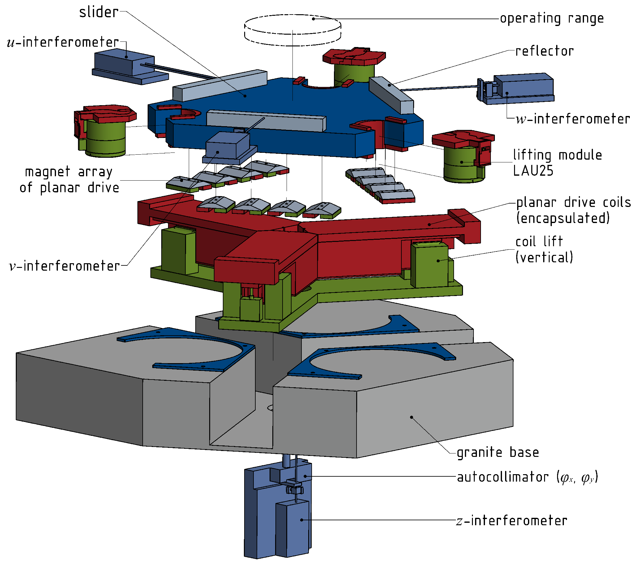
3.1. Stage Concept

The stage architecture of the NPS6D200 is based on the concept of an integrated planar direct drive for the long-range lateral positioning as it has been realized in earlier developments, see [28]. The main idea for the new development of the NPS6D200 is to extend this concept towards a vertical actuation in a macroscopic travel range with active control of all six degrees of freedom (DOFs). The integration of a high precision vertical actuation thereby leads to enhanced functional capabilities of the machine:
  • Compensate guiding deviations in z, φ x , φ y ;
  • Compensate vertical shift at tilted probes;
  • Measure 3D objects, tilted surfaces and macroscopic step heights;
  • Enable applications that require vertical displacements, e.g., focus height variations in interferometry, contour following mode in atomic force microscopy
  • Enable load/unload of the measurement object without having to remove the tool
In principle, the planar direct drive architecture is well suited to be enhanced by vertical actuation because of the planar arrangement of the drive components. Coils and magnets each are located in horizontal planes so that the slider is free to move vertically. Moreover, compared to a stacked axis arrangement the vertical actuation here can be implemented directly between the stator and the moving part. In this way, it is possible to maintain the advantages of the direct drive principle by continuing to have all actuation forces acting directly on the same body. This body is the so-called slider, and its movement is controlled in six DOFs. The displacements in x, y, z are available for large-scale movements, whereas the rotational DOFs are regulated to zero.
The schematic explosion illustration in Figure 1 shows the system composition and the main components. The slider, as the moving part of the 6D drive system, also carries the reflectors for the 6D feedback system so that these two central functions are incorporated in one and the same solid and rigid body. All drive forces act directly on this very body without any additional transfer elements. The result is a high stiffness in the actuation chain, which means in the mechanical path from the point of force application to the point where the displacement is measured. This high stiffness is linked to a good controllability. It allows for tuning the controller to higher bandwiths with robust phase margins and thereby enables better disturbance rejection and servo errors only at nanometer scale in closed loop control. The whole system follows a triangular configuration, which applies to the arrangement of the planar drive components and the laser interferometers (U, V, W) as planar feedback systems. This configuration also leads to a triangular slider shape with three-point support against the granite stator. These support points are formed by lifting modules (LAU25) which contain the vertical actuation as well as the aerostatic guiding both for the planar and the vertical slider motion. In combination, the three LAU25 represent the vertical drive system to address the z, φ x , φ y DOFs of the slider. Parallel to this, a planar direct drive system consisting of magnet arrays at the slider and encapsulated flat coils in the stator generates the required horizontal driving forces to control x, y, and φ z . Figure 2 shows a photograph of the NPS6D200, which in summary has the following key features:
  • Nanopositioning platform for Ø200 mm × 25 mm operating range;
  • Multiaxial direct drive system with contactless force application to the moving part;
  • Pneumatic weight force compensation;
  • Frictionless aerostatic guiding;
  • High resolution 6D measurement of the slider position;
  • 6D closed loop control;
  • Scalable design approach;
  • Open architecture to implement different applications and sensor tools.
In addition, Table 1 summarizes the key parameters of the realized drive system.
The 6D feedback system comprises four ultra-stable differential interferometers (DI) from SIOS GmbH [39] in an arrangement where the measurement beam paths intersect in one point so that it is virtually free of Abbe errors. Interferometers U, V, and W measure the planar motion of the slider in x, y, φ z . Note that interferometer U has both beam paths of the DI that lead to the moving reflector, so it directly measures the yaw angle. The pitch between the two beams here is Δ l = 14   mm . Together with the distance readings from V and W the coordinate transformation as given in Equation (1) results in x, y and φ z position of the slider. The vertical DOFs are addressed by the z interferometer and an autocollimator 2D angle sensor ( φ x , φ y ) which both look at the reflector on the slider’s underside. With measurement resolutions as listed in Table 2, this feedback system provides very high sensitivity for all six DOFs and thus forms another important prerequisite for achieving servo errors at the nanometer level with the NPS6D200.
x y φ z = 3 2 3 2 0 1 2 1 2 0 0 0 1 Δ l V W U
The fact that all six DOFs are controlled in closed loop ensures that the machine accuracy is independent of manufacturing tolerances or flatness deviations in the guiding system. Even in the rotational degrees of freedom, the position of the slider is not left to passive guidance and its deviations, but is regulated based on the 6D feedback system. This allows disturbances in these DOFs to be compensated, achieving higher positioning accuracy where only the mirror surfaces of the slider define the metrology.

3.2. Planar Drive System with Aerostatic Guiding

The integrated direct drive to control the planar motion is formed by a 120° arrangement of three linear actuators (A, B, C), each consisting of stationary flat coils and a magnet array fixed to the slider. This is illustrated in Figure 3. At each of the actuators, the force is generated as a Lorentz force between the coils and magnets, and the phase currents in the two coils are subject to a position-dependent commutation law to have the resulting force mainly horizontal and to minimize the parasitic vertical force components. The three forces of A , B , and C combine to the resulting driving forces in the x y plane ( F x , F y ) and the driving torque to control φ z , respectively. According to the 120° arrangement, this transformation reads as per
F x F y M φ z = 1 1 2 1 2 0 3 2 3 2 r F r F r F F A F B F C .
Table 3 lists the actuator constants of the individual drive units and the resulting planar motor, respectively.
The slider’s planar motion is guided by three planar air-bearing pads, each at the bottom of a lifting module. The reflectors are bonded directly to the slider and both are made of quartz glass to minimize susceptibility to thermal disturbances. For the same reason, the drive coils are encapsulated in a stainless steel housing with flat tempering channels on top and beneath the coils. Hence, this coil housing allows precise control of the temperature of the coil assemblies via a water cycle and a thermostat. Table 3 contains the main characteristics of the planar drive in the nominal state at the bottom of the 25 m m vertical working range. When the slider is lifted, the air gap between the coils and magnets increases beyond the nominal state, and the conditions for generating the planar drive forces change. The main effect here is a decrease in the efficiency of force generation, expressed by a decrease in the force constant of the actuators. Based on prior FEM simulations, a drop of approximately 50% was expected for a vertical displacement up to 10 m m . In view of this and with the desired vertical displacement of up to 25 m m , a coil lift functionality was developed and integrated into the stage design. The coil lift system displaces the star-shaped common base of the drive coil assemblies according to the slider’s z position so that the air gap between the coils and magnets remains close to the nominal level and the conditions for the generation of the planar driving forces do not change significantly with the sliders elevation. Thereby, the tracking motion of the coil lift system does not have to be highly precise because the air gap tolerates minor height variations. The primary design challenge here is ensure adequate lateral stiffness to accomodate the reaction forces at the coils. This is solved by means of an aerostatic guiding for the moving part which was developed together with AeroLas GmbH. With the whole system in operation, the drop in force constant was investigated in situ, and the results are contained in Figure 4 together with the corresponding increase in the coil currents and the closed loop servo error. The results confirm the expectations and indicate that the RMS servo error is not significantly affected by a levitation level of up to 6 m m . At this levitation height, the remaining force constant of the planar drive is approximately 2 3 of the nominal value. However, we conclude from these investigations that up to a vertical displacement of approximately 6 m m , the planar drive system does not experience substantial loss in performance and can be utilized even without repositioning the coils.

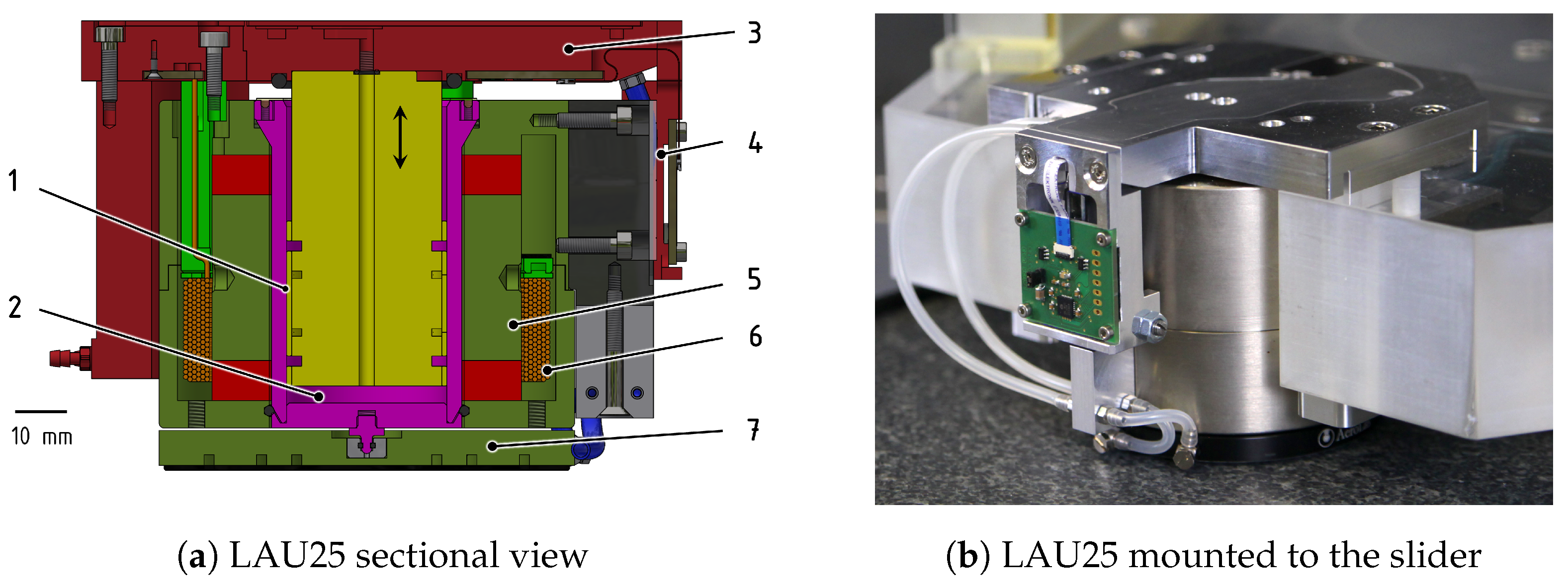
3.3. Vertical Drive System with Aerostatic Guiding and Weight Force Compensation
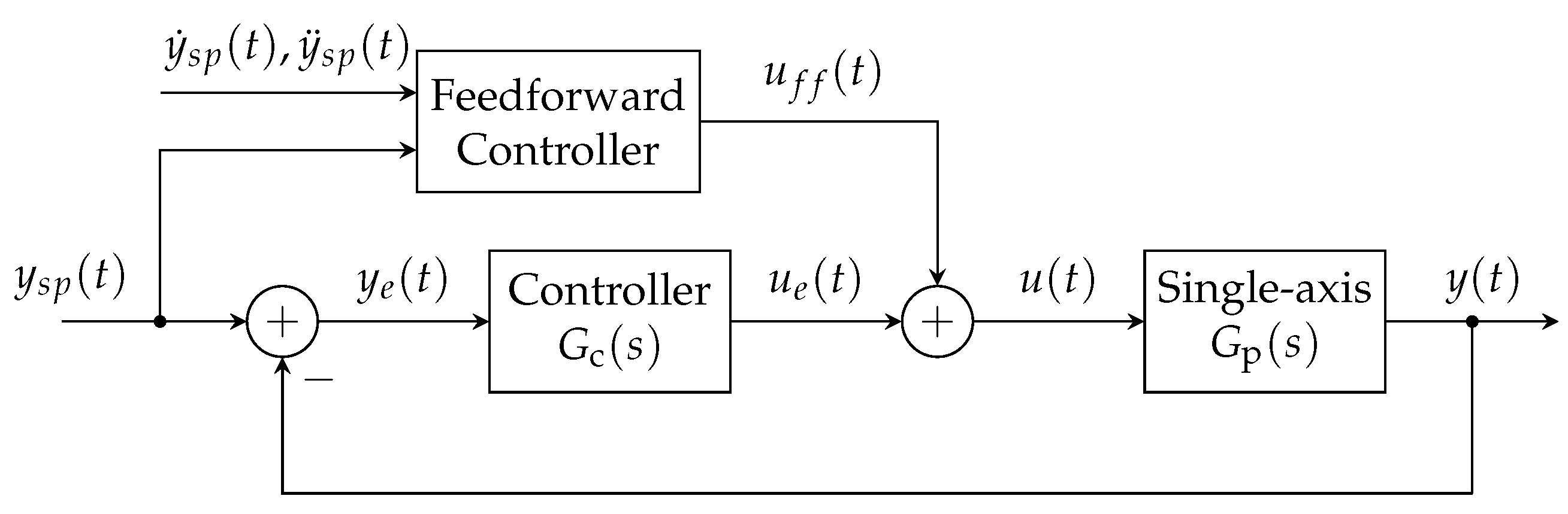
The precise vertical displacement of the quartz slider is accomplished by the combined operation of three lifting modules (LAU25) that are located at the corner points. Besides the pure translation in z, this also includes the rotational DOFs φ x and φ y . The three modules are identical, and their development for the implementation in the NPS6D200 follows the same approach as earlier realizations for 10 mm vertical stroke as described in [38,40]. Thereby, an individual lifting module integrates multiple functions into a compact mechanical design. These functions are listed in Table 4 together with the chosen technical realization in the current design.
Figure 5a illustrates a sectional view of the developed lifting modules where the design implementation of these functions is shown. The cylindrical shape of both the actuators (voice coil and pneumatic) and the guidings (planar and vertical) facilitates a compact concentric arrangement built around the central cylindrical linear guiding. The guided piston is, at the same time, part of the pneumatic actuator that arises from the pressurized chamber below the piston. By precisely controlling the pressure in this chamber, the static weight of the moving body is carried out without substantial heat generation. It is important to note that the sealing of this chamber is designed as a gap-sealing between the precisely manufactured surfaces of the air bushing and thus works without mechanical contact of the parts. In this way, disturbance forces and friction effects are avoided. Ring grooves separate the air bushing from the sealing gap and drain the exhaust air so that it does not leak into the surrounding area. By this means, the thermal disturbance to the overall system originating from the pneumatic components in the LAU is minimized. The voice coil works parallel to the pneumatic actuator, and its specific tailored design makes optimal use of the available design space. This Lorentz actuator is intended to generate only a dynamic force and, consequently, operate with zero DC current to minimize the power loss in the coil. In addition to these core components, an auxiliary linear feedback system is provided so that during initialization, an individual operation of each LAU is possible based on this feedback. Table 5 summarizes the characteristics of the LAU25 lifting modules.

3.4. Control System

The standard structure of the control system is shown in Figure 6. The core of the control hardware is a dSpace Scalexio rapid control prototyping system [41] where the control algorithm runs as a real-time task with 10   k Hz sample frequency. The controller task collects the 6D feedback signals via analog and digital inputs and calculates new target values for the different actuators based on the developed control law. The command values are the current and pneumatic pressure setpoints for the previously described planar and vertical actuators. An intermediate layer of control hardware, namely linear analog current amplifiers and high-precision pressure controllers, converts these command values into actual physical quantities—coil currents and pneumatic pressures—that are applied to the actuators in the motion stage.
Figure 7 illustrates an individual axis’s closed-loop block diagram. We developed six control laws for the motion controller, one for each axis, based on the classical PID approach, which is commonly used for this class of nanopositioning systems [42,43]. A set of filters then extends the aforementioned approach to attenuate disturbing resonances in the high-frequency band and, consequently, reduce positioning errors. The standard single-input single-output PID controller with dirty derivative in time-domain reads
υ d ( t ) = ω d 0 t υ d ( τ ) d τ + ω d y e ( t ) , u e ( t ) = K P y e ( t ) + K I 0 t y e ( τ ) d τ + K D υ d ( t ) ,
or equivalently in the Laplace domain
G c ( s ) = u e ( s ) y e ( s ) = K P 1 + K I s + K D ω d s s + ω d ,
constitutes a proper (implementable) transfer function where K P , K I , K D are positive constants. The controller parameters ( K P , K I , K D ) and cut-off frequency ω d of the dirty derivative are tuned independently for every axis featuring sufficiently robust stability, i.e., broad bandwidths, gain margins, and phase margins. Nevertheless, the performance of the proposed controller (4) is limited by the resonance modes in the high-frequency band. Thereby, each controller additionally includes a series connection of notch filters with low-pass filters to counteract these disturbing resonances. The band-stop and cut-off frequencies are adequately selected to attenuate specific resonances in the high-frequency band.
Figure 8 shows the measured bode response of a single axis together with the open loop frequency response for the x axis. The loop shape (Figure 8b) features remarkably robust stability margins, as was expected from the stage design. Although not shown here, the tuning procedure for the remaining motion axes is devised in an analogous manner using the measured frequency response, see Table 6.
Despite the exceptional performance of the presented PID-type controller (see Section 4), it is inherently limited to counteract simple disturbances and is quite sensitive to time-varying perturbations. However, further investigations on this topic have been reported in the literature [44,45,46,47] to cope with external waveform disturbances and parametric perturbations. Due to the fact that rapid disturbance rejection and guaranteed robustness are beyond the scope of this manuscript, the interested reader may refer to [48,49,50] and references therein to complement the discussion.

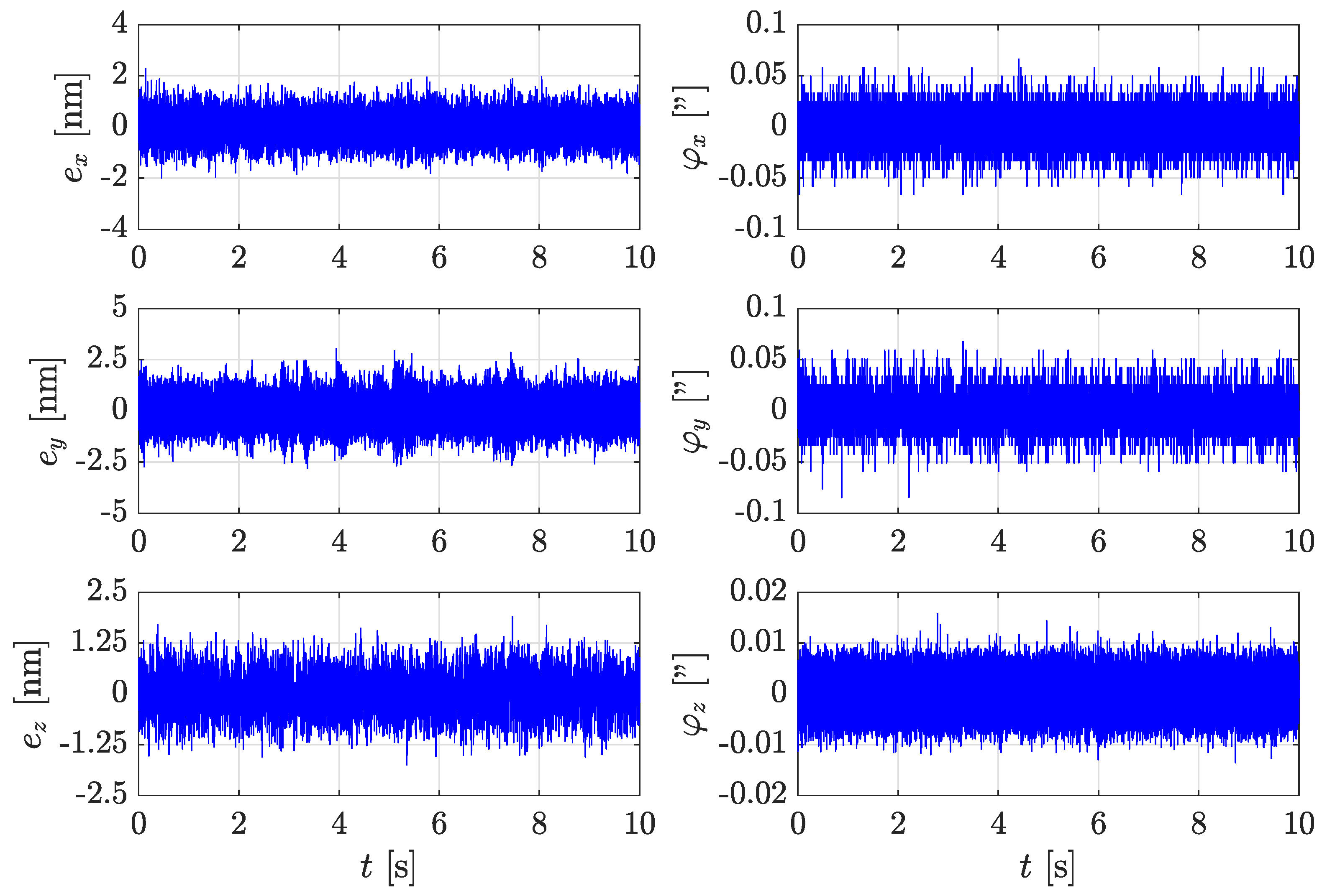
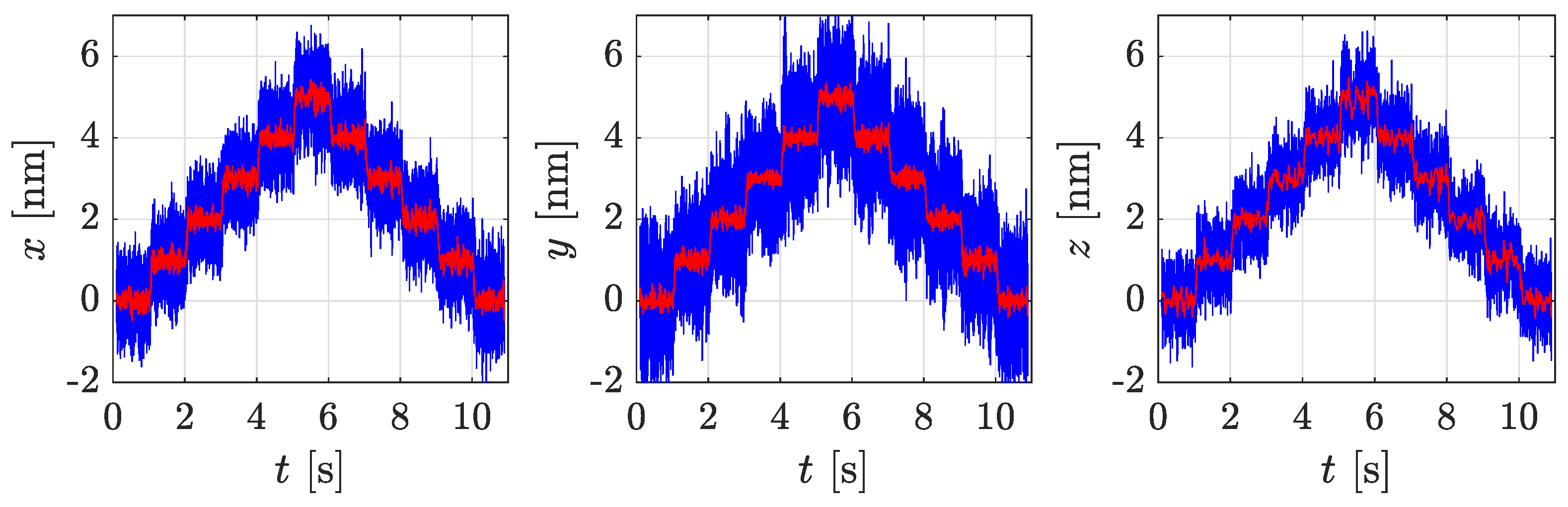
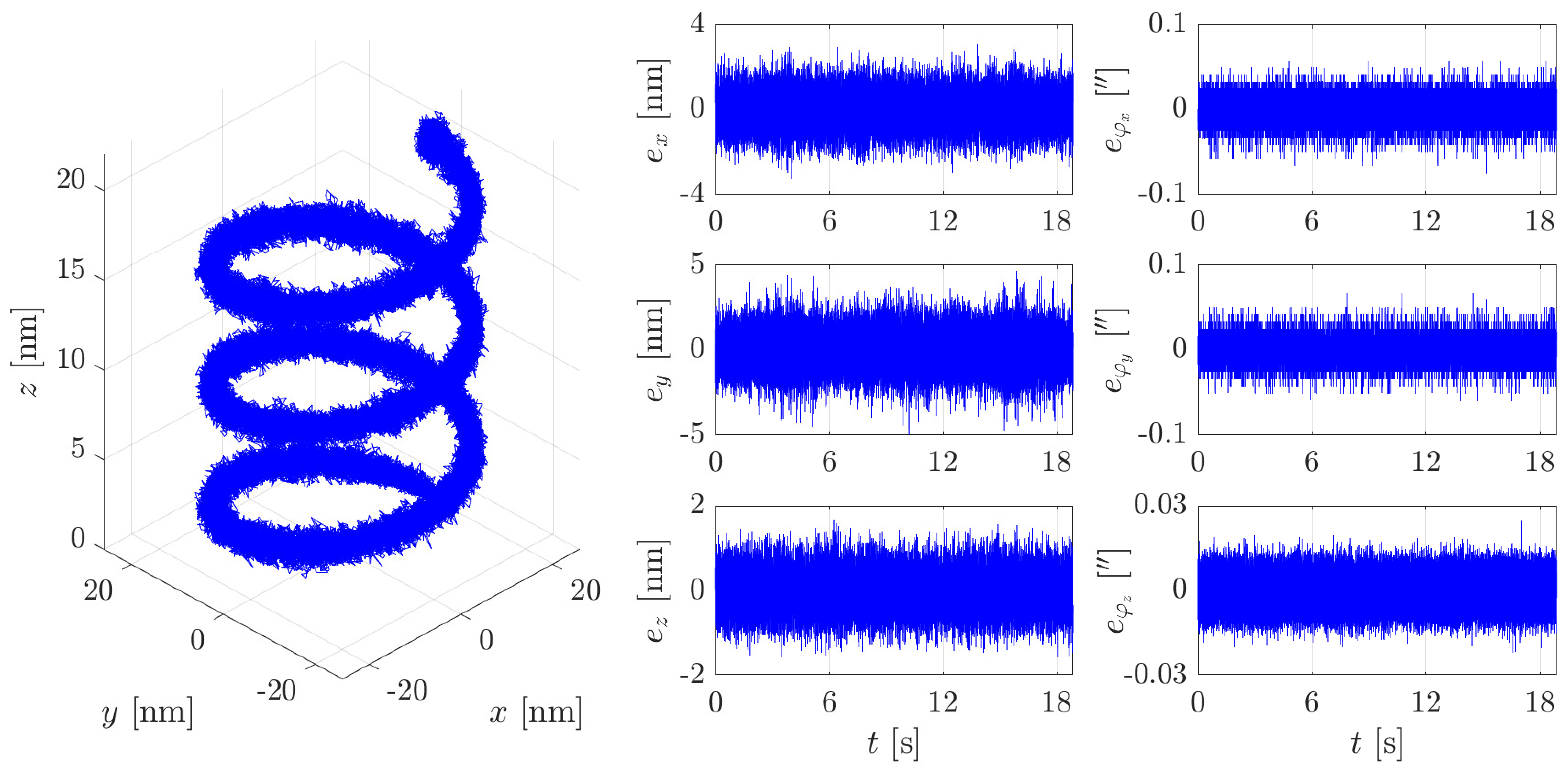
4. Positioning Characteristics in 6D Closed Loop Control

With the stage mechanics and control system as described in the previous chapters, the NPS6D200 was put into operation and now operates as a nanopositioning platform ready for the implementation of versatile tools or probes, depending on the advised application. Toward this end, it is important to investigate the positioning capabilities in order to assess the suitability for a specific task. In this chapter, we give an overview of the positioning scenarios that were considered and the respective positioning performance that is achieved with the NPS6D200.
The first important characteristic is the remaining servo error at a constant setpoint. Figure 9 shows the time signals of the six DOFs measured with the internal feedback system with the stage fully activated and at a constant setpoint in the center of the travel range. At this point, the conceptual benefits mentioned above pay off, and a remaining RMS servo error below 1 nm for x, y, and z is achieved with the developed controller.
When the slider changes its position within the planar and vertical travel range, the mechanical conditions of the force transfer change, and accordingly, a change in control behavior is expected. In corresponding investigations, we find that the servo errors vary slightly within the lateral travel range of Ø 200   m m , but nonetheless, they remain in the range below 1.5   n m (RMS), as depicted in Figure 10. Also, concerning the vertical slider position, only a minor servo error variation below 1 nm is observed, as shown in Figure 11. This performance in static setpoint operation opens the path for deterministic motion at the nanometer level, which is demonstrated by the illustrative staircase exercise shown in Figure 12.
In a second set of experiments the tracking performance was evaluated by means of 3D positioning exercises that require simultaneous and synchronized movements in the different axes. Such exercises reveal remaining parasitic cross-coupling effects between the DOFs and are well suited as a performance test for complex 3D motion paths. To analyze the occurence and extend of these effects we execute a stage movement along a helix with varying dimensions from the nanometer (Ø40 n m × 20 n m ) to the millimeter (Ø40 m m × 5 m m ) range. The stage velocity is adapted accordingly and ranges from 7 n m s 1 up to 7 m m s 1 . Together with the tracking errors, the control effort and the power loss in the actuators are analyzed because of their great importance for any future application scenario. Exemplarily, Figure 13 shows the result of positioning a helix with Ø 40   n m and a path velocity of 7   n m s 1 while Table 7 summarizes the achieved tracking errors and current consumptions connected to the different helix positioning exercises. As can be seen from the table, we obtained servo errors in the low nanometer range together with currents in the range of only milliamperes. From that we conclude that only very little parasitic effects occur as a benefit of the stage design, the weight force compensation, and the consequent application of aerostatic guiding. Furthermore, the developed controller can handle the remaining disturbances quite well, which is a consequence of the its design and the achieved stability margins, as given in Table 6. For a more detailed view into the controller design towards decoupling and disturbance rejection the reader may refer to [47].
These positioning characteristics are already very promising and show the suitability of the NPS6D200 for nanopositioning tasks in large 3D operating ranges. They provide a basis for further detailed investigations for example towards reproducibility and measurement uncertainty, in combination with adequate probing systems.

5. Conclusions and Outlook

The developed long-range nanopositioning system NPS6D200 follows a comprehensive design approach that focuses on direct force application in combination with aerostatic guiding and laser interferometer feedback. The analysis of the system’s positioning capabilities confirms the design approach and shows that within the operating range of Ø200 m m × 25 m m positioning with nanometer stability and sensitivity is attained. The system’s main limitation is the lack of active angular positioning within the rotational DOFs and, thus, no possible stage slider inclination. The NPS6D200 positioning system obtains servo errors in the low-nanometer range both in constant setpoint operation and in synchronized multiaxial motion. This is achieved in a large operating range and along with very low heat emission and minimized disturbance introduction into the measurement volume. With this combination, the NPS6D200 is well suited as a positioning platform for nanotechnology research applications that on the one hand require such precise and deterministic position control between tool and substrate up to wafer-size and that on the other hand rely on minimized disturbance entry into the area of interaction. Such applications are for example wafer-based inspection, long-range atomic force microscopy scans, and sub-10 nm nanofabrication techniques, to name but a few.
In general the architecture approach is scalable and realisations with larger operating ranges are possible. Regarding the planar operation range, the slider size would increase accordingly and this needs to be addressed by a lightweight design of the slider in order to reduce the moving mass and maintain sufficiently high eigenfrequencies. The vertical movement is based on the lifting modules (LAUs) and the coil-lift functionality and a redesign of both subsystem to a larger vertical stroke is feasible. Based on the achieved performance in 25 mm, a similar positioning performance in sub-10 nm range can be expected also for larger vertical positioning ranges.
Oncoming research will focus on analyzing and reducing the remaining error sources and position-dependent effects to further improve the positioning characteristics. Parallel to that, current research already investigates the integration of probing and manipulation systems to further extend the performance analysis to entire application scenarios and to complement the NPS6D200 into a fully functional nanofabrication tool.

Author Contributions

Conceptualization, S.H., A.H. and M.K.; methodology, S.H., A.H. and M.K.; validation, S.H. and M.K.; investigation, S.H., A.H., M.K. and B.L.; writing—original draft preparation, S.H. and A.H.; visualization, S.H. and A.H.; writing—review and editing, S.H., A.H., B.L., M.K. and L.H. All authors have read and agreed to the published version of the manuscript.

Funding

This research was supported by the German “Land” of Thüringen in the scope of the internal research group “Next Generation Positioning” and by the German Federal Ministry for Economic Affairs and Energy (BMWi)/Federal Ministry for Economic Affairs and Climate Action (BMWK) in the scope of the project “K4PNP+Z” under the reference ZF4085714JO9.

Institutional Review Board Statement

Not applicable.

Informed Consent Statement

Not applicable.

Data Availability Statement

Research data are available upon request to the authors.

Acknowledgments

The authors gratefully acknowledge the fruitful cooperation with the Institute of Process Measurement and Sensor Technology at TU Ilmenau as well as with SIOS GmbH and AeroLas GmbH.

Conflicts of Interest

The authors declare that the research was conducted in the absence of any commercial or financial relationships that could be construed as a potential conflict of interest.

Abbreviations

The following abbreviations are used in this manuscript:
DOFDegree of freedom
LAULifting and actuation unit
NPSNanopositioning system
CMMCoordinate measurement machine
DIDifferential interferometer
RMSRoot mean square
PIDProportional integral derivative (controller)

References

  1. Chen, Y.; Shu, Z.; Zhang, S.; Zeng, P.; Liang, H.; Zheng, M.; Duan, H. Sub-10 nm fabrication: Methods and applications. Int. J. Extrem. Manuf. 2021, 3, 032002. [Google Scholar] [CrossRef]
  2. The International Roadmap for Devices and Systems: 2022. Technical Report, Executive Summary. 2022. Available online: https://irds.ieee.org/editions/2022/executive-summary (accessed on 28 March 2024).
  3. Oh, D.K.; Jeong, H.; Kim, J.; Kim, Y.; Kim, I.; Ok, J.G.; Rho, J. Top-down nanofabrication approaches toward single-digit-nanometer scale structures. J. Mech. Sci. Technol. 2021, 35, 837–859. [Google Scholar] [CrossRef]
  4. He, Y.X.; Lin, R.W.; Li, R.J.; Li, J.; Cheng, Z.Y.; Pan, Q.S.; Huang, Q.X.; Fan, K.C. Nanopositioning X–Y stage with an embedded Six-DOF error compensation system based on Abbe and Bryan principles. Measurement 2024, 227, 114218. [Google Scholar] [CrossRef]
  5. Fan, K.C.; Fei, Y.T.; Yu, X.; Chen, Y.; Wang, W.L.; Chen, F.; Liu, Y. Development of a low-cost micro-CMM for 3D micro/nano measurements. Meas. Sci. Technol. 2006, 17, 524. [Google Scholar] [CrossRef]
  6. Kim, W.J.; Verma, S.; Shakir, H. Design and precision construction of novel magnetic-levitation-based multi-axis nanoscale positioning systems. Precis. Eng. 2007, 31, 337–350. [Google Scholar] [CrossRef]
  7. Ro, S.K.; Park, J.K. A compact ultra-precision air bearing stage with 3-DOF planar motions using electromagnetic motors. Int. J. Precis. Eng. Manuf. 2011, 12, 115–119. [Google Scholar] [CrossRef]
  8. Werner, C. A 3D Translation Stage for Metrological AFM. Ph.D. Thesis, Technische Universiteit Eindhoven, Eindhoven, The Netherlands, 2010. [Google Scholar] [CrossRef]
  9. Hocken, R.J.; Fesperman, R.; Overcash, J.; Ozturk, O.; Stroup, C. Engineering nanotechnology: The top down approach. Key Eng. Mater. 2008, 381, 3–6. [Google Scholar] [CrossRef]
  10. Brand, U.; Kirchhoff, J. A micro-CMM with metrology frame for low uncertainty measurements. Meas. Sci. Technol. 2005, 16, 2489. [Google Scholar] [CrossRef]
  11. Hausotte, T. Nanopositionier-und Nanomessmaschine. Ph.D. Thesis, Technische Universität Ilmenau, Ilmenau, Germany, 2002. [Google Scholar]
  12. Moers, A.; van Riel, M.C.; Bos, E.J. Design and Verification of the Trinano Ultra Precision CMM; Universitätsbibliothek Ilmenau: Ilmenau, Germany, 2011. [Google Scholar]
  13. Abbe, E. Messapparate für Physiker. Z. Instrumentenkunde 1890, 10, 446–448. [Google Scholar]
  14. Bryan, J.B. The Abbe principle revisited: An updated interpretation. Precis. Eng. 1979, 1, 129–132. [Google Scholar] [CrossRef]
  15. Schellekens, P.; Rosielle, N.; Vermeulen, H.; Vermeulen, M.; Wetzels, S.; Pril, W. Design for precision: Current status and trends. CIRP Ann. 1998, 47, 557–586. [Google Scholar] [CrossRef]
  16. Yagüe-Fabra, J.A.; Gao, W.; Archenti, A.; Morse, E.; Donmez, A. Scalability of precision design principles for machines and instruments. CIRP Ann. 2021, 70, 659–680. [Google Scholar] [CrossRef]
  17. Torralba, M.; Yagüe-Fabra, J.A.; Albajez, J.A.; Aguilar, J.J. Design optimization for the measurement accuracy improvement of a large range nanopositioning stage. Sensors 2016, 16, 84. [Google Scholar] [CrossRef] [PubMed]
  18. Yoshioka, H.; Sawano, H.; Shinno, H. A newly developed ultraprecision machine tool ‘angel’. In Proceedings of the 10th Euspen International Conference, Delft, The Netherlands, 31 May–4 June 2010; Volume 2, p. 239. [Google Scholar]
  19. Widdershoven, I.; Donker, R.; Spaan, H. Realization and calibration of the “Isara 400” ultra-precision CMM. In Proceedings of the 13th International Conference on Metrology and Properties of Engineering Surfaces, Twickenham, UK, 12–15 April 2011; IOP Publishing: Bristol, UK, 2011; Volume 311, p. 012002. [Google Scholar]
  20. Vermeulen, M.M.P.A.; Rosielle, P.; Schellekens, P. Design of a high-precision 3D-coordinate measuring machine. CIRP Ann. 1998, 47, 447–450. [Google Scholar] [CrossRef]
  21. Seggelen, J. NanoCMM; A 3D Coordinate Measuring Machine with Low Moving Mass for Measuring Small Products in Array with Nanometer Uncertainty. Ph.D. Thesis, Eindhoven University of Technology, Eindhoven, The Netherlands, 2007. [Google Scholar]
  22. Ruijl, T.A.M. Ultra Precision Coordinate Measuring Machine-Design, Calibration and Error Compensation. Ph.D. Thesis, Technische Universiteit Delft, Delft, The Netherlands, 2001. [Google Scholar]
  23. Tsutsumi, H.; Yoshizumi, K.; Takeuchi, H. Ultrahighly accurate 3D profilometer. Optical Design and Testing II. Photonics Asia. Proc. SPIE 2005, 5638, 387–394. [Google Scholar]
  24. Chung, T.T.; Chu, C.H.; Chian, H.F.; Huang, C.; Fan, K.C.; Yen, J.Y.; Szu, K.I. Structural design and analysis of a nano-positioning planar motion stage. In Proceedings of the 2011 9th World Congress on Intelligent Control and Automation, Taipei, Taiwan, 21–25 June 2011; pp. 833–838. [Google Scholar]
  25. Liu, C.H.; Jywe, W.Y.; Jeng, Y.R.; Hsu, T.H.; Li, Y.T. Design and control of a long-traveling nano-positioning stage. Precis. Eng. 2010, 34, 497–506. [Google Scholar] [CrossRef]
  26. Kallenbach, E.; König, K.; Saffert, E.; Schäffel, C.; Eccarius, M. Integrated Design of Shape and Function in Mechatronic Systems. In From Design Methods to Industrial Applications, Proceedings of the Third Conference on Mechatronics and Robotics, Paderborn, Germany, 4–6 October 1995; Springer: Berlin/Heidelberg, Germany, 1995; pp. 44–51. [Google Scholar]
  27. Hesse, S.; Schäffel, C.; Katzschmann, M.; Maaß, T.; Mohr, H. Planar motor concept for positioning with nanometer position uncertainty. In Proceedings of the 8th International Conference of the European Society for Precision Engineering and Nanotechnology, Zurich, Switzerland, 18–21 August 2008; pp. 150–154. [Google Scholar]
  28. Hesse, S.; Schäffel, C.; Mohr, H.U.; Katzschmann, M.; Büchner, H.J. Design and performance evaluation of an interferometric controlled planar nanopositioning system. Meas. Sci. Technol. 2012, 23, 074011. [Google Scholar] [CrossRef]
  29. Jäger, G.; Hausotte, T.; Manske, E.; Büchner, H.J.; Mastylo, R.; Dorozhovets, N.; Hofmann, N. Nanomeasuring and nanopositioning engineering. Measurement 2010, 43, 1099–1105. [Google Scholar] [CrossRef]
  30. Manske, E.; Jäger, G.; Hausotte, T.; Füßl, R. Recent developments and challenges of nanopositioning and nanomeasuring technology. Meas. Sci. Technol. 2012, 23, 074001. [Google Scholar] [CrossRef]
  31. Manske, E.; Fröhlich, T.; Füßl, R.; Ortlepp, I.; Mastylo, R.; Blumröder, U.; Dontsov, D.; Kühnel, M.; Köchert, P. Progress of nanopositioning and nanomeasuring machines for cross-scale measurement with sub-nanometre precision. Meas. Sci. Technol. 2020, 31, 085005. [Google Scholar] [CrossRef]
  32. Kühnel, M.; Ortlepp, I.; Hofmann, M.; Weidenfeller, L.; Kirchner, J.; Supreeti, S.; Mastylo, R.; Füßl, R.; Rangelow, I.; Fröhlich, T.; et al. Nanopositioning and Nanomeasuring Machines (NPMM) and their application for nanofabrication in extended working volumes. In Proceedings of the 14th International Symposium on Measurement Technology and Intelligent Instruments ISMTII, Niigata, Japan, 1–4 September 2019. [Google Scholar]
  33. Ortlepp, I.; Fröhlich, T.; Füßl, R.; Reger, J.; Schäffel, C.; Sinzinger, S.; Strehle, S.; Theska, R.; Zentner, L.; Zöllner, J.P.; et al. Tip-and laser-based 3D nanofabrication in extended macroscopic working areas. Nanomanuf. Metrol. 2021, 4, 132–148. [Google Scholar] [CrossRef]
  34. Fern, F.; Fuessl, R.; Manske, E.; Schienbein, R.; Theska, R.; Ortlepp, I.; Leineweber, J. Measurement uncertainty analysis on a five-axis nano coordinate measuring machine NMM-5D following a vectorial approach. Tech. Mess. 2021, 88, 61–70. [Google Scholar] [CrossRef]
  35. Stauffenberg, J.; Ortlepp, I.; Blumröder, U.; Dontsov, D.; Schäffel, C.; Holz, M.; Rangelow, I.W.; Manske, E. Investigations on the positioning accuracy of the Nano Fabrication Machine (NFM-100). Tech. Mess. 2021, 88, 581–589. [Google Scholar] [CrossRef]
  36. Stauffenberg, J.; Ortlepp, I.; Belkner, J.; Dontsov, D.; Langlotz, E.; Hesse, S.; Rangelow, I.; Manske, E. Measurement precision of a planar nanopositioning machine with a range of motion of Ø100 mm. Appl. Sci. 2022, 12, 7843. [Google Scholar] [CrossRef]
  37. Stauffenberg, J.; Reibe, M.; Krötschl, A.; Reuter, C.; Ortlepp, I.; Dontsov, D.; Hesse, S.; Rangelow, I.W.; Strehle, S.; Manske, E. Tip-based nanofabrication below 40 nm combined with a nanopositioning machine with a movement range of Ø100 mm. Micro Nano Eng. 2023, 19, 100201. [Google Scholar] [CrossRef]
  38. Gorges, S.; Hesse, S.; Schäffel, C.; Ortlepp, I.; Manske, E.; Langlotz, E.; Dontsov, D. Integrated planar 6-DOF nanopositioning system. IFAC-PapersOnLine 2019, 52, 313–318. [Google Scholar] [CrossRef]
  39. SIOS GmbH. Differential Laser Interferometer SP 5000 DI/F. 2024. Available online: https://www.sios-precision.com/en/products/length-measurement-systems/differential-laser-interferometer-sp-5000-di-f (accessed on 24 May 2024).
  40. Gorges, S. A Lifting and Actuating Unit for a Planar Nanoprecision Drive System. Ph.D. Thesis, Technische Universität Ilmenau, Ilmenau, Germany, 2020. [Google Scholar]
  41. dSpace GmbH. Scalexio Modular Real-Time System. 2024. Available online: https://www.dspace.com/en/pub/home/products/hw/simulator_hardware/scalexio.cfm (accessed on 27 May 2024).
  42. Eleftheriou, E.; Moheimani, S.R. Control Technologies for Emerging Micro and Nanoscale Systems; Springer: Berlin/Heidelberg, Germany, 2011; Volume 413. [Google Scholar]
  43. Fleming, A.J.; Leang, K.K. Design, Modeling and Control of Nanopositioning Systems; Springer: Berlin/Heidelberg, Germany, 2014. [Google Scholar]
  44. Huaman, A.S.; Reger, J. Robust Tracking Control with L1 Adaptive Augmentation for a Long-Stroke Vertical Nanopositioning System: Part I. In Proceedings of the IEEE Conference on Control Technology and Applications (CCTA), Trieste, Italy, 23–25 August 2022; pp. 614–620. [Google Scholar]
  45. Huaman, A.S.; Reger, J. Robust Tracking Control with L1 Adaptive Augmentation for a Long-Stroke Vertical Nanopositioning System: Part II. In Proceedings of the IEEE Conference on Control Technology and Applications (CCTA), Trieste, Italy, 23–25 August 2022; pp. 621–627. [Google Scholar]
  46. Huaman, A.S.; Reger, J. Robust Adaptive Tracking Control of a 3D Vertical Motion System for Nanometer Precision Applications. IFAC World Congr. 2023, 56, 5332–5339. [Google Scholar] [CrossRef]
  47. Huaman, A.S. Highly Dynamic Nanopositioning: A Robust Adaptive Control Approach. Ph.D. Thesis, Technische Universität Ilmenau, Ilmenau, Germany, 2024. [Google Scholar]
  48. Hovakimyan, N.; Cao, C. L1 Adaptive Control Theory: Guaranteed Robustness with Fast Adaptation; SIAM: Philadelphia, PA, USA, 2010. [Google Scholar]
  49. Gibson, T.E.; Annaswamy, A.M.; Lavretsky, E. On adaptive control with closed-loop reference models: Transients, oscillations, and peaking. IEEE Access 2013, 1, 703–717. [Google Scholar] [CrossRef]
  50. Zhao, P.; Snyder, S.; Hovakimyan, N.; Cao, C. Robust adaptive control of linear parameter-varying systems with unmatched uncertainties. J. Guid. Control. Dyn. 2024, 1–18. [Google Scholar] [CrossRef]
Figure 1. NPS6D200 main components and general arrangement.
Applsci 14 06972 g001
Figure 2. Photograph of NPS6D200 long range nanopositioning stage. Components: 1—slider with reflectors. 2—magnets of the planar direct drive (moving with the slider). 3—coils of the planar direct drive (encapsulated) 4—laser interferometer. 5—granite portal with probe mount interface. 6—laser interferometer. 7—lifting module LAU25. 8—granite base.
Applsci 14 06972 g002
Figure 3. Components of the planar direct drive and their arrangement. Note: The top part of the coil encapsulation is not shown for visibility of drive coils.
Applsci 14 06972 g003
Figure 4. Measured effects on the planar drive system due to lifting of the slider (coils remain at initial height). ( b l a c k ) —force constant of the linear actuators. ( b l u e ) —servo error (RMS) in x (solid) and y (dashed). ( r e d ) —required controller current (RMS) in x (solid) and y (dashed).
Applsci 14 06972 g004
Figure 5. Lifting and actuation module LAU25. 1—Air bushing as vertical guiding. 2—Pressure chamber of pneumatic weight force compensation. 3—Moving part (mounted to the slider). 4—Encoder measurement system. 5—Voice coil actuator, iron core. 6—Voice coil actuator, coil part (moving). 7—planar air bearing.
Applsci 14 06972 g005
Figure 6. Basic control structure of the NPS6D200. Signals with subscript ( · ) p and ( · ) v indicate planar and vertical quantities, respectively. Signals with superscript ( · ) refer command values.
Applsci 14 06972 g006
Figure 7. Control scheme for individual axis controller, where y s p is the commanded setpoint, y is the measured output, and u is the control effort.
Applsci 14 06972 g007
Figure 8. Bode response of the x -axis.
Applsci 14 06972 g008
Figure 9. Position time series in closed loop control at constant setpoint. RMS servo error: e x =   0.47   n m , e y =   0.68   n m , e z =   0.41   n m , e φ x =   11.21   m , e φ y =   9.83   m , e φ z =   3.03   m .
Applsci 14 06972 g009
Figure 10. RMS servo error variation within planar travel range.
Applsci 14 06972 g010
Figure 11. RMS servo error variation within vertical travel range measured at ( x , y ) = ( 0 , 0 ) mm . ( b l u e ) e x , ( r e d ) e y , ( b l a c k ) e z .
Applsci 14 06972 g011
Figure 12. Nanometer staircase exercise in x , y and z direction (from left to right). ( b l u e ) —raw data traced with 10 kHz, ( r e d ) —filtered data (4th order Chebyshev low pass, 40 Hz cutoff frequency).
Applsci 14 06972 g012
Figure 13. 3D motion exercise with a Ø40 n m helix. ( l e f t ) —plot of the 3D position signals. ( r i g h t ) —servo error time series in the 6 DOFs during trajectory motion.
Applsci 14 06972 g013
Table 1. Key parameters of the positioning system.
ParameterValue
x y -operating rangeØ200 m m
z-operating range25 m m
planar velocity 150 m m s 1
vertical velocity2 m m s 1
acceleration250 m m s 2
moving mass36 k g
payload5 k g
overall dimensions (W × L × H)1115 m m × 980 m m × 980 m m
1 This is the current maximum velocity setting. It may be increased if required.
Table 2. Measurement resolutions of the feedback system.
ParameterValue
displacement measurement resolution V, W, Z20 p m
resulting feedback resolution x17 p m
resulting feedback resolution y10 p m
angular resolution φ z 1.4   n rad
angular resolution φ x , φ y 40 n rad
Table 3. Key actuation parameters of the integrated planar direct drive.
ParameterValue
linear actuator force constant 6.0   N A 1
linear actuator motor constant 3.8   N / W
planar drive motor constant 4.6   N / W
Table 4. Lifting module subfunctions.
FunctionDescriptionDesign Choice
dynamic actuationgeneration of vertical driving force with high sensitivity and high bandwidthvoice coil actuator, moving coil
quasistatic actuationgeneration of vertical driving force with high sensitivity and low bandwidthpneumatic actuator with contactless sealing
planar guidingfrictionless support of the moving bodyplanar air bearing pad
vertical guidingfrictionless internal guiding for 25 mm vertical strokecylindrical air bushing
displacementmeasurementinternal measurement of the LAU displacementoptical encoder with linear scale
Table 5. Key parameters of the lifting module LAU25.
SubsystemParameterValue
mechanicsz—strokemass
moving part
mass stationary part
size (ØD × H)
25 m m
0.7   k g
1.7   k g
Ø83 m m  ×  90 m m
voice coil actuatorforce constant
motor constant
maximum current
current increment (LSB)
9.9   N A 1
14.0   N / W
1.3   A
0.04   m A
pneumatic actuatorforce constant
maximum pressure
pressure increment (LSB)
80.4   N bar 1
2.0   bar
0.06   mbar
aerostatic guidingsupply pressure
supply air flow
drain air flow
4.0 bar
1.9   NLPM
1.7   NLPM
encoder feedback systemscale pitch
measurement resolution
256 μ m
4 μ m
Table 6. Robustness and performance parameters for all six closed loops.
Specifications x -axis y -axis φ z -axis z -axis φ x -axis φ y -axis
Gain margin 11.5 dB 11.8 dB 16.1 dB 14.7 dB 15.4 dB 15.2 dB
Phase margin 39.1 37.5 41.8 39.5 40.6 40.9
Bandwidth 85.5 Hz 88.4 Hz 72.8 Hz 95.1 Hz 76.7 Hz 75.2 Hz
Table 7. Summarized results of helix trajectory tracking exercises.
Commanded
Helix Path
RMS Servo ErrorsRMS Currents
(Planar Coils)
RMS Currents
(Lifting Modules)
Ø40 n m × 20 n m
v = 7 n m s 1
e x = 0.71   n m
e y = 0.88   n m
e z = 0.39   n m
i A = 6.39   m A
i B = 27.28   m A
i C = 11.04   m A
i 1 = 0.5   m A
i 2 = 0.51   m A
i 3 = 0.46   m A
Ø40 μ m × 50 μ m
v = 7 μ m s 1
e x = 2.36   n m
e y = 2.66   n m
e z = 0.49   n m
i A = 6.61   m A
i B = 27.41   m A
i C = 11.29   m A
i 1 = 0.5   m A
i 2 = 0.51   m A
i 3 = 0.46   m A
Ø40 m m × 5 m m
v = 7 m m s 1
e x = 0.93   n m
e y = 1.66   n m
e z = 0.67   n m
i A = 50.32   m A
i B = 74.71   m A
i C = 67.45   m A
i 1 = 5.15   m A
i 2 = 5.71   m A
i 3 = 4.56   m A
Disclaimer/Publisher’s Note: The statements, opinions and data contained in all publications are solely those of the individual author(s) and contributor(s) and not of MDPI and/or the editor(s). MDPI and/or the editor(s) disclaim responsibility for any injury to people or property resulting from any ideas, methods, instructions or products referred to in the content.

