Article

A New Semi-Analytical Method for the Calculation of Multi-Crack Stress-Intensity Factors under Hydro-Mechanical Coupling

1
College of Water Resources & Civil Engineering, Hunan Agricultural University, Changsha 410128, China
2
School of Civil Engineering, Central South University, Changsha 410083, China
*
Author to whom correspondence should be addressed.
Appl. Sci. 2024, 14(16), 7083; https://doi.org/10.3390/app14167083
Submission received: 17 July 2024 / Revised: 6 August 2024 / Accepted: 11 August 2024 / Published: 12 August 2024

Abstract

:
Calculating the hydro-mechanical coupling stress-intensity factor (SIF) is an important basis for conducting safety evaluations in geotechnical engineering. The current methods used to calculate hydro-mechanical coupling multi-crack SIFs have difficulties concerning their complicated solution processes and unsuitable stress field expressions. In this paper, a new semi-analytical method is proposed based on a new hydro-mechanical coupling stress function and the extended reciprocal theorem of the work integral formula to calculate hydro-mechanical coupling multi-crack SIFs, which can be verified by comparison with the results available in the literature. The new semi-analytical method is applicable to an arbitrary number of cracks under arbitrary hydro-mechanical coupling loading and facilitates a more effective representation of the water pressure effect on the stress field. Moreover, the influence of the integral path and loading conditions is also discussed, and the results revealed an integral path radius of r2 < 0.75 mm when the crack spacing b is 1.5 mm. When σy and Ph are constant at 15 MPa, the SIFs are almost the same for different σy/Ph, while the maximum circumferential stresses at r = 0.25 mm are 15.79 MPa, 20.83 MPa, and 25.78 MPa.

1. Introduction

Hydraulic cracks are prevalent in geotechnical engineering, and water pressure can cause the tensile stress at the crack tip to significantly increase compared to normal cracks, leading to easier crack initiation. Furthermore, under the action of hydraulic pressure and far-field external loads, hydraulic cracks will rapidly initiate, expand, and connect, eventually forming a crack network and increasing the difficulty of conducting geotechnical safety assessments. Crack networks are a considerable threat to the safety of hydraulic engineering (such as in the case of dams [1] and hydraulic tunnels [2]); however, their formation has a positive significance in terms of improving the efficiency of mining engineering (such as in the context of shale gas extraction [3], geothermal energy development [4], and CO2 geological storage [5]). Whether in the case of anti-cracking in hydraulic engineering or cracking in mining engineering, hydro-mechanical coupling stress-intensity factor (SIF) calculations for multiple cracks are the basis of the analyses. SIF calculations can be used to differentiate crack initiation mechanisms (including crack initiation load and initiation angle) under hydro-mechanical coupling conditions in geotechnical engineering and can also be used to determine whether a crack network will form in the engineering structure, thus providing a theoretical basis for conducting safety evaluations in the context of geotechnical engineering. Therefore, it is of great significance to study the calculation methods used for hydro-mechanical coupling SIFs for multi-cracks.
Currently, the calculation method used in the case of multi-crack SIFs focuses mainly on mechanical loading. Chen and Chang [6] used the alternating method and the iterative method to solve multi-crack SIFs under load on the crack surface. Niu and Wu [7] used the dislocation theory and the superposition method to obtain multi-crack SIFs under far-field compressive stress. Rohde et al. [8] adopted the energy method to calculate multi-crack SIFs in symmetrical structures. However, these methods have limitations since they are applicable only to specific structural and loading situations. In order to overcome these problems, scholars have conducted further research. Wang and Atluri [9] proposed the Schwartz–Neumann alternating method to determine the SIFs of co-linear cracks with arbitrary boundary conditions. Hejazi et al. [10] and Kachanov [11] used the Laplace transform method and the extended superposition method to obtain the SIFs for arbitrarily distributed multi-cracks, respectively. Gorbatikh et al. [12] modified Kachanov’s method based on the assumption of non-uniform terms and obtained the SIFs for multi-cracks with small spacings. Nevertheless, since these complex auxiliary functions (e.g., the Laplace transform function, the dislocation density function, and the alternating transform function) depend on the loading conditions, they are difficult to apply when solving cases involving complex hydro-mechanical coupling loading.
The calculation methods used to solve multi-crack hydro-mechanical coupling SIFs rely mainly on numerical methods. Sapora et al. [13] developed a numerical model to analyze hydro-mechanical coupling SIFs and initiation lengths based on finite fracture mechanics (FFMs). Zhang et al. [14] adopted the second-order numerical manifold method and the singular boundary element method to calculate hydro-mechanical coupling SIFs under seepage conditions. Zhao et al. [15] established a new finite element model based on the equivalence theory and calculated hydro-mechanical coupling SIFs with wing cracks. Wu et al. [16] used the virtual crack closure technique (VCCT) to calculate the hydraulic coupling stress-intensity factors for arbitrarily shaped cracks. Cheng et al. [17] adopted the level set method to describe holes and cracks in a numerical model and combined it with the extended finite element method (XFEM) to obtain hydro-mechanical coupling SIFs. However, since the computational accuracy of the numerical method depends on the refinement of the crack-tip element, it is difficult to obtain accurate computational results when the spacing of multiple cracks is small (i.e., it is difficult to refine the crack-tip element).
In order to improve the calculation accuracy of the numerical methods, some semi-analytical methods have been investigated. Yi et al. [18] proposed an integral equation method to calculate hydro-mechanical coupling SIFs based on the elementary solutions and superposition principle, which is suitable for multiple crack–hole problems. Shen et al. [19] used Kachanov’s method and the superposition method to derive the SIF formulas for multi-cracks and combined them with the numerical method to obtain hydro-mechanical coupling SIFs. Integral methods [20,21,22] are widely used to calculate stress-intensity factors, usually for problems involving free crack surfaces (i.e., the crack surface without force). Karlsson and Backlund [23] developed a modified J-integral for internally loaded cracks in two-dimensional (2D) cases, and their work was extended by Song and Rahman [24] to three-dimensional (3D) cases to calculate hydro-mechanical coupling SIFs. However, with the above semi-analytical method, the greater the number of cracks, the more complicated the calculation process, and the stress field does not satisfy the loading condition of the hydraulic pressure on the crack surface. The modified semi-weight function method is a calculation method used for single cracks (a crack surface without force); it has the advantages of having a uniform expression and simple calculation process [25], and it can be extended to calculate multi-crack hydro-mechanical coupling SIFs (the crack surface with hydraulic pressure) while retaining those advantages.
In this paper, an extended semi-weight function method is first proposed based on the new hydro-mechanical coupling stress function and the extended reciprocal theorem of the work integral formula. Then, two examples are used to verify the effectiveness of the extended semi-weight function method. Finally, the effects of integral paths and hydro-mechanical coupling loading conditions are analyzed in order to provide a theoretical basis for conducting safety evaluations in geotechnical engineering.

2. New Extended Semi-Weight Function Method for Calculating SIFs under Hydro-Mechanical Coupling

Since the commonly used stress function of a crack tip is derived from the free crack surface conditions (i.e., the normal and shear stresses on the crack surface are equal to zero), it is difficult to obtain the correct stress field at the crack tip, even if the crack SIFs under hydro-mechanical coupling can be calculated through the use of various methods (i.e., the normal stress on the crack face is not equal to zero). Therefore, in order to overcome this problem and obtain more accurate SIFs and stress fields, we first need to propose a new crack-tip stress function that is applicable to the hydro-mechanical coupling conditions.
In addition, based on the advantages of the modified semi-weight function method independent of a crack’s geometrical configuration (i.e., the calculation formula is independent of the number of cracks), it is necessary only to derive the formula for calculating the SIFs of a single hydro-mechanical coupling crack, which can then be directly applied to calculate the SIFs in a case with multiple cracks (as demonstrated in Example 2 in Section 3).

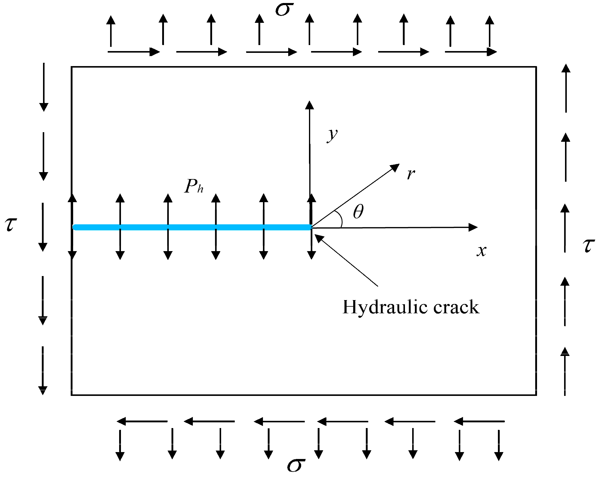
2.1. Derivation of New Stress Function for Hydro-Mechanical Coupling Cracks

Figure 1 shows an infinite plate with a crack under a uniform hydraulic pressure Ph on the crack surface, where a rectangular coordinate (xoy) and a polar coordinate (roθ; anti-clockwise θ is defined as positive) are set at the right tip of the crack with the X-axis along the direction of the original crack surface.
According to Williams expansion, the common stress fields at the crack tip of a polar coordinate system are expressed as follows:
σ r = λ r λ 1 λ + 1 A sin λ + 1 θ + B cos λ + 1 θ + λ 3 C i n λ 1 θ + D cos λ 1 θ σ θ = λ λ + 1 r λ 1 A sin λ + 1 θ + B cos λ + 1 θ + C sin λ 1 θ + D cos λ 1 θ τ r θ = λ r λ 1 λ + 1 A cos λ + 1 θ B sin λ + 1 θ + λ 1 C cos λ 1 θ D sin λ 1 θ
where A, B, C, and D are undetermined weight functions, and λ is the crack-tip singularity index.
For single material cracks, the singularity index is usually taken as λ = 0.5. In this case, by substituting θ = π and θ = −π into the second term of Equation (1), the following can be obtained:
σ θ θ = π = 3 4 r A C σ θ θ = π = 3 4 r A + C
However, the boundary condition σ θ θ = π = σ θ θ = π = Ph is required under hydraulic pressure Ph. Obviously, the crack-tip stress function under hydro-mechanical coupling needs to be modified due to the fact that Equation (2) cannot satisfy this boundary condition.
Assuming a new stress function F(r, θ, Ph), its relationship with the stress field and displacement field needs to be satisfied:
σ r = 1 r 2 𝜕 2 F r , θ , P h 𝜕 θ 2 + 1 r 𝜕 F r , θ , P h 𝜕 r σ θ = 𝜕 2 F r , θ , P h 𝜕 r 2 τ r θ = 𝜕 𝜕 r 1 r 𝜕 F r , θ , P h 𝜕 θ
2 G u r = 𝜕 F r , θ , P h 𝜕 r + 1 υ 1 + υ r 𝜕 ψ 1 𝜕 θ 2 G u θ = 1 r 𝜕 F r , θ , P h 𝜕 θ + 1 υ 1 + υ r 2 𝜕 ψ 1 𝜕 r
where G is the shearing modulus, υ is Poisson’s ratio, and the relationship between F(r, θ, Ph) and ψ1 can be defined as follows:
2 F r , θ , P h = 𝜕 𝜕 r 𝜕 ψ 1 𝜕 θ
The stress function F(r, θ, Ph) must satisfy the biharmonic equation:
2 2 F r , θ , P h = 0
To make the stress field in Equation (3) satisfy the hydro-mechanical coupling crack boundary condition,
σ θ θ = π = P h ,     σ θ θ = π = P h τ r θ θ = π = 0 ,     τ r θ θ = π = 0
The expression for a new hydro-mechanical coupling crack tip F(r, θ, Ph) can be obtained by substituting Equation (7) into Equations (3) and (4) and integrating to solve, as follows:
F r , θ , P h = r λ + 1 A sin λ + 1 θ + B cos λ + 1 θ + C sin λ 1 θ + D cos λ 1 θ + r λ + 1 P h 2

2.2. Determination of Weight Function and Semi-Weight Function for Hydro-Mechanical Coupling Crack

According to the derivation of the new hydro-mechanical coupling stress function F(r, θ, Ph) in Section 2.1, the corresponding stress and displacement fields are shown as follows:
σ r = λ r λ 1 λ + 1 A sin λ + 1 θ + B cos λ + 1 θ + λ 3 C i n λ 1 θ + D cos λ 1 θ + P h σ θ = λ λ + 1 r λ 1 A sin λ + 1 θ + B cos λ + 1 θ + C sin λ 1 θ + D cos λ 1 θ + P h τ r θ = λ r λ 1 λ + 1 A cos λ + 1 θ B sin λ + 1 θ + λ 1 C cos λ 1 θ D sin λ 1 θ u r = r λ λ + 1 A sin λ + 1 θ + B cos λ + 1 θ + λ κ C sin λ 1 θ + D cos λ 1 θ / 2 G + λ + 1 1 + κ + κ 3 λ P h r / 16 G λ u θ = r λ λ + 1 A cos λ + 1 θ B sin λ + 1 θ + λ + κ C cos λ 1 θ D sin λ 1 θ / 2 G
where
κ = 3 4 υ ( 3 υ ) / ( 1 + υ ) for   plane   strain for   plane   stress
The stress in Equation (9) also satisfies the boundary conditions. By substituting Equation (9) into Equation (3), the following can be obtained:
A sin λ + 1 π + B cos λ + 1 π + C sin λ 1 π + D cos λ 1 π = 0 λ + 1 A cos λ + 1 π B sin λ + 1 π + λ 1 C cos λ 1 π D sin λ 1 π = 0 A sin λ + 1 π + B cos λ + 1 π C sin λ 1 π + D cos λ 1 π = 0 λ + 1 A cos λ + 1 π + B sin λ + 1 π + λ 1 C cos λ 1 π + D sin λ 1 π = 0
In order to solve the undetermined weight function (A, B, C, and D), the sub-matrix method is used [25]. First, by rewriting Equation (9) into a matrix form, the following can be obtained:
      N 1 S C D = N 2 S A B N 1 T S T C D = N 2 T S T A B
where Ni (i = 1, 2), S, and T are second-order coefficient matrices, and their definitions are as follows:
N 1 = 1 0 0 λ 1         N 2 = 1 0 0 λ + 1 S = sin λ π cos λ π cos λ π sin λ π         T = 1 0 0 1
Then, by selecting {A, B}T as the basic undetermined weight function and combining the two equations in Equation (12), the following can be calculated:
N 1 T S T S 1 N 1 1 N 2 S + N 2 T S T A B = 0
To calculate the non-zero solutions of the basic undetermined weight function (A and B), the determinant for the coefficient matrix of Equation (14) must satisfy the condition of being equal to 0, as follows:
4 sin 2 λ π 2 = 0
Obviously, Equation (15) is the characteristic equation fused to solve the singularity index (λ) of the crack tip.
Finally, according to the definition of the stress-intensity factor, there are
K 1 = lim r 0 ( r 1 λ σ θ θ = 0 ) ,   K 2 = lim r 0 ( r 1 λ τ r θ θ = 0 )
Thus, the basic weight functions A and B can be obtained by substituting Equations (9) and (12) into Equation (16):
A = K 2 ,     B = K 1 3
and {C, D}T can be solved using Equation (12).
Similar to the weight function (A, B, C, and D), the key to calculating the semi-weighted function (A′, B′, C′, and D′) is to replace −λ with λ in Equation (8) to obtain the corresponding stress field and displacement field, as follows:
σ r = λ r λ 1 [ ( λ 1 ) ( A s i n ( λ 1 ) θ B c o s ( λ 1 ) θ ) + ( λ + 3 ) ( C s i n ( λ + 1 ) θ D c o s ( λ + 1 ) θ ) ] + P h σ θ = λ ( λ 1 ) r λ 1 [ A s i n ( λ 1 ) θ B c o s ( λ 1 ) θ + C s i n ( λ + 1 ) θ D c o s ( λ + 1 ) θ ] + P h τ r θ = λ r λ 1 [ ( λ 1 ) ( A cos ( λ 1 ) θ + B sin ( λ 1 ) θ ) + ( λ + 1 ) ( C cos ( λ + 1 ) θ + D sin ( λ + 1 ) θ ) ] u r = r λ [ λ 1 A s i n λ 1 θ B c o s λ 1 θ + λ + κ C s i n λ + 1 θ D c o s λ + 1 θ ] / 2 G u θ = r λ [ λ 1 A cos λ 1 θ + B sin λ 1 θ + λ κ C cos λ + 1 θ + D sin λ + 1 θ ] / 2 G
The boundary conditions (Equation (7)) are also satisfied by the stresses in Equation (18) and can be expressed in a matrix form:
      N 2 S C D = N 1 S A B N 2 S C D = N 1 S A B S = S T ,     S = T S
By substituting Equation (19) into the stress-intensity factor definition formula, the following can be obtained:
A 1 = Q 2 ,     B 1 = 3   Q 1
where Q1 and Q2 are arbitrary real numbers, meaning the SIFs in a semi-weight function.

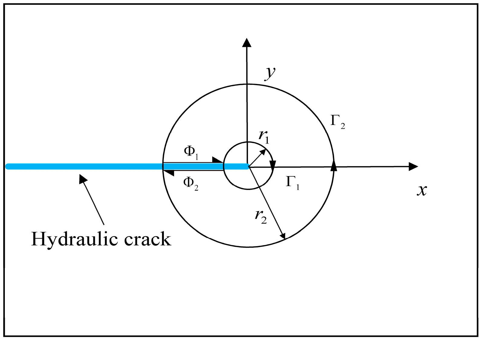
2.3. Calculation of Hydro-Mechanical Coupling Stress-Intensity Factors

To calculate hydro-mechanical coupling SIFs (Figure 2) using the modified semi-weight function method, an arbitrary closed region Ω for the reciprocal theorem should be selected that contains the crack surface (Φ1 and Φ2) and internal and external circles Γ1 and Γ2 (with the same center of coordinate origin and radii r1 and r2).
Since the existing modified semi-weight function method is applicable mainly to free surface conditions (p = 0 and p′ = 0 on the integration paths Φ1 and Φ2), the reciprocal theorem for the work integral formula can be simplified as follows:
Γ 1 p i u i p i u i d s = Γ 2 p i u i p i u i d s
where p and u and p′ and u′ are the stress and displacement expressed by the weight function (without superscript “ ′ ”) and the semi-weight function (with superscript “ ′ ”), respectively.
It can be seen that Equation (21) does not adhere to the case of hydro-mechanical coupling loading cracks (p ≠ 0, p′ ≠ 0 and the path integrals on Φ1 and Φ2 cannot be neglected). Therefore, Equation (21) needs to be extended and expressed in a polar coordinate form, which can be obtained as follows:
Γ 1 ( σ r u r + τ r θ u θ σ r u r τ r θ u θ ) d s + Φ 1 + Φ 2 ( σ θ u θ + τ r θ u r σ θ u θ τ r θ u r ) d s = Γ 2 ( σ r u r + τ r θ u θ σ r u r τ r θ u θ ) d s
For the left side of Equation (22) (i.e., integral path Γ1, Φ1, and Φ2), by substituting σ r , σ θ , τ r θ , u r , and u θ , represented by the semi-weight function, and σr, σθ, τ, ur, and uθ, represented by the weight function, the following can be obtained:
Γ 1 ( σ r u r + τ r θ u θ σ r u r τ r θ u θ ) d s + Φ 1 + Φ 2 ( σ θ u θ + τ r θ u r σ θ u θ τ r θ u r ) d s = δ 1 Q 1 K 1 + δ 2 Q 2 K 2 + δ 3 K 1 P h r 2 1.5 + δ 4 Q 1 P h r 2 0.5
where δi (i = 1, 2, 3, 4) represents the integration coefficients related to the material parameter (G, κ); Ph is the hydraulic pressure of the crack surface; and r2 is the radius of the external integrate path Γ2.
The calculation of the undetermined SIFs can be simplified by arbitrarily selecting two groups with different Q1 and Q2:
Q 1 = 1 δ 1 Q 2 = 0   and   Q 1 = 0 Q 2 = 1 δ 2
For the right side of Equation (22) (i.e., integral path Γ2), substitute two groups of σ r , σ θ , τ r θ , u r , and u θ , represented by the semi-weight function (determined using Equations (18) and (24)), and σr, τ, ur, and uθ, determined by finite element calculation, and calculate in combination with Equation (23) to solve hydro-mechanical coupling SIFs (K1 and K2):
K 1 + δ 3 K 1 P h r 2 1.5 + δ 4 δ 1 P h r 2 0.5 = Γ 2 ( σ r , 1 u r + τ r θ , 1 u θ σ r u r , 1 τ r θ u θ , 1 ) d s K 2 + δ 3 K 1 P h r 2 1.5 = Γ 2 ( σ r , 2 u r + τ r θ , 2 u θ σ r u r , 2 τ r θ u θ , 2 ) d s
where the subscripts “ ,1 ” and “ ,2 ” correspond to two different groups of Q1 and Q2 (Equation (24)), respectively.
In summary, the detailed procedure used to solve the hydro-mechanical coupling SIFs by adopting the extended semi-weight function method is as follows:
(1) Substitute the material parameters (G, κ) into Equation (15) to obtain the stress field singularity (λ);
(2) Substitute λ into Equations (9), (12), (18) and (19) to solve Equation (22);
(3) Calculate σ r , σ θ , τ r θ , u r , and u θ in terms of the semi-weight functions by combining Equations (18) and (24), and the σr, τ, ur, and uθ obtained using finite element software for the right side of Equation (22);
(4) Substitute the stress and displacement fields determined by the semi-weight function and finite element results into Equation (25) to calculate the hydro-mechanical coupling SIFs.

3. Verification of the Extended Semi-Weight Function Method under Hydro-Mechanical Coupling

In this section, two different examples (one crack under hydro-mechanical coupling and arbitrary multi-cracks under hydro-mechanical coupling) are selected to demonstrate the validity of the new semi-analytic method and its applicability to multi-crack problems.

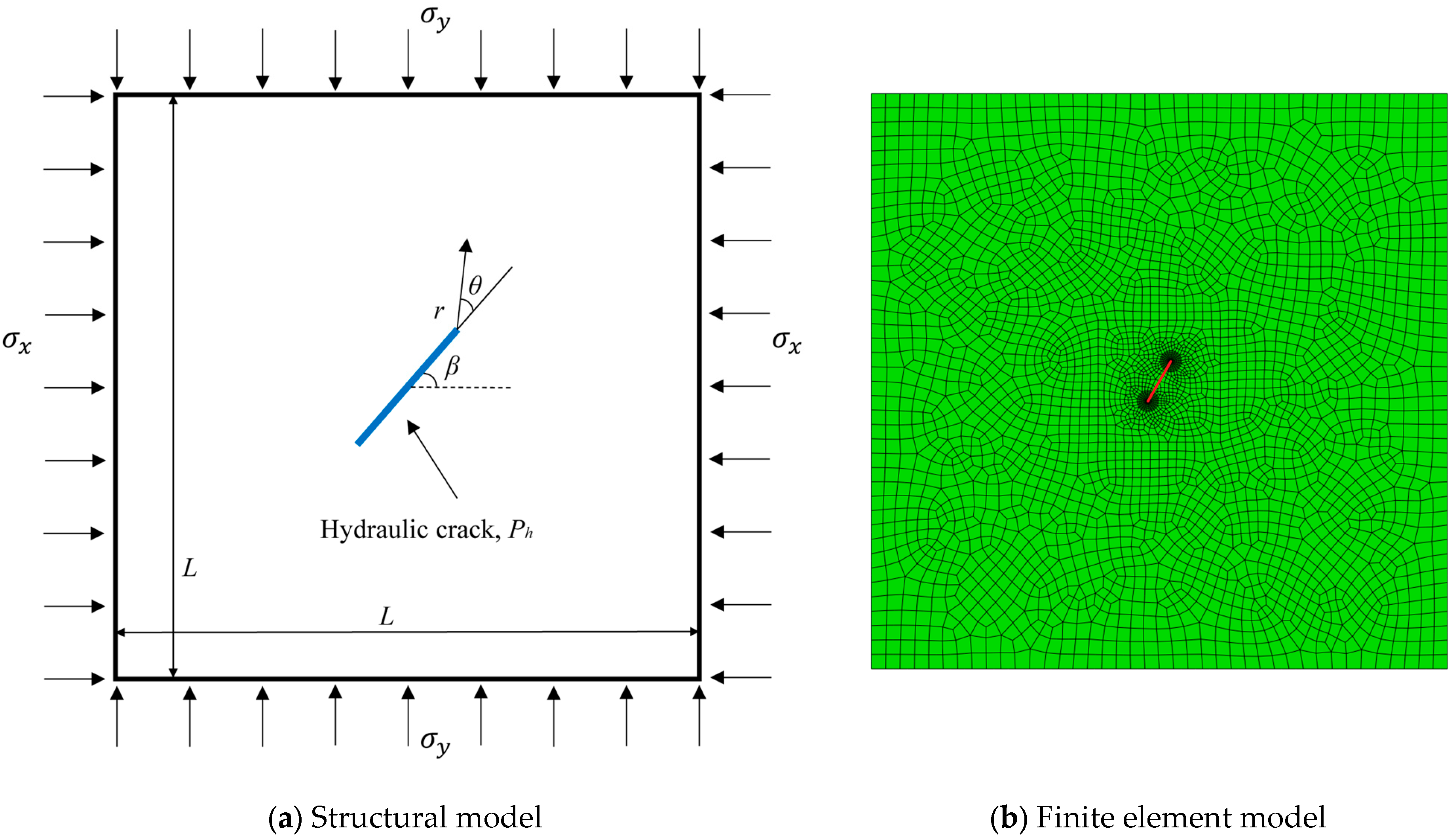
3.1. Example 1 (One Crack under Hydro-Mechanical Coupling)

Figure 3a shows a square plate (L × L = 200 m × 200 m) with a central inclined crack of length a (a = 16 m) under uniform hydraulic pressure (Ph = 12 MPa) and bi-directional pressure (σx = 6 MPa, σy = 12 MPa), where the angle between the crack and the X-axis is β (β = 0°, 20°, 40°, 60°, 80°, and 90°). To compare these results with those in the existing literature, let the elastic modulus be E = 6 GPa and Poisson’s ratio be υ = 0.2. Figure 3b shows the finite element model used to calculate the far-field of stress and displacement (Equation (25)).
Table 1 lists the calculation results of the hydro-mechanical coupling SIFs (K1) and the results in the existing literature obtained through the use of the analytical method [26] and the XFEM [17], respectively. It can be seen that the results of our new semi-analytical method are in good agreement with the results from the literature.

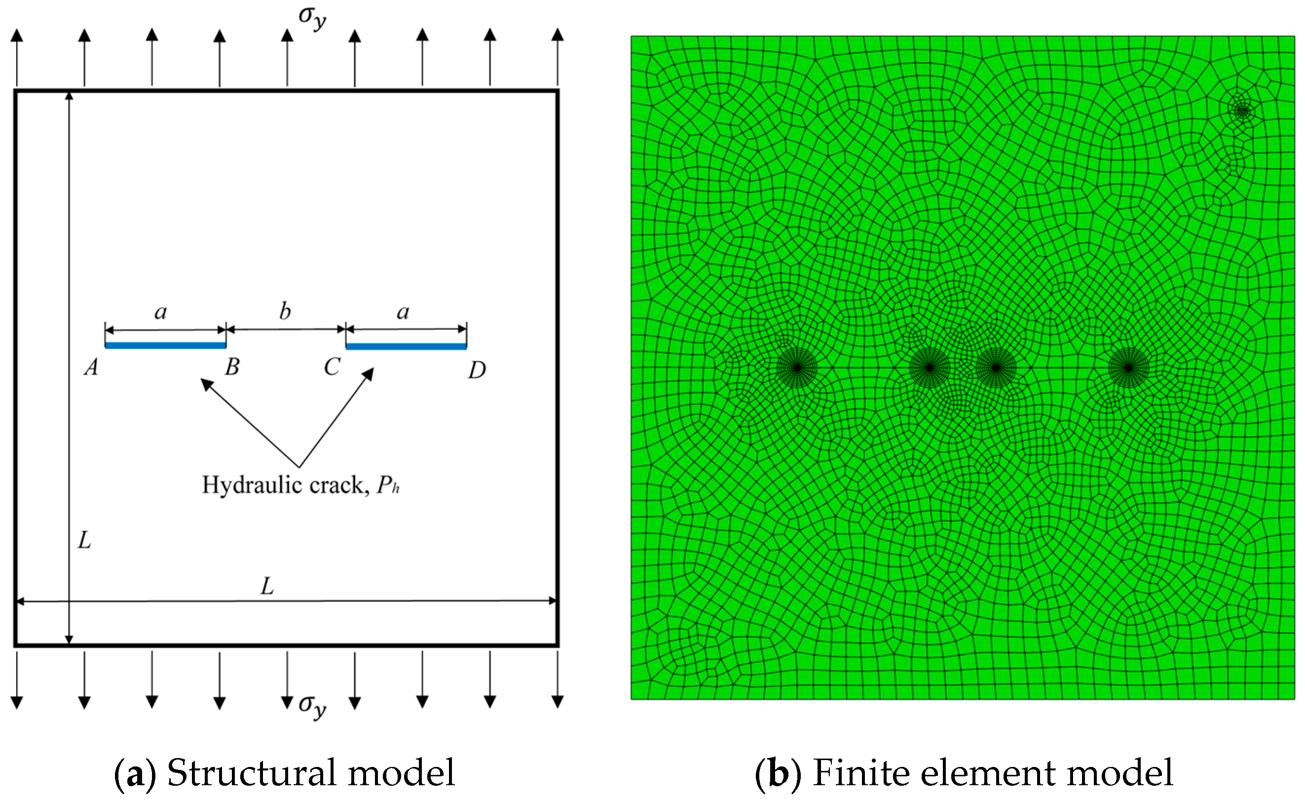
3.2. Example 2 (Arbitrary Multi-Cracks under Hydro-Mechanical Coupling)

For comparison with the calculation results available in the literature [19], Figure 4a shows a square plate (L × L = 150 mm × 150 mm) with two arbitrary cracks of length a (a = 30 mm) under a bi-directional pressure (σx = 6 MPa, σy = 10 MPa), where crack AB is subjected to a uniform hydraulic pressure (Ph = 1.3 MPa) and crack CD is a free crack. The material parameters are E = 9.08 GPa and υ = 0.29. Table 2 lists the relative horizontal (Dh) and vertical (Dv) distances between the midpoints of cracks AB and CD, the angle between crack AB and the X-axis (β), and the relative inclination angle between cracks AB and CD (α) for different calculation models. Figure 4b shows the finite element model used to calculate the far-field of stress and displacement (Equation (25)).
Table 3 lists the SIFs of a multi-crack under hydro-mechanical coupling as well as the results in the existing literature obtained via the complex function and superposition method [19]. It was also found that the SIFs calculated using our new semi-analytical method for the case of a multi-crack under hydro-mechanical coupling agree with those in the existing literature, which not only validates the effectiveness of the semi-analytical method but also demonstrates the advantage provided by the independence of our auxiliary function (semi-weight function and weight function) from structural parameters.

4. Results and Discussion

In order to study the factors that influence hydro-mechanical coupling SIFs, take a square plate with two horizontal co-linear cracks of length a and spacing b under hydro-mechanical coupling loading, with different radii of integral paths (r2) and loading conditions (σy and Ph).

4.1. Effect of Integral Paths

Since the new semi-analytic method contains an additional integration of the crack surface part (integral paths Φ1 and Φ2) compared to the modified semi-weight function method, it is necessary to investigate the effect of the integral paths on the calculation results.
Figure 5a shows a square plate (L × L = 100 mm × 100 mm) with a central co-linear double hydraulic crack of length a (a = 20 mm) and spacing b (b = a/2) under hydraulic pressure (Ph = 10 MPa) and far-field tensile stress (σy = 5 MPa); the material parameters are the same as those applied in Example 2. Figure 5b shows the corresponding finite element model, and Table 4 lists five groups of calculated SIFs (K1) for different external circular integral radii r2 (i.e., different integral lengths for integral paths Φ1 and Φ2 in Equation (23)).
It can be found that the K1 of the non-adjacent crack tip (point A) remains almost the same, while the K1 of the adjacent crack tip (point B) is almost unchanged in the range of r2 < b/2 and slightly increased in r2 > b/2. This is because when the external integral path Γ2 of point B is closer to the other crack tip (point C) in the range of r2 > b/2, the stress and displacement on the outer integral path are more affected by the singularities of the other crack tip (point C). Furthermore, point C has a greater effect on the SIFs of point B than that of point A, which is similar to the results available in the literature [25]. Therefore, to obtain more effective results, a reasonable range of the external integral radius (r2) for solving the multi-crack problem through the use of the extended semi-weight function method is r2 < b/2.

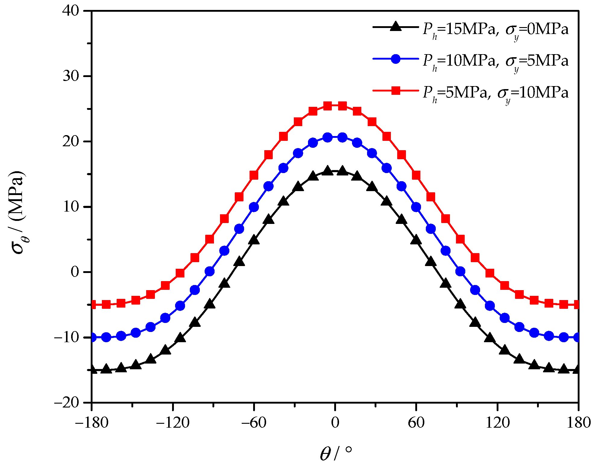
4.2. Effect of Loading Conditions

Considering that the stress field corresponding to the hydro-mechanical coupling stress function contains the related term of hydraulic pressure (Equation (9)), its effect on the calculation results of the SIFs and stress field needs to be investigated under different hydro-mechanical coupling loadings.
The calculation model used is the same as that described in Section 4.1, and three different groups of hydro-mechanical coupling loading conditions are given (Ph = 15 MPa, σy = 0 MPa; Ph = 10 MPa, σy = 5 MPa; Ph = 5 MPa, σy = 10 MPa). Table 5 and Figure 6 provide the calculated SIFs and stress component (σθ) for different loading conditions, respectively.
It can be seen that for this calculation model, when the sum of Ph and σy is constant, the SIF calculation results are similar regardless of the single values of Ph and σy. Furthermore, the same stress field can also be obtained by using the stress field definition of the common stress function [27] (Equation (26)) under different loading conditions.
σ θ = K 1 2 π r cos 3 θ 2 3 2 K 2 2 π r sin θ cos θ 2 τ r θ = 1 2 K 1 2 π r sin θ cos θ 2 + 1 2 K 2 2 π r cos θ 2 3 cos θ 1
Obviously, the stress fields of the crack tip calculated when using Equation (26) are inconsistent with the actual situation; moreover, they do not satisfy the hydraulic loading conditions at the crack surface (σθ is zero instead of Ph). On the contrary, when substituting the SIFs (Table 4) into the stress field defined by the hydro-mechanical coupling stress function (Equation (9)), it can be seen that there are significant differences in the magnitude of stress components under different loading conditions (Figure 6), and the boundary conditions can be satisfied. Therefore, more effective stress field results can be obtained by adopting our hydro-mechanical coupling stress function in the case of hydro-mechanical coupling loading.

5. Conclusions

(1) An extended semi-weight function method for calculating the hydro-mechanical coupling SIFs of arbitrary multi-cracks has been proposed by deriving the new hydro-mechanical coupling stress function and the extended reciprocal theorem of the working integral formula (suitable for arbitrary loads on crack surfaces), which has been subsequently verified via comparison with the results available in the literature.
(2) Compared with the existing methods, the extended semi-weight function method has the advantages of a uniform auxiliary function form, providing a simple solution. Furthermore, a more effective crack-tip stress field can be calculated (the normal stress at the crack face is equal to the hydraulic pressure) when using the new hydro-mechanical coupling stress function than can be obtained using the current methods (the normal stress at the crack face is equal to zero).
(3) For hydraulic multi-cracks, the SIFs of adjacent crack tips (i.e., crack tips that are closer to other cracks) are more affected by the external integral path compared to non-adjacent crack tips (i.e., crack tips that are further away from other cracks) due to the smaller distance of the external integral path from other crack tips. For the case of a = 3 mm (crack length) and b = 1.5 mm (cracks spacing), the SIFs of adjacent crack tips and non-adjacent crack tips are almost unchanged in the range of r2 < 0.75 mm, and the reasonable range of r2 is r2 < 0.75 mm when obtaining effective stress-intensity factors using the extended semi-weight function method.
(4) For cases where the hydraulic pressure (Ph) is in the same direction as the far-field stress (σy), there is no significant difference in the SIFs at the crack tip regardless of the single value of Ph and σy when their sum is constant. However, the stress components (σθ) at r = 0.25 mm calculated using the extended semi-weight function method are 15.79 MPa, 20.83 MPa, and 25.78 MPa under Ph = 15 MPa and σy = 0 MPa, Ph = 10 MPa and σy = 5 MPa, Ph = 5 MPa and σy = 10 MPa, respectively (the stress field obtained by the common stress function is the same), which are more consistent with the actual situation.

Author Contributions

L.Z. (Lan Zhang): data curation, methodology, software, validation, and writing—original draft. D.-y.H.: methodology, conceptualization, writing—review and editing, and supervision. L.Z. (Lei Zhang): writing—review and editing. C.L.: validation. H.Q.: software. All authors have read and agreed to the published version of the manuscript.

Funding

This work was supported by the Water Resources and Technology Program of Hunan Province (XSKJ2022068-30).

Data Availability Statement

All data used during this study are available from the corresponding author upon request.

Conflicts of Interest

The authors declare that they have no known competing financial interest or personal relationships that could have appeared to influence the work reported in this paper.

References

  1. Wang, Y.; Jia, J.S. Experimental study on the influence of hydraulic fracturing on high concrete gravity dams. Eng. Struct. 2017, 13, 2508–2517. [Google Scholar] [CrossRef]
  2. Zhou, Y.F.; Su, K.; Wu, H.G. Hydro-mechanical interaction analysis of high pressure hydraulic tunnel. Tunn. Undergr. Space Technol 2015, 47, 28–34. [Google Scholar] [CrossRef]
  3. Yi, W.; Rao, Q.H.; Sun, D.L.; Shen, Q.Q.; Zhang, J. A new integral equation method for calculating interacting stress-intensity factors of multiple holed-cracked anisotropic rock under both far-field and arbitrary surface stresses. Int. J. Rock Mech. Min. Sci. 2021, 148, 104926. [Google Scholar] [CrossRef]
  4. Cheng, Y.X.; Zhang, Y.J.; Yu, Z.W.; Hu, Z.J. Investigation on reservoir stimulation characteristics in hot dry rock geothermal formations of china during hydraulic fracturing. Rock Mech. Rock Eng. 2021, 54, 3817–38452. [Google Scholar] [CrossRef]
  5. Cui, Z.D.; Liu, D.A.; Zeng, R.S.; Niu, J.R.; Wang, H.J.; Shi, X.S. Resistance of caprock to hydraulic fracturing due to CO2 injection into sand lens reservoirs. Eng. Geol. 2013, 164, 146–154. [Google Scholar] [CrossRef]
  6. Chen, W.H.; Chang, C.S. Analysis of multiple cracks in an infinite plate under arbitrary crack surface tractions. Arch. Appl. Mech. 1990, 60, 202–212. [Google Scholar] [CrossRef]
  7. Niu, J.; Wu, M.S. Analysis of Asymmetric Kinked Cracks of Arbitrary Size, Location and Orientation—Part I. Remote Compression. Int. J. Fract. 1998, 89, 19–57. [Google Scholar] [CrossRef]
  8. Rohde, L.; Kienzler, R.; Herrmann, G. On a new method for calculating stress-intensity factors of multiple edge cracks. Philos. Mag. 2005, 85, 4231–4244. [Google Scholar] [CrossRef]
  9. Wang, N.; Atluri, L.H. An implementation of the Schwartz-Neumann Alternating Method for collinear multiple cracks with mixed type of boundary conditions. Comput. Mech. 1995, 16, 266–271. [Google Scholar] [CrossRef]
  10. Hejazi, A.A.; Ayatollahi, M.; Bagheri, R.; Monfared, M.M. Dislocation technique to obtain the dynamic stress intensity factors for multiple cracks in a half-plane under impact load. Arch. Appl. Mech. 2014, 84, 95–107. [Google Scholar] [CrossRef]
  11. Kachanov, M. Elastic solids with many cracks: A simple method of analysis. Int. J. Solids Struct. Comput. Mech. 1987, 23, 23–43. [Google Scholar] [CrossRef]
  12. Gorbatikh, L.; Lomov, S.; Verpoest, I. On Stress Intensity Factors of Multiple Cracks at Small Distances in 2-D Problems. Int. J. Fract. 2007, 143, 377–384. [Google Scholar] [CrossRef]
  13. Sapora, A.; Spagnoli, A.; Susmel, L.; Cornetti, P. A simplified approach to hydraulic fracturing of rocks based on Finite Fracture Mechanics. Fatigue Fract. Eng. Mater. Struct. 2023, 46, 3029–3042. [Google Scholar] [CrossRef]
  14. Zhang, G.; Li, X.; Li, H. Simulation of hydraulic fracture utilizing numerical manifold method. Sci. China Technol. Sci. 2015, 58, 1542–1557. [Google Scholar] [CrossRef]
  15. Zhao, Y.L.; Cao, P.; Wang, W.J.; Wan, W.; Chen, R. Wing crack model subjected to high hydraulic pressure and far field stresses and its numerical simulation. J. Cent. South Univ. 2012, 19, 578–585. [Google Scholar] [CrossRef]
  16. Wu, H.; Settgast, R.R.; Fu, P.; Morris, J.P. An Enhanced Virtual Crack Closure Technique for Stress Intensity Factor Calculation along Arbitrary Crack Fronts and the Application in Hydraulic Fracturing Simulation. Rock Mech. Rock Eng. 2021, 54, 2943–2957. [Google Scholar] [CrossRef]
  17. Cheng, L.; Luo, Z.; Yu, Y.; Zhao, L.Q.; Zhou, C.L. Study on the interaction mechanism between hydraulic fracture and natural karst cave with the extended finite element method. Eng. Fract. Mech. 2019, 222, 106680. [Google Scholar] [CrossRef]
  18. Yi, W.; Rao, Q.H.; Luo, S.; Shen, Q.Q.; Li, Z. A New Integral Equation Method for Calculating Interacting Stress Intensity Factor of Multiple Crack-hole Problem. Theor. Appl. Fract. Mech. 2020, 107, 102535. [Google Scholar] [CrossRef]
  19. Shen, Q.Q.; Rao, Q.H.; Sun, D.L.; Yi, W.; Huang, D.Y.; Li, Z. A new optimization method of double-crack distributions for improving network fracture conductivity of natural gas exploitation. Theor. Appl. Fract. Mech. 2022, 122, 103655. [Google Scholar] [CrossRef]
  20. Chang, J.H.; Wu, D.J. Calculation of mixed-mode stress intensity factors for a crack normal to a bimaterial interface using contour integrals. Eng. Fract. Mech. 2003, 70, 1675–1695. [Google Scholar] [CrossRef]
  21. Ševeček, O.; Kotoul, M.; Profant, T.; Hrstka, M. Crack kinking out of interface of two orthotropic materials under combined thermal/mechanical loading. Theor. Appl. Fract. Mech. 2020, 105, 102397. [Google Scholar] [CrossRef]
  22. Huang, D.Y.; Ma, Y.; Rao, Q.H.; Yi, W.; Shen, K. A new semi-analytic method for calculating the thermal–mechanical coupling stress intensity factor of interfacial crack. Theor. Appl. Fract. Mech. 2023, 128, 104156. [Google Scholar] [CrossRef]
  23. Karlsson, A.; Bäcklund, J. J-integral at loaded crack surfaces. Int. J. Fract. 1978, 14, R311–R318. [Google Scholar] [CrossRef]
  24. Song, H.; Rahman, S.S. An extended J-integral for evaluating fluid-driven cracks in hydraulic fracturing. J. Rock Mech. Geotech. Eng. 2018, 10, 832–843. [Google Scholar] [CrossRef]
  25. Huang, D.Y.; Rao, Q.H.; Ma, Y.; Yi, W.; Shen, Q.Q. A modified semi-weight function method for stress intensity factor calculation of a vertical crack terminating at the interface. Theor. Appl. Fract. Mech. 2021, 116, 103107. [Google Scholar] [CrossRef]
  26. Rice, J.R. Mathematical analysis in the mechanics of fracture. Fract. Adv. Treatise 1968, 2, 191–311. [Google Scholar]
  27. Bahrami, B.; Nejati, M.; Ayatollahi, M.R.; Driesner, T. Theory and experiment on true mode II fracturing of rocks. Eng. Fract. Mech. 2020, 240, 107314. [Google Scholar] [CrossRef]
Figure 1. Calculation model of hydro-mechanical coupling stress function.
Applsci 14 07083 g001
Figure 2. Integral path.
Applsci 14 07083 g002
Figure 3. Calculation model of Example 1.
Applsci 14 07083 g003
Figure 4. Calculation model of Example 2.
Applsci 14 07083 g004
Figure 5. Calculation model.
Applsci 14 07083 g005
Figure 6. The stress component (σθ) for different loading conditions at r = b/6.
Applsci 14 07083 g006
Table 1. Calculation results of hydro-mechanical coupling SIFs (K1) via different methods.
βAnalytical Method [26]XFEM [17]Present
30.077330.079530.1446
20°27.730227.733827.9503
40°21.793821.794121.9319
60°15.038615.039815.1547
80°10.634510.637110.8092
90°10.021810.026510.1654
Table 2. Structural parameters for different calculation models.
No.Dh (mm)Dv (mm)α (°)β (°)
11040855
21040505
31030855
Table 3. Calculation results of hydro-mechanical coupling SIFs via different methods.
PointABCD
No.1
Shen [19]K1 (MPa·mm0.5)−59.76−60.83−43.09−41.95
K2 (MPa·mm0.5)−3.19−4.223.18−3.90
PresentK1 (MPa·mm0.5)−60.24−61.51−43.7−42.13
K2 (MPa·mm0.5)−3.23−4.323.11−3.79
No.2
Shen [19]K1 (MPa·mm0.5)−57.21−58.38−54.82−48.94
K2 (MPa·mm0.5)−1.02−6.2711.3613.19
PresentK1 (MPa·mm0.5)−58.17−58.99−55.25−49.73
K2 (MPa·m0.5)−0.97−6.0711.4813.30
No.3
Shen [19]K1 (MPa·mm0.5)−59.65−65.14−43.36−40.86
K2 (MPa·mm0.5)−1.35−3.39−1.43−9.82
PresentK1 (MPa·mm0.5)−60.13−65.72−44.11−41.68
K2 (MPa·mm0.5)−1.27−3.28−1.27−9.55
Table 4. Hydro-mechanical coupling SIFs (K1) for different external integral radii (r2).
b/6b/3b/22b/35b/6
Point A92.15192.15392.15092.15292.152
Point B99.25999.25799.260100.924101.812
Table 5. Hydro-mechanical coupling SIFs (K1) for different loading conditions.
Ph = 15 MPa
σy = 0 MPa
Ph = 10 MPa
σy = 5 MPa
Ph = 5 MPa
σy = 10 MPa
Point A92.15192.15192.150
Point B99.30199.25999.224
Disclaimer/Publisher’s Note: The statements, opinions and data contained in all publications are solely those of the individual author(s) and contributor(s) and not of MDPI and/or the editor(s). MDPI and/or the editor(s) disclaim responsibility for any injury to people or property resulting from any ideas, methods, instructions or products referred to in the content.

