Abstract
This paper studied the tribological behaviour of parts manufactured using fused filament fabrication (FFF) technology with PETG (polyethylene terephthalate glycol) coated with IGUS tribological filaments. The research focuses on analysing how these multi-material parts behave under different loads. The objective of this study is to evaluate the wear resistance and friction coefficient of parts coated with different thicknesses of IGUS material. The methodology employs pin-on-disc (PoD) tribological tests to measure behaviour under various load conditions and coating thicknesses. The results indicate that increasing the coating thickness improves surface stability and reduces roughness, although it does not significantly affect the average friction coefficient. This research concludes that coating thickness has a moderate impact on surface quality and that the applied load significantly influences the depth and width of the wear groove. This contribution is valuable for the field of additive manufacturing as it provides a better understanding of how to optimise the tribological properties of parts manufactured using FFF, which is crucial for industrial applications where wear and friction are critical factors. The practical application includes the potential improvement of components in the automotive and aerospace industries.
1. Introduction
Additive manufacturing (AM) has transformed the way products are produced in various industrial fields. This process involves creating products from digital models by depositing material layer by layer until the complete three-dimensional part is formed. Additive manufacturing offers several significant advantages over traditional manufacturing methods, including the ability to produce complex geometries, reduce material waste, and allow for greater customisation of products [1]. However, due to the rapid expansion of the technique, there are still many areas where sufficient knowledge does not exist.
Among the most prominent additive manufacturing (AM) technologies is fused deposition modeling (FDM), also known as fused filament fabrication (FFF). FFF belongs to the material extrusion MEX family according to ISO/ASTM 52900:2021 standards [2]. FFF employs thermoplastic filaments that are extruded through a heated nozzle and deposited following a specific pattern programmed by software to create a solid part. This process is highly versatile and permits the use of a wide range of materials, from common plastics to advanced composites [1]. FFF is particularly popular due to its ability to produce high-precision and durable parts at low cost. Its accessibility has allowed this technology to be adopted by both large manufacturing companies and small businesses due to its ease of implementation and low learning curve [3].
This rapid implementation is also due to its ability to produce functional parts. This is a significant industrial advantage as it allows for rapid customisation of designs, reducing the time and costs associated with developing new products. Therefore, FFF is ideal for producing short and customised runs as it does not require expensive moulds or specific tools [4].
Additionally, the properties of the resulting parts can be controlled, although they largely depend on the printing process parameters. Optimising part orientation, fill density and pattern, layer height, and extruder temperature can result in significant improvements in the strength and stiffness of printed parts. The ability to adjust these parameters offers considerable flexibility to tailor the mechanical properties of FFF parts to the specific needs of various applications.
Thus, parts printed in an orientation with +45°/−45° fill angles have shown higher tensile and impact strength compared to other orientations. This finding is significant because the print orientation can be optimised to enhance mechanical properties based on specific application needs [5].
On the other hand, another crucial variable is the fill density. It has been shown that a higher fill density generally results in higher mechanical strength. For example, an 80% fill density has been shown to significantly improve the tensile and flexural properties of printed parts. The choice of fill pattern is also influential, with more uniform patterns providing better results in terms of stress distribution and deformation [6].
Layer height is another parameter that affects the mechanical properties of FFF parts. Thinner layers tend to improve dimensional accuracy and mechanical strength due to better layer adhesion. However, printing with thinner layers increases printing time, which can be a limitation in the rapid manufacturing processes [7]. Additionally, extruder temperature and print speed also play significant roles. Optimal extruder temperature ensures proper material fusion, contributing to better layer bonding and, consequently, higher mechanical strength. On the other hand, an appropriate print speed is necessary to maintain a balance between print quality and the mechanical integrity of the part [8].
However, most studies address static mechanical properties but the dynamics of the parts are vital for their industrial implementation. Among these properties is the fatigue resistance of FFF parts, which is an important consideration for structural applications [9]. However, few studies address the tribological behaviour of FFF parts, although it is an area of study that is gaining attention [10,11]. This may be due to the inherent roughness of additive processes conditioning this tribological behaviour, making its study especially complex. Although the limited existing information generally shows that FFF parts exhibit higher friction coefficients and wear rates due to the inherent roughness of surfaces fabricated by this process [12].
This is important as it may mean that manufacturing parameters such as layer thickness, fill pattern, and fill density have a significant impact on the wear rate and friction coefficient. Thus, it has been observed that a greater layer thickness contributes to higher wear resistance due to the greater amount of material that must be worn down to reach the substrate [13]. Print orientation also plays a crucial role in the tribological properties of 3D-printed parts. Parts printed in vertical orientations tend to have less wear depth, but higher friction coefficients compared to parts printed in other orientations [14]. However, other parameters are tremendously relevant, such as the nature of the materials themselves, and this is another advantage of FFF as it is possible to use advanced materials such as reinforced and composite filaments that offer improved mechanical and thermal properties. These materials allow for the creation of parts that can withstand extreme use conditions, further expanding the applications of this technology [15].
The basic materials within FFF are ABS (acrylonitrile butadiene styrene) and mainly PLA (polylactic acid) for its ease of manufacture [16]. These materials have shown that ABS parts have better tribological properties compared to PLA. Additionally, adding carbon fibers to PLA has shown improvements in wear resistance and reduced friction coefficient [17]. However, other materials like PETG (polyethylene terephthalate glycol) offer excellent tribological performance [10]. This material is highly resistant to impacts and chemicals, making it an ideal tool for use in industrial environments. PETG is also known for its excellent layer adhesion during the printing process, allowing for the fabrication of parts with high structural integrity and wear resistance. Furthermore, its recyclability and low moisture absorption make it a sustainable and practical material for various applications. Compared to PLA and ABS, despite these materials having high strength [18,19], PETG has a higher load capacity and elongation [20,21]. Additionally, although PLA is a biodegradable material, PETG is easily reusable. Moreover, there are other special materials, like those developed by IGUS for better tribological performance.
IGUS materials are used in components that must withstand continuous movement, such as bearings, linear guides, and gears. IGUS tribological filaments are formulated with self-lubricating polymers that significantly reduce the need for maintenance, improve efficiency, and prolong the life of printed parts. Among their products in this field are filaments for FFF designed to operate without additional lubrication that offer excellent wear resistance, even under adverse conditions [22]. Using these materials in the FFF process not only facilitates the creation of customised parts but also allows for superior tribological characteristics. IGUS filaments can be used as easily as other thermoplastics but offer the additional advantage of improving the friction and wear properties of the resulting parts [22]. This is particularly useful in applications where components are subject to constant movement and mechanical loads, such as in the automotive, aerospace, and machinery manufacturing industries [23,24].
This ability to use advanced materials significantly expands the scope and functionality of parts manufactured with FFF, providing effective and durable solutions for a wide range of mechanical and structural applications.
There is even the possibility of creating parts with dissimilar materials, which opens a new frontier in the use of FFF, taking advantage of an advantage that so far was only used to create support structures. Multi-material manufacturing enables the creation of parts that combine various properties in a single object, optimising mechanical performance and expanding design and functionality capabilities. This approach allows for the designing of components that leverage the unique characteristics of various materials to improve efficiency and durability [25,26,27]. Thus, it would be possible to create parts with mechanical performance optimised for their final application, even if it is a tribological application. However, this possibility is not yet industrially implemented.
Upon analysing this information, it is found that there are fewer studies related to the tribological behaviour of parts manufactured with FFF compared to other mechanical properties, such as tensile or compression, so much so that there is no established procedure for the characterisation of tribological behaviour due to the influence of a large number of involved parameters. This lack of knowledge is even more pronounced in more novel or specific materials. Additionally, there are no previous studies that analyse parts manufactured with different materials, dissimilar materials, or coated materials.
One of the great advantages of additive manufacturing is the ability to offer different properties to different zones of the parts depending on the material deposition and the type of material deposited. However, the high complexity of manufacturing parts with multiple materials using additive processes and the customisation of properties are not being exploited, especially for tribological purposes.
Therefore, this study presents a solution to a previously unstudied problem: the tribological behaviour of multi-material parts. This article presents the tribological study of parts made with a core of high mechanical strength and stability against environmental conditions, such as PETG, coated with IGUS filament to improve tribological conditions. The behaviour of these multi-material parts will be studied using a pin-on-disc test, analysing the load they can withstand against different coating thicknesses.
This approach allows for the evaluation of the feasibility of using specific coatings to optimise the tribological properties of parts manufactured via FFF, opening up new possibilities for industrial and customised applications.
2. Experimental Procedure
As explained, this study analyses the behaviour of multi-material parts manufactured with fused filament fabrication (FFF). Given that the objective of the study is not to develop a new material but to leverage the capabilities of existing commercial materials, in all cases, known materials with previously studied properties will be used, seeking a novel application for which no prior knowledge exists. Therefore, a commercial 1.75 mm diameter filament will be used, specifically, PETG and IGUS Iglidur I50 tribofilament, expressly developed for dynamic contact motion applications [22]. Circular specimens of 70 mm in diameter and 2 mm in thickness have been manufactured, with these materials using a commercial FFF equipment equipped with a 0.4 mm diameter extruder nozzle.
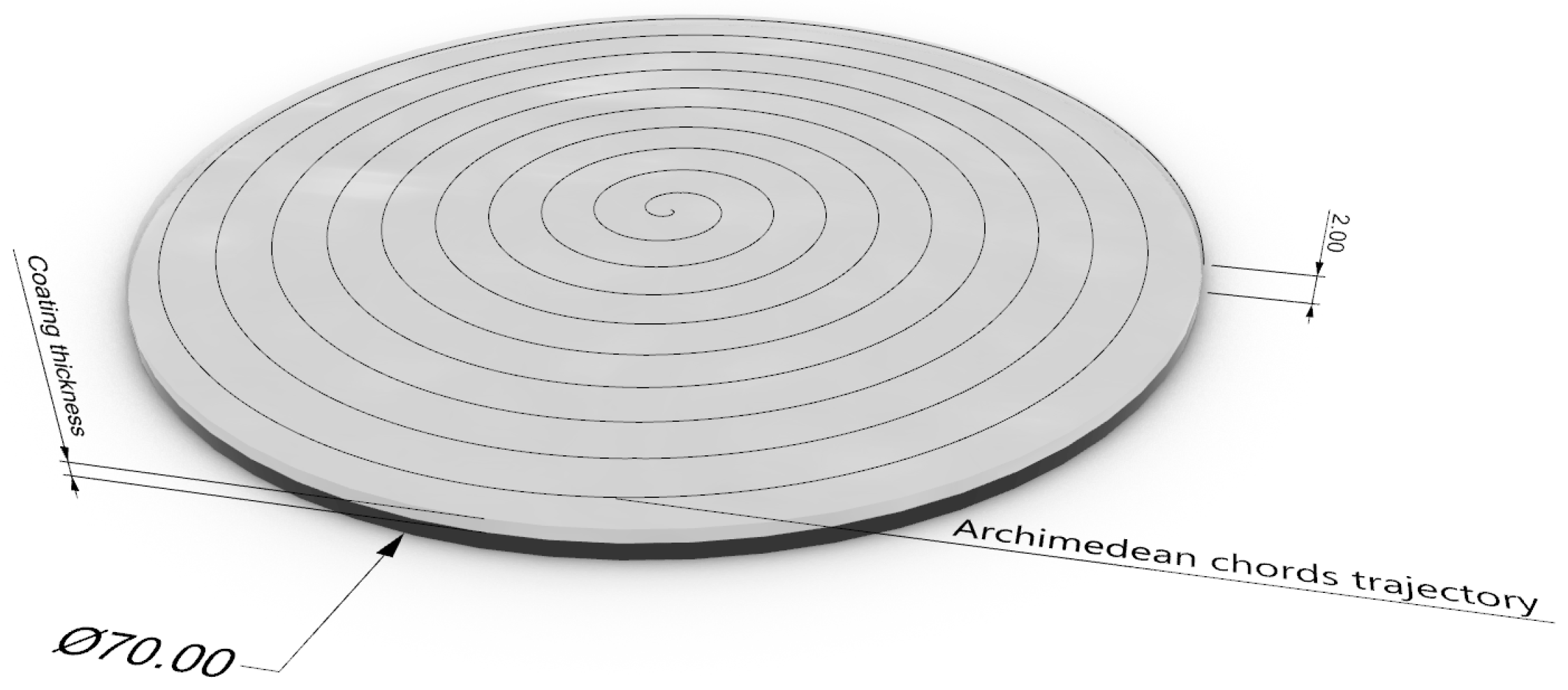
Within the manufacturing parameters, extrusion speed of 60 mm/s, a filament overlaps of 55%, a build platform temperature of 60 °C, and 100% fill have been established as constants. Additionally, Archimedean chords fill geometry has been used. This is to ensure that the material deposition direction is consistent with the sliding direction of the tribological tests. In this way, changes in the surface texture of the parts do not alter the tribological results. These parameters have been selected based on previous studies [10,11,28,29]. Figure 1 presents the scheme of the specimens and manufacturing strategies.

Figure 1.
Scheme of specimens and manufacturing strategies.
For multi-material manufacturing, two manufacturing phases have been programmed, with an intermediate stop for material change and manufacturing parameters. Thus, two extrusion temperatures have been used: first, PETG required 230 °C, while IGUS tribofilament required 250 °C. The manufacturing parameters are listed in Table 1. These parameters are those recommended by the filament manufacturers.

Table 1.
Materials and manufacturing parameters.
This programmed change was made to create an IGUS coating layer on PETG of a certain thickness. Since a layer thickness of 0.3 mm has been programmed for the entire specimen, this coating will be 0.3 mm (one-layer coating), 0.6 mm (two-layer coating), and 0.9 mm (three-layer coating). Prior to the manufacture of the specimens, a metrological calibration of the manufacturing equipment was carried out to guarantee the layer thicknesses deposited in each case.
Subsequently, the manufactured specimens were subjected to pin-on-disc (PoD) tribological tests following ASTM G99 standards [30] using a Microtest MT NI series equipment (Microtest, Madrid, Spain). Due to the lack of specific standards, this study used methodologies validated in previous studies [10,11], based on the general standards of the test [30]. In this way, for the performance of pin-on-disc tests, the linear test speed will be a constant 105 mm/s, and the total distance travelled by the pin will be 250 m. The testing parameters are listed in Table 2.
Table 2.
Materials and testing parameters.
Using the coefficient of friction (CoF) data obtained in the tests, the evolution of the test will be calculated by calculating a moving trend line and an average coefficient of friction value obtained as an arithmetic mean of the data obtained in the intermediate 150 m of each test. Similarly, the amplitude of the CoF will be calculated as the distance between the average of the three highest peaks and the three deepest valleys.
Additionally, all specimens will be analysed using stereoscopic optical microscopy before and after the tests, as well as the pins used and any detached particles or debris. For this, a Leica S9i optical microscope (Leica, Wetzlar, Germany) will be used. Moreover, following ISO 25178-2:2012 [31] and EUR 15178N [32] standards, the surface of the specimen will be analysed using a Variable Focus Microscope Bruker Alicona G5+ (Bruker, Chicago, USA). Sa and Sz and Sdc were analysed. Thanks to the 3D reconstruction generated by this technique, the surface of the untested specimen and the width and depth of the groove generated by the PoD test will be measured at three points of the groove.
Subsequently, all data will be statistically analysed to determine the significance of the different factors involved in the process through correlation and variance analysis.
3. Results
Using more than one material in the fabrication of a specimen implicitly carries a series of problems. The filament flow is not always homogeneous, so the entire surface of the specimen will not be characterised as having the same properties [33,34]. In the case of FFF, this poses a significant problem as it hinders interlayer adhesion. Additionally, interlayer adhesion between different materials is another added problem as adhesion may not be correct. In this case, this problem may arise when transitioning from PETG to IGUS. As mentioned, PETG will act as the substrate, and IGUS will act as the coating with a certain thickness. Upon performing the morphological analysis of the specimens with different coating thicknesses (Figure 1), it is observed that as the coating thickness decreases, the coating becomes more translucent, revealing the PETG base material. On the other hand, colouration changes caused by irregular coating thicknesses related to flow and deposition trajectories affecting the quality of the parts are observed [35].
Additionally, certain defects associated with these specimens are observed, which are related to material deposition defects that evolve as more coating thickness is added. In Figure 2a, it can be seen that with the lowest thickness, gaps between the filaments caused by irregular flow appear, as well as marks consistent with the appearance of porosities. As the thickness increases (Figure 2b), these gaps are covered and are no longer visible, but in some areas, dark colouration still appears, indicating a thinner coating thickness as the substrate is partially visible. Additionally, flow defects continue to appear but in a much more discontinuous manner. These defects continue to appear in the greater thickness (Figure 2c), although the rest of the defects are no longer visible due to the thickness of the layer. Therefore, it can be determined that increasing the thickness stabilises the surface of the specimen.
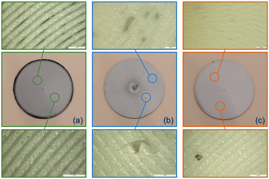
Figure 2.
Images of PETG specimens coated with IGUS manufactured with FFF: (a) with 0.3 mm coating thickness; (b) with 0.6 mm coating thickness; (c) with 0.9 mm coating thickness.
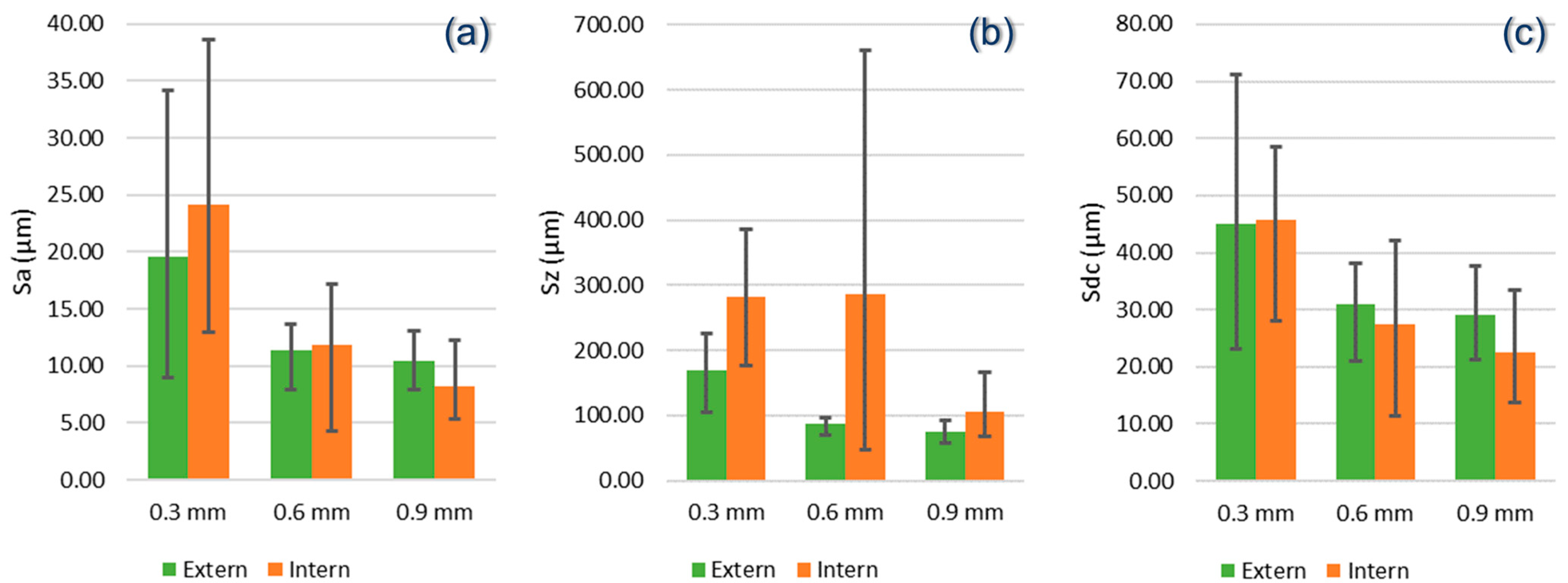
These defects will impact the surface quality and texture of the parts. If Sa is analysed (Figure 3a), understood as the average height deviations of the surface from a mean line within the measurement area, it is observed that as the coating thickness increases, there is a trend towards decreasing roughness. In fact, it is observed that when the coating is thinner, the deviations are very large, indicating that the average surface is very rough. However, there seems to be no significant difference between an internal and external area, which may mean that the surface is homogeneous.
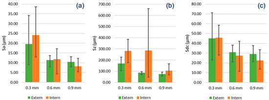
Figure 3.
Evolution of surface quality in terms of (a) Sa, (b) Sz, and (c) Sdc.
Analysing Sz (Figure 3b), understood as the maximum amplitude of the surface, it is observed that there are also higher values with the thinner coating thickness, although the difference is not as significant. However, there is a greater difference between the internal and external areas. This may indicate that the temperature accumulation in the central area due to the infill geometry generates more significant peaks, but as the coating thickness increases, this stabilises, probably due to the higher melting temperature of the coating.
Sdc, being a parameter more similar to Sa, behaves similarly (Figure 3c). In this case, Sdc provides a measure of how many peaks of a surface exceed a given height threshold per unit area. Thus, the thinner coating also behaves similarly as it does not have a high value of peaks but does have higher average values that homogenise as the thickness increases.
This makes sense as the extrusion temperature significantly influences the surface quality of FFF printed parts. A higher extrusion temperature tends to improve interlayer adhesion, resulting in a smoother surface (lower Sa) and reducing peak height (lower Sz). This is because the molten material flows better and fills gaps between adjacent layers more effectively, reducing overall surface roughness [36,37]. In this case, where one material is deposited on another, the interface is a problematic area, also due to the material change; therefore, increasing the number of layers of the new material improves quality.
However, different materials react differently to temperature changes, and it should not be forgotten that a hotter material is overlaid on the substrate’s melting temperature. However, it has been observed in reinforced materials that an increase in extrusion temperature also reduces surface roughness due to the better fusion and adhesion of the composite material [38]. In this case, this interface may be favoured by the higher extrusion temperature of the coating. Therefore, it is inferred that if the temperature of the second material were lower than the first, the result would be worse.
Additionally, analysis of variance (ANOVA) was performed for three surface quality metrics—average Sa (µm), average Sz (µm), and average Sdc (µm)—to analyse the significance of the antifriction coating thickness to the surface quality of FFF-fabricated specimens (Table 3). The ANOVA results provide information on whether the coating thickness has a significant effect on these metrics. For average Sa (µm), the F-value obtained was 4.197, with a p-value of 0.0797. Although the F-value is relatively high, the p-value exceeds the 0.05 threshold, indicating no statistical significance at the 5% level. This suggests that although there is a trend where the coating thickness might be influencing the average roughness, this influence is not conclusive with the available data. In the case of the average Sz (µm), the F-value was 2.774, with a p-value of 0.1398. This result shows a lower F-value and a p-value greater than 0.05, indicating no clear statistical significance in the effect of coating thickness on the maximum surface height. This implies that variability in average Sz is not significantly influenced by coating thickness under the conditions of this study. For average Sdc (µm), the F-value was 4.355, with a p-value of 0.0753. Similar to the average Sa case, although the F-value is notable, the p-value remains greater than 0.05, indicating that the relationship between coating thickness and the surface cut depth is not statistically significant. Additionally, there is no significance in the interaction of both factors. However, the observed trend could indicate an influence that might be more evident with a larger sample size or more detailed studies. Although the results do not show statistical significance in this analysis, the observed trends are consistent with Gupta and Sharma [39], who analysed the possibility of using antifriction coatings and observed that a thicker coating could improve surface quality. Similarly, Wang et al. [40] also found positive effects of surface modification on the tribological behaviour of FFF components, although this was a preliminary study. Similarly, it should be noted that in all three cases, there is a moderate negative correlation (Sa: −0.612; Sz: −0.533; Sdc: −0.619), suggesting that as coating thickness increases, quality tends to improve. This trend is consistent with the expectation that a thicker antifriction coating improves surface quality by reducing roughness.
Table 3.
ANOVA results of surface quality metrics vs. coating thickness.
It is important to note that traditionally, the roughness of a part is analyzed perpendicular to the manufacturing marks, which, in the case of FFF, would be perpendicular to the layer deposition. However, in this case, since the pin will slide over the outer face of the sample, the upper face of the samples is being analyzed, the roughness of which is conditioned by the deposition path, which is the same for all samples. Therefore, it makes sense that the coating thickness does not influence the roughness significantly because, even though increasing the thickness removes certain defects, these are smaller than the inherent marks from the material deposition.
Therefore, it should be clear that this behaviour will be important when studying the tribological behaviour of parts, as generally, a rougher surface tends to have a higher coefficient of friction. This is because irregularities and roughness on the surface increase the resistance to sliding between two surfaces in contact. In the context of parts manufactured by FFF, higher surface roughness can increase the coefficient of friction due to greater interaction between the peaks and valleys of the contact surfaces [41,42,43].
However, it should not be forgotten that in this case, there is another determining factor, which is load variation. The load also affects the coefficient of friction of surfaces. Generally, as the applied load increases, the coefficient of friction can vary due to the deformation and mechanical behaviour of the material under pressure [44,45]. This also occurs in the case of FFF, where it is observed that the coefficient of friction increases with the normal load applied [46,47].
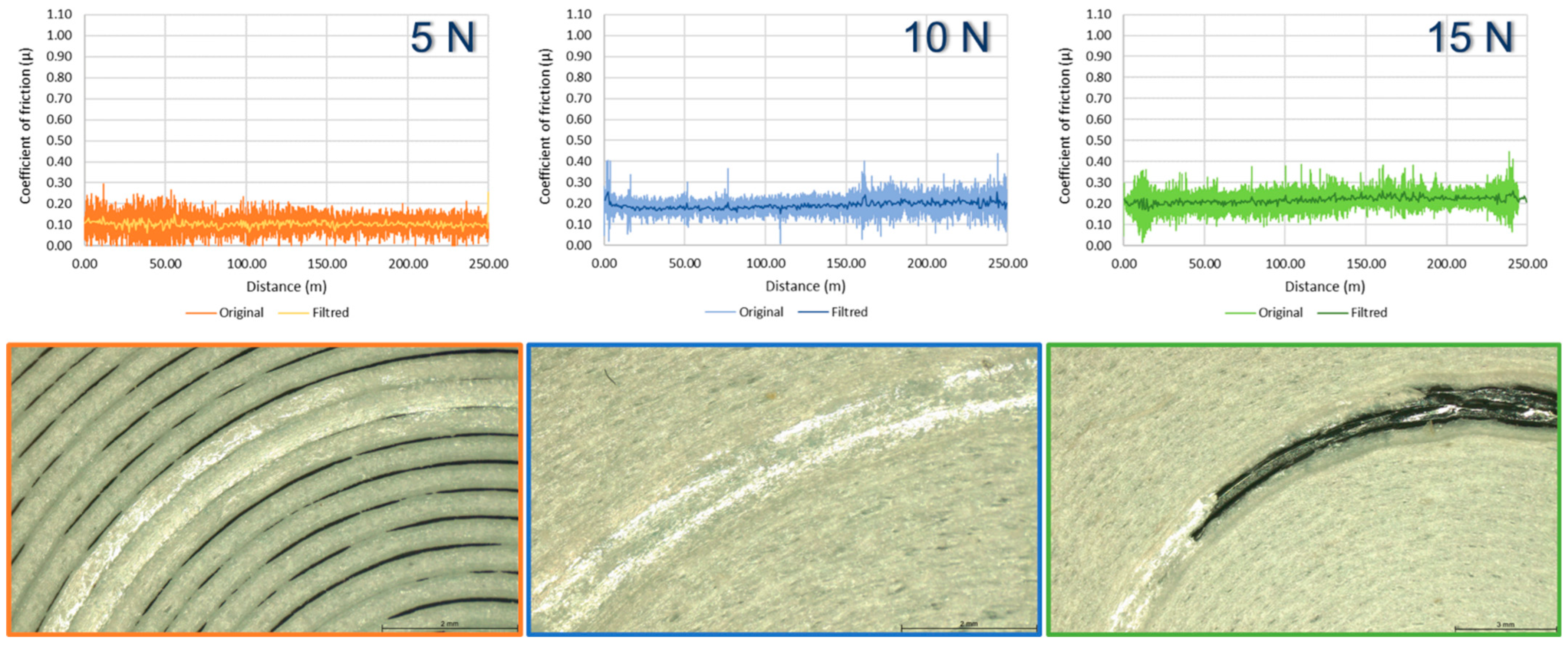
Analysing the tests conducted on specimens coated with a tribomaterial layer (0.3 mm), it is observed that as the load increases, the average coefficient of friction seems to increase (Figure 4). However, there is a much greater difference between 5 and 10 N than beyond. Similarly, it is observed that at the maximum load, this coating layer is worn away, implying that the part could not continue to function properly. On the other hand, in all three cases, the behaviour is very stable, with no significant jumps in the amplitude of the curve.
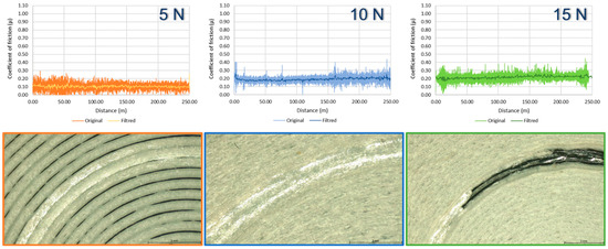
Figure 4.
Evolution of tests conducted on specimens coated with 0.3 mm coating.
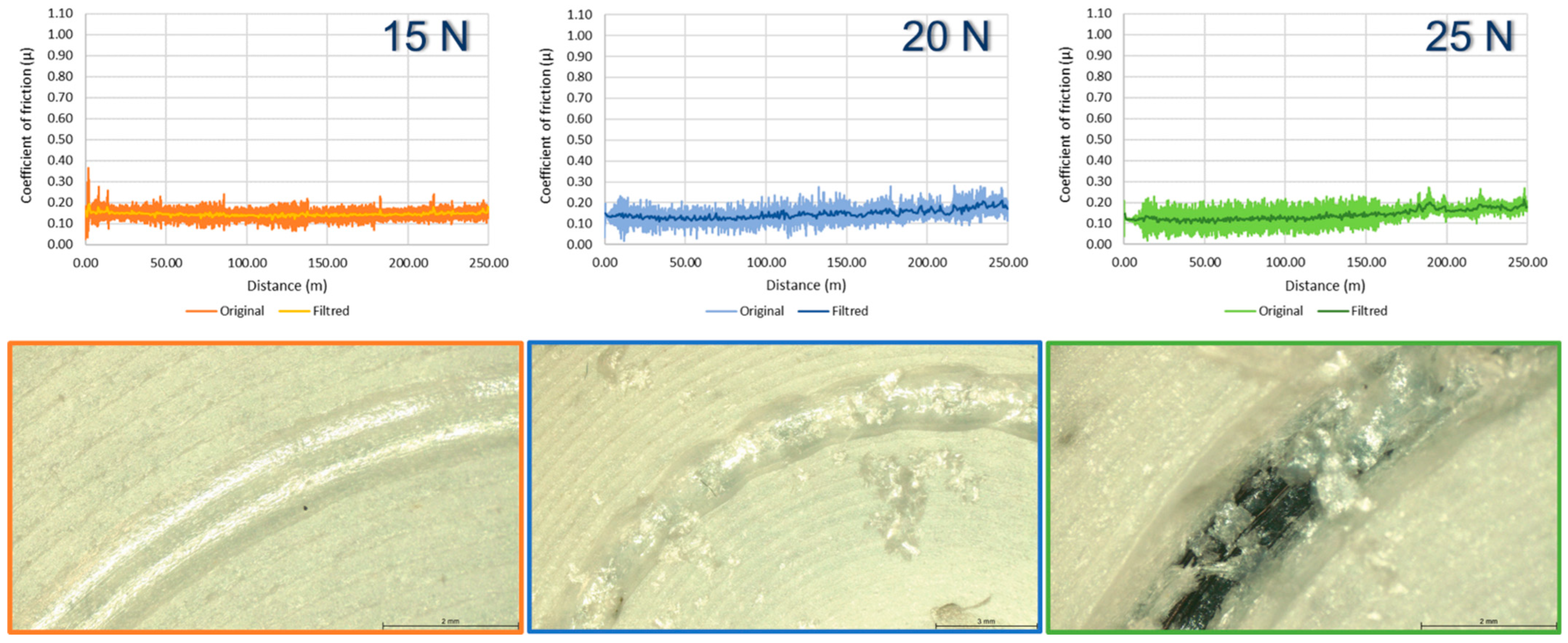
Increasing the coating and material load shows a similar but less-pronounced behaviour (Figure 5). The lower load in the case of 15 N seems to show the best coefficient of friction, increasing with the load until the coating breaks, which, in this case, is 0.6 mm. At 20 N, there are jumps in the width and depth of the groove that can be related to the stick and slip phenomenon. This phenomenon occurs when two surfaces in contact alternate between sticking phases (where they adhere and do not move) and sliding phases (where they slide over each other) and is closely related to the variation in the coefficient of friction under different loads, especially on FFF-fabricated surfaces [46]. On FFF-fabricated surfaces, variability in layer structure and surface roughness can make the stick and slip behaviour more pronounced. The applied load directly influences the transition between sticking and sliding phases, affecting the stability and smoothness of relative movement between the surfaces [48]. It can be observed that in the specimen tested at 25 N, from around 150 m, the curve behaviour changes, probably caused by slipping and coating loss.
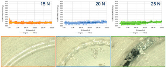
Figure 5.
Evolution of tests conducted on specimens coated with 0.6 mm coating.
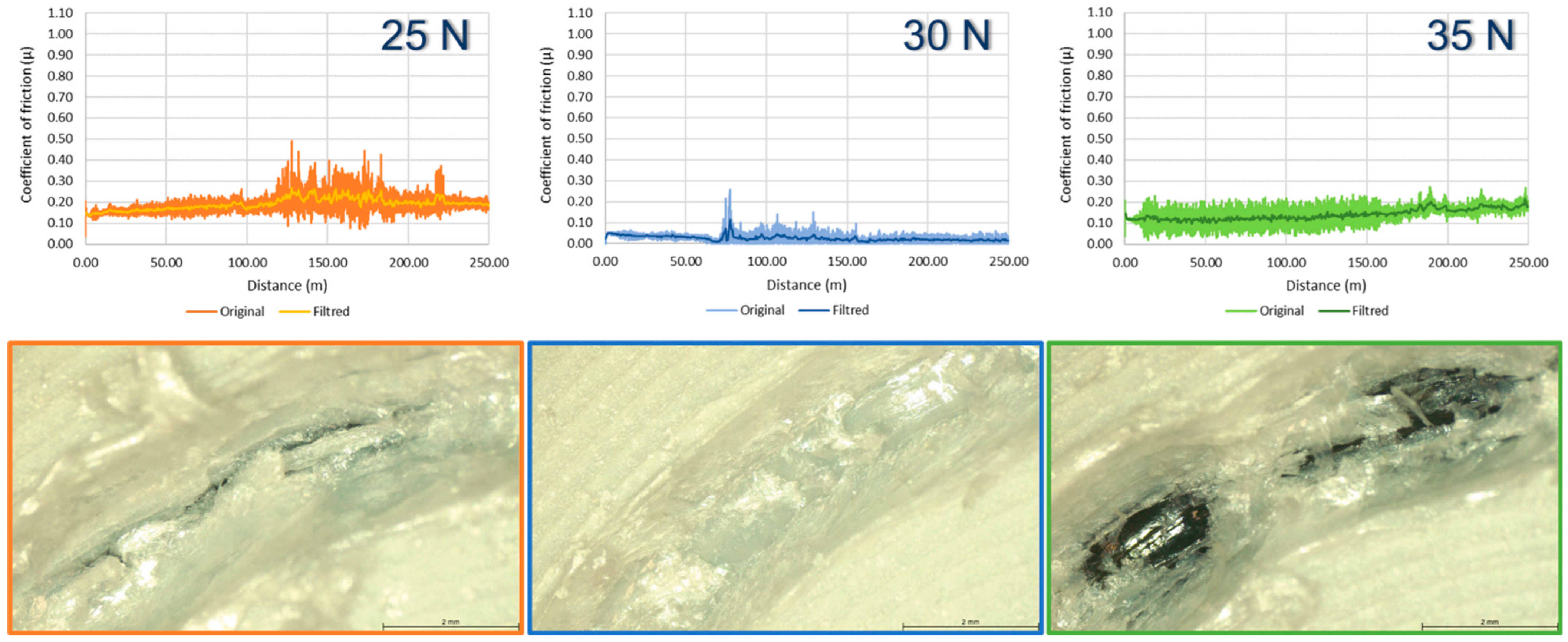
This phenomenon is even more pronounced in the case of thicker coatings, probably due to increased load (Figure 6). Increasing the coating thickness does not eliminate it at 25 N, although there are areas where the substrate of the specimen is visible, and a different behaviour appears from 125 m, which may indicate interference with the substrate. At 35 N, the coating breaks again, at a point similar to the previous specimen. In all cases, a morphology consistent with the stick–slip phenomenon is observed.
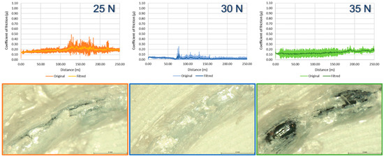
Figure 6.
Evolution of tests conducted on specimens coated with 0.9 mm coating.
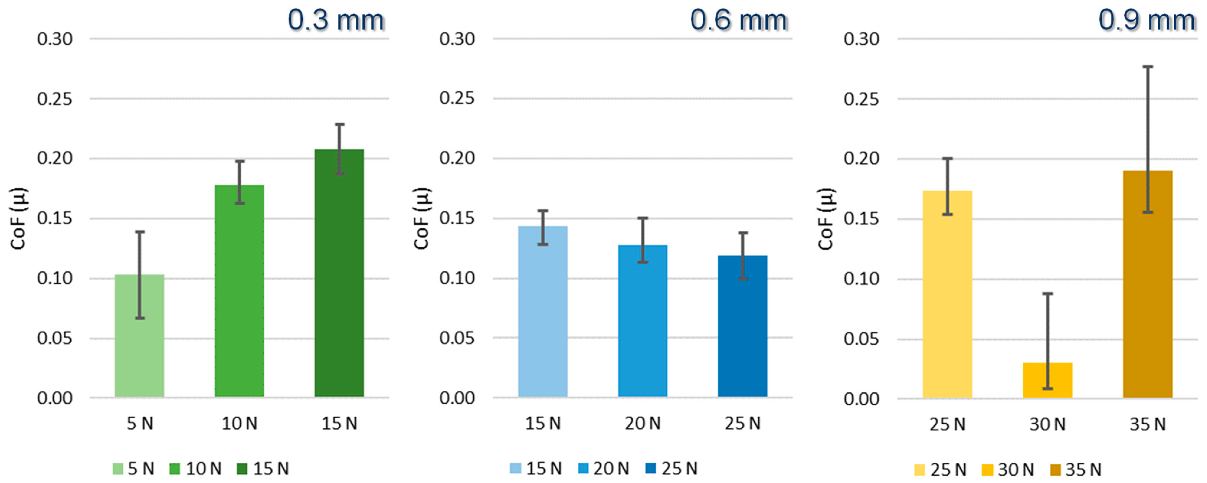
Analysing the average behaviour of the data (Figure 7), disparate behaviours are observed. In the thinnest coating, it is observed that the coefficient of friction increases with the load, completely wearing away the coating in certain areas at higher loads.

Figure 7.
Evolution of the average coefficient of friction.
On the other hand, increasing the coating shows more-stable behaviour, even manifesting a slight trend of decreasing the coefficient of friction, which is very unusual when compared to previous observations [46]. However, comparing it with the previously analysed graphs, the difference is insignificant compared to the amplitude of the tests (Figure 4), which are also quite stable.
However, comparing it with the thinner coating, it is observed that the coefficient of friction is significantly lower, which is consistent with previous observations, as depositing more material attenuates defects and levels the surfaces, positively impacting the coefficient of friction. Also, it is observed that increasing the coating thickness increases the coefficient of friction. This could be related to the previously mentioned stick–slip phenomenon and the formation of debris. Accumulating more material generates more detached particles that can hinder the pin’s movement, resulting in higher outcomes. In thinner coating layers, these particles are not generated, resulting in more stable behaviour.
This is noticeable in Figure 5, where the formation of burrs generating these particles is observed, except in the intermediate case of 30 N, which offers the best result. Therefore, the formation of particles caused by filament breakage and burr formation seems to have an opposite and negative behaviour. Additionally, these particles (Figure 8) have a morphology different from those observed in other FFF materials [10,11]. In this case, they form elongated and almost-curled particles, more similar to chips, which may indicate greater plastic deformation of the material.
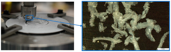
Figure 8.
Particles detached during the tribological tests.
Performing the statistical analysis of the data (Table 4), it is observed that for the average coefficient of friction case, the ANOVA results against the effect of coating thickness are F = 0.811 and p-value = 0.4024, indicating that the F-value is low and the p-value is greater than 0.05, suggesting that the coating thickness does not have a statistically significant effect on the average coefficient of friction. This suggests that variability in the coefficient of friction is not significantly influenced by coating thickness under the conditions of this study. A similar result is found with the effect of load, with F = 0.459 and p-value = 0.5233, indicating that the applied load also does not have a statistically significant effect on the average coefficient of friction. The amplitude of the friction curves also does not show significance with the coating layer thickness (F = 0.584; p-value = 0.4737), although the highest significance would be with the effect of load (F = 4.256; p-value = 0.0847), where, although it exceeds the 5% level, it is the closest, indicating greater dependence. Additionally, there is no significance in the interaction of both factors. Previous studies have already reported that despite the performance improvement that can be achieved with the use of coatings, conditions can vary the performance; therefore, they do not show clear significance [40,41].
Table 4.
ANOVA results of coating thickness and coefficient of friction.
The low significance of the friction coefficient with the coating thickness makes sense because although increasing the coating thickness may prolong the contact area over time, as long as this coating does not wear out, the tribological pair remains the same in all cases. Therefore, the friction coefficient should be similar since the same materials are in contact.
The correlation in this case is somewhat clearer as it shows that regarding the coefficient of friction, the correlation is weakly negative with both coating thickness (−0.251) and load (−0.109), but the amplitude shows a moderate negative correlation with coating thickness (−0.602) and an even greater correlation with load (−0.769). These results indicate that coating thickness and applied load have different levels of influence on the average coefficient of friction and the coefficient of friction amplitude. The moderate negative correlation between coating thickness and coefficient of friction amplitude is consistent with previous studies showing that antifriction coatings can improve tribological behaviour by reducing friction variability. The strong negative correlation between applied load and coefficient of friction amplitude also suggests that a higher load can stabilise tribological behaviour, which has been reported in the literature [39,40].
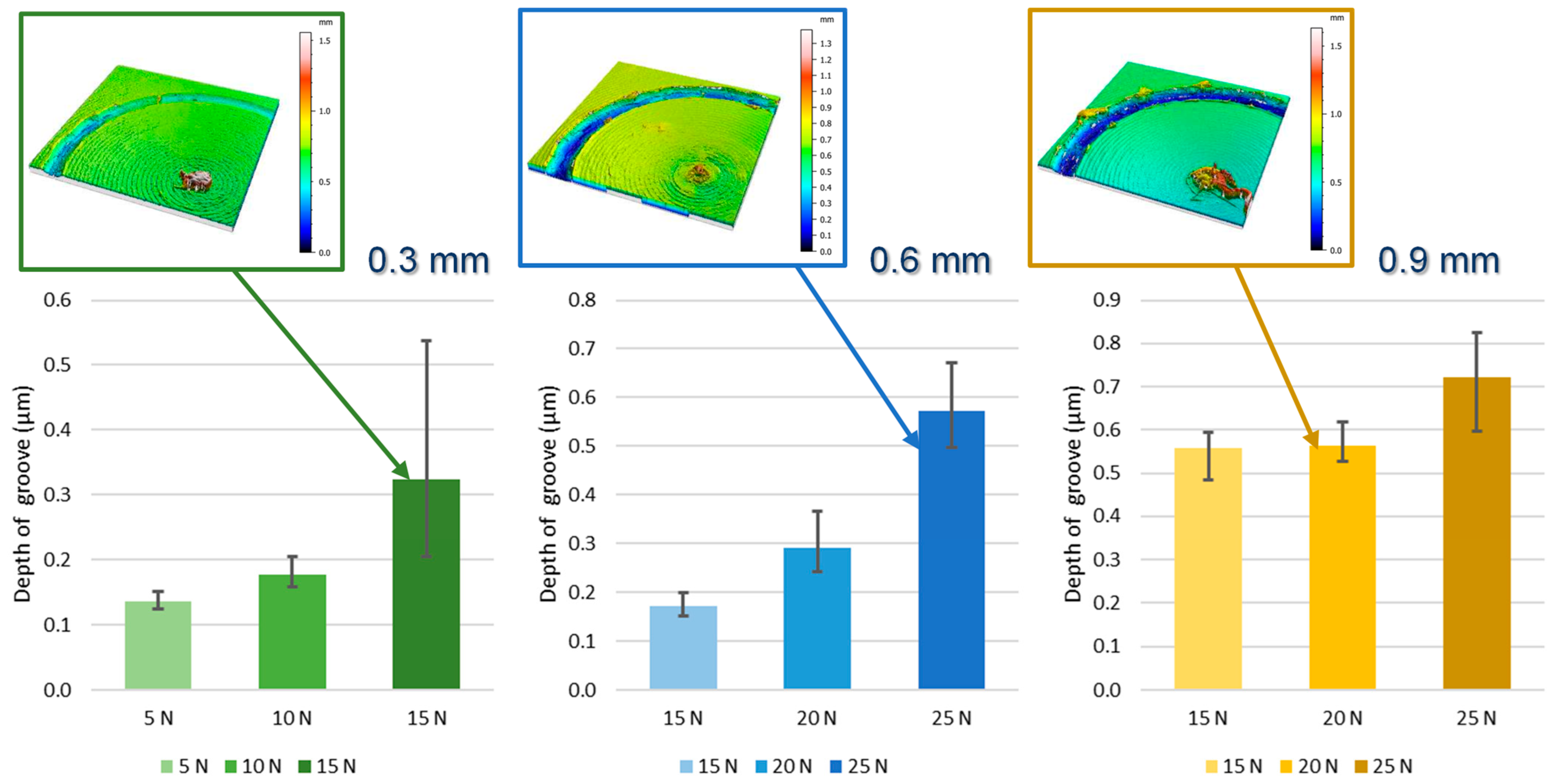
Analysing the generated groove, more linear behaviours appear. Analysing the groove width (Figure 9), it is observed that increasing the load increases the width in all cases, and at equal load, increasing the coating thickness results in less material loss. This aligns with the previously hypothesised trends. Regarding groove depth (Figure 10), the behaviour is similar, indicating that the wear behaviour of the parts is very homogeneous and stable. In this case, the statistical analysis (Table 5) reveals that coating thickness has little significance with respect to the groove width (F = 0.147; p-value = 0.7145) and groove depth (F = 0.488; p-value = 0.5110). In both cases, the F-value is very low, and the p-value is much greater than 0.05, indicating that variability in groove width and depth is not significantly influenced by coating thickness under the conditions of this study. This does not occur with load, which has significance with respect to groove width (F = 13.704; p-value = 0.0101) and groove depth (F = 15.495; p-value = 0.0077). In this case, the F-value is high, and the p-value is less than 0.05, indicating that he applied load has a statistically significant effect on groove depth and width. Although there is no significance in the interaction of both factors. These results indicate that the applied load has a significant influence on both groove width and depth, while coating thickness does not show a significant influence on these metrics.
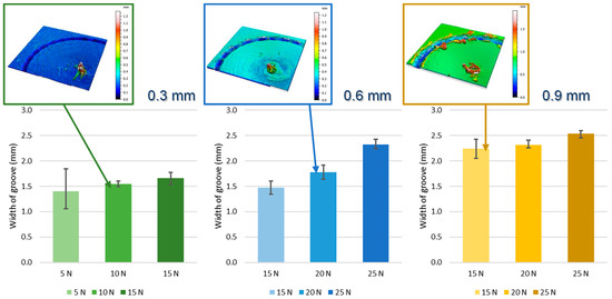
Figure 9.
Evolution of the wear groove width.

Figure 10.
Evolution of the wear groove depth.
Table 5.
ANOVA results of coating thickness and load.
However, as observed in the graphs, there is a correlation between groove width and coating thickness (0.828) and load (0.950) and between groove depth and coating thickness (0.806) and load (0.946), with all cases showing strong positive relationships, especially with load, verifying the previously observed trends. These results indicate that both coating thickness and applied load have a significant influence on groove width and depth. The strong positive correlation with load is consistent with previous studies showing that applied load during tribological tests has a notable impact on groove dimensions due to direct mechanical interactions between contact surfaces. The positive correlation with coating thickness also suggests that a thicker coating can influence wear characteristics, possibly due to greater material accumulation on the surface. However, the SEM observations should be performed on the groove, which could demonstrate more information. As a sample with a coating, the bond strength and coating structure play an important role in the wear behaviour [49].
This is consistent with the existing literature, where it has been observed that applied load during tribological tests significantly impacts the generated groove dimensions due to direct mechanical interaction between contact surfaces. Studies like that of Bian et al. [50] have reported that applied load can significantly affect the tribological behaviour and wear characteristics in FFF components. Similarly, Kim et al. [51] found that applied load influences tribological properties, supporting the idea that load is a critical factor in forming and characterising the wear groove.
4. Conclusions
This study investigated the tribological behaviour of parts manufactured by FFF using PETG coated with IGUS tribological filaments, evaluating the influence of coating thickness and applied load on wear and coefficient of friction.
- Effect of coating thickness: It was observed that increasing the IGUS coating thickness on PETG parts significantly reduces surface roughness. This translates into improved surface quality of the parts, which is critical for applications requiring low coefficient of friction stability and high wear resistance. However, coating thickness did not show a statistically significant influence on the average coefficient of friction, although a trend towards improvement with thicker coatings was observed.
- Impact of applied load: The applied load during tribological tests had a significant impact on groove depth and width. Higher loads increased both groove depth and width, indicating greater mechanical interaction between contact surfaces. This result underscores the importance of considering load in practical applications to avoid premature wear of parts.
- Stability of the coating: The study also revealed that with thicker coatings, the coefficient of friction stability was more consistent, although the stick–slip phenomenon manifested under high loads. This behaviour suggests that to optimise wear resistance and tribological stability, a proper balance between coating thickness and operating load is necessary.
- Importance of methodology: The methodology employed, based on pin-on-disc tests, proved effective in evaluating the tribological properties of multi-material parts manufactured with FFF. The results provide a solid foundation for future research and industrial applications, highlighting the relevance of using tribological coatings to improve the performance of 3D-printed parts.
In summary, this research significantly contributes to the knowledge of optimising the tribological properties of FFF-manufactured parts, offering practical guidance to improve the durability and efficiency of components in various industrial applications. This study does not seek to optimise the manufacture of the parts; this would be very interesting for a future study. Fixed parameters have been used but it is possible to determine which coating thickness is necessary for a given load.
Author Contributions
Conceptualisation, J.M.V.-M. and M.B.; experimental methodology, J.M.V.-M., D.T. and M.B.; formal analysis, J.M.V.-M. and I.D.S.; investigation J.M.V.-M., D.T., I.D.S. and M.B.; writing—original draft preparation, M.B. and D.T.; writing—review and editing, J.M.V.-M., I.D.S. and M.B.; project administration, I.D.S. All authors have read and agreed to the published version of the manuscript.
Funding
This research received no external funding.
Institutional Review Board Statement
Not applicable.
Informed Consent Statement
Not applicable.
Data Availability Statement
The original contributions presented in the study are included in the article. Further inquiries can be directed to the corresponding authors.
Acknowledgments
This work has been developed under the support of the Mechanical Engineering and Industrial Design department and the Vice-Rector’s Office for Scientific Policy of the University of Cadiz. The authors want to acknowledge the support from Spanish Government (SCIENCE AND INNOVATION MINISTRY/FEDER, Grant Project EQC2018-005131-P) from the 2018 State Program for Research Infrastructures and Scientific/Technical Equipment. The authors want to record their special thanks to the research group TEP-027 “Engineering and Technology of Materials and Manufacturing” of the University of Cadiz.
Conflicts of Interest
The authors declare no conflicts of interest.
References
- Attaran, M. The rise of 3-D printing: The advantages of additive manufacturing over traditional manufacturing. Bus. Horiz. 2017, 60, 667–688. [Google Scholar] [CrossRef]
- ISO/ASTM 52900:2021; Additive Manufacturing—General Principles—Fundamentals and Vocabulary. ISO International: Geneva, Switzerland, 2021.
- Zhakeyev, A.; Wang, P.; Zhang, L.; Shu, W.; Wang, H.; Xuan, J. Additive Manufacturing: Unlocking the Evolution of Energy Materials. Adv. Sci. 2017, 4, 10. [Google Scholar] [CrossRef]
- Reddy, M.; Hemasunder, B.; Chavan, P.; Dish, N.; Savio, A. Study on the significance of process parameters in improvising the tensile strength of FDM printed carbon fibre reinforced PLA. Mater. Today Proc. 2023; in press. [Google Scholar] [CrossRef]
- Liu, Z.; Lei, Q.; Xing, S. Mechanical characteristics of wood, ceramic, metal and carbon fiber-based PLA composites fabricated by FDM. J. Mater. Res. Technol. 2019, 8, 3741–3751. [Google Scholar] [CrossRef]
- Samykano, M.; Selvamani, S.K.; Kadirgama, K.; Ngui, W.K.; Kanagaraj, G.; Sudhakar, K. Mechanical property of FDM printed ABS: Influence of printing parameters. Int. J. Adv. Manuf. Technol. 2019, 102, 2779–2796. [Google Scholar] [CrossRef]
- Mohamed, O.; Masood, S.; Bhowmik, J. Experimental Investigations of Process Parameters Influence on Rheological Behaviour and Dynamic Mechanical Properties of FDM Manufactured Parts. Mater. Manuf. Process. 2016, 31, 1983–1994. [Google Scholar] [CrossRef]
- Chalgham, A.; Ehrmann, A.; Wickenkamp, I. Mechanical Properties of FDM Printed PLA Parts before and after Thermal Treatment. Polymers 2021, 13, 1239. [Google Scholar] [CrossRef]
- Gamboa, C.B.; Martín-Béjar, S.; Trujillo Vilches, F.J.; Herrera Fernández, M.; Sevilla Hurtado, L. Fatigue Behaviour Analysis in Reinforced PLA Parts Manufactured by FDM. Key Eng. Mater. 2023, 956, 91–98. [Google Scholar] [CrossRef]
- Batista, M.; Blanco, D.; del Sol, I.; Piñero, D.; Vazquez, J.M. Tribological characterization of Fused Deposition Modelling parts. IOP Conf. Ser. Mater. Sci. Eng. 2021, 1193, 012068. [Google Scholar] [CrossRef]
- Batista, M.; del Sol, I.; Salguero, J.; Piñero, D. Product Design: Study of the Tribological Properties of FDM PETG Products. In Advances in Design Engineering III, INGEGRAF 2022. Lecture Notes in Mechanical Engineering; Springer: Cham, Switzerland, 2023; pp. 431–443. [Google Scholar]
- Amiruddin, H.; Abdollah, M.; Norashid, N.A.N. Comparative study of the tribological behaviour of 3D-printed and moulded ABS under lubricated condition. Mater. Res. Express 2019, 6, 085328. [Google Scholar] [CrossRef]
- Srinivasan, R.; Babu, B.; Rani, V.U.; Suganthi, M.; Dheenasagar, R. Comparision of tribological behaviour for parts fabricated through fused deposition modelling (FDM) process on abs and 20% carbon fibre PLA. Mater. Today Proc. 2020, 27, 1780–1786. [Google Scholar] [CrossRef]
- Mohamed, O.; Masood, S.; Bhowmik, J.; Somers, A. Investigation on the tribological behaviour and wear mechanism of parts processed by fused deposition additive manufacturing process. J. Manuf. Process. 2017, 29, 149–159. [Google Scholar] [CrossRef]
- Panneerselvam, K.; Ramesh, M. Mechanical investigation and optimization of parameter selection for Nylon material processed by FDM. Mater. Today Proc. 2021, 46, 9303–9307. [Google Scholar] [CrossRef]
- Durga Rajesh, K.; Ganesh, N.; Yaswanth, S.; Reddy, K.; Mishra, H.; Tekkali, K. Experimental research on the mechanical characteristics of fused deposition modelled ABS, PLA and PETG specimens printed in 3D. Mater. Today Proc. 2023; in press. [Google Scholar] [CrossRef]
- Hanon, M.M.; Alshammas, Y.; Zsidai, L. Effect of print orientation and bronze existence on tribological and mechanical properties of 3D-printed bronze/PLA composite. Int. J. Adv. Manuf. Technol. 2020, 108, 553–570. [Google Scholar] [CrossRef]
- Kumar, R.; Sharma, H.; Saran, C.; Tripathy, T.S.; Sangwan, K.S.; Herrmann, C. A Comparative Study on the Life Cycle Assessment of a 3D Printed Product with PLA, ABS & PETG Materials. Procedia CIRP 2022, 107, 15–20. [Google Scholar] [CrossRef]
- Khan, I.; Muhammad, T.; Muhammad, A.; Muhammad, S.; Hira, F.; Muammer, K. Parametric investigation and optimisation of mechanical properties of thick tri-material based composite of PLA-PETG-ABS 3D-printed using fused filament fabrication. Compos. Part C Open Access 2023, 12, 100392. [Google Scholar] [CrossRef]
- Lakshman, S.; Karthick, A.; Dinesh, C. Evaluation of mechanical properties of 3D printed PETG and Polyamide (6) polymers. Chem. Phys. Impact 2024, 8, 100491. [Google Scholar] [CrossRef]
- Fallah, A.; Saleem, Q.; Koc, B. Assessment of mechanical properties and shape memory behaviour of 4D printed continuous fiber-reinforced PETG composites. Compos. Part A Appl. Sci. Manuf. 2024, 181, 108165. [Google Scholar] [CrossRef]
- IGUS. Available online: https://www.igus.es/ (accessed on 20 July 2024).
- Gómez López, V. Diseño, Prototipado y Validación Funcional de una CNC de Porex de 4 Ejes. Terrassa, Barcelona, Escola Tecnica Superior de Enginyeries Industrial i Aeronautica de Terrassa. 2019. Available online: http://hdl.handle.net/2117/172351 (accessed on 20 July 2024).
- Dwyer, G.; Chadebecq, F.; Amo, M.T.; Bergeles, C.; Maneas, E.; Pawar, V.; Poorten, E.V.; Deprest, J.; Ourselin, S.; De Coppi, P.; et al. A Continuum Robot and Control Interface for Surgical Assist in Fetoscopic Interventions. IEEE Robot. Autom. Lett. 2017, 2, 1656–1663. [Google Scholar] [CrossRef]
- Singh, R.; Kumar, S.; Kumar, R. Chapter 6-On dual/multimaterial composite matrix for smart structures: A case study of ABS-PLA, HIPS-PLA-ABS. In Additive Manufacturing Materials and Technologies; Singh, R., Ed.; Elsevier: Amsterdam, The Netherlands, 2022; pp. 89–101. [Google Scholar] [CrossRef]
- Li, J.; Jiao, Y.; Xu, C.; Zhang, L.; Li, Q.; Ren, L. Study on the multi-environmental wear resistance of a shell-imitating multilayer multimaterial composite carbon fiber. Tribol. Int. 2024, 198, 109930. [Google Scholar] [CrossRef]
- Mehrpouya, M.; Ghalayaniesfahani, A.; Postmes, J.; Gibson, I. Tailoring mechanical properties in 3D printed multimaterial architected structures. J. Mech. Behav. Biomed. Mater. 2024, 152, 106431. [Google Scholar] [CrossRef] [PubMed]
- Singh, R.; Patel, B.A. The Effects of Material Extrusion Printing Speed on the Electrochemical Activity of Carbon Black/Polylactic Acid Electrodes. Anal. Chem. 2022, 9, e202200831. [Google Scholar] [CrossRef]
- Hanon, M.; Kovács, M.; Zsidai, L. Tribology behaviour investigation of 3D printed polymers. Int. Rev. Appl. Sci. Eng. 2019, 10, 173–181. [Google Scholar] [CrossRef]
- ASTM G99-17; Standard Test Method for Wear Testing with a Pin-on-Disk Apparatus. ASTM International: Washington, DC, USA, 2017.
- ISO 25178-2:2012(en); Geometrical Product Specifications (GPS)—Surface Texture: Areal—Part 2: Terms, Definitions and Surface Texture Parameters. ISO International: Geneva, Switzerland, 2012.
- EUR 15178N; The Development of Methods for the Characterisation of Roughness in Three Dimensions, Stout, Sullivan, Dong, Mainsah, Luo, Mathia, Zahouani. Commission of the European Communities: Brussels, Belgium, 1993.
- Zheng, X.; Liu, J.; Du, S.; Zhang, Y. Test and analysis of the tribofilm and surface state during rolling contact under lubrication condition. Tribol. Int. 2023, 187, 108774. [Google Scholar] [CrossRef]
- Fu, X.; Zhang, X.; Huang, Z. Axial crushing of Nylon and Al/Nylon hybrid tubes by FDM 3D printing. Compos. Struct. 2021, 256, 113055. [Google Scholar] [CrossRef]
- Akhoundi, B.; Nabipour, M.; Kordi, O.; Hajami, F. Calculating printing speed in order to correctly print PLA/ continuous glass fiber composites via fused filament fabrication 3D printer. J. Thermoplast. Compos. Mater. 2023, 36, 162–181. [Google Scholar] [CrossRef]
- Yang, L.; Li, S.; Li, Y.; Yang, M.; Yuan, Q. Experimental Investigations for Optimizing the Extrusion Parameters on FDM PLA Printed Parts. J. Mater. Eng. Perform. 2019, 28, 169–182. [Google Scholar] [CrossRef]
- Kumar, S.; Vyavahare, S.; Kootikuppala, J. Experimental Study of Effect of Process Parameters on Surface Roughness and Dimensional Accuracy of Parts Fabricated by Fused Deposition Modelling. In Recent Advances in Manufacturing Modelling and Optimization; Kumar, S., Ramkumar, J., Kyratsis, P., Eds.; Lecture Notes in Mechanical Engineering; Springer: Singapore, 2022. [Google Scholar] [CrossRef]
- Abas, M.; Awadh, M.A.; Habib, T.; Noor, S. Analyzing Surface Roughness Variations in Material Extrusion Additive Manufacturing of Nylon Carbon Fiber Composites. Polymers 2023, 15, 3633. [Google Scholar] [CrossRef] [PubMed]
- Gupta, R.K.; Sharma, P. Influence of Anti-Friction Coatings on Tribological Performance in FDM Fabricated Components. J. Tribol. 2020, 142, 051702. [Google Scholar] [CrossRef]
- Wang, L.; Li, Y.; Zhang, H. Effects of Surface Modification on the Tribological Behaviour of FDM Components. Surf. Coat. Technol. 2019, 370, 238–244. [Google Scholar] [CrossRef]
- Baier, T.; Schmid, M.; Wegener, K. Tribological behaviour of additively manufactured polymer composites. J. Tribol. 2019, 141, 082901. [Google Scholar] [CrossRef]
- Vyavahare, S.; Kumar, S.; Panghal, D. Experimental study of surface roughness, dimensional accuracy and time of fabrication of parts produced by fused deposition modelling. Rapid Prototyp. J. 2020, 26, 1535–1554. [Google Scholar] [CrossRef]
- Saad, M.S.; Nor, A.; Baharudin, M.E.; Zakaria, M.Z.; Aiman, A. Optimization of surface roughness in FDM 3D printer using response surface methodology, particle swarm optimization, and symbiotic organism search algorithms. Int. J. Adv. Manuf. Technol. 2019, 105, 5121–5137. [Google Scholar] [CrossRef]
- Maegawa, S.; Itoigawa, F.; Nakamura, T. Effect of normal load on coefficient of friction for sliding contact between rough rubber surface and rigid smooth plane. Tribol. Int. 2015, 92, 335–343. [Google Scholar] [CrossRef]
- Jiang, H.; Browning, R.; Fincher, J.; Gasbarro, A.; Jones, S.; Sue, H. Influence of surface roughness and contact load on coefficient of friction and scratch behaviour of thermoplastic olefins. Appl. Surf. Sci. 2008, 254, 4494–4499. [Google Scholar] [CrossRef]
- Mohamed, O.; Masood, S.; Bhowmik, J. A parametric investigation of the friction performance of PC-ABS parts processed by FDM additive manufacturing process. Polym. Adv. Technol. 2017, 28, 1911–1918. [Google Scholar] [CrossRef]
- Singh, R.; Singh, S. Investigating the coefficient of friction in functionally graded rapid prototyping of Al–Al2O3 composite prepared by fused deposition modelling. Assem. Autom. 2017, 37, 154–161. [Google Scholar] [CrossRef]
- Farimani, F.; Rooij, M.; Hekman, E.; Misra, S. Frictional characteristics of Fusion Deposition Modeling (FDM) manufactured surfaces. Rapid Prototyp. J. 2020, 26, 1095–1102. [Google Scholar] [CrossRef]
- Yang, C.; Cui, S.; Fu, R.K.Y.; Sheng, L.; Wen, M.; Xu, D.; Zhao, Y.; Zheng, Y.; Chu, P.K. Optimization of the in vitro biodegradability, cytocompatibility, and wear resistance of the AZ31B alloy by micro-arc oxidation coatings doped with zinc phosphate. J. Mater. Sci. Technol. 2024, 179, 224–239. [Google Scholar] [CrossRef]
- Bian, X.; Wei, D.; Wu, G.; Zhang, J.; Shao, F. Tribological behaviour of 3D printed polymers under dry sliding conditions. Wear 2018, 402–403, 66–75. [Google Scholar] [CrossRef]
- Kim, H.; Lee, D.; Park, S.; Kim, W. Influence of load and sliding speed on tribological behaviour of 3D printed polymers. Polym. Test. 2019, 75, 69–76. [Google Scholar] [CrossRef]


Disclaimer/Publisher’s Note: The statements, opinions and data contained in all publications are solely those of the individual author(s) and contributor(s) and not of MDPI and/or the editor(s). MDPI and/or the editor(s) disclaim responsibility for any injury to people or property resulting from any ideas, methods, instructions or products referred to in the content. |
© 2024 by the authors. Licensee MDPI, Basel, Switzerland. This article is an open access article distributed under the terms and conditions of the Creative Commons Attribution (CC BY) license (https://creativecommons.org/licenses/by/4.0/).