Article

Harmonic Suppression in Permanent Magnet Synchronous Motor Currents Based on Quasi-Proportional-Resonant Sliding Mode Control

School of Mechanical Engineering, Zhejiang Sci-Tech University, Hangzhou 310018, China
*
Author to whom correspondence should be addressed.
Appl. Sci. 2024, 14(16), 7206; https://doi.org/10.3390/app14167206
Submission received: 15 July 2024 / Revised: 10 August 2024 / Accepted: 13 August 2024 / Published: 16 August 2024

Abstract

:
The output voltage of inverters is influenced by nonlinear factors such as dead time and voltage drops, injecting low-order harmonics. This results in fifth and seventh harmonic distortions in the stator current, causing periodic torque ripples and significantly affecting the control precision of Permanent Magnet Synchronous Motors (PMSMs). To address this issue, this paper proposes a control strategy named quasi-proportional-resonant sliding mode control (QPR-SMC). Initially, sliding mode control is employed as the current controller to enhance disturbance rejection capability and provide a rapid dynamic response. Subsequently, a quasi-proportional-resonant controller is introduced to extract the sixth harmonic component from the current, which is then used as a compensation term for the sliding mode control surface. Finally, the current tracking error and the compensation term are combined as inputs to the sliding mode control law, forming a current error-proportional resonant-sliding mode control surface. This approach enhances the harmonic suppression capability of the system. The results demonstrate that the proposed method effectively reduces the fifth and seventh harmonic components in the three-phase current and mitigates motor jitter by suppressing the sixth harmonic in the d–q coordinate system.

1. Introduction

PMSMs are renowned for their high efficiency, rapid response, and low power losses, making them widely used in high-precision AC servo systems and electric vehicle drives [1]. However, distortions in the motor air gap magnetic field, along with non-ideal factors such as inverter dead-time effects and voltage drop across devices, introduce harmonic components into the stator current. These harmonic components, specifically the 5th, 7th, 11th, and 13th harmonics, contribute to periodic torque ripples [2]. Among these, the fifth and seventh harmonics are particularly detrimental to speed control systems. The interaction between the fifth and seventh harmonics in the stator current and the fundamental magnetic field of the rotor’s permanent magnets generates a sixth-order torque ripple. These ripples cause fluctuations in motor speed, thereby reducing the precision of servo control systems. Consequently, the primary focus of harmonic control in PMSMs is on mitigating the fifth and seventh harmonics.
Extensive research has been conducted both domestically and internationally on suppressing harmonic currents, improving motor current waveforms, and mitigating torque ripples [3]. These methods can be categorized into two main approaches. The first approach focuses on motor design, primarily optimizing the motor structure to enhance the sinusoidal distribution of the air-gap magnetic field [4]. However, this complicates the motor structure and increases manufacturing costs. The second approach emphasizes system control strategies, employing harmonic compensation algorithms to suppress current harmonics. This method has the advantages of not requiring additional hardware and being easily integrated into motor systems. Therefore, this paper focuses on the use of control algorithms to suppress current harmonics.
The advantages of Iterative Learning Control (ILC) lie in its high control precision and independence from the mathematical model of the control system, making it widely used in reducing current harmonics and torque fluctuations [5,6]. Existing research leverages ILC to optimize motor performance by dynamically adjusting control strategies to minimize harmonic errors and disturbances. In [7], the authors proposed a rotor position harmonic error suppression method based on adaptive ILC for sensorless PMSM drives that does not require offline detection and identification of harmonic frequencies and exhibits strong suppression capabilities for various harmonic error components. Furthermore, In [8], the authors introduced a torque ripple suppression method for PMSM based on SMA-optimized ILC, which does not rely on prior knowledge of system and motor parameters and reduces torque ripple by mitigating the effects of higher-order harmonics in the control current. However, its complex structure and significant computational burden pose considerable challenges for practical applications. Current harmonic suppression technology based on repetitive control methods offers high steady-state accuracy, minimal parameter adjustments, and simple control structures [9]. Various studies have focused on different aspects and improvements of repetitive control technology. In one group of studies, the structure and system integration of repetitive controllers were optimized. In [10], the authors constructed three closed-loop systems using a power amplifier and repetitive controller, achieving high-precision suppression of harmonic vibration forces. Another group of studies focuses on the algorithmic optimization of repetitive control. In [11], the authors explored a hybrid control method combining second-order odd harmonic repetitive control and finite-dimensional repetitive control, effectively addressing the non-integer delay problem in digital repetitive control. Additionally, in [12], the authors proposed an adaptive odd-order repetitive control method capable of suppressing odd harmonic currents in magnetic suspension bearings without the need for a speed sensor. However, repetitive control requires high accuracy of the center frequency, necessitating the integration of frequency adaptation algorithms in practical applications where the center frequency may vary. The current harmonic suppression algorithm, based on the Extended State Observer (ESO), treats current harmonics as disturbances and eliminates them through the state observer. Due to the low model precision requirements of ESO, the algorithm demonstrates strong robustness against parameter variations and external disturbances. In [13], the authors designed an Extended Harmonic State Observer (EHSO) to estimate and suppress multiple harmonic disturbances. In [14], the authors addressed three shortcomings of traditional ESO by proposing three enhanced ESOs to tackle the current harmonic issues in permanent magnet motors. However, improper gain settings in ESO can introduce stability problems, particularly oscillations under high gain settings.
Sliding Mode Control (SMC) has garnered significant attention from researchers in the field of harmonic suppression in motor drives due to its robustness against system parameter variations and external disturbances. However, traditional SMC strategies often face the challenge of chattering, which limits their practical applications. This issue has been addressed by integrating advanced control techniques and algorithms. In one set of studies, improved control strategies were employed to optimize the performance of SMC. For instance, the Speed-Adaptive Super-Twisting Control (S-AST) proposed in [15], which combines Proportional–Integral (PI) and Super-Twisting (ST) controllers, significantly reduces chattering and effectively lowers the total harmonic distortion (THD) in PMSMs. Additionally, the current harmonic and imbalance suppression strategy based on vector space decomposition control, as discussed in [16], successfully mitigates the fifth and seventh current harmonics and addresses imbalance issues. In another set of studies, advanced control technologies were used to enhance harmonic suppression. In [17], the authors employed a continuous fractional-order sliding mode control strategy based on the Output Feedback Feature Selection Neural Network (OFFSNN), significantly improving power quality and harmonic suppression in the grid. These advancements demonstrate the potential of integrating innovative control techniques to overcome traditional challenges in SMC, thereby broadening its application in motor drive systems.
Another strategy for harmonic suppression is the use of resonant controllers, which offer high computational efficiency and flexibility. Compared to ideal resonant controllers, quasi-proportional-resonant controllers increase the bandwidth of the resonant frequency, thereby enhancing system stability. Additionally, by integrating the benefits of proportional control, these controllers improve the response across the entire frequency range. As a result, quasi-proportional-resonant controllers effectively compensate for harmonic currents, reducing their content and achieving harmonic current suppression. This makes them a more suitable choice for complex and demanding practical applications [18]. Resonant controllers have been extensively studied for their excellent performance in precise harmonic suppression. In one line of research focused on optimizing resonant controllers, a Small Phase Angle Resonant Controller (SPARC) was proposed in [19]. This controller addresses the excessive phase angle issue at the resonant frequency found in traditional resonant controllers, significantly enhancing the suppression of current harmonics in PMSM. In another line of research, composite resonant control strategies that combine other control techniques have been explored. For instance, in [20], the authors proposed a low-order current harmonic suppression strategy based on a Butterworth filter and a quasi-proportional-resonant controller, optimizing current harmonic suppression in traction drive systems. Additionally, the Proportional-Integral-Resonant Adaptive Controller (PIRAC) introduced in [21] effectively addresses speed fluctuations caused by current measurement errors through segmented phase compensation, enhancing system stability and harmonic suppression performance across different speeds.
In summary, this study employs a quasi-proportional-resonant controller (QPRC). Typically, a control structure comprising several resonant controllers in parallel with a PI controller is used to regulate current and compensate for current harmonics [22]. However, traditional PI controllers are sensitive to parameter mismatches, which can reduce the tracking accuracy of the current loop. Therefore, robustness must be considered in the design of current controllers. This paper proposes a control strategy called Dynamic Harmonic Compensation Sliding Mode Control (DHC-SMC), which offers enhanced robustness and better harmonic disturbance suppression. When resonant controllers are combined with sliding mode controllers, the structure can provide extremely high gain at specific frequencies, effectively suppressing periodic disturbances or harmonics at precise frequencies. Additionally, the introduction of sliding mode controllers, which do not rely on an accurate system model and possess strong disturbance rejection capabilities, effectively complements the resonant controller in suppressing non-periodic harmonics.
The remainder of this paper is organized as follows: Section 1 describes the harmonic model of the PMSM and analyzes the torque ripple caused by current harmonics. Section 2 outlines the design process and performance analysis of the proposed control method. Section 3 validates the effectiveness of the proposed control strategy through experimental verification on a PMSM drive system. Finally, Section 4 provides a summary of this paper.

2. A Harmonic Model of PMSMs

During the steady-state operation of PMSM, factors such as air gap magnetic field distortion, inverter voltage drop, and the inherent magnetic field distortion of the motor can cause the current waveform to become distorted. These distorted current waveforms generate various harmonic components, with the fifth and seventh harmonics having a particularly significant impact on motor operation. These harmonics induce torque ripple at the sixth harmonic frequency, thereby compromising the stability of motor operation. To thoroughly investigate and address this issue, a corresponding mathematical model of the PMSM was established.
Assuming the PMSM is ideal under perfect conditions, the stator voltage equations and stator flux linkage equations in the d–q coordinate system can be derived as follows:
[ u d u q ] = [ R s w e L q w e L d R s ] [ i d i q ] + d dt [ i d i q ] + [ 0 w e Ψ f ]
where u d and u q are the voltage components of the stator in the d-axis and q-axis, respectively; i d and i q are the current components of the stator in the d-axis and q-axis, respectively; L d and L q are the inductances on the d-axis and q-axis, respectively; Ψ f is the permanent magnet flux linkage of the motor rotor; w e is the electrical angular speed of the motor; and Ψ d and Ψ q are the flux linkages in the d-axis and q-axis of the stator, respectively.
Considering a surface-mounted PMSM, the stator inductances in the d-axis and q-axis are equal, i.e., L d = L q = L s . In the d–q coordinate system, the electromagnetic torque equation can be expressed as follows:
T e = 3 2 p Ψ f i q
where T e represents the electromagnetic torque of the motor, and p denotes the number of pole pairs.
Under mechanical load, the dynamic motion equation of the PMSM can be expressed as follows:
T e T L B w = J d ω d t
where T L represents the load torque; J is the moment of inertia of the motor; w is the mechanical angular velocity; and B is the damping coefficient.
The expressions for the fifth and seventh harmonic components of the three-phase stator current are defined as follows:
{ i A 5 = I 5 sin ( 5 ω t + φ 5 ) i B 5 = I 5 sin ( 5 ω t + φ 5 + 120 ° ) i C 5 = I 5 sin ( 5 ω t + φ 5 120 ° )
{ i A 7 = I 7 sin ( 7 ω t + φ 7 ) i B 7 = I 7 sin ( 7 ω t + φ 7 120 ° ) i C 7 = I 7 sin ( 7 ω t + φ 7 + 120 ° )
After performing a rotor flux-oriented coordinate transformation, the expressions for the fifth and seventh current harmonic components in the two-phase rotating coordinate system (d–q coordinate system) are given by:
{ i d 5 = I 5 cos ( 6 ω t + φ 5 ) i q 5 = I 5 sin ( 6 ω t + φ 5 )
{ i d 7 = I 7 cos ( 6 ω t + φ 7 ) i q 7 = I 7 sin ( 6 ω t + φ 7 )
It can be observed that the frequencies of the fifth and seventh current harmonics in the d–q coordinate system are both six times the fundamental frequency. Additionally, the harmonic torque will induce a frequency component identical to the harmonic speed component, with the sixth harmonic torque being the primary component [21]. Therefore, reducing the sixth harmonic current in the d–q coordinate system is equivalent to reducing the fifth and seventh harmonics in the three-phase stator current.

3. The Dynamic Harmonic Compensation Sliding Mode Control Method

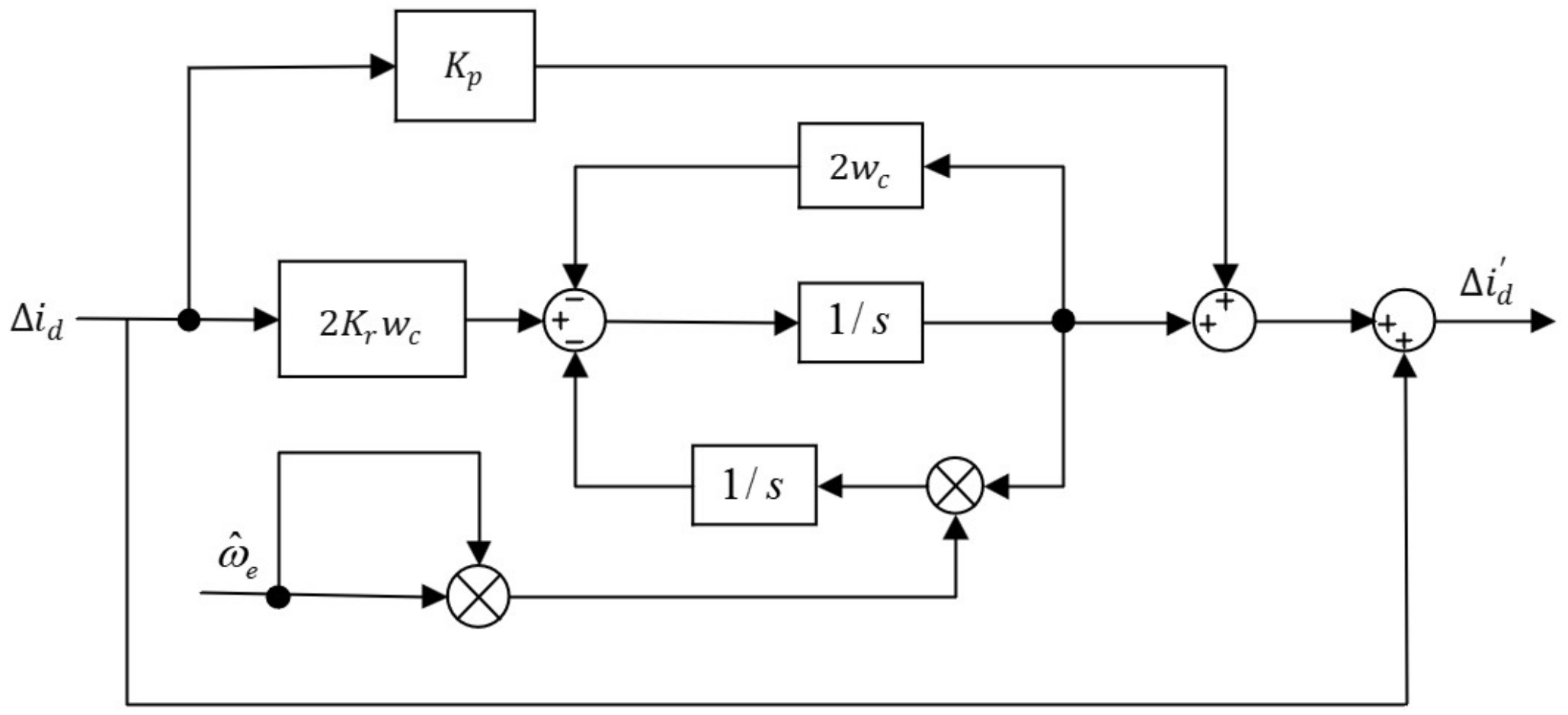
3.1. Proportional Resonant Controller

In current loop control, PI controllers are typically used to regulate current. However, due to the presence of harmonic currents, the current in the d–q coordinate system contains not only the fundamental component but also harmonic components. Since PI controllers cannot accurately track harmonic currents, the PI current control algorithm in the d–q coordinate system struggles to eliminate these harmonics. An ideal resonant controller provides infinite gain at its resonant frequency point, enabling it to track harmonic currents without steady-state error and effectively suppress the influence of harmonics in three-phase currents. The general expression of an ideal resonant controller is as follows:
G R = 2 K r s s 2 + ω 0 2
Due to the absence of a damping term in the ideal resonant controller, its bandwidth at the resonant frequency is very narrow, making the system extremely sensitive to frequency variations. By adjusting the cutoff frequency, the bandwidth of the controller can be expanded, which not only reduces the sensitivity of the system to frequency changes but also enhances the overall stability of the control system. The general expression of a quasi-resonant controller is as follows:
G R ( s ) = 2 k r ω c s s 2 + 2 ω c s + ω 0 2
where k r is the resonant coefficient; w 0 is the resonant frequency; and w c is the cutoff frequency.
As shown in Figure 1, the Bode plots of the ideal resonant controller and the quasi-resonant controller are compared. The parameters are set as follows: w c = 10 rad/s, k r = 100 , and w 0 = 200 π rad/s. It is evident that the ideal resonant controller exhibits a higher gain at the resonant frequency. In contrast, although the quasi-resonant controller shows a reduced gain at this frequency point, its bandwidth is significantly increased.
In three-phase stator currents, the higher the harmonic frequency, the greater its fluctuation range. The narrow bandwidth of an ideal resonant controller causes a significant drop in gain for frequencies near the resonant point. This results in substantial gain variations when the resonant frequency fluctuates, affecting the adaptability of the controller to frequency change. In contrast, a quasi-resonant controller can adjust its bandwidth to accommodate frequency fluctuations, maintaining a high gain within the fluctuation range. However, while quasi-resonant controllers can accurately track harmonic signals, they have the drawback of slow dynamic response. Therefore, proportional control is used in parallel with the quasi-resonant controller.
To enhance dynamic response and extend the bandwidth around the resonant point, this paper adopts a quasi-proportional-resonant (QPR) controller. Its expression is as follows [23]:
G P R ( s ) = k p + 2 k r ω c s s 2 + 2 ω c s + ω 0 2
where the terms k p and k r represent the proportional gain and resonant gain of the controller, respectively, and w 0 denotes the resonant frequency, which matches the frequency of the motor current harmonics.
Substituting s = j w 0 into Equation (10), the gain of the quasi-proportional-resonant controller at the resonant frequency w 0 is obtained as follows:
| G QPR ( j ± ω 0 ) | = k p + k r
From Equation (11), it can be derived that for the AC harmonic component with a frequency of w 0 , the quasi-proportional-resonant controller provides a gain of k p + k r .

3.2. Design of the Current Error-Quasi-Proportional-Resonant-Sliding Mode Control Surface

To achieve precise tracking of the current reference values in the presence of disturbances, the tracking errors for the d-axis and q-axis currents are defined as follows:
{ e d = i d r e f i d e q = i q r e f i q
To identify and compensate for the sixth harmonic component in the motor current, this error is fed into the quasi-proportional-resonant controller. This enables the system to achieve high gain at the frequency of the sixth current harmonic, thereby ensuring effective harmonic compensation. The harmonic current compensation is expressed as follows:
{ e d 6 h = G P R ( s ) e d   ( s ) e q 6 h = G P R ( s ) e q   ( s )
Due to the continuous variation in rotor current frequency during changes in motor speed, real-time correction of harmonic compensation terms is required to suppress harmonic components in the motor control system. Since the harmonics induced by inverter nonlinearity in the d–q coordinate system appear at 6 k times the fundamental frequency, a resonant controller with the corresponding resonant frequency is considered to be cascaded with the sliding mode current loop to suppress high-order harmonics. By using the harmonic compensation current extracted by the proportional resonant controller, a new sliding mode control surface that combines current error and harmonic compensation terms is constructed:
{ s d = e d + e d 6 h s q = e q + e q 6 h
Due to the discontinuity of the sign function s i g n ( s ) , which may cause significant chattering in the controller, the sign function is replaced by a saturation function z to reduce sliding mode chattering:
z d , q = { k s , ( G PR ( s ) + 1 ) ( i ^ d , q i d , q ) δ k s / δ ( G PR ( s ) + 1 ) ( i ^ d , q i d , q ) , δ < ( G PR ( s ) + 1 ) ( i ^ d , q i d , q ) < δ k s , ( G PR ( s ) + 1 ) ( i ^ d , q i d , q ) δ
where k s is the sliding mode gain and δ is the boundary layer thickness, which is set to 1 in this study.
By designing an appropriate control law, the state variables of the system can reach the sliding mode surface. However, merely reaching the sliding mode surface is not sufficient to meet high-performance control requirements. To further improve the tracking performance and convergence speed of the system, the exponential reaching law was chosen as follows:
{ s ˙ q = ( ε q z q ( s q ) + η q s q ) s ˙ d = ( ε d z d ( s d ) + η d s d )
where ε z ( s ) represents the constant rate reaching term in the reaching law, which ensures that the motion point reaches the sliding mode switching surface as quickly as possible during the reaching phase. The term η s represents the exponential reaching term in the reaching law, ensuring that the motion point maintains a high speed during the reaching phase when s is large.
Combining Equations (1), (15), and (16), the control law for the sliding mode current controller is derived as follows:
{ u d = R i d + L d ( ε z d ( s d ) + η s d ) ω e L q i q u q = R i q + L q ( ε z q ( s q ) + η s q ) + ω e ( L d i d + ψ f )

3.3. Theoretical Analysis of QPR-Cascaded SMC

The principle of harmonic suppression based on QPR is illustrated in Figure 2, where the red amplitude–frequency curve corresponds to the harmonic frequency W C . To increase the gain at W C without altering the loop gain of the original system, a proportional-resonant (PR) controller can be cascaded with the original system. This method effectively enhances the gain at W C , thereby suppressing disturbances at this frequency. The synthesized loop amplitude–frequency curve, as shown by the blue curve in the figure, demonstrates a significant increase in gain at W C , effectively mitigating disturbances at that frequency. Additionally, this approach ensures that the amplitude and phase characteristics across other frequency bands remain consistent with the original system, except in the vicinity of W C . This indicates that cascading the QPR controller does not negatively impact the overall performance of the original vector control system.
To gain a deeper understanding of the implementation of this control method, it is necessary to further analyze the system’s dynamic behavior under sliding mode control.
Considering the switching function z , under the condition that the system stably enters the sliding mode surface and only moves within the boundary layer, the expression for z is given by:
z d , q = k s ( i ^ d , q i d , q )
From Equations (9), (11), and (12), the transfer function between i ^ d , q and i d , q can be derived as Equation (19):
i ^ d , q i d , q = k s L d , q s + R s + k s
Considering the transfer function of the proportional resonant filter in the closed-loop control system, the transfer function of the proposed dynamic harmonic compensation sliding mode control method can be obtained as follows:
G ( s ) = k s ( 1 + G P R ) L d , q s + R s + k s ( 1 + G P R )
This method effectively increases the gain at specific frequencies without compromising the performance of the system in other frequency bands, thereby achieving efficient harmonic suppression. It not only enhances the system’s harmonic suppression capability in the target frequency range but also ensures stability and responsiveness across other frequency bands.

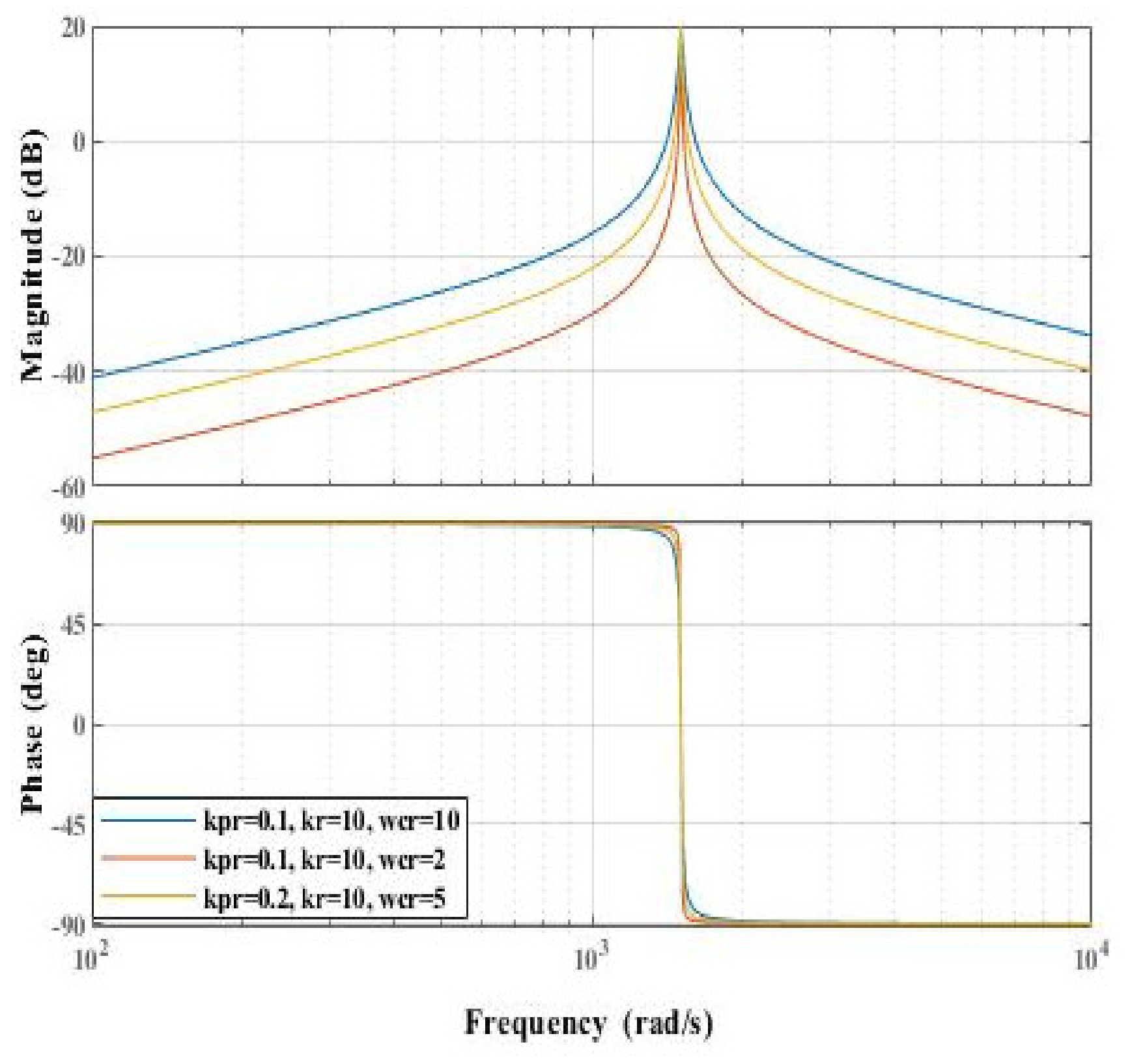
3.4. Parameter Design of the Proportional Resonant Filter

To reduce the sixth harmonic content in the currents i d and i q , a sixth harmonic resonant controller is proposed to be added to the current loop controller. The resonant frequency w 0 of this controller is determined based on the specific harmonic that needs to be compensated. Therefore, w 0 can be set to 6 w e to track the corresponding harmonic signals. This way, the harmonic compensation term only responds to signals around the frequency 6 w e , thus achieving compensation for the sixth harmonic.
This study further designs the parameters of the sixth harmonic quasi-proportional-resonant controller. With a set speed of 500 r/min and a frequency of 40 Hz, the corresponding sixth harmonic frequency is 240 Hz. Therefore, w 0 is set to 480π rad/s. The transfer function is expressed as follows:
G P R 6 ( s ) = k p 6 + 2 k r 6 ω c s s 2 + 2 ω c s + ( 480 π ) 2
As analyzed previously, the control parameters k p and k r influence the gain of the quasi-proportional-resonant controller. To achieve a gain of 38 dB at the resonant frequency w 0 in the current loop system, the parameters were set as follows: k p 6 at 0.1, 0.5, and 1, k p 6 at 80, and w c at 4 rad/s. The Bode plots for different parameter values are shown in Figure 3. From these plots, the following conclusions can be drawn:
  • When the proportional gain coefficient k p 6 decreases, the overall gain of the controller decreases, the phase margin increases, and the effect on bandwidth is minimal.
  • Increasing k p 6 enhances the gain at the resonant frequency, resulting in a faster dynamic response. Different values of k p 6 primarily affect the attenuation of frequency signals other than at the resonant point; the smaller k p 6 is, the lower the gain at other frequencies, but it does not impact the gain at the resonant point, thus having a minimal effect on bandwidth.
  • Increasing w c broadens the bandwidth of the resonant gain band without affecting the gain at the resonant point. Conversely, decreasing w c narrows the bandwidth of the resonant gain band, improving adaptability to frequency variations. Therefore, the cutoff frequency w c mainly influences the bandwidth of the controller; the smaller w c is, the better the frequency selection characteristics of the controller. However, due to current frequency fluctuations caused by harmonics in the AC drive system, a smaller w c results in greater gain fluctuations of the controller, making the system stability more susceptible to influence. Hence, the value of w c should not be too small.
Figure 3. Bode plot of the quasi-proportional-resonant controller with different parameter values.
Applsci 14 07206 g003
In this study, the bandwidth of the controller is adjusted by setting the cutoff frequency w c to accommodate frequency fluctuations. Based on the previous analysis, k p is set to 0.1 and k r is set to 80. The permissible speed fluctuation of the experimental motor is ±5 r/min, which corresponds to a frequency fluctuation of ±0.08 Hz. This fluctuation results in a sixth harmonic frequency fluctuation of ±0.48 Hz. To ensure that the controller maintains a gain of no less than 35 dB between 239.52 Hz and 240.48 Hz, the cutoff frequency w c should be no less than 1.47 rad/s. In this study, w c is set to 2 rad/s, and its Bode plot is shown in Figure 4.
Based on the previous analysis, to balance the filtering performance and dynamic performance of the system, this study selects k p r = 0.1 , k r = 80 , and w c r = 0.2 rad/s as control parameters.
By substituting the motor parameters L q = 2.45   m H and   R s = 1.6   into Equation (20) and selecting a gain value k s = 400 , the Bode plot of the system is obtained, as shown in Figure 5.
As shown in Figure 5, the system exhibits high gain at the resonant frequency while displaying significant gain attenuation at non-resonant frequencies. This result demonstrates the effectiveness of the proposed method in suppressing harmonic disturbances at the resonant frequency. The system maintains a narrow gain bandwidth at the resonant frequency point, allowing for more precise selection of response frequencies, enhancing robustness to frequency variations, and thereby improving overall system stability. Additionally, the appropriate proportional coefficient increases the gain across the entire frequency range, accelerating the dynamic response speed of the system. Therefore, the selection of these parameters effectively balances the filtering performance and dynamic performance of the system.

3.5. Stability Analysis

To ensure that the motion state points of the sliding mode observer approach and reach the selected sliding mode surface within an acceptable time frame, the Lyapunov stability condition must be satisfied. The Lyapunov function v is defined as follows:
V = 1 2 S T S = 1 2 ( S d 2 + S q 2 )
where S = S d S q T .
From Equation (22), the derivative of the Lyapunov function v can be derived, which is expressed as follows:
d V d t = S d d S d d t + S q d S q d t
Then, substituting Equations (14) and (16) into Equation (24) yields:
d V d t = s d ( ε d z d ( s d ) η t d s d ) + s q ( ε q z q ( s q ) η t q s q ) = ε d s d z d ( s d ) η t d s d 2 ε q s q z q ( s q ) η t q s q 2
Since   s d s i g n s d = s d and s q s i g n s q = s q , this expression can be further simplified:
d V d t = ε d | s d | η t d s d 2 ε q | s q | η t q s q 2
where η d s d 2 and η q s q 2 are clearly negative because η d and η q are positive control gains. Similarly, ε d s d   and ε q s q are also negative or zero because ε d and ε q are positive control gains, and s d and s q   are non-negative. Therefore, d V d t < 0. According to the Lyapunov stability theorem, if d V d t is negative definite, then the system state variables s d and s q are asymptotically stable.

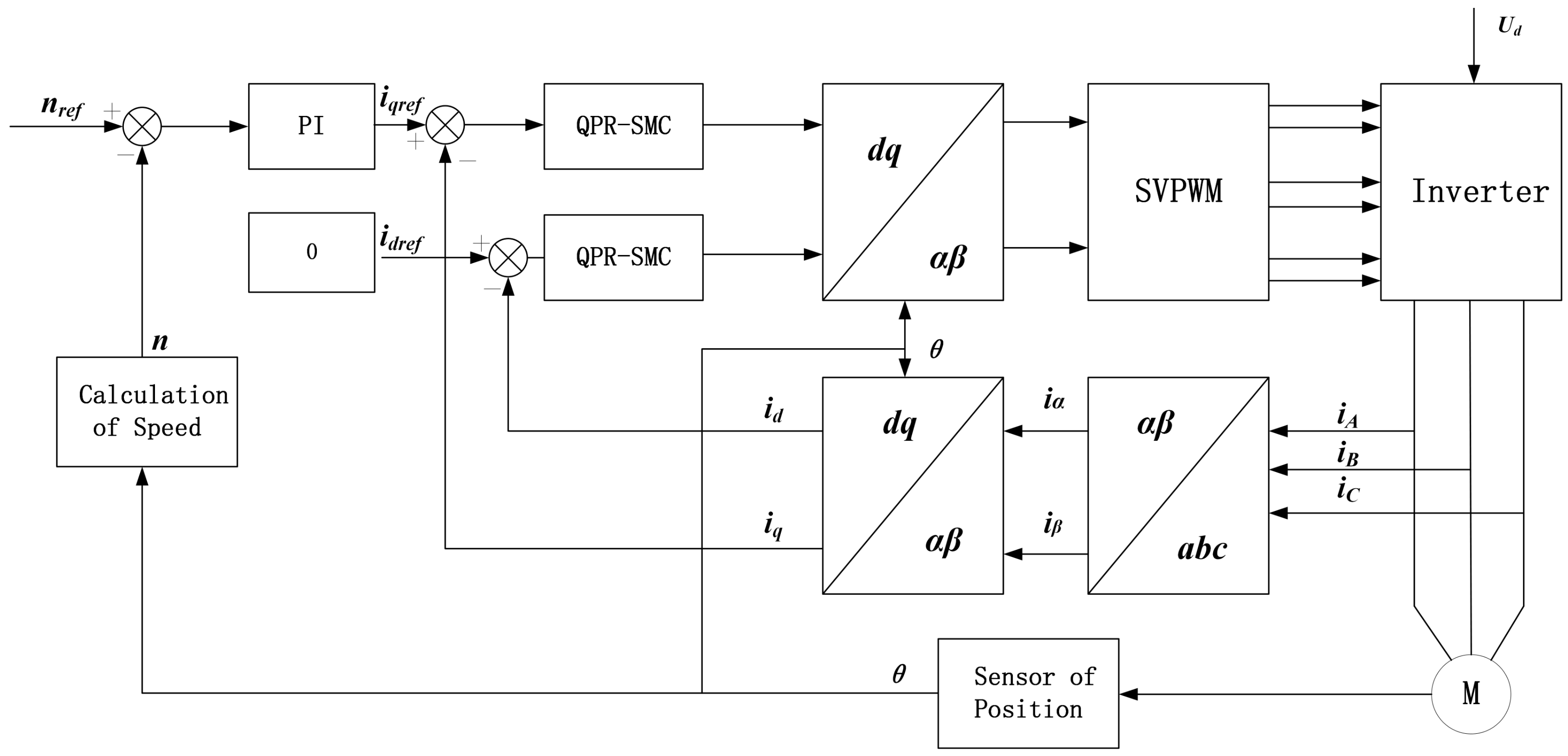
3.6. System Structure

The quasi-proportional-resonant sliding mode control (QPR-SMC) is integrated into the vector control of a PMSM drive system. In the two-phase stationary coordinate system, the control targets the harmonics with high harmonic content in the stator current of the PMSM. The fundamental angular frequency varies with the motor speed. The system control block diagram is shown in Figure 6. The system consists of a speed loop based on a PI regulator, a current loop based on dynamic harmonic compensation sliding mode control, and a coordinate transformation module.
Based on the current error-proportional resonant-sliding mode control switching surface equation shown in Equation (16), its structural block diagram can be derived, as illustrated in Figure 7. Taking the d-axis sliding mode switching surface as an example, its input is the current error, and its output is the new sliding mode control surface that combines the current error and harmonic compensation terms. The 5th and 7th harmonic currents in the stator current interacting with the fundamental magnetic field of the rotor permanent magnet will produce 6th-order torque ripples. Thus, the constructed current error-proportional resonant-sliding mode control switching surface effectively suppresses harmonics in the current by attenuating the 6th-order harmonics in the input current error.

4. Experimental Verification

To verify the correctness and effectiveness of the proposed dynamic harmonic compensation sliding mode control algorithm for harmonic current suppression, an experimental platform was established. The experimental setup includes a surface-mounted PMSM and its drive control system, as shown in Figure 8. The equipment used in the experiment includes a PMSM with a rated stator voltage of 24 V, a rated current of 10.0 A, four pole pairs, a rated speed of 3000 r/min, a stator resistance of 1.6 Ω, d-axis and q-axis inductances of 3.5 mH each, a magnetic flux linkage of 0.0593 Wb, and a rotor inertia of 2.45 × 10⁻⁴ kg·m2. The switching frequency is set to 10 kHz. The control system platform consists of two main parts: the power circuit and the control circuit. IGBTs are used as switching devices in the power circuit, and the core control chip is the STM32F103RCT6.
In the experiment, the total harmonic distortion (THD) of the 5th and 7th harmonic currents and the content of the 6th-order torque ripple were analyzed after applying the torque ripple suppression algorithm. These results were compared with the THD of the 5th and 7th harmonic currents and the content of the 6th-order torque ripple without the torque ripple suppression algorithm. The parameters of the quasi-proportional-resonant controller were set as follows: k p r = 0.1 , k r = 80 , and w c r = 0.2 rad/s.

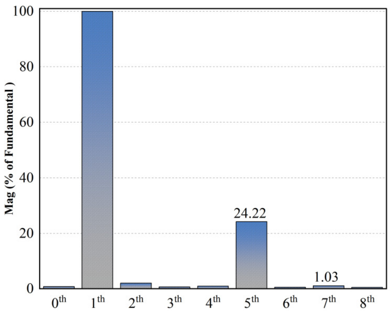
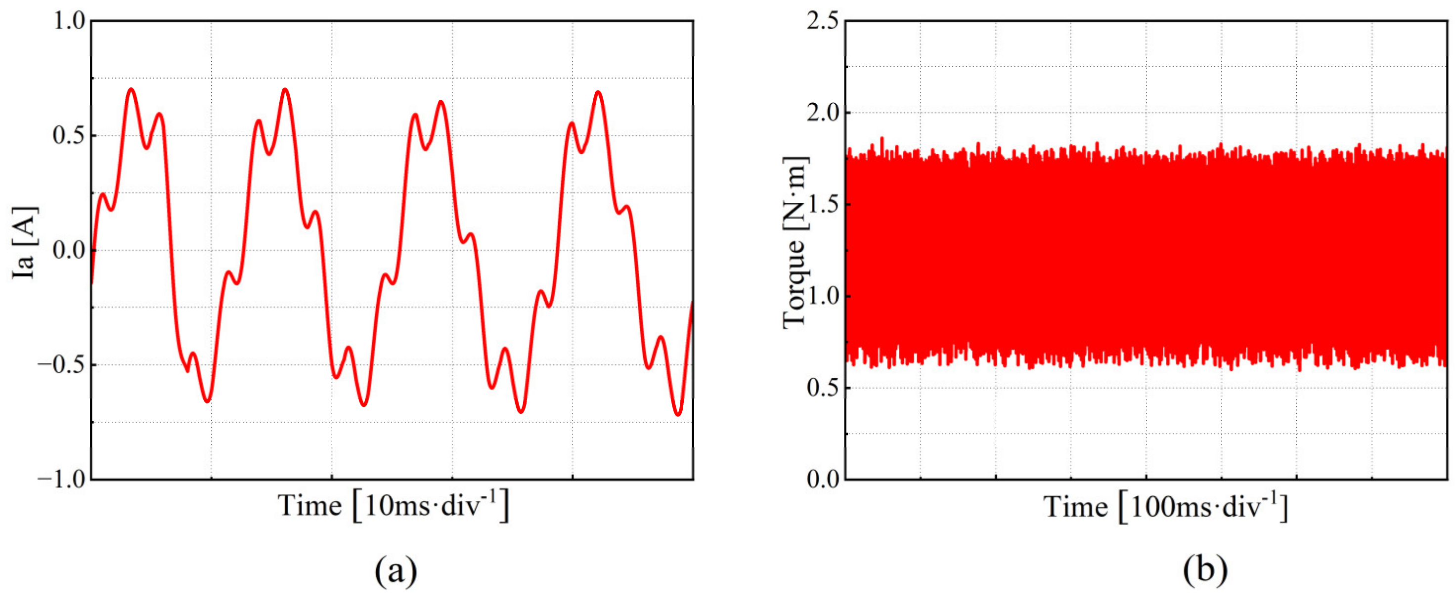
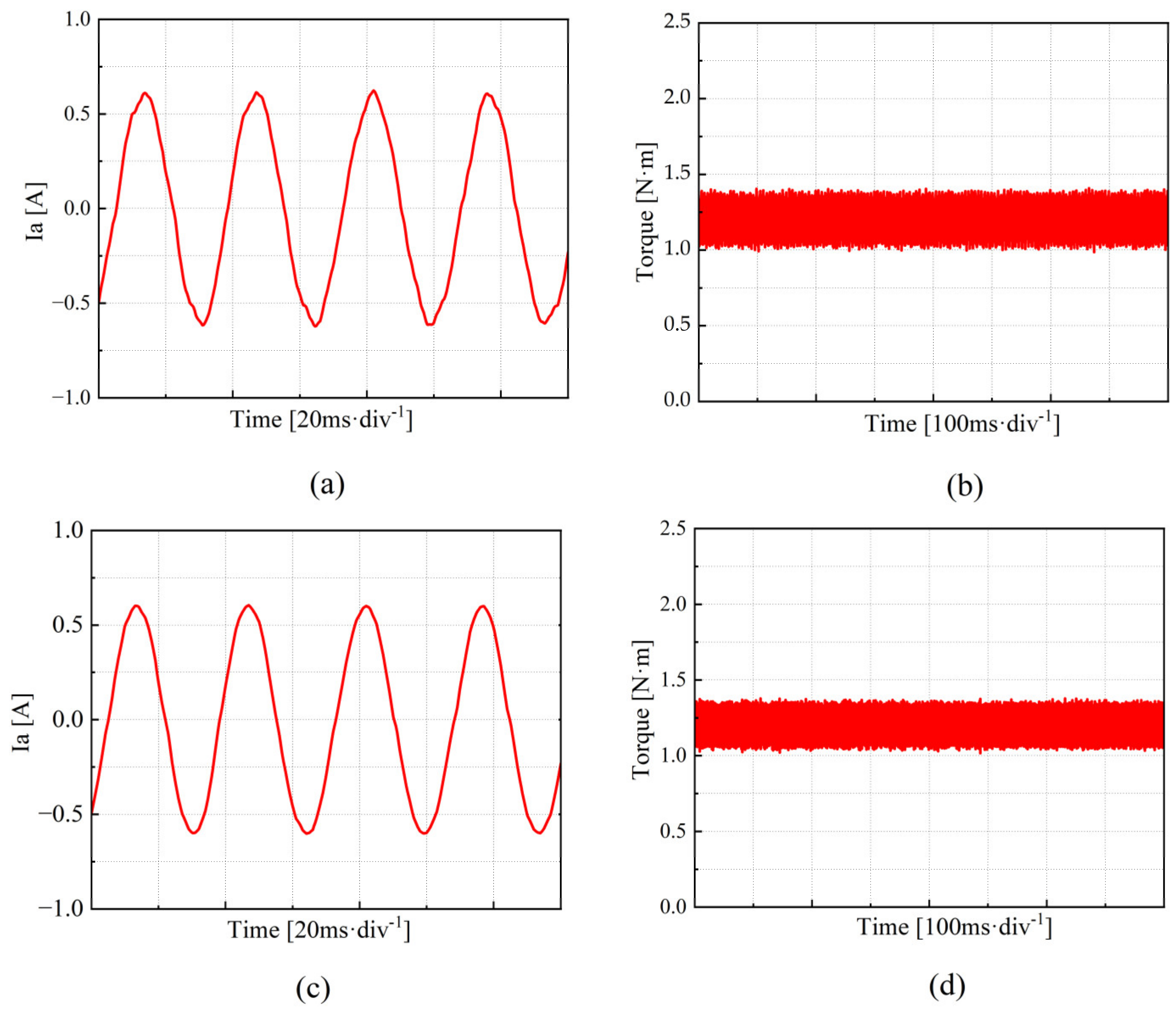
4.1. Analysis of the Performance of the Traditional PI Control Method in Current Harmonic Suppression

To evaluate the effectiveness of the traditional PI control method in suppressing current harmonics, experiments were conducted under three operating conditions: low speed, medium speed, and high speed. The harmonic components of the current and the torque ripple were analyzed for each condition.
Figure 9 shows the experimental results for the PMSM operating at a low speed (set speed of 450 r/min, motor current fundamental frequency of 30 Hz). As shown in Figure 9a, when using the traditional PI control method, the fifth harmonic component of the stator current accounts for 24.22%, the seventh harmonic component accounts for 1.03%, and the total harmonic distortion (THD) is 24.38%. Figure 9b indicates that the maximum torque ripple is 0.7%. Figure 10 demonstrates the frequency spectrum of the phase current at low speed.
Figure 11 presents the experimental results for the PMSM operating at a medium speed (set speed of 1125 r/min, motor current fundamental frequency of 75 Hz). As shown in Figure 11a, when using the traditional PI control method, the fifth harmonic component of the stator current accounts for 24.85%, the seventh harmonic component accounts for 1.66%, and the THD is 25.34%. Figure 11b shows that the maximum torque ripple is 1.05%. Figure 12 demonstrates the frequency spectrum of the phase current at medium speed.
Figure 13 provides the experimental results for the PMSM operating at a high speed (set speed of 2250 r/min, motor current fundamental frequency of 150 Hz). As shown in Figure 13a, when using the traditional PI control method, the fifth harmonic component of the stator current accounts for 25.11%, the seventh harmonic component accounts for 1.59%, and the THD is 25.66%. Figure 13b shows that the maximum torque ripple is 1.13%. Figure 14 demonstrates the frequency spectrum of the phase current at high speed.
The comparative analysis of the experimental results reveals that the traditional PI control method results in high harmonic content in the phase current under low, medium, and high-speed operating conditions. The sinusoidal quality of the current waveform is low, with noticeable waveform oscillations and significant distortions, which further exacerbate torque ripple.

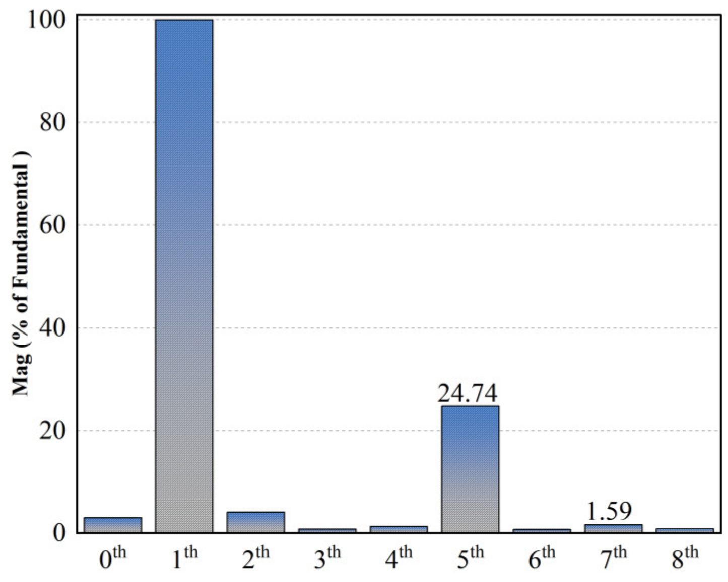
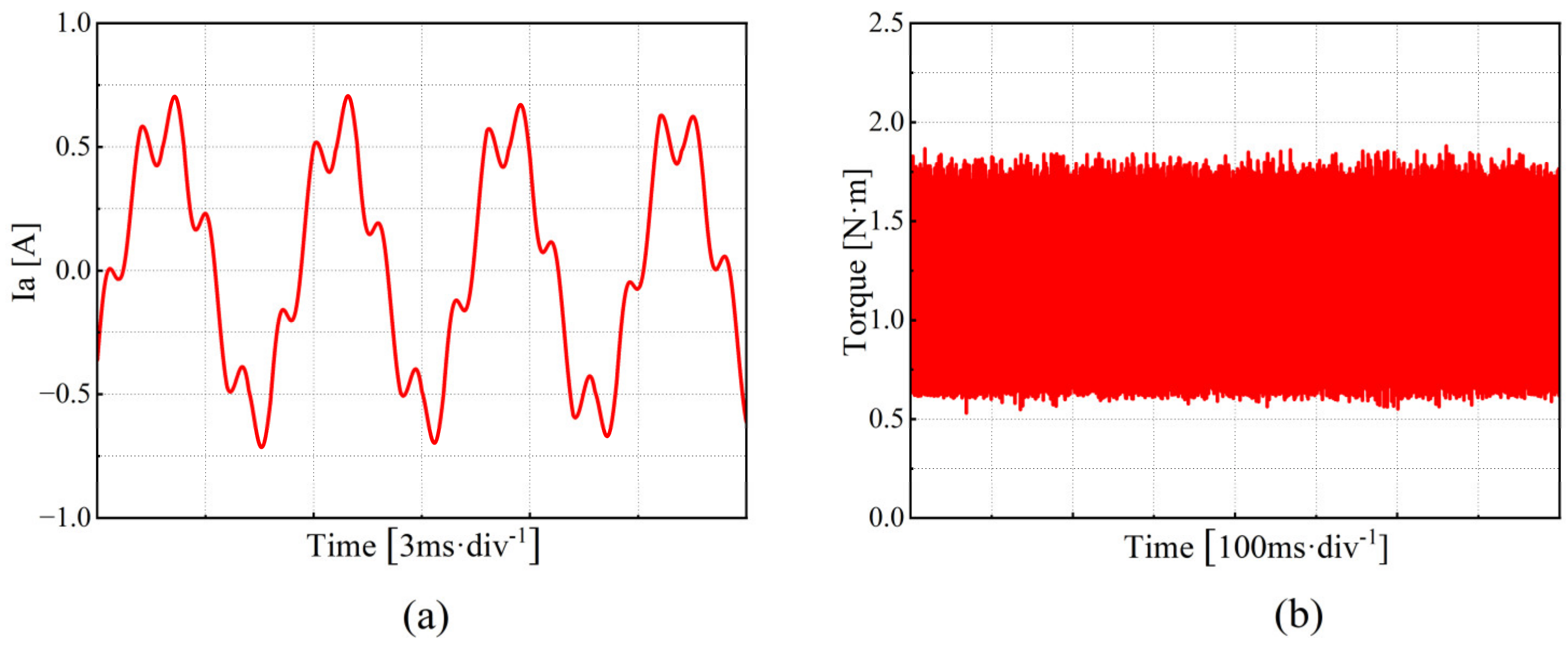
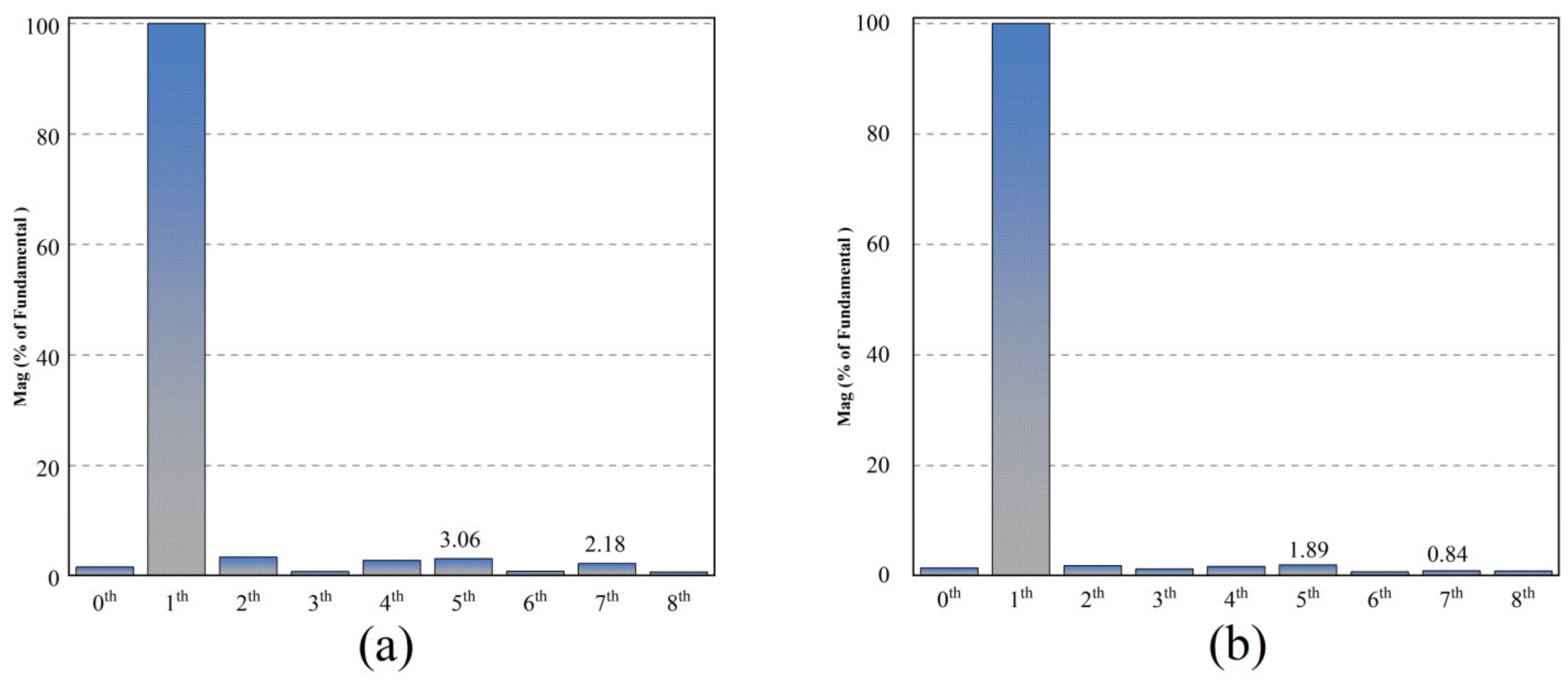
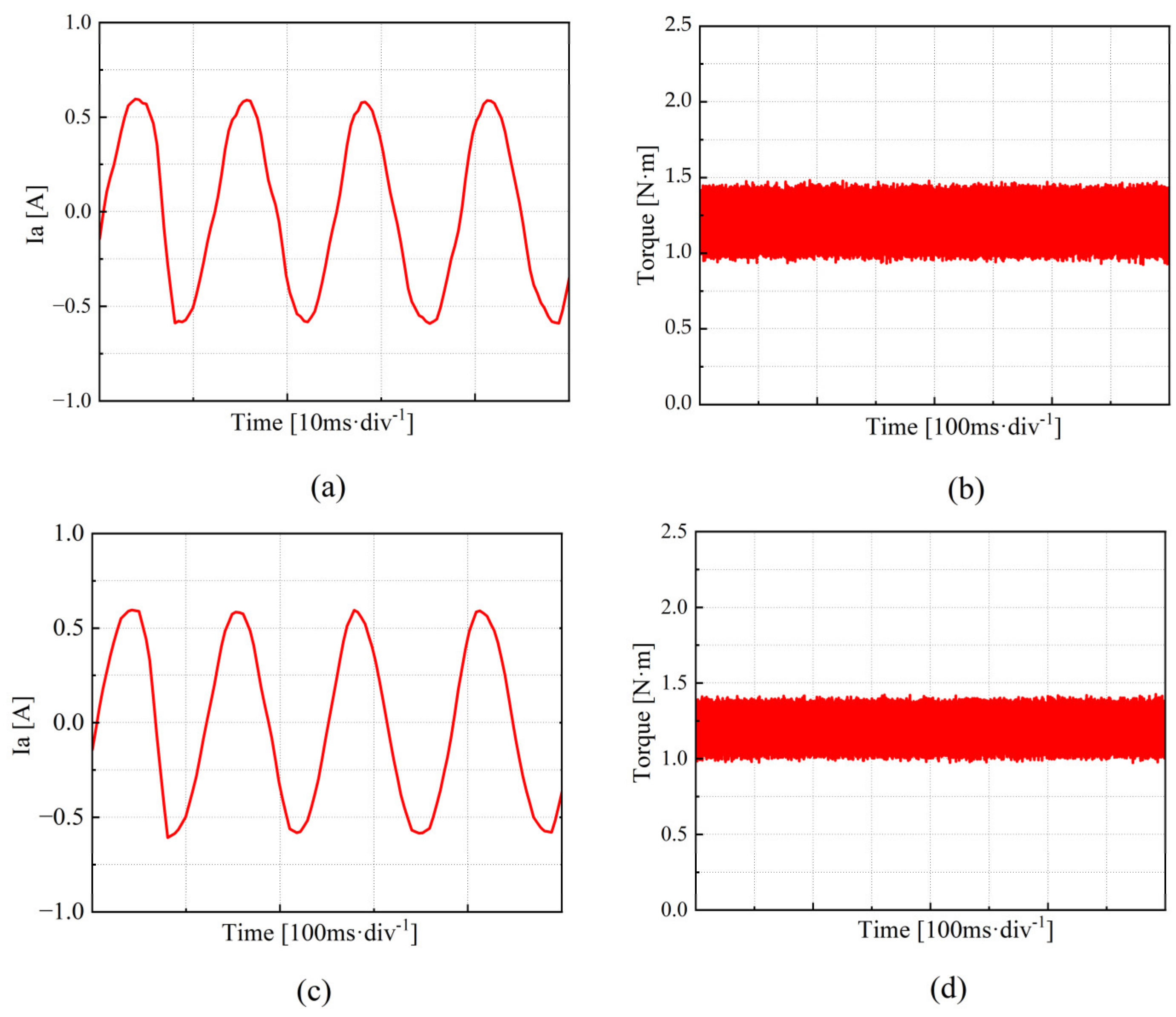
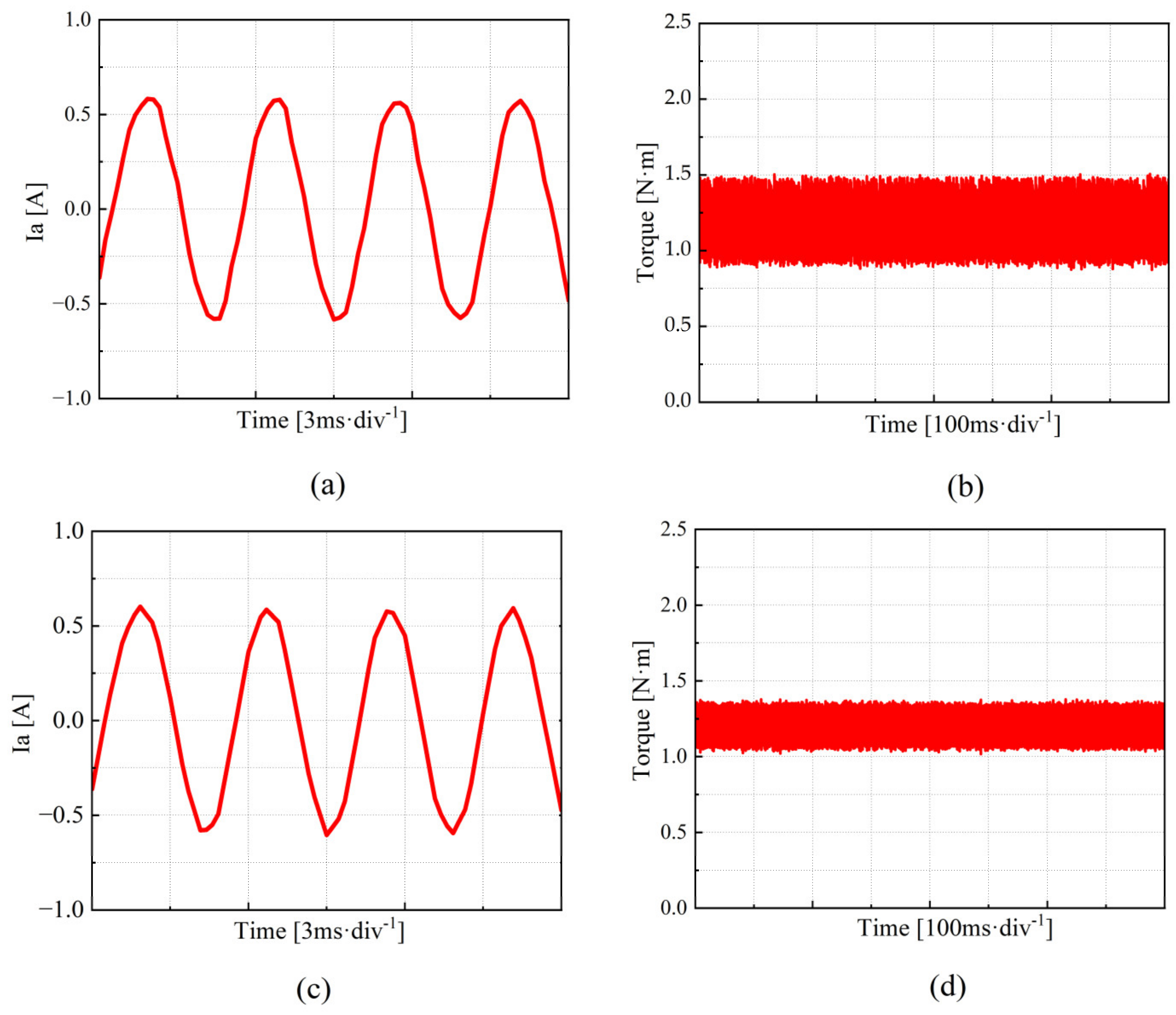
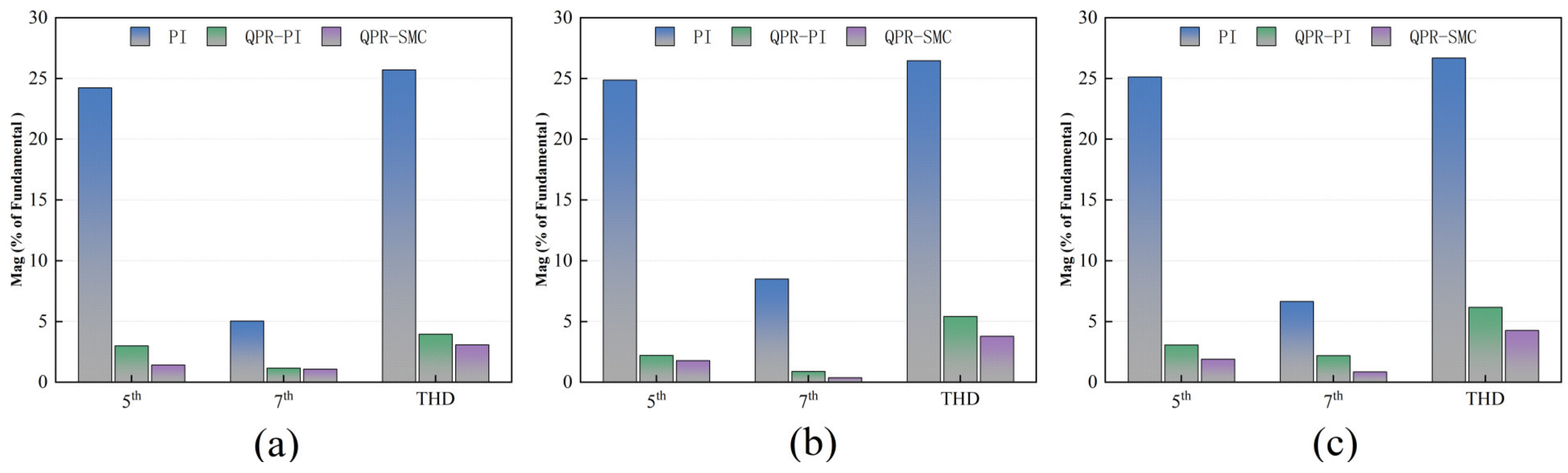
4.2. Comparison of QPR-PI and QPR-SMC Control Strategies in Current Harmonic Suppression Performance

To compare the effectiveness of the QPR-PI and QPR-SMC control strategies in suppressing current harmonics, this experiment was conducted under low-speed, medium-speed, and high-speed operating conditions. The harmonic components of the current and the torque ripple were analyzed for each condition.
Figure 15 shows the experimental results for the PMSM operating at a low speed (set speed of 450 r/min, motor current fundamental frequency of 30 Hz). As shown in Figure 15a, when using the QPR-PI and QPR-SMC control methods, the fifth harmonic component of the stator current accounts for 2.98% and 1.41%, respectively, while the seventh harmonic component accounts for 1.16% and 1.07%, respectively. The total harmonic distortion (THD) is 3.95% for QPR-PI and 3.07% for QPR-SMC. Figure 15b indicates that the maximum torque ripple is 0.45% for QPR-PI and 0.34% for QPR-SMC. As illustrated in Figure 16, the frequency spectrum of the phase current at low speed is presented for the QPR-PI control strategy and the QPR-SMC control strategy.
Figure 17 shows the experimental results for the PMSM operating at a medium speed (set speed of 1125 r/min, motor current fundamental frequency of 75 Hz). As illustrated in Figure 17a, when using the QPR-PI and QPR-SMC control methods, the fifth harmonic component of the stator current accounts for 2.19% and 1.77%, respectively, while the seventh harmonic component accounts for 0.88% and 0.37%, respectively. The total harmonic distortion (THD) is 5.41% for QPR-PI and 3.77% for QPR-SMC. Figure 17b indicates that the maximum torque ripple is 0.47% for QPR-PI and 0.37% for QPR-SMC. As illustrated in Figure 18, the frequency spectrum of the phase current at medium speed is presented for the QPR-PI control strategy and the QPR-SMC control strategy.
Figure 19 shows the experimental results for the PMSM operating at a high speed (set speed of 2250 r/min, motor current fundamental frequency of 150 Hz). As illustrated in Figure 19a, when using the QPR-PI and QPR-SMC control methods, the fifth harmonic component of the stator current accounts for 3.06% and 1.89%, respectively, while the seventh harmonic component accounts for 2.18% and 0.84%, respectively. The total harmonic distortion (THD) is 6.16% for QPR-PI and 4.25% for QPR-SMC. Figure 19b indicates that the maximum torque ripple is 0.55% for QPR-PI and 0.47% for QPR-SMC. As illustrated in Figure 20, the frequency spectrum of the phase current at high speed is presented for the QPR-PI control strategy and the QPR-SMC control strategy.
Figure 21 summarizes the data on the suppression effectiveness of PI, QPR-PI, and QPR-SMC control methods on the stator current harmonics and Total Harmonic Distortion (THD) in a PMSM under low-speed (450 r/min), medium-speed (1125 r/min), and high-speed (2250 r/min) operating conditions.
The results indicate that the traditional PI control method shows high harmonic content and THD at all speeds. At low speed, the fifth and seventh harmonic components are 24.22% and 5.03%, respectively, with a THD of 25.7%; at medium speed, the fifth and seventh harmonic components are 24.85% and 8.49%, respectively, with a THD of 26.45%; and at high speed, the fifth and seventh harmonic components are 25.11% and 6.64%, respectively, with a THD of 26.67%.
After introducing the QPR-PI control method, the harmonic content and THD significantly decreased. At low speed, the fifth and seventh harmonic components are reduced to 2.98% and 1.16%, respectively, with a THD of 3.95%; at medium speed, the fifth and seventh harmonic components are reduced to 2.19% and 0.88%, respectively, with a THD of 5.41%; and at high speed, the fifth and seventh harmonic components are reduced to 2.18% and 0.84%, respectively, with a THD of 6.16%.
The QPR-SMC control method further improves harmonic suppression. At low speed, the fifth and seventh harmonic components are reduced to 1.41% and 1.07%, respectively, with a THD of 3.07%; at medium speed, the fifth and seventh harmonic components are reduced to 1.77% and 1.00%, respectively, with a THD of 3.77%; and at high speed, the fifth and seventh harmonic components are reduced to 1.89% and 0.84%, respectively, with a THD of 4.25%.
By comparing the performance of the traditional PI control method, the QPR-PI control method, and the QPR-SMC control method at different speeds, the advantages and disadvantages of each control strategy in suppressing harmonics and reducing total harmonic distortion (THD) can be clearly understood. The following are the detailed comparative results of these three control methods under different speed conditions:
Before suppression, the fifth and seventh harmonic currents and the THD in the three-phase stator current of the motor were relatively high. After incorporating the proportional resonant controller, the fifth and seventh harmonic components and the THD in the current significantly decreased. Compared to the traditional PI control, the QPR-PI control also showed improvements in reducing harmonic components and THD, but it was not as effective as the QPR-SMC control. The QPR-SMC control strategy resulted in the lowest proportions of fifth and seventh harmonic components and THD under all conditions, indicating that the QPR-SMC control strategy can significantly improve current harmonic issues.
Based on these results, the following conclusions can be drawn: When the motor operates at different speeds, the corresponding fundamental electrical frequency and harmonic frequency change accordingly. The introduction of a frequency-adaptive proportional resonant controller allows the controller to adapt to speed variations and adjust the harmonic frequencies in real time. This effectively suppresses specific harmonic frequencies at different speeds, significantly reducing the harmonic components and THD in the stator current and markedly improving the torque ripple of the motor.

5. Conclusions

The output voltage of inverters is affected by nonlinear factors such as dead time and voltage drops, which inject low-order harmonics, causing fifth and seventh harmonic distortions in the stator current and inducing periodic torque ripple. This significantly impacts the control precision of PMSM. To address this issue, this paper proposes a control strategy based on dynamic harmonic compensation sliding mode control. This method improves the harmonic suppression performance of the motor drive system, yielding effective results, and leads to the following conclusions:
  • The resonant frequency of the proportional resonant controller can be designed and adjusted as needed, allowing for selective suppression of harmonics at specific frequencies without causing distortion at other frequencies.
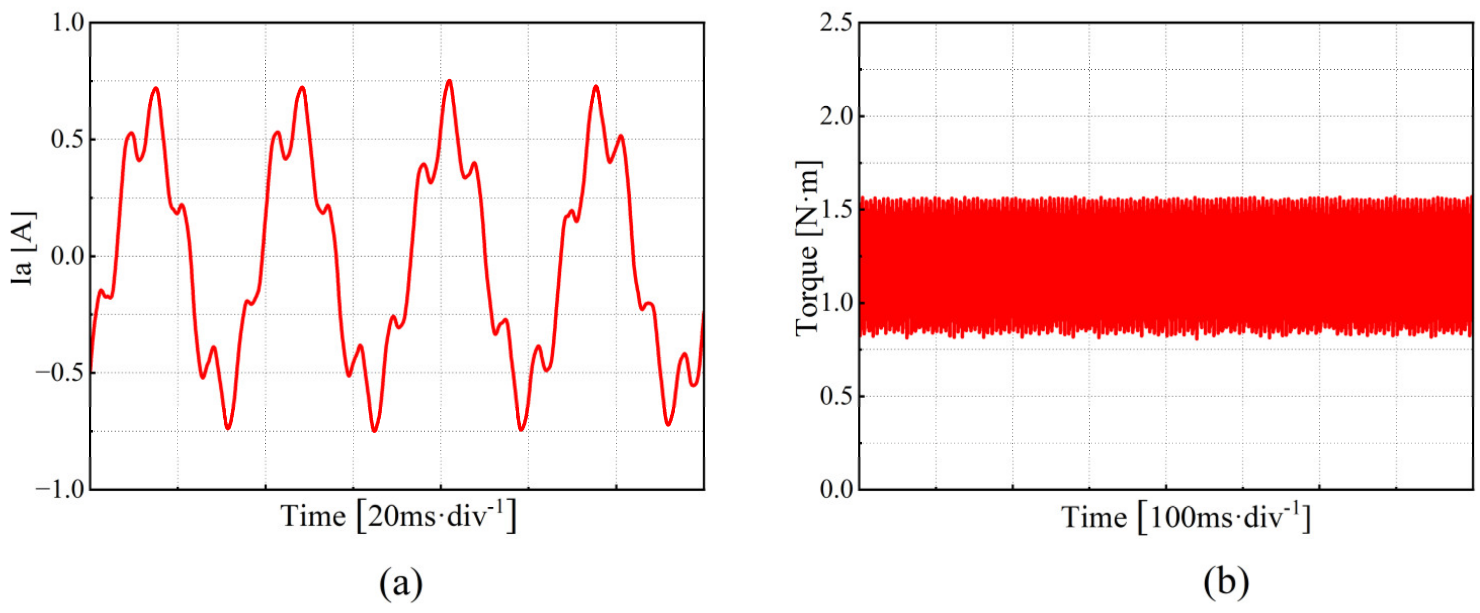
  • Traditional QPR-PI controllers have limited effectiveness in dealing with nonlinear disturbances such as dead time and voltage drops, which introduce harmonics, thereby affecting current harmonic suppression. Compared to the traditional QPR-PI feedforward compensation method, the QPR-SMC method results in lower harmonic content and provides better current harmonic suppression, making the stabilized current waveform closely resemble the ideal sinusoidal waveform.
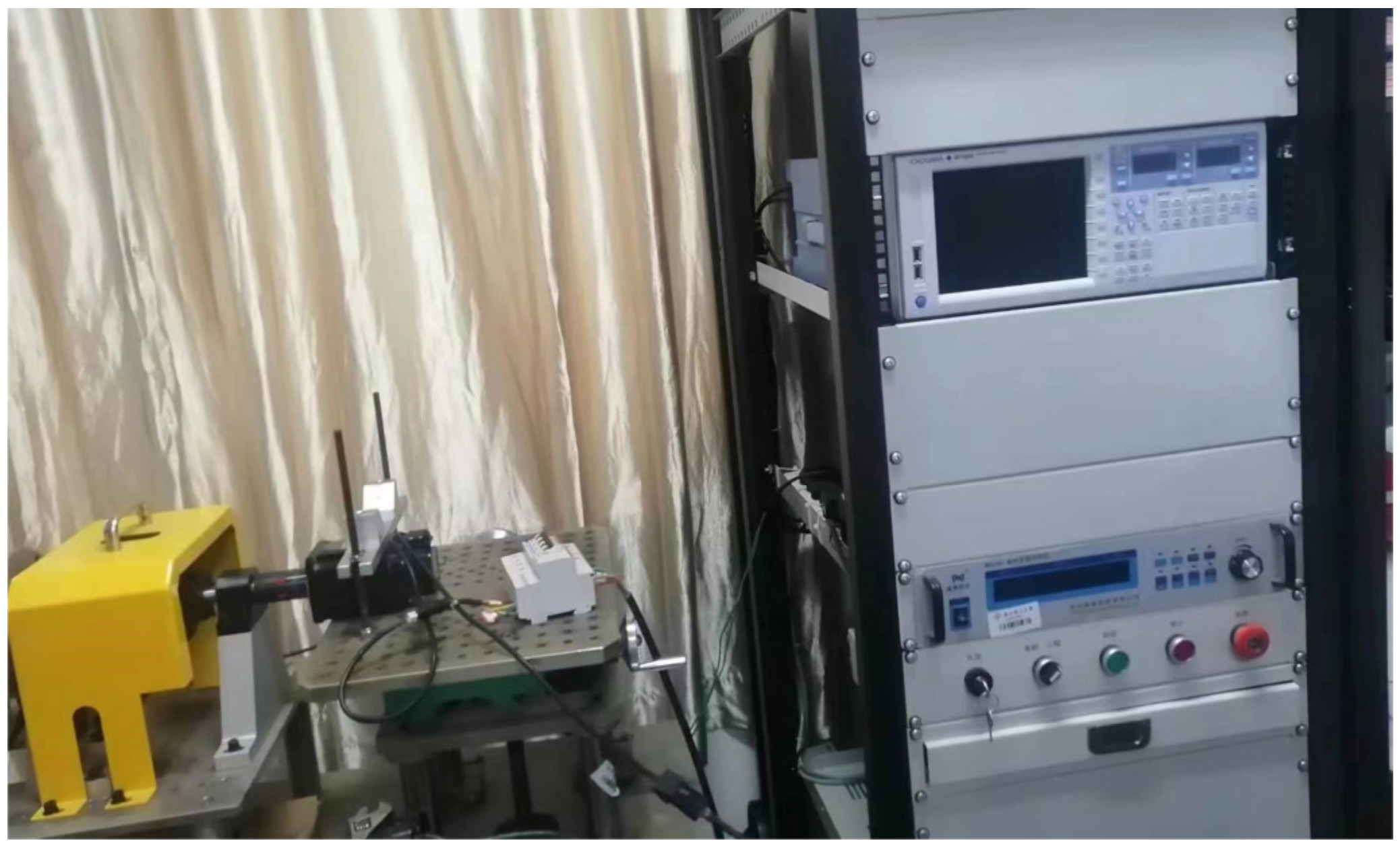
  • To verify the correctness of the proposed scheme, a corresponding test platform was established, and comparative experiments were conducted. The results show that this method can adaptively cancel the sixth harmonic component in the stator voltage in the d–q axis system, successfully reducing the fifth and seventh harmonic components in the three-phase current, and significantly mitigating motor torque ripple.

Author Contributions

K.W. and Y.Z. designed the proposed control strategy and experiments. W.S. conducted the experiments and organized the data. W.L. and Y.Q. wrote the manuscript. All authors have read and agreed to the published version of the manuscript.

Funding

This work was supported in part by the National Natural Science Foundation of China under Grant 52277068 and in part by the Key Research and Development Program of the Zhejiang Science and Technology Department under Grants 2024C01230 and 2023C01159.

Institutional Review Board Statement

Not applicable.

Informed Consent Statement

Not applicable.

Data Availability Statement

Data is contained within the article.

Acknowledgments

This research was partially supported by the National Natural Science Foundation of China and the Key Research and Development Program of the Zhejiang Science and Technology Department. We express our sincere gratitude for their support, which was crucial for the successful completion of this study.

Conflicts of Interest

The authors declare no conflicts of interest.

References

  1. Khanh, P.Q.; Anh, H.P.H. Hybrid optimal fuzzy Jaya technique for advanced PMSM driving control. Electr. Eng. 2023, 105, 3629–3646. [Google Scholar] [CrossRef]
  2. Rafaq, M.S.; Midgley, W.; Steffen, T. A Review of the State of the Art of Torque Ripple Minimization Techniques for Permanent Magnet Synchronous Motors. IEEE Trans. Ind. Inform. 2024, 20, 1019–1031. [Google Scholar] [CrossRef]
  3. Minghe, T.; Bo, W.; Yong, Y.; Xing, M.; Qinghua, D.; Dianguo, X. Proportional resonant-based active disturbance rejection control for speed fluctuation suppression of PMSM drives. In Proceedings of the 2019 22nd International Conference on Electrical Machines and Systems (ICEMS), Harbin, China, 1–14 August 2019; IEEE: Piscataway, NJ, USA, 2019; pp. 1–6. [Google Scholar]
  4. Wu, L.; Chen, H.; Yu, T.; Sun, C.; Wang, L.; Ye, X.; Zhai, G. Robust Design Optimization of the Cogging Torque for a PMSM Based on Manufacturing Uncertainties Analysis and Approximate Modeling. Energies 2023, 16, 663. [Google Scholar] [CrossRef]
  5. Wang, Y.; Gao, Y.; Zhao, C.; Li, X. Iterative Learning Based Torque Ripple Suppression of Flux-Modulation Double-Stator Machine. IEEE Trans. Ind. Electron. 2022, 69, 6645–6656. [Google Scholar] [CrossRef]
  6. Li, Z.; Kong, W.; Cheng, Y.; Qu, R. An Iterative Learning Based Direct Torque Control Strategy of DC-Biased Vernier Reluctance Machines for Torque Ripple Reduction. IEEE Trans. Power Electron. 2023, 38, 15456–15466. [Google Scholar] [CrossRef]
  7. Bi, G.; Zhang, G.; Wang, G.; Wang, Q.; Hu, Y.; Xu, D. Adaptive Iterative Learning Control-Based Rotor Position Harmonic Error Suppression Method for Sensorless PMSM Drives. IEEE Trans. Ind. Electron. 2022, 69, 10870–10881. [Google Scholar] [CrossRef]
  8. Li, H.; Guo, Y.; Xu, Q. PMSM Torque Ripple Suppression Method Based on SMA-Optimized ILC. Sensors 2023, 23, 9317. [Google Scholar] [CrossRef]
  9. Qing, H.; Zhang, C.; Chai, X.; He, H.; Wang, X. Research on grid-connected harmonic current suppression of three-phase four-wire energy storage inverters. J. Power Electron. 2023, 23, 972–983. [Google Scholar] [CrossRef]
  10. Li, J.; Chen, P.; Pan, Y.; Liu, J.; Chen, Q.; Cui, P. High-Precision Suppression of Harmonic Vibration Force by Repetitive Controller With Triple-Loop Structure. IEEE Trans. Power Electron. 2023, 38, 10821–10828. [Google Scholar] [CrossRef]
  11. Cai, K.; Deng, Z.; Peng, C.; Li, K. Suppression of Harmonic Vibration in Magnetically Suspended Centrifugal Compressor Using Zero-Phase Odd-Harmonic Repetitive Controller. IEEE Trans. Ind. Electron. 2020, 67, 7789–7797. [Google Scholar] [CrossRef]
  12. Zhang, Y.; Zhou, J.; Han, X.; Zhou, Y. Adaptive odd repetitive control for magnetically suspended rotor harmonic currents suppression. J. Vib. Control 2023, 29, 2077–2085. [Google Scholar] [CrossRef]
  13. Li, D.; Zhao, D. Single Current Feedback Control Strategy of an LCL Grid-Connected Inverter Based on GI-ESO and Delay Compensation. Energies 2022, 15, 2893. [Google Scholar] [CrossRef]
  14. Chen, Y.; Zhang, X.; Yang, J.; Yan, L.; Deng, R. Smooth and Robust Current Control of PMSMs With Decoupling-Type Extended State Observers. IEEE Trans. Ind. Electron. 2023, 71, 10377–10388. [Google Scholar] [CrossRef]
  15. Memije Garduno, D.; Rodriguez Rivas, J.J.; Carranza Castillo, O.; Ortega Gonzalez, R.; Rodarte Gutierrez, F.E. Current Distortion Rejection in PMSM Drives Using an Adaptive Super-Twisting Algorithm. IEEE Trans. Energy Convers. 2022, 37, 927–934. [Google Scholar] [CrossRef]
  16. Li, Y.; Hu, Y.; Zhu, Z.Q. Current Harmonics and Unbalance Suppression of Dual Three-Phase PMSM Based on Adaptive Linear Neuron Controller. IEEE Trans. Energy Convers. 2023, 38, 2353–2363. [Google Scholar] [CrossRef]
  17. Chu, Y.; Hou, S.; Wang, C.; Fei, J. Recurrent-Neural-Network-Based Fractional Order Sliding Mode Control for Harmonic Suppression of Power Grid. IEEE Trans. Ind. Inform. 2023, 19, 9979–9990. [Google Scholar] [CrossRef]
  18. Chen, G.; Xu, L. Adaptive quasi-proportional resonant control with parameter estimation for PMSM sensorless control. Adv. Mech. Eng. 2023, 15, 16878132231154069. [Google Scholar] [CrossRef]
  19. Xie, F.; Xu, J.; Shen, M.; Zheng, Z. Current harmonic suppression strategy for permanent magnet synchronous motor based on small phase angle resonant controller. IET Electr. Power Appl. 2024, 18, 556–564. [Google Scholar] [CrossRef]
  20. Cao, H.; Deng, Y.; Li, H.; Wang, J.; Liu, X.; Sun, Z.; Yang, T. Generalized Active Disturbance Rejection With Reduced-Order Vector Resonant Control for PMSM Current Disturbances Suppression. IEEE Trans. Power Electron. 2023, 38, 6407–6421. [Google Scholar] [CrossRef]
  21. Zhang, Q.; Guo, H.; Guo, C.; Liu, Y.; Wang, D.; Lu, K.; Zhang, Z.; Zhuang, X.; Chen, D. An adaptive proportional-integral-resonant controller for speed ripple suppression of PMSM drive due to current measurement error. Int. J. Electr. Power Energy Syst. 2021, 129, 106866. [Google Scholar] [CrossRef]
  22. Pal, K.; Kumar, S.; Singh, B.; Kandpal, T.C. Enhanced resonant two-degree of freedom-based PID controller for grid-integrated PV power generating system. IET Renew. Power Gener. 2020, 14, 3550–3557. [Google Scholar] [CrossRef]
  23. Lyu, J.; Yan, Y.; Wu, F.; Sun, Z.; Farooq, A.; Xu, W. Parameter co-design of active damping loop and grid current controller for a 3-phase LCL-filtered grid-connected inverter. Int. J. Electr. Power Energy Syst. 2021, 133, 107203. [Google Scholar] [CrossRef]
Figure 1. Bode plot of the ideal resonant controller and the quasi-resonant controller.
Applsci 14 07206 g001
Figure 2. Principles of harmonic suppression based on QPR.
Applsci 14 07206 g002
Figure 4. Bode plot of the quasi-proportional-resonant controller with k p   = 0.1, k r   = 80, and w c   = 2 rad/s.
Applsci 14 07206 g004
Figure 5. Bode plot of the system.
Applsci 14 07206 g005
Figure 6. A system control block diagram.
Applsci 14 07206 g006
Figure 7. A structural block diagram of the current error-proportional resonant-sliding mode control surface.
Applsci 14 07206 g007
Figure 8. The motor drive test platform.
Applsci 14 07206 g008
Figure 9. Phase current and load torque waveforms at low speed (450 r/min). (a) Phase current waveform. (b) Load torque waveform.
Applsci 14 07206 g009
Figure 10. Frequency spectrum of the phase current at low speed.
Applsci 14 07206 g010
Figure 11. Phase current and load torque waveforms at low speed (1125 r/min). (a) Phase current waveform. (b) Load torque waveform.
Applsci 14 07206 g011
Figure 12. Frequency spectrum of the phase current at medium speed.
Applsci 14 07206 g012
Figure 13. Phase current and load torque waveforms at low speed (2250 r/min). (a) Phase current waveform. (b) Load torque waveform.
Applsci 14 07206 g013
Figure 14. Frequency spectrum of the phase current at high speed.
Applsci 14 07206 g014
Figure 15. Phase current and torque waveforms at low speed (450 r/min) under the QPR-PI and QPR-SMC control strategies. (a) Phase current waveform under the QPR-PI control strategy. (b) Torque waveform under the QPR-PI control strategy. (c) Phase current waveform under the QPR-SMC control strategy. (d) Torque waveform under the QPR-SMC control strategy.
Applsci 14 07206 g015
Figure 16. Frequency spectrum of the phase current at low speed: (a) under the QPR-PI control strategy; (b) under the QPR-SMC control strategy.
Applsci 14 07206 g016
Figure 17. Phase current and torque waveforms at low speed (1125 r/min) under the QPR-PI and QPR-SMC control strategies. (a) Phase current waveform under the QPR-PI control strategy. (b) Torque waveform under the QPR-PI control strategy. (c) Phase current waveform under the QPR-SMC control strategy. (d) Torque waveform under the QPR-SMC control strategy.
Applsci 14 07206 g017
Figure 18. Frequency spectrum of the phase current at medium speed: (a) under the QPR-PI control strategy; (b) under the QPR-SMC control strategy.
Applsci 14 07206 g018
Figure 19. Phase current and torque waveforms at low speed (2250 r/min) under the QPR-PI and QPR-SMC control strategies. (a) Phase current waveform under the QPR-PI control strategy. (b) Torque waveform under the QPR-PI control strategy. (c) Phase current waveform under the QPR-SMC control strategy. (d) Torque waveform under the QPR-SMC control strategy.
Applsci 14 07206 g019
Figure 20. Frequency spectrum of the phase current at high speed: (a) under the QPR-PI control strategy; (b) under the QPR-SMC control strategy.
Applsci 14 07206 g020
Figure 21. Harmonic analysis results for PI, QPR-PI, and QPR-SMC control methods at different speeds: (a) Suppression results at low speed; (b) Suppression results at medium speed; (c) Suppression results at high speed.
Applsci 14 07206 g021
Disclaimer/Publisher’s Note: The statements, opinions and data contained in all publications are solely those of the individual author(s) and contributor(s) and not of MDPI and/or the editor(s). MDPI and/or the editor(s) disclaim responsibility for any injury to people or property resulting from any ideas, methods, instructions or products referred to in the content.

