Article

Optimizing Sustainable Thread Design for Motorized Leg-Lengthening Devices: A Structural and Performance Assessment

1
College of Engineering, Science and Environment, University of Newcastle, Callaghan, NSW 2308, Australia
2
Engineering Cluster, Singapore Institute of Technology, Singapore 138683, Singapore
3
Engineering Product Development, Science, Mathematics and Technology, Singapore University of Technology and Design, Singapore 487372, Singapore
*
Authors to whom correspondence should be addressed.
Appl. Sci. 2024, 14(16), 7296; https://doi.org/10.3390/app14167296
Submission received: 27 June 2024 / Revised: 15 August 2024 / Accepted: 16 August 2024 / Published: 19 August 2024
(This article belongs to the Section Mechanical Engineering)

Abstract

:
This study offers an in-depth structural analysis of the threading mechanism in a motorized leg-lengthening nail, a key device used in bone-lengthening surgeries. The primary aim is to assess the structural integrity and performance of the nail during the lengthening process. The paper starts with a comprehensive overview of the nail’s design, historical background, and functionality, emphasizing the critical components of the lengthening mechanism. The methodology section details the structural analysis approach, incorporating both finite element analysis (FEA) and manual calculations. FEA simulations are employed to analyze the nail’s behavior under compressive loads, considering realistic conditions such as the 95th percentile of human body weight. The analysis focuses on stress concentrations, deflections, and overall structural stability to pinpoint the potential weaknesses. Due to budget limitations that prevented the creation of physical prototypes, manual calculations were utilized to validate the FEA results. The findings identify stress concentrations, especially in the areas where male and female threads engage, leading to the design of recommendations to enhance strength and reliability. Experimental results corroborate the accuracy of the FEA simulations. The study concludes with suggestions for improving thread design, emphasizing safety, durability, and functionality. These recommendations aim to guide the future iterations of the motorized leg-lengthening nail, thereby promoting the development of safer and more effective devices for bone-lengthening surgeries. This structural analysis significantly contributes to understanding the mechanical behavior of the motorized leg-lengthening nail, playing a crucial role in advancing medical devices for bone-lengthening procedures.

1. Introduction

The motorized intramedullary lengthening nail, an advancement over the previous external leg-lengthening device, assists in leg-lengthening procedures [1]. However, the instances of the nail failing to extend after implantation have been reported. These failures can be attributed to various factors, which are broadly categorized into electrical and mechanical issues. This report reviews the mechanical failure points of motorized intramedullary lengthening nails, focusing specifically on a comprehensive structural analysis of the thread. The aim is to identify the causes of the screw engagement area becoming stuck during extension and to determine the location of maximum stress within the screw thread. Additionally, the study aims to calculate the torque required to rotate the thread, thereby enhancing the understanding of the mechanical aspects involved. Material selection is critical, and the project seeks to determine the most suitable material for the leg-lengthening nail. Further optimization involves identifying the best thread engagement leg and pitch configuration. Results from Finite Element Analysis (FEA) simulations will be validated through hand calculations for bearing stress, ensuring accuracy. The project will include detailed research on the mechanism of the motorized intramedullary lengthening nail, supported by 3D CAD version V13.1 drawings of each component for a mock-up. FEA analysis using SolidWorks will be performed on a simplified model, focusing on the critical thread engagement area. The study will simulate three different materials and various thread engagement lengths and pitches. A comparison between FEA simulation results and those from tensile testing and calculations will provide a comprehensive evaluation of the design’s mechanical performance. This project aims to offer valuable insights for optimizing and improving the motorized intramedullary lengthening nail. Until the late 1980s, individuals outside the Union of Soviet Socialist Republics (USSR) with limb length discrepancies caused by poorly healed fractures, diseases, or congenital issues had limited treatment options. The pioneering Ilizarov method, developed in Russia over fifty years ago, now provides a means to address these discrepancies and related deformities [2]. The history of limb lengthening devices dates back to Gavriil Ilizarov’s 1954 mechanism. Ilizarov, a Russian orthopedic surgeon, invented the external fixation method for limb lengthening to treat patients suffering from polio, congenital limb defects, or dwarfism [3]. According to Dr. Vuillermin, limb lengthening is a procedure that promotes bone growth in a patient’s tibia or femur, making it longer. This is achieved by surgically cutting the bone and attaching a device that gradually separates the two ends. As the gap increases, new bone forms and fills the space. Depending on factors like age, growth stage, and the required lengthening, patients may undergo multiple cycles of lengthening over several years. The primary goal of limb lengthening is to correct leg length discrepancies, thereby achieving bodily balance and preventing issues in the back, hips, and knees that can result from walking with legs of different lengths [4].
Motorized intramedullary lengthening nails have been used for three decades, marking a significant improvement over external fixators by reducing the risk of pin site infections and enhancing patient comfort during the limb lengthening process. Moreover, internal nails allow patients to engage in weight-bearing activities earlier in their treatment. In a review of 377 patients who underwent limb lengthening, 40 devices experienced mechanical failures, with over half requiring additional corrective surgeries. Specifically, 16 devices failed during the lengthening phase [5]. Given this failure rate, further studies are necessary to investigate the mechanical characteristics and the pros and cons of intramedullary lengthening nails. One common method for inserting the lengthening nail involves entering through the upper part of the femur, near the hip, in a procedure known as antegrade insertion. This process includes making skin incisions and possibly cutting the bone at the osteotomy site for lengthening [6]. Once inserted, the lengthening process begins and can extend up to a maximum of 80 mm, depending on the patient’s requirements. The lengthening duration correlates with the length requirement, the greater the required length, the longer the process. During weight-bearing activities such as standing, walking, and physical exercise, mechanical loading occurs on the bones, stimulating bone cells called osteoblasts responsible for bone formation. Controlled stress or load increases bone density and strength, making weight-bearing exercises essential for maintaining strong bones. In limb lengthening, all weight loading is borne by the intramedullary lengthening nails. The global average adult human mass is approximately 136.7 pounds (62.14 kg) [7]. Understanding average human mass is crucial in the design and use of limb lengthening devices, as it affects the mechanical load the limbs must bear during lengthening. These devices work by gradually separating the bone at the desired length and allowing new bone and soft tissue to form in the gap. Body weight and mass distribution significantly influence the stresses on the lengthened limb, making it essential to consider factors such as the patient’s mass, the location of the lengthening, and the rate of distraction. Maintaining a healthy body weight is important for both patients and healthcare providers to ensure successful limb lengthening outcomes. Materials used for medical implants must meet stringent requirements for their safe integration into the human body, including biocompatibility, corrosion resistance, mechanical strength, inertness, and radiopacity. The selection of materials for orthopedic implants and surgical instruments is meticulous, with titanium and stainless steel being preferred due to their exceptional properties. Stainless steel is ideal for its strength, corrosion resistance, and biocompatibility, ensuring durability and minimizing adverse reactions in the challenging environments that these devices encounter. Titanium and its alloys are also highly regarded for their biocompatibility, low density, and robustness, making them excellent choices for orthopedic and dental implants. The careful selection of these materials prioritizes patient well-being and advances healthcare outcomes by ensuring their successful integration within the human body [8].

2. Methodology

The project begins with scheduled Finite Element Analysis (FEA) tests, starting with the creation of a 3D engineering drawing of the intramedullary nail for visual analysis. Next, a simplified test rig is developed specifically for thread simulation testing, involving tensile loading with torque. This approach aims to first evaluate the structural aspects through FEA, providing a visual understanding of the design. Subsequently, the simulation testing on the thread in the simplified test rig enables a more focused assessment of its performance under tensile loading conditions, incorporating the influence of torque. This ensures a comprehensive examination of both the overall design and the specific thread behavior, offering valuable insights for the project’s objectives. The research methodology for this project involves a multi-step approach to investigate limb lengthening devices, understanding the mechanical failures during the consolidation phase, and propose potential improvements in design and material selection. The examination of the provided intramedullary nail, as shown in Figure 1, is a crucial component of a thorough analysis aimed at addressing the potential occurrence of thread failure during the critical consolidation phase of orthopedic recovery. This phase is vital for the healing process of fractures, with intramedullary nails providing necessary structural support and alignment to facilitate successful bone fusion. However, thread failure within these devices can lead to severe consequences, compromising both the structural integrity of the bone and the overall success of the surgical procedure. The visual representations in Figure 1 illustrate the original provided intramedullary nail, allowing for an initial assessment of its design and dimensions. These visual aids are essential for understanding the broader aspects of the nail’s construction, including the characteristics of the threads, their pitch, depth, and how they interact with the surrounding structure.

2.1. Engineering Drawing

Given the thread failures observed during the consolidation phase, a more detailed and focused analysis is essential. The next step involves creating a 3D engineering drawing of the intramedullary nail using SolidWorks software version V8.2, as shown in Figure 2, to accurately capture its design and dimensions. This detailed 3D engineering drawing provides a comprehensive solution to the thread failure issue during the consolidation phase by enabling an in-depth examination of the nail’s design, including thread geometry, pitch, depth, and their interaction with the overall structure. It ensures dimensional accuracy, offering precise measurements of the nail’s components. The 3D representation helps identify potential weak points and areas of stress concentration within the thread design, highlighting zones vulnerable to failure. This drawing is crucial for simulating and stress-testing the nail’s performance under real-world conditions, predicting where and how thread failures may occur. Additionally, it serves as a key communication tool, fostering collaborative discussions among medical professionals, engineers, and researchers to collectively understand the nail’s intricacies. Including this drawing in the documentation process ensures a visual reference for ongoing analysis and improvement efforts. This meticulous approach underscores the commitment to enhancing the safety and reliability of intramedullary nails in orthopedic procedures, ultimately contributing to the well-being and successful recoveries of patients.
Figure 3 illustrates an improvised rig designed for simulation purposes. This rig is constructed using a segment extracted from the central portion of the treads, as shown in Figure 2, constituting a significant advancement in addressing the thread failure issue of intramedullary nails during the consolidation phase. This rig serves as a practical tool to replicate the real-world conditions these nails face, allowing for detailed testing and analysis. Unlike the 3D replication of the intramedullary nail seen in Figure 2, which is primarily for visual analysis, the rig in Figure 3 is designed for simulation and practical testing. This setup not only allows for the simulation of stress, strain, and torque on the intramedullary nail, but also facilitates the manufacturing of physical prototypes for thorough testing. The rig is instrumental in identifying weak points in the nail’s design, assessing its response to various stresses, and ultimately enhancing the design and safety of these essential medical devices. It marks a crucial step forward in developing reliable and secure intramedullary nails for orthopedic procedures, promising improved outcomes and patient well-being during the critical consolidation phase.
As for threads, downscaling the thread size of the intramedullary nail from 0.30 mm to 0.25 mm and upscaling it to 0.35 mm and 0.40 mm provides a valuable range of simulations for the in-depth analysis of potential thread failure during the consolidation phase. This adjustment in thread size allows for the examination of various scenarios and their impact on the nail’s performance. Here’s how these simulations can contribute to further analysis:
0.25 mm Thread Simulation:
Purpose: This simulation with a smaller thread size helps assess the nail’s performance under conditions where the thread dimensions are closer to their lower tolerance limits.
Insights: It can reveal how the nail copes with reduced thread dimensions, potentially highlighting areas of heightened vulnerability and stress concentration.
0.30 mm Thread Simulation:
Purpose: This simulation provides a baseline for comparison and evaluation against all the other threads.
Insights: It can help determine the differences by setting a baseline for comparison.
0.35 mm Thread Simulation:
Purpose: This intermediate thread size simulation provides a baseline for comparison and evaluation against the original 0.30 mm thread.
Insights: It can help determine the effects of slight variations in thread size and their impact on structural stability and thread performance.
0.40 mm Thread Simulation:
Purpose: This simulation with a larger thread size explores how the nail performs with an increased thread dimension, closer to the upper tolerance limit.
Insights: It can identify whether larger threads affect the nail’s stability and durability and help evaluate the potential trade-offs between thread size and structural integrity.
Each of these simulations offers a unique perspective on the intramedullary nail’s behavior during the consolidation phase. By varying the thread size, one can gain insights into how these changes influence the risk of thread failure, which is a critical concern in orthopedic procedures. The analysis of these simulations will aid in making informed decisions about the optimal thread dimensions, balancing structural strength with the need to minimize the potential for thread failure, ultimately enhancing the safety and reliability of these medical devices.

2.2. Material Selection and Comparison

The selection of materials for orthopedic implants requires the careful consideration of multiple factors, including biocompatibility, corrosion resistance, mechanical properties, and clinical performance. These criteria ensure that the materials not only meet the functional requirements but also exhibit long-term stability and safety within the human body. Extensive research has been conducted on the materials used for orthopedic implants. Stainless steels, cobalt–chromium alloys, and titanium alloys are among the most used due to their favorable properties.
  • Stainless Steel AISI 316L (Annealed): Known for its exceptional corrosion resistance and biocompatibility, Stainless Steel AISI 316L is widely used in medical instruments and implants. Studies have shown its effectiveness and durability in various biomedical applications [9].
  • Titanium Grade 4 (Annealed): This material offers a good balance of strength and corrosion resistance, making it a popular choice for implants. Its biocompatibility is superior to that of many other metals, which has been demonstrated in numerous clinical studies [10].
  • Titanium Ti-6Al-4V (Annealed): Renowned for its excellent strength-to-weight ratio, Ti-6Al-4V is extensively used in high-stress applications, including orthopedic devices. Literature reports its successful use in implants where mechanical performance is critical [11].
The materials chosen for this study were selected based on a thorough review of their properties and performance in biomedical applications.
  • Stainless Steel AISI 316L (annealed): Its well-documented corrosion resistance and biocompatibility make it a common choice for medical devices. The material’s mechanical properties also contribute to its widespread use in implants.
  • Titanium Grade 4 (Annealed): Selected for its enhanced strength and excellent corrosion resistance, Titanium Grade 4 is a favorable option for implants requiring both durability and biocompatibility.
  • Titanium Ti-6Al-4V (annealed): This alloy’s superior strength-to-weight ratio and proven track record in orthopedic applications justify its inclusion in this study. Its ability to withstand high stress and maintain biocompatibility makes it ideal for use in the motorized leg-lengthening device.
While cobalt–chromium alloys and other titanium alloys were considered, they were not selected due to specific drawbacks such as higher cost, lower biocompatibility, or their less favorable mechanical properties compared to the chosen materials. The selection of Stainless Steel AISI 316L, Titanium Grade 4, and Titanium Ti-6Al-4V is based on their balanced properties, making them suitable for the intended application. This careful selection process is crucial for ensuring the safety, reliability, and effectiveness of the motorized leg-lengthening device.

2.3. Fixed Support

Use finite element analysis (FEA) to assess the mechanical performance of the limb-lengthening device, identify potential stress points, and simulate various loading conditions to predict its performance under stress. For an accurate simulation of the clamping process on an authentic tensile or compression machine within SolidWorks, the fix support is depicted in Figure 4. This engineering drawing details the specific locations and configurations needed for the fix supports. Strictly adhering to the specifications in Figure 4 is crucial for accurately representing the clamping procedure. Subsequently, a methodical approach is required to apply these prescribed fix supports to the SolidWorks model or assembly. Figure 4 shows that the fix, load, and torque are applied at the same time. Table 1 below shows the selected materials for simulation.

2.4. Loading

Considering an average human mass of 62.14 kg, which translates to 608.1 Newtons due to Earth’s gravitational force, provides a basic understanding of the forces involved. However, incorporating a safety factor of 2 into this calculation is a prudent measure, especially in scenarios where muscle tension and dynamic loads are significant. Hence, 608.1 multiplied by 2 will give an estimate of about 1200 N. A safety factor, also known as a factor of safety (FoS), is a measure used in engineering to ensure that structures or components can support loads beyond the expected maximum to account for uncertainties in the design process, material properties, and loading conditions. The selection of an appropriate safety factor depends on various factors, including the material properties, the nature of the loads, the potential consequences of failure, and industry standards. According to the literature [12,13,14], safety factors for orthopedic devices can range from 1.5 to 2.5, depending on the application and the level of risk involved. The selection of a safety factor of 2 for the motorized leg-lengthening device can be justified by referring to the typical range of safety factors used in similar biomedical applications to ensure an adequate margin of safety.
The safety factor is a critical element in engineering and design, ensuring that structures, equipment, and systems can withstand unforeseen forces and variations. In the context of the human body, muscle tension can vary greatly between individuals and during different activities. Applying a safety factor of 2 provides an additional margin of safety to account for these dynamic and case-specific variations. This factor is essential when designing the equipment for physical fitness, orthopedic devices, or architectural elements that support human weight. The choice of a safety factor is influenced by the considerations of risk tolerance, intended use, and engineering standards. This approach enables the creation of reliable and robust systems that interact with the complex biomechanics of the human body, enhancing safety and functionality in various real-world applications.

2.5. Equations

The following equations is bolt torque to bolt tension equation:
T = W d m 2 f π d m + L cos α n π d m cos α n f L + W f c d c 2
T = torque, W = force, dm= average of major and minor diameters, f = coefficient of friction, L = lead, fc = coefficient of friction for collar, and dc = diameter of collar.

2.6. Torque

Using Equation (1), the torque requirements for different lead screw dimensions are presented in Table 2, providing valuable insights into the torque necessary for lead screw movement. To ensure accuracy and consistency, the calculated results are rounded, resulting in a standardized torque of 1.1 N·m across all simulations. This allocation of torque acts as a vital reference point, facilitating a uniform and controlled input for fair comparisons between the various parameters and conditions being examined. This intentional method not only simplifies analysis but also guarantees that the results are directly comparable and interpretable, thereby enhancing the validity and reliability of the findings. By maintaining a consistent torque input, we establish a robust foundation for evaluating the influence of different factors on the performance of the lead screw system, thus providing a reliable framework for engineering and research endeavors.

2.7. Coefficient of Friction

As per the data presented in Table 3, it is noteworthy to highlight the varying friction coefficients of steel (0.15) and titanium (0.10). When configuring the simulation parameters, a prudent approach would be to employ the upper limit of these friction coefficients for these respective materials. This conservative choice of using the upper limits provides a realistic representation of potential worst-case scenarios and ensures that the simulation adequately accounts for the possible variations in friction between the lead screw and its surrounding components.

2.8. Component Interaction

Figure 5 depicts the simulation interaction, where three essential conditions must be met to accurately replicate the dynamics of the interaction. These conditions involve the type of interaction, selection of components, and their properties, each significantly influencing the contact behavior among the four involved parts. Firstly, the interaction type condition, universally set to “contact” for all parts, defines the nature of their interaction. This selection ensures the faithful representation of physical contact and collision effects during system operation. Secondly, the component condition necessitates that all four parts are designated as contacts with each other, essential for simulating their interactions and computing realistic contact forces for analysis. Finally, the properties condition specifies a coefficient of friction of 0.15, crucial for determining the frictional characteristics between the material pairs in contact. This coefficient directly affects the resistance to relative motion between components, essential for comprehending system performance under varying loading conditions. By meeting these three conditions in the simulation setup, a robust and realistic portrayal of contact interactions among the four parts is achieved, enhancing the accuracy of analyzing the lead screw system’s behavior and performance across different operational scenarios.

2.9. Meshing

Meshing plays a crucial role in Finite Element Analysis (FEA) simulations, significantly impacting both the accuracy and efficiency of the entire analytical process. This meticulous process involves breaking down complex geometries into discrete finite elements, with the quality of the mesh profoundly influencing the precision of FEA outcomes. A finely constructed mesh can capture small details and variations in stress, strain, and deformation, ensuring that the simulation closely reflects the real-world behavior of the structure or component being examined. Moreover, meshing strikes a balance between accuracy and computational efficiency, enabling simulations to be completed within a reasonable timeframe while maintaining result integrity. This delicate balance is essential for achieving result convergence, numerical stability, ease of interpretation, and design optimization, making meshing an indispensable step in the FEA simulations that forms the foundation of reliable and effective engineering analyses. The convergence of the models was judged by ensuring a meticulous meshing process. This involved breaking down complex geometries into discrete finite elements, a step crucial for achieving both accuracy and efficiency in Finite Element Analysis (FEA) simulations. The quality of the mesh significantly influences the precision of the FEA outcomes. By constructing a finely detailed mesh, the simulation can capture small variations in stress, strain, and deformation, ensuring that the results closely reflect the real-world behavior of the structure or component being analyzed. To ensure model convergence, the process balances accuracy and computational efficiency, allowing simulations to be completed within a reasonable timeframe while maintaining the integrity of the results. This balance is essential for achieving numerical stability and ease of interpretation, which are critical for design optimization. Proper meshing ensures that the finite element model can accurately predict the physical behavior of the system under study, confirming that the models have converged when the further refinement of the mesh does not significantly change the simulation results.

2.10. Nodes and Elements

Within the context of SolidWorks Simulation, Table 4 presents a detailed breakdown of essential parameters, including “Degree of Freedom”, “Nodes”, “Elements”, and the estimated “Time” required for each simulation. These parameters constitute the fundamental elements of finite element analysis (FEA) simulations, and the addition of time estimates offers a practical perspective on understanding the computational demands and the intricacy of each simulation. The Degree of Freedom indicates the number of independent ways that a point in the structure can move. Although not explicitly stated in this table, the Degree of Freedom values are crucial for determining the number of equations needed to be solved for each node. Nodes represent discrete points within the structure where critical parameters such as forces, displacements, and constraints are computed. They play a central role in defining boundary conditions and distributing load and constraints throughout the structure. Elements are geometric shapes utilized to approximate structural behavior within FEA. The choice of element type and the quantity of elements significantly impact the accuracy and computational complexity of the simulation. The specified number of elements in the table offers insights into the level of mesh refinement, a critical aspect in attaining dependable results.
Additionally, the estimated “Time” for each simulation is included. This time estimate is an essential practical consideration, helping engineers and researchers gauge the computational effort required for each simulation. It allows for effective resource allocation and planning within the FEA process, ensuring that simulations are completed efficiently. Overall, Table 4 offers a holistic overview of the computational aspects of the SolidWorks Simulation. It details the Degree of Freedom, nodes, elements, and time estimates for various simulations, empowering engineers, researchers, and designers to make informed decisions about FEA model setup, complexity, and resource allocation, ultimately facilitating the optimization of designs and material selections for specific applications.

3. Results and Discussion
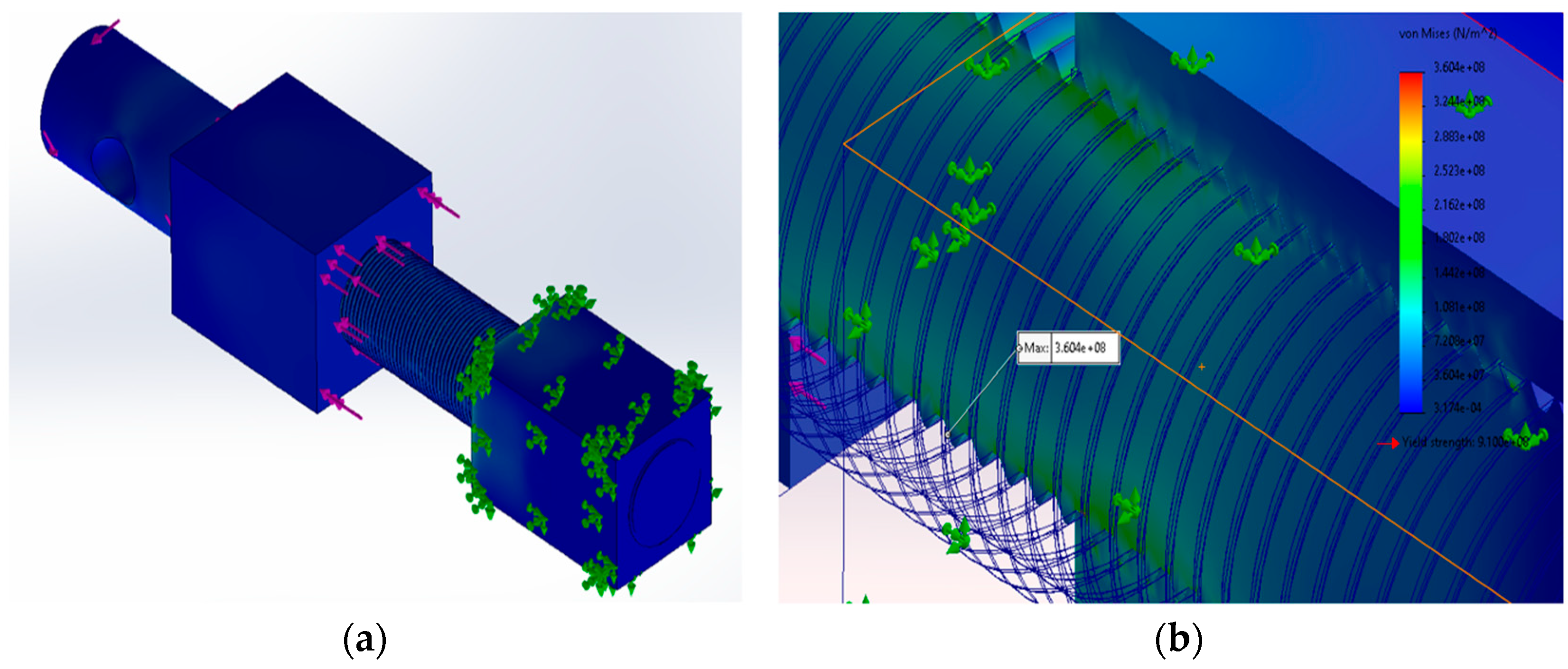
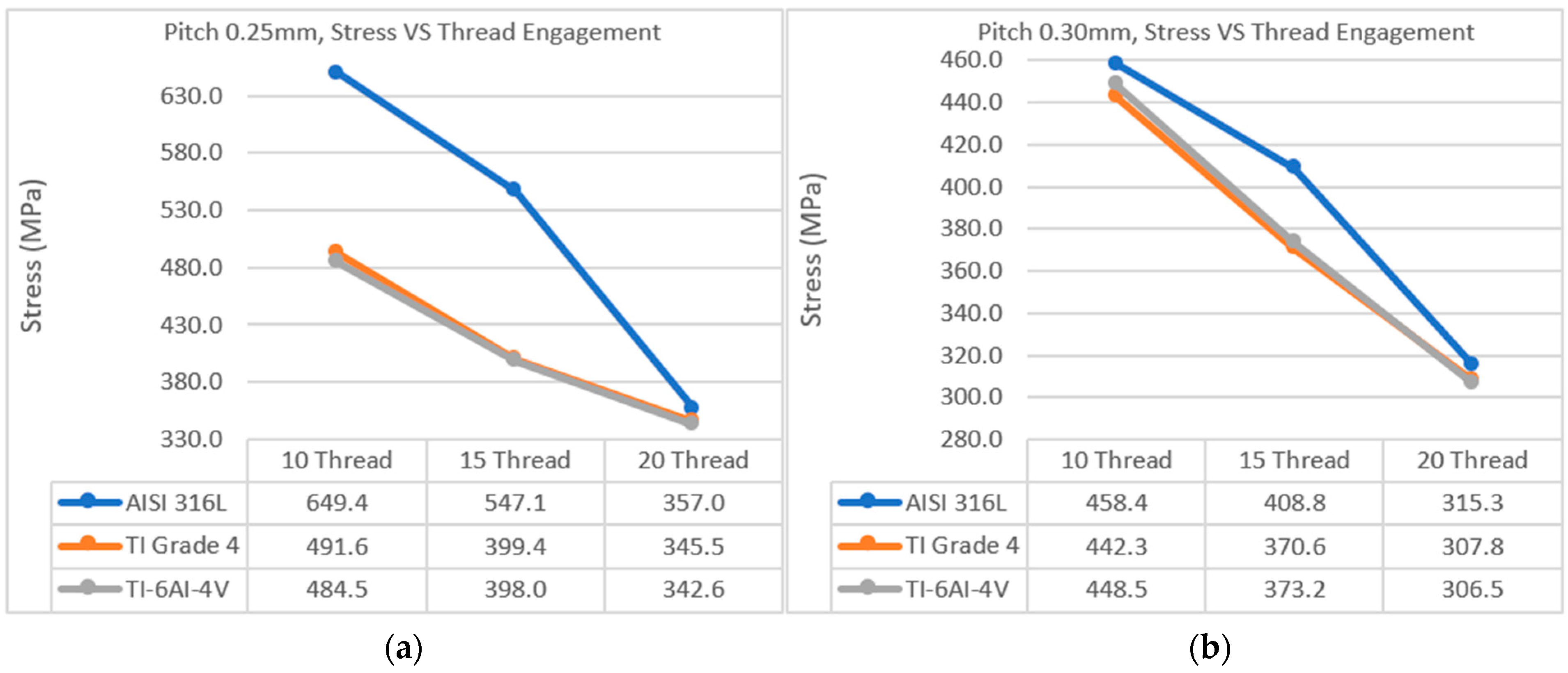
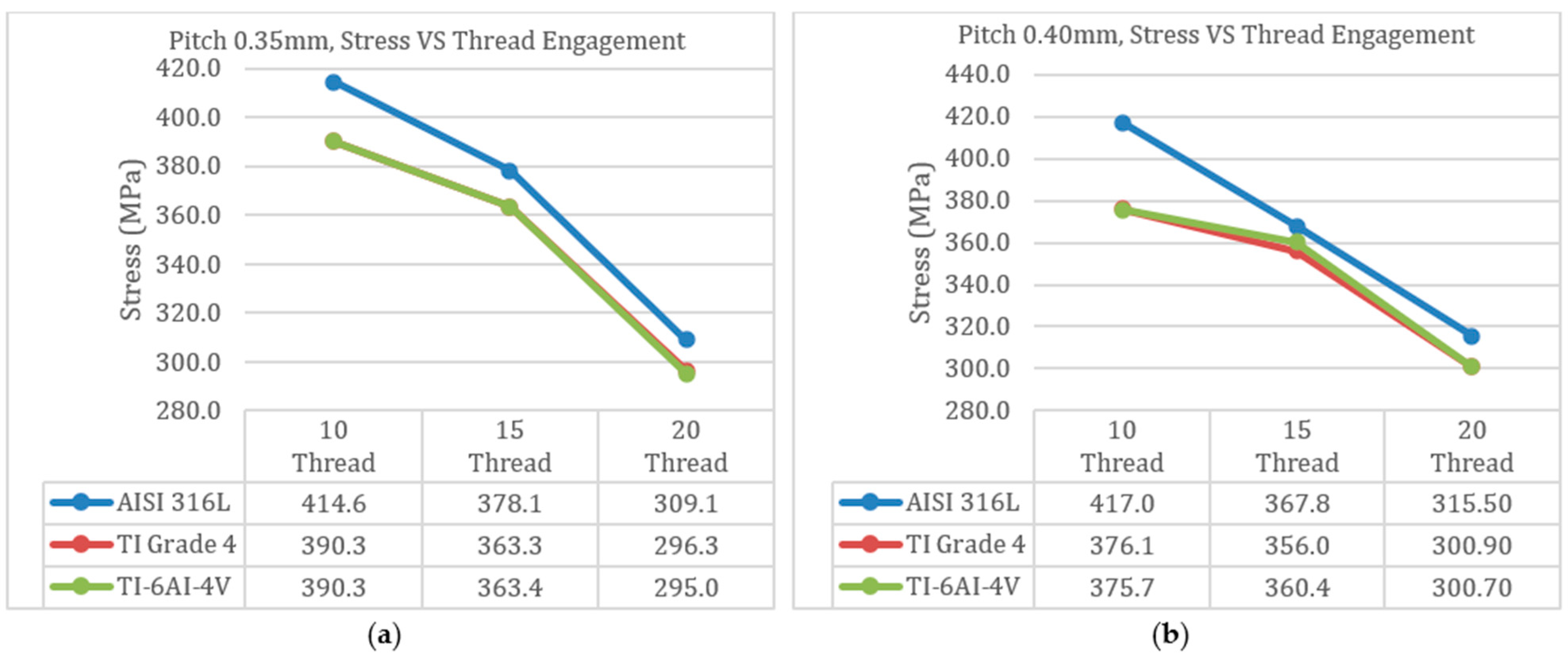
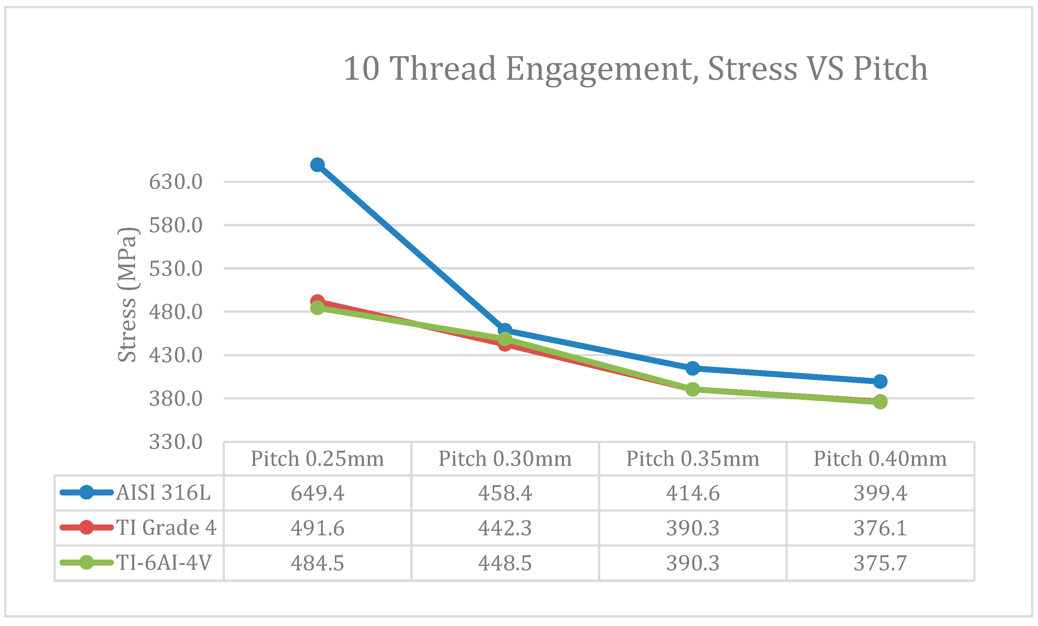
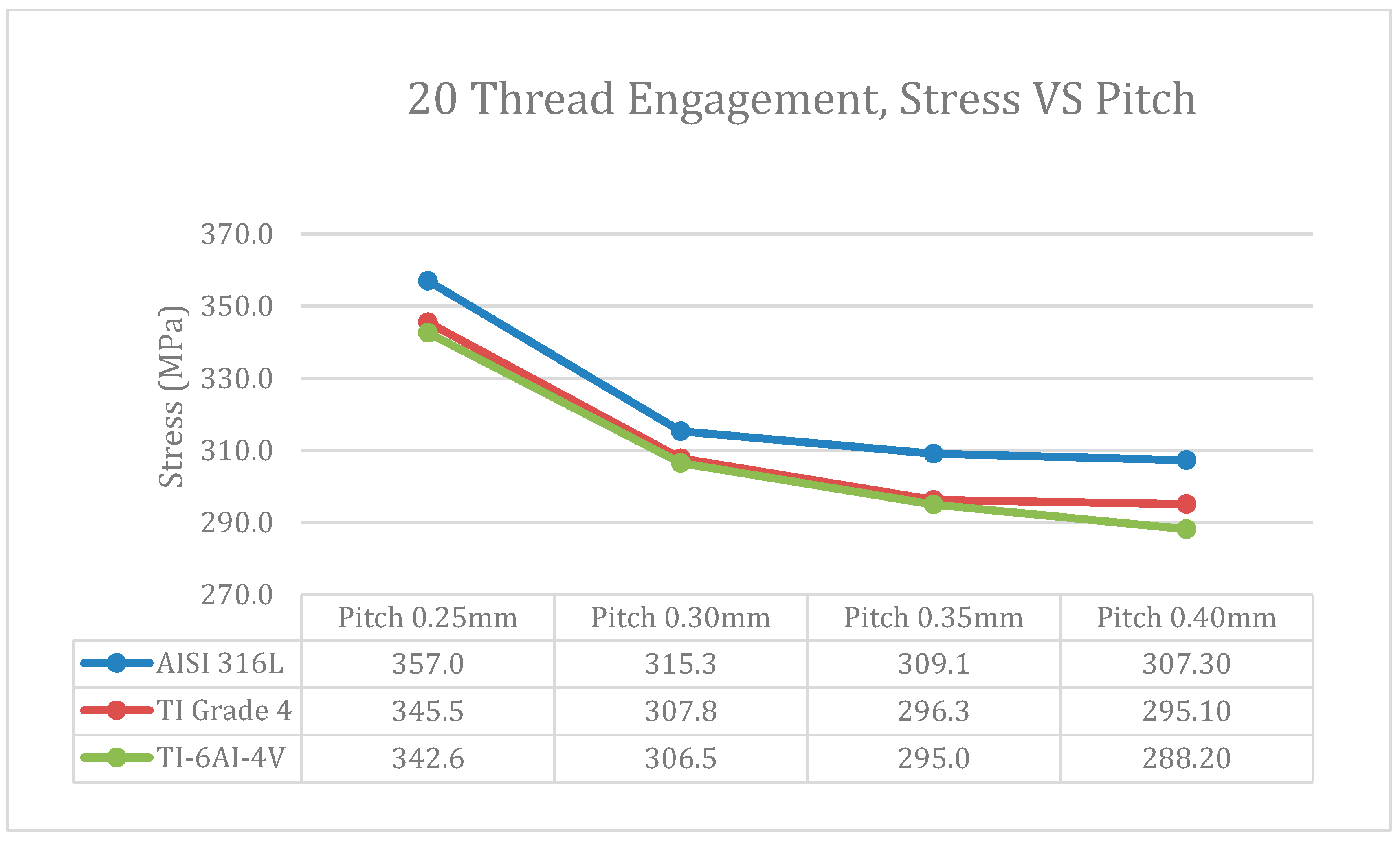
3.1. Stress Results

The stress simulation condition diagram, shown in Figure 6, offers a comprehensive overview of the outcomes obtained from rigorous testing on the designated rig. This diagram serves as a critical tool in assessing the structural integrity and performance of the system under varying stress conditions.
Table 5 illustrates the stress simulation results while Table 6, Table 7 and Table 8 offer a detailed breakdown of the SolidWorks simulation sample sizes, organized by pitch size, followed by thread size and material choice. A total of 36 simulations were meticulously conducted, providing a broad range of insights into the simulation behavior under stress and torque. Among the pitch variations tested (0.25 mm, 0.30 mm, 0.35 mm, and 0.40 mm), maximum von Mises stress exceeded the upper limit of the yield strength (310 MPa) for annealed Stainless Steel Austenitic AISI 316L, indicating that deformation and failure are likely during consolidation. The simulation results indicated that maximum stress for Titanium Commercial Purity Grade 4 (annealed) with a pitch of 0.25 mm indicates a potential risk, falling within the limits of its yield strengths. Under the given consolidation conditions, this titanium alloy may experience deformation, highlighting a risky scenario for deformation. Conversely, for Titanium Alpha-Beta Alloy Ti-6Al-4V (annealed), maximum von Mises stress for all pitches remained below the lower limit of its material yield strengths, indicating a favorable scenario and suggesting it is less susceptible to deformation under the given consolidation conditions. These findings underscore the significant influence of pitch size on the mechanical behavior of materials during the consolidation process.
Figure 7 and Figure 8 depict the graphical representations of stress on the thread corresponding to different pitches: 0.25 mm, 0.30 mm, 0.35 mm, and 0.40 mm, respectively. These figures visually demonstrate how stress levels vary along the thread under various pitch conditions, offering insight into the material’s performance and behavior in response to pitch size and engagement threads. Analyzing these graphs provides valuable information about stress distribution along the thread, aiding in the identification of potential failure points or areas requiring reinforcement. This visual representation serves as a powerful tool for understanding the impact of pitch variation on material mechanical characteristics, facilitating informed decision making in design and optimization. Figure 7a indicates that Stainless Steel Austenitic AISI 316L (annealed), specifically with 10 and 15 engagement thread faces, experiences significantly higher stress levels compared to Titanium alloy counterparts. Additionally, stress on Stainless Steel Austenitic AISI 316L (annealed) material exceeds the upper limit of 310 MPa for all thread engagements, possibly due to the 0.25 mm pitch being too fine to withstand the applied load of 1200 N and 1 N.m torque. Concerning Titanium Commercial Purity Grade 4 (annealed) with 10-thread engagement, there is a potential risk of deformation as stress falls within the material’s yield strength range. However, physical testing is necessary to confirm this risk conclusively. In Figure 7b, stress outcomes for a 0.30 mm pitch indicate that stainless steel austenitic AISI 316L (annealed), particularly with 10-, 15-, and 20-thread engagements, exceed the upper limit of the material yield strength, suggesting susceptibility to plastic deformation under these conditions. Nonetheless, all other simulated results can withstand the conditions.
In Figure 8a, the results for both titanium alloys exhibit a similar result. The trend line for titanium alpha beta alloy Ti-6Al-4V (annealed) essentially overlays that of titanium commercial purity grade 4 (annealed), giving the appearance of only two distinct trends in Figure 8a. Furthermore, the trend line for these three materials is very consistent, but stainless steel austenitic AISI 316L (annealed) have surpassed the upper limit of the material yield strength. In Figure 8b, it is evident that the stress experienced by Annealed Steel Austenitic AISI 316L exceeds its material’s yield strength. Conversely, the stress in the titanium alloy remains below its material’s yield strength.
Based on simulations, the finite element analysis (FEA) simulations could consistently highlight the threaded area as the critical point of contact. Maximum stress is consistently localized within this threaded region across all scenarios, underscoring its significance as a focal point for stress concentration. As evident from Table 7 and the trend lines in Figure 7 and Figure 8 illustrating the relationship between tensile stress and thread engagement, a consistent pattern emerges where increased thread engagement correlates with lower stress levels. This trend is attributed to the effective dispersion of stress across a larger area with higher thread engagement, consequently reducing stress concentration in specific regions and lowering the risk of failure. Additionally, the stress pattern observed in the tread of the annealed Stainless Steel Austenitic AISI 316L is particularly noteworthy. In all simulated specimens, the maximum stress in the annealed Stainless Steel Austenitic AISI 316L surpasses its material’s yield strength. This finding suggests that the material may not meet the required conditions for the motorized intramedullary leg-lengthening nail.
Table 6. Material properties.
MaterialsYield Strength (MPa)
Stainless steel austenitic AISI 316L (annealed)170–310
Titanium commercial purity Grade 4 (annealed)483–655
Titanium alpha beta alloy Ti-6Al-4V (annealed)786–910
In Figure 9, Figure 10 and Figure 11, a clear trend emerges where finer pitch threads experience higher stress levels. The finer pitch leads to a decrease in the contact area of the thread, resulting in a smaller area for load concentration, consequently elevating stress within the thread. Stress concentration significantly impacts the reliability and safety of threaded connections, especially when loads are applied to segments with finer contact areas. These concentrated stress points are prone to material deformation, yielding, and in extreme cases, failure. In Figure 9 and Figure 10, the AISI 316L with a pitch of 0.25 mm shows a noticeably higher von Mises stress. This phenomenon is attributed to the reduced contact area resulting from the smaller pitch size and limited thread engagement. Conversely, larger pitch threads offer a key advantage in the form of a broader contact area, facilitating a more even distribution of applied loads across the threads. This broader contact area reduces stress concentrations in the threaded connection, enhancing its robustness and reducing susceptibility to failure due to extreme stress concentrations. A comprehensive understanding of stress concentrations in threaded connections is crucial for safeguarding the overall integrity and durability of the joint, aligning with strategies aimed at improving its reliability under diverse loading conditions.

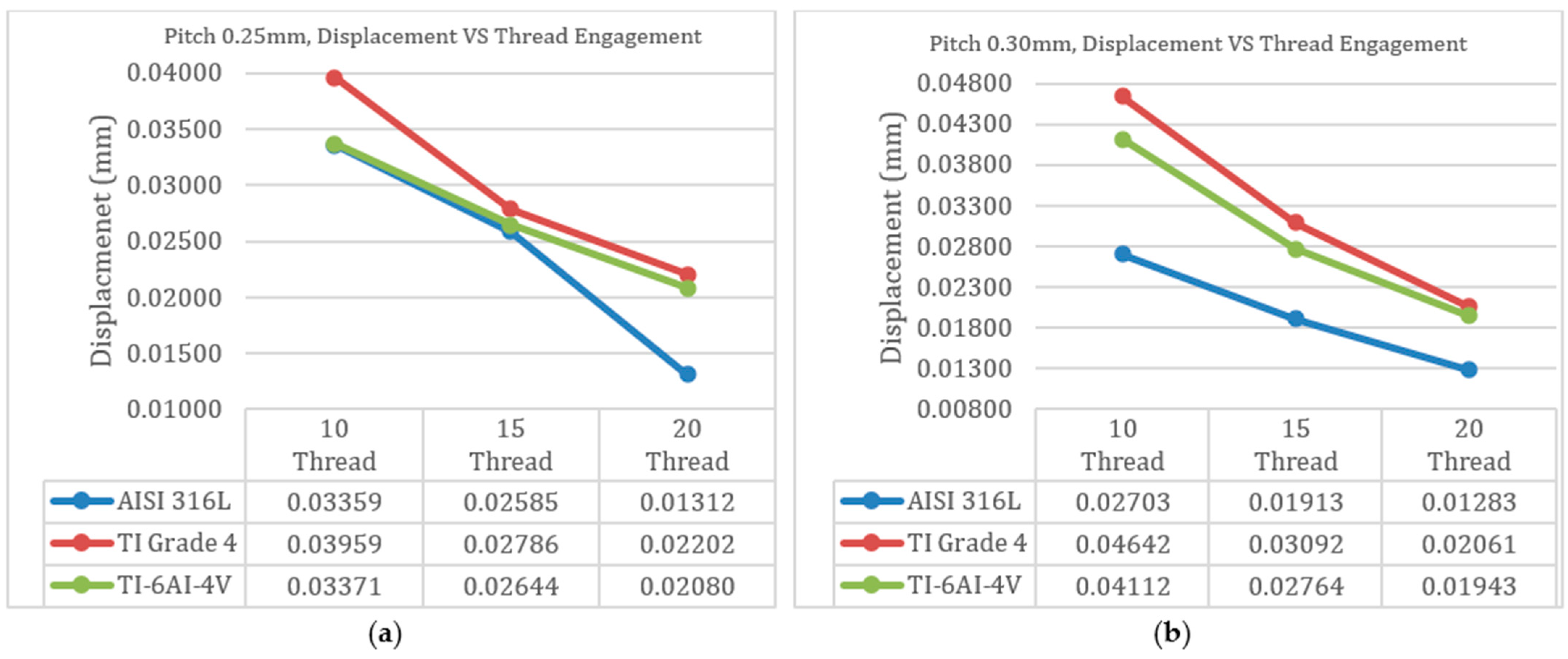
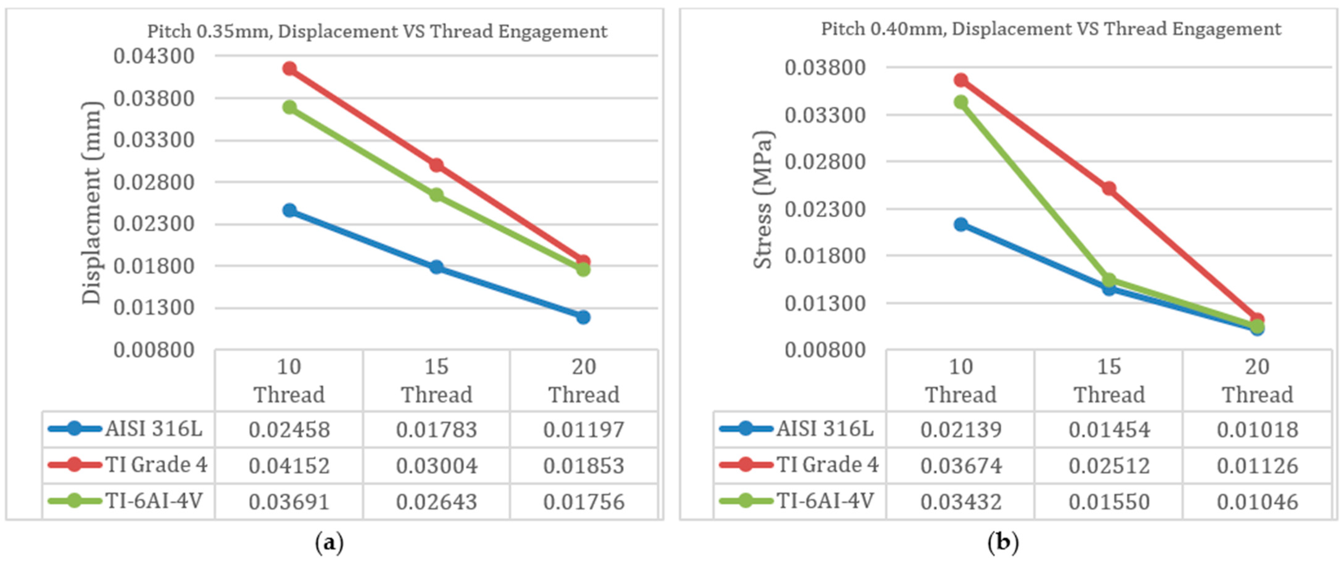
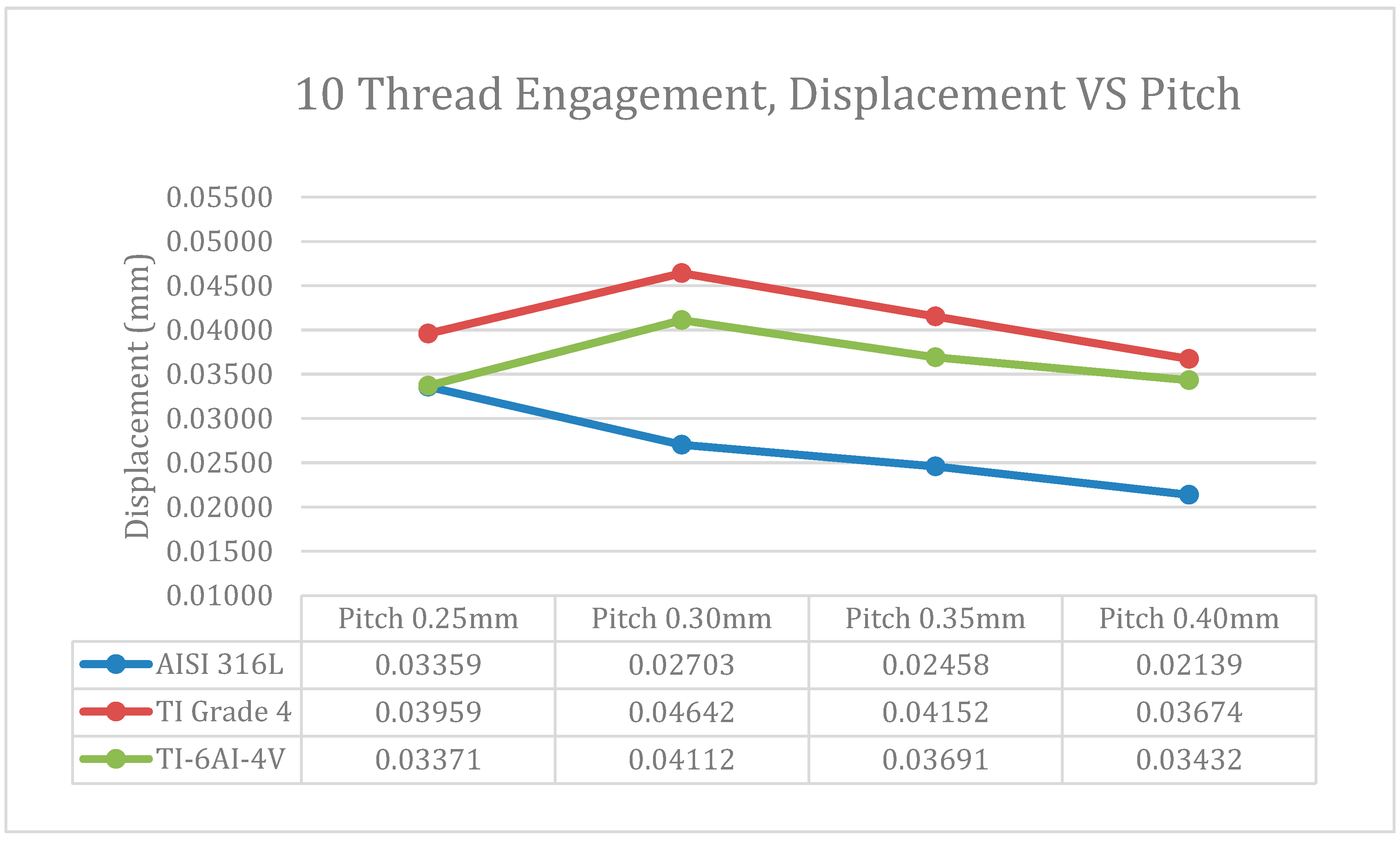
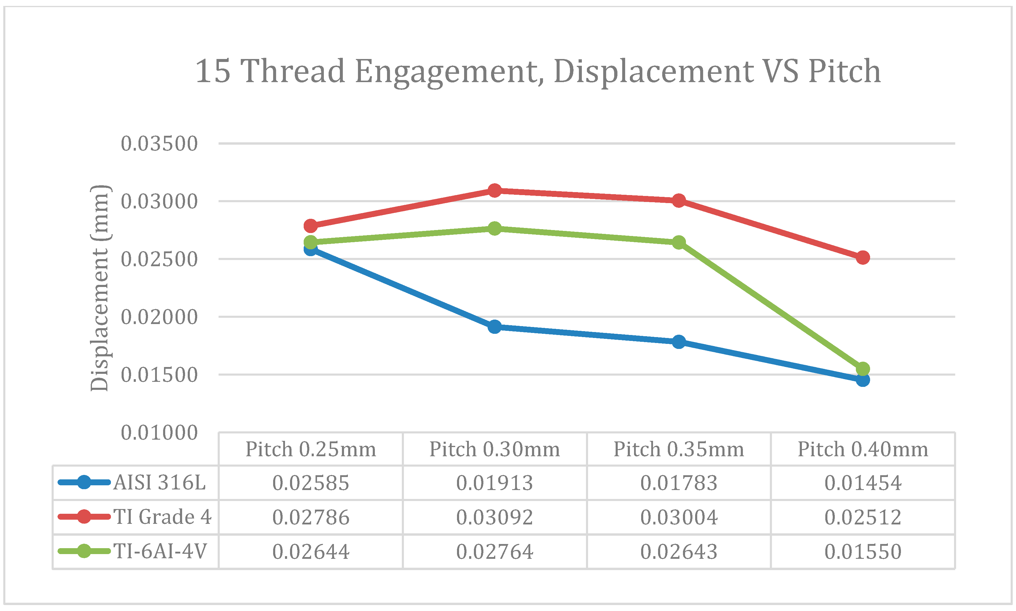
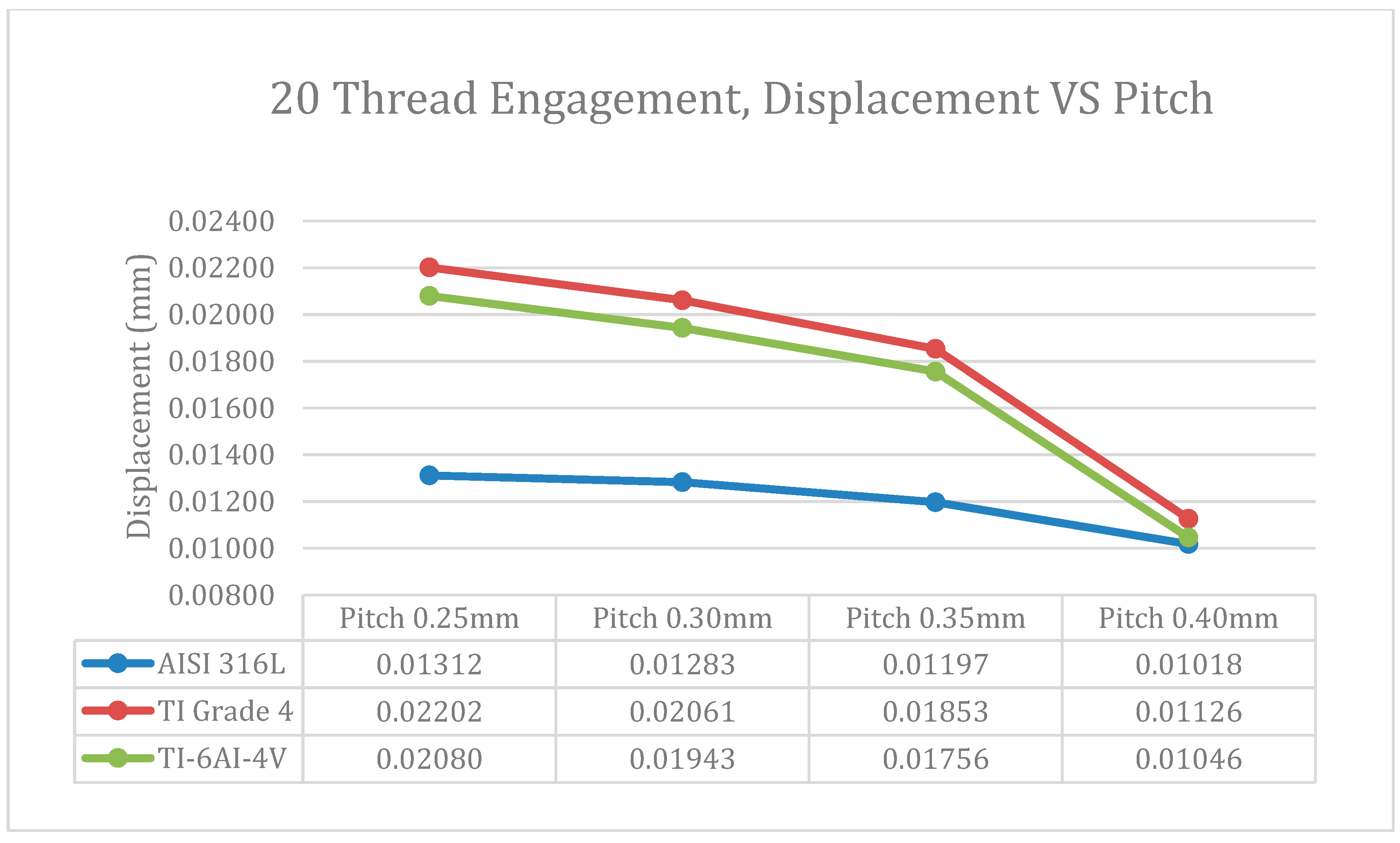
3.2. Displacement Results

In Figure 12, the most significant displacement is marked in red. This displacement is excluded from consideration because this section of the load holder serves as a platform for the human loading of 1200 N. The red-highlighted corner is positioned farthest from the center of the rod. As the rod rotates under torque, frictional contact with the load holder causes it to move. Consequently, the corners experience the greatest displacement.
Table 7 reveals a notable trend in the total displacement values (rounded off to 3 s.f.), showcasing that Titanium Commercial Purity Grade 4 (annealed) exhibits the highest displacement among all pitches and engagement threads. Following closely is the Stainless Steel Austenitic AISI 316L (annealed), which exhibits the least total displacement. This observation highlights the distinct mechanical behaviors of these materials under the given conditions, with Titanium Commercial Purity Grade 4 showcasing the most significant displacement, Titanium Alpha-Beta Alloy Ti-6Al-4V displaying an intermediate response, and Stainless Steel Austenitic AISI 316L demonstrating the least total displacement. Understanding these displacement patterns is crucial for optimizing the selection of materials based on specific project requirements, ensuring structural stability and performance in various applications.
Table 7. Displacement simulation results.
Total Displacement (mm)
PitchSimulation10 Thread15 Thread20 Thread
Stainless steel austenitic AISI 316L (annealed)0.03360.02590.0131
0.25 mmTitanium commercial purity Grade 4 (annealed)0.03950.02780.0220
Titanium alpha beta alloy Ti-6Al-4V (annealed)0.03370.02640.0208
Stainless steel austenitic AISI 316L (annealed)0.02700.01910.0128
0.30 mmTitanium commercial purity Grade 4 (annealed)0.04640.03090.0206
Titanium alpha beta alloy Ti-6Al-4V (annealed)0.04110.02760.0194
Stainless steel austenitic AISI 316L (annealed)0.02460.01780.119
0.35 mmTitanium commercial purity Grade 4 (annealed)0.04150.03000.0185
Titanium alpha beta alloy Ti-6Al-4V (annealed)0.03690.02640.0175
Stainless steel austenitic AISI 316L (annealed)0.02130.01450.0101
0.40 mmTitanium commercial purity Grade 4 (annealed)0.03670.02510.0112
Titanium alpha beta alloy Ti-6Al-4V (annealed)0.03430.01550.0104
For Figure 13 and Figure 14, data analysis reveals that Titanium Commercial Purity Grade 4 (annealed) demonstrates the highest displacement among the three types of engagement threads. The impact of material strength becomes notably significant, with Titanium Commercial Purity Grade 4 (annealed) displaying the most substantial displacement under a torque load of 1.1 N·m. This highlights the pivotal role of material strength in determining the response to applied torque, showcasing both the robustness and susceptibility to deformation of Titanium Commercial Purity Grade 4 (annealed) under the specified torque conditions, despite exhibiting the best results. However, considering the risk of stress exceeding the lower limit, it may not be the optimal material choice in this scenario. Additionally, the data illustrate a clear trend where displacement decreases with an increase in thread engagement. This trend is attributed to the reduced contact area and friction due to torque with lower thread engagement, while higher thread engagement leads to an expanded contact area, increasing frictional force, and subsequently reducing displacement.
Figure 15, Figure 16 and Figure 17 visually depict the relationship between displacement and pitch across various thread engagements. According to the findings outlined in Table 8, Stainless Steel Austenitic AISI 316L (annealed), boasting the highest elastic modulus of 205,000 MPa, showcases the least displacement. Conversely, Titanium Commercial Purity Grade 4 (annealed), with the lowest elastic modulus, exhibits the highest displacement. This emphasizes the significant impact of material properties, particularly elastic modulus, on the observed displacement trends concerning pitch and thread engagement. Ultimately, it has been demonstrated that a torque of 1.1 N·m is sufficient for rotating the motorized intramedullary lengthening nail across all pitch sizes.
Table 8. Material properties of elastic modulus.
MaterialsElastic Modulus (MPa)
Stainless steel austenitic AISI 316L(annealed)205,000
Titanium commercial purity Grade 4 (annealed)112,000
Titanium alpha beta alloy Ti-6Al-4V (annealed)119,000

4. Recommendation

The recommendations provided in this section derive from a comprehensive structural analysis conducted on the motorized leg-lengthening device. The report emphasizes the examination of threads, scrutiny of stress concentrations, and evaluation of overall performance as key priorities [12,13,14]. These recommendations aim to address identified areas of concern, strengthen the device, and optimize the structural performance of threads during the leg-lengthening procedure. Implementing these recommendations is crucial for advancing the safety and effectiveness of medical devices dedicated to limb lengthening procedures. The stress analysis yielded critical insights for each pitch size (0.25 mm, 0.30 mm, 0.35 mm, 0.40 mm) and respective materials. In the case of Stainless Steel Austenitic AISI 316L (annealed), the maximum stress exceeded its yield strength, indicating a significant risk of deformation and failure during consolidation. Conversely, Titanium Commercial Purity Grade 4 (annealed) showed stress levels within its yield strengths, suggesting susceptibility to deformation under the specified torque conditions. In contrast, Titanium Alpha-Beta Alloy Ti-6Al-4V (annealed) demonstrated stress levels below its lower yield limit, suggesting a more favorable scenario for resistance against deformation. These findings underscore the importance of material selection in mitigating the risk of structural issues during limb lengthening device consolidation, highlighting the potential advantages of Titanium Alpha-Beta Alloy Ti-6Al-4V (annealed) for enhanced deformation resistance. The displacement analysis revealed distinct behaviors among the materials and thread configurations. Stainless Steel Austenitic AISI 316L (annealed) consistently exhibited the least displacement, indicating superior stability under the specified conditions. Conversely, Titanium Commercial Purity Grade 4 (annealed) consistently displayed the highest displacement, suggesting its tendency to rotate the thread. Additionally, the 20-engagement thread configuration demonstrated the most consistent displacement across all pitch sizes, suggesting its efficacy in maintaining stability and indicating its potential suitability for limb lengthening device designs across various applications. These findings offer valuable insights for optimizing device performance and ensuring structural reliability in limb lengthening applications. Table 9 outlines the recommended configurations for each pitch size, with Titanium Alpha-Beta Alloy Ti-6Al-4V (annealed) emerging as the preferred material choice due to its lower stress levels and displacement, indicating enhanced resistance to deformation under the specified torque conditions. Furthermore, the 20-thread engagement configuration is universally recommended for all pitch sizes (0.25 mm, 0.30 mm, 0.35 mm, 0.40 mm) due to its consistent displacement performance, suggesting its suitability for limb-lengthening device designs across a range of applications. These recommendations provide valuable guidance for optimizing limb lengthening devices, emphasizing material and thread selection to enhance performance and reliability.
Ensuring the safety and reliability of limb-lengthening procedures requires a comprehensive approach. Material selection is paramount, with preference given to high-strength and deformation-resistant materials like Titanium Alpha-Beta Alloy Ti-6Al-4V (annealed), which enhances the device’s ability to withstand applied stresses. The study recommends a 20-thread engagement configuration, providing consistent displacement across various pitch sizes, thus improving reliability and reducing the risk of deformation. Regular monitoring and maintenance practices are essential to promptly detect the signs of wear or stress. Adhering to material yield strength limits, especially for Stainless Steel Austenitic AISI 316L (annealed) and Titanium Commercial Purity Grade 4 (annealed), is critical to prevent deformation and failure.
Continued research and development efforts in machine learning [16,17,18,19,20,21,22] and artificial intelligence [23,24,25,26,27,28,29,30,31] can drive innovation, exploring advanced materials and design configurations to further enhance safety and reliability. Standardization and guidelines, along with comprehensive training for medical professionals, ensure consistent best practices. Patient-specific designs, accommodating individual anatomical variations, contribute to the overall safety and effectiveness of limb lengthening procedures. Integrating these measures enables limb lengthening procedures to be conducted with a heightened focus on safety and reliability, ultimately improving patient outcomes and minimizing complications. Moreover, fabricating a physical test rig for comprehensive testing is recommended. This step validates and confirms the accuracy of simulation results. A physical test rig allows for real-world experimentation, providing tangible evidence to verify the reliability and effectiveness of simulated outcomes. This hands-on testing approach instills an extra layer of confidence in the performance and structural integrity of the motorized leg-lengthening device, ensuring that it meets expected standards and safety requirements.

5. Conclusions

A comprehensive analysis of stress and displacement behaviors in limb lengthening device components has been undertaken, focusing particularly on pitch sizes and material compositions. The findings from extensive SolidWorks simulations offer valuable insights, leading to strategic recommendations aimed at optimizing device performance and ensuring the reliability of threads. Material selection plays a crucial role in determining stress and displacement outcomes. Stainless Steel Austenitic AISI 316L (annealed) exhibited potential deformation risks, with stress surpassing its yield strength. Titanium Commercial Purity Grade 4 (annealed) showed susceptibility to deformation, while Titanium Alpha-Beta Alloy Ti-6Al-4V (annealed) emerged as a promising option, displaying lower stress levels and enhanced resistance to deformation. Moreover, the 20-thread engagement configuration consistently demonstrated the most stable displacement across various pitch sizes, indicating reliability and potential suitability for limb-lengthening device designs. The study suggests Titanium Alpha-Beta Alloy Ti-6Al-4V (annealed) as the preferred material due to its favorable stress and displacement characteristics, highlighting enhanced resistance to deformation. The universally recommended 20-thread engagement configuration offers stable displacement performance across diverse pitch sizes, although it is acknowledged that the associated cost may be considerably higher. To validate and confirm the reliability and accuracy of SolidWorks simulations, future research could incorporate physical testing, providing an additional layer of assurance regarding device safety and performance. Furthermore, research should focus on exploring innovative design configurations to optimize stress distribution and minimize deformation risks, ultimately leading to more robust and reliable limb-lengthening devices [32,33,34,35]. This dual focus on experimental validation and advanced design exploration has the potential to significantly contribute to continual improvements in safety and efficacy in limb lengthening procedures. The study’s findings have significant implications for these procedures, prioritizing material strength and appropriate thread configurations to enhance device safety and reliability. In conclusion, this study offers a thorough analysis of stress and displacement behaviors in limb-lengthening device components, providing practical recommendations for material selection and optimal thread configurations. These insights contribute to ongoing efforts to improve the safety and reliability of limb lengthening procedures. The proposed enhancements in materials, thread design, and testing methodologies aim to advance the overall design and performance of motorized intramedullary leg-lengthening devices. These improvements are poised to enhance the safety and efficacy of medical devices used in limb-lengthening procedures, ultimately benefiting patients by minimizing complications and optimizing outcomes. The project will progress to the manufacturing phase, where the test rig will undergo tensile loading with torque. This practical phase, following the initial Finite Element Analysis (FEA) simulation stages, offers a real-world assessment of the designed limb lengthening device. Tensile loading with torque serves as a critical evaluation, providing insights into the device’s structural integrity, durability, and performance under the conditions simulating those encountered during limb lengthening procedures. This hands-on approach will significantly contribute to understanding the device’s mechanical behavior and inform potential refinements for improved safety and reliability in limb lengthening procedures. To provide a detailed illustration and description of the devices used in the patients for the motorized intramedullary lengthening nail, I have summarized the following explanation below.
  • Intramedullary mail (Figure 1a)
    • Design and structure: The intramedullary nail is a long, slender rod that is inserted into the medullary cavity of the bone. It is designed to provide structural support during the bone lengthening process.
    • Material: Typically made from biocompatible materials such as titanium or stainless steel to ensure durability and minimize adverse reactions within the human body.
  • Dismantled Parts (Figure 1b)
    • The intramedullary nail can be dismantled into individual parts for detailed examination and analysis. These parts include the main rod, the motorized extension mechanism, and the screw threads.
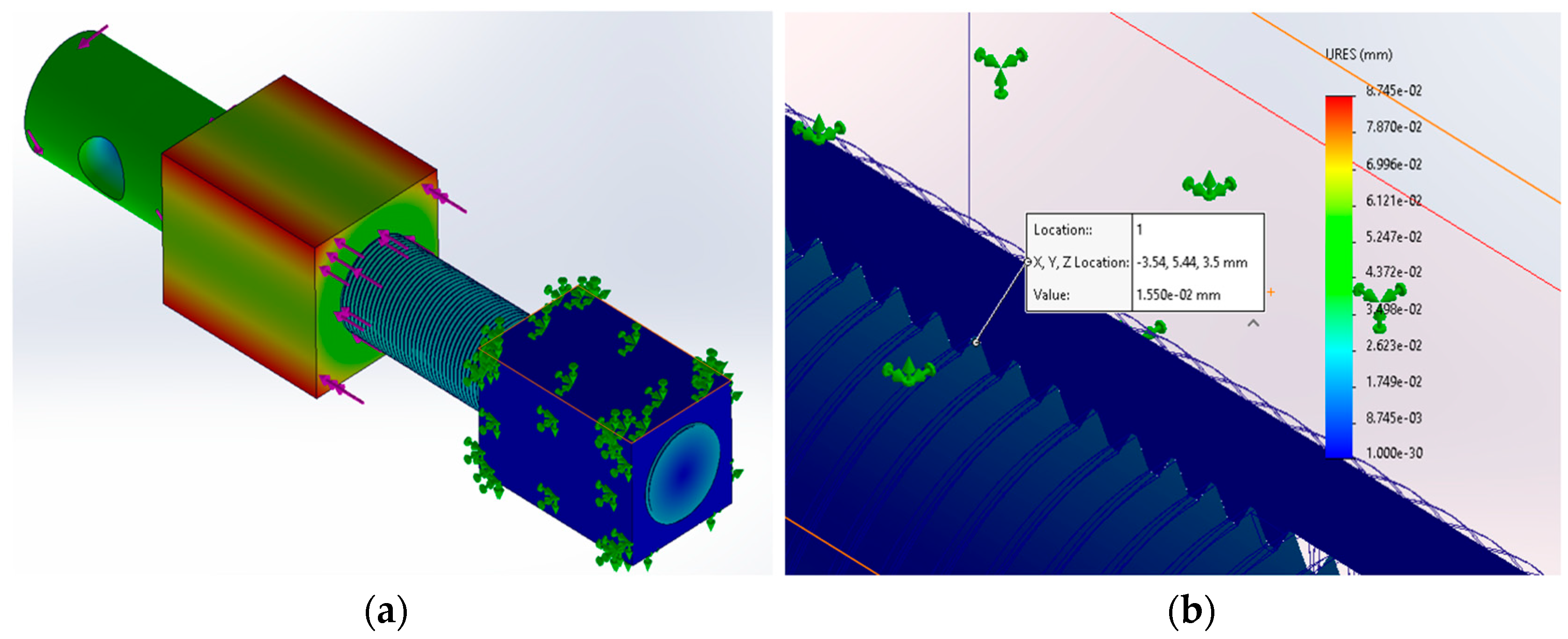
  • Three-Dimensional Engineering Drawing (Figure 2)
    • Detailed examination: A 3D engineering drawing of the intramedullary nail, created using SolidWorks software, provides a comprehensive view of its design and dimensions. This drawing captures the thread geometry, pitch, depth, and interaction with the overall structure.
    • Stress points identification: The 3D representation helps identify potential weak points and areas of stress concentration, crucial for predicting failures and improving the design.
  • Improvised Rig for Simulation (Figure 3)
    • Simulation testing: An improvised rig is used to simulate real-world conditions and perform practical testing on the intramedullary nail. This rig allows for the application of stress, strain, and torque, facilitating a thorough evaluation of the nail’s performance under various conditions.
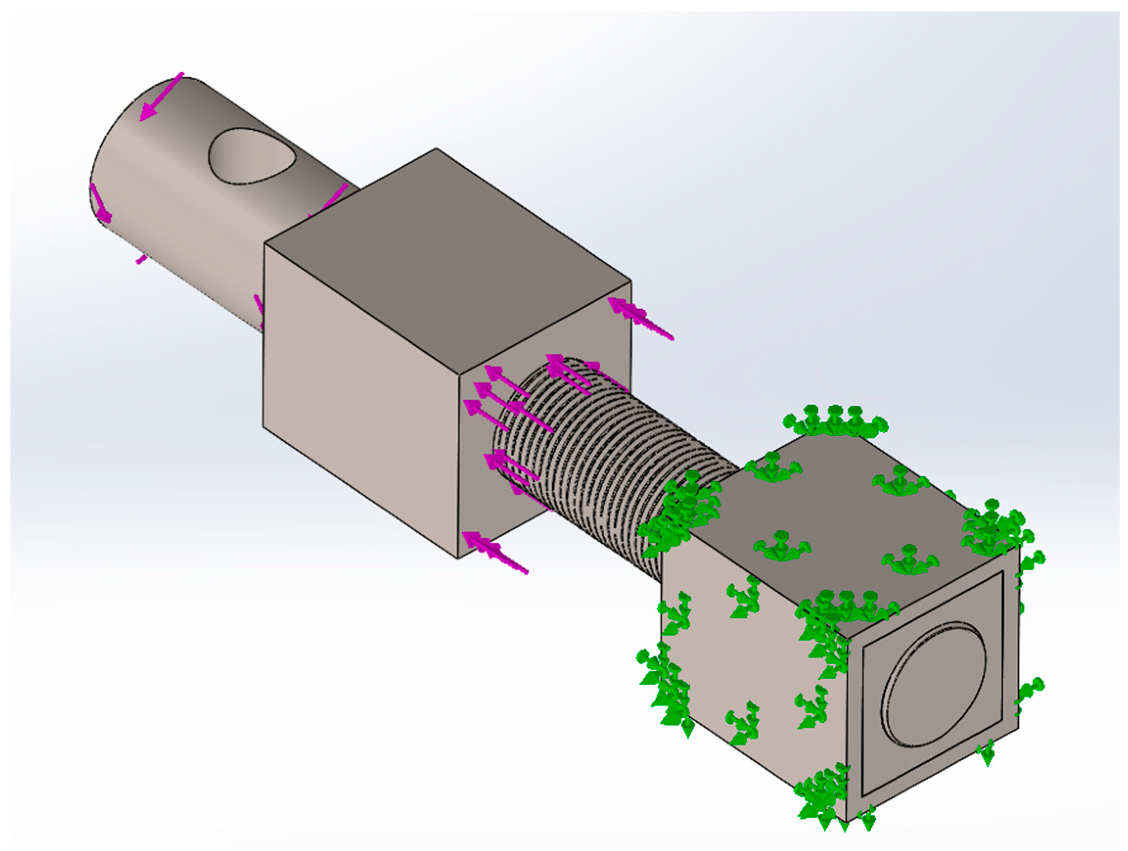
  • Fixed Support Geometry (Figure 4)
    • Simulation testing: An improvised rig is used to simulate real-world conditions and perform practical testing on the intramedullary nail. This rig allows for the application of stress, strain, and torque, facilitating a thorough evaluation of the nail’s performance under various conditions.
  • Thread Loading (Figure 5)
    • Illustrates the thread loading with a total force of 1200 N. This illustration is used to understand how the device handles tensile loading with torque, which is vital for ensuring the structural integrity of the threads during the consolidation phase.
  • Torque Loading (Figure 6)
    • Shows the torque loading applied during the simulations, set at 1.1 N·m across all simulations. This consistent torque input is crucial for the fair comparisons of various parameters and conditions being examined.

Author Contributions

Conceptualization, Methodology, Investigation, Supervision, Resources and Software, C.L.K.; Methodology, Investigation and Data Curation, C.K.H.; Project administration, Resources, Supervision, Visualization and Formal Analysis, H.W.N.; Methodology, Visualization and Formal Analysis, Y.Y.K.; Investigation, Supervision, Data Curation and Funding Acquisition, T.H.T. All authors have read and agreed to the published version of the manuscript.

Funding

This research received no external funding.

Data Availability Statement

The data presented in this study are available in this article.

Conflicts of Interest

The authors declare no conflicts of interest.

References

  1. Robert Rozbruch, S.; Birch, J.G.; Dahl, M.T.; Herzenberg, J.E. Motorized Intramedullary Nail for Management of Limb-length Discrepancy and Deformity. J. Am. Acad. Orthop. Surg. 2014, 22, 403–409. [Google Scholar] [CrossRef] [PubMed]
  2. Robert Rozbruch, S. Limb Lengthening—An Overview; HHS: Washington, DC, USA, 2020.
  3. Bloudoff-Indelicato, M. A History of Limb Lengthening [Timeline]. Scintific American, 27 December 2012. [Google Scholar]
  4. Barker, J. Limb-Lengthening Surgery: A Look at the Pros and Cons; Boston Children’s Hospital: Boston, MA, USA, 2021. [Google Scholar]
  5. Hlukha, L.P.; Alrabai, H.M.; Sax, O.C.; Hammouda, A.I.; McClure, P.K.; Herzenberg, J.E. Mechanical Failures in Magnetic Intramedullary Lengthening Nails. J. Bone Jt. Surg. Am. 2023, 105, 113–127. [Google Scholar] [CrossRef] [PubMed]
  6. Sinai Hospital of Baltimore. International Center for Limb Lengthening. Rubin Institute for Advanced Orthopedics. 2019. Available online: https://www.limblength.org/ (accessed on 26 June 2024).
  7. Alana Biggers, M.M. What’s the Average Weight for Men? Rubin Institute for Advanced Orthopedics: Baltimore, MD, USA, 2023. [Google Scholar]
  8. Edwards, C. Materials Used in Medical Implants: How Is the Industry Breaking the Mould? Medical Device Network: New York, NY, USA, 2018. [Google Scholar]
  9. Saini, M.; Singh, Y.; Arora, P.; Arora, V.; Jain, K. Implant biomaterials: A comprehensive review. World J. Clin. Cases 2015, 3, 52–57. [Google Scholar] [CrossRef] [PubMed]
  10. Geetha, M.; Singh, A.K.; Asokamani, R.; Gogia, A.K. Ti based biomaterials, the ultimate choice for orthopaedic implants—A review. Prog. Mater. Sci. 2009, 54, 397–425. [Google Scholar] [CrossRef]
  11. Lutjering, G.; Williams, J.C. Titanium; Springer: Berlin/Heidelberg, Germany, 2007; pp. 21–25. [Google Scholar]
  12. Budynas, R.G.; Nisbett, J.K. Shigley’s Mechanical Engineering Design; McGraw-Hill Science Engineering: New York, NY, USA, 2014. [Google Scholar]
  13. Biomechanics: Principles and Applications; Peterson, D.R.; Bronzino, J.D. (Eds.) CRC Press: Boca Raton, FL, USA, 2002. [Google Scholar]
  14. ISO 13485; Medical Devices—Quality Management Systems—Requirements for Regulatory Purposes. ISO: Geneva, Switzerland, 2016.
  15. Barrett, R.T. Fastener Design Manual. Engineering Library: London, UK, 1990. [Google Scholar]
  16. Kok, C.L.; Fu, X.; Koh, Y.Y.; Teo, T.H. A Novel Portable Solar Powered Wireless Charging Device. Electronics 2024, 13, 403. [Google Scholar] [CrossRef]
  17. LeCun, Y.; Bengio, Y.; Hinton, G. Deep Learning. IEEE Signal Process. Mag. 2015, 13, 199–220. [Google Scholar] [CrossRef] [PubMed]
  18. Goodfellow, I.; Pouget-Abadie, J.; Mirza, M.; Xu, B.; Warde-Farley, D.; Ozair, S.; Courville, A.; Bengio, Y. Generative Adversarial Nets. IEEE Trans. Neural Netw. Learn. Syst. 2018, 29, 1399–1404. [Google Scholar]
  19. Bengio, Y.; Courville, A.; Vincent, P. Representation Learning: A Review and New Perspectives. IEEE Trans. Pattern Anal. Mach. Intell. 2013, 35, 1798–1828. [Google Scholar] [CrossRef] [PubMed]
  20. Silver, D.; Huang, A.; Maddison, C.J.; Guez, A.; Sifre, L.; Van Den Driessche, G.; Schrittwieser, J.; Antonoglou, I.; Panneershelvam, V.; Lanctot, M.; et al. Mastering the Game of Go with Deep Neural Networks and Tree Search. IEEE Trans. Artif. Intell. 2016, 7, 484–488. [Google Scholar] [CrossRef] [PubMed]
  21. Glorot, X.; Bordes, A.; Bengio, Y. Deep Sparse Rectifier Neural Networks. IEEE Trans. Neural Netw. Learn. Syst. 2011, 23, 315–319. [Google Scholar]
  22. Aung, K.H.H.; Kok, C.L.; Koh, Y.Y.; Teo, T.H. An Embedded Machine Learning Fault Detection System for Electric Fan Drive. Electronics 2024, 13, 493. [Google Scholar] [CrossRef]
  23. Chen, J.; Teo, T.H.; Kok, C.L.; Koh, Y.Y. A Novel Single-Word Speech Recognition on Embedded Systems Using a Convolution Neuron Network with Improved Out-of-Distribution Detection. Electronics 2024, 13, 530. [Google Scholar] [CrossRef]
  24. Goldberg, Y. A Primer on Neural Network Models for Natural Language Processing. J. Artif. Intell. Res. 2016, 57, 345–420. [Google Scholar] [CrossRef]
  25. Graves, A.; Mohamed, A.; Hinton, G. Speech Recognition with Deep Recurrent Neural Networks. IEEE Trans. Audio Speech Lang. Process. 2013, 23, 664–675. [Google Scholar]
  26. Dauphin, Y.N.; Fan, A.; Auli, M.; Grangier, D. Language Modeling with Gated Convolutional Networks. IEEE Trans. Comput. Linguist. 2017, 1, 61–71. [Google Scholar]
  27. Mikolov, T.; Chen, K.; Corrado, G.; Dean, J. Efficient Estimation of Word Representations in Vector Space. IEEE Trans. Comput. Linguist. 2013, 9, 1–12. [Google Scholar]
  28. Kok, C.L.; Dai, Y.; Lee, T.K.; Koh, Y.Y.; Teo, T.H.; Chai, J.P. A Novel Low-Cost Capacitance Sensor Solution for Real-Time Bubble Monitoring in Medical Infusion Devices. Electronics 2024, 13, 1111. [Google Scholar] [CrossRef]
  29. Vaswani, A.; Shazeer, N.; Parmar, N.; Uszkoreit, J.; Jones, L.; Gomez, A.N.; Kaiser, Ł.; Polosukhin, I. Attention Is All You Need. IEEE Trans. Neural Netw. Learn. Syst. 2019, 30, 145–157. [Google Scholar]
  30. Goodfellow, I.J.; Shlens, J.; Szegedy, C. Explaining and Harnessing Adversarial Examples. IEEE Trans. Neural Netw. Learn. Syst. 2015, 26, 2692–2704. [Google Scholar]
  31. He, K.; Zhang, X.; Ren, S.; Sun, J. Deep Residual Learning for Image Recognition. IEEE Trans. Comput. Vis. Pattern Recognit. 2016, 60, 770–778. [Google Scholar]
  32. Kok, C.L.; Tan, T.C.; Koh, Y.Y.; Lee, T.K.; Chai, J.P. Design and Testing of an Intramedullary Nail Implant Enhanced with Active Feedback and Wireless Connectivity for Precise Limb Lengthening. Electronics 2024, 13, 1519. [Google Scholar] [CrossRef]
  33. Prendergast, P.J.; Kelly, D.J.; Lee, T.C. Biomechanics and Mechanobiology in Orthopaedic Tissue Engineering: A Review. IEEE Trans. Biomed. Eng. 2008, 55, 1105–1114. [Google Scholar]
  34. Mak, A.F.; Zhang, J.; Boone, W.M. State-of-the-art research in lower-limb prosthetic biomechanics-socket interface: A review. IEEE Trans. Rehabil. Eng. 2003, 11, 361–373. [Google Scholar]
  35. Zhang, S.S.; Zhang, J.Y.; Wang, M.Q. Stress Analysis and Structural Optimization of External Fixator for Limb Lengthening. IEEE Access 2020, 8, 54673–54683. [Google Scholar]
Figure 1. Overall layout of the implant: (a) Intramedullary nail; and (b) Dismantled into induvial parts.
Applsci 14 07296 g001
Figure 2. Overall layout of the 3D engineering drawing: (a) Intramedullary nail; (b) Cross-sectional view.
Applsci 14 07296 g002
Figure 3. Improvise rig for simulation.
Applsci 14 07296 g003
Figure 4. Fix support geometry, thread loading total of 1200 N, torque loading 1.1 N.m.
Applsci 14 07296 g004
Figure 5. Simulation interaction.
Applsci 14 07296 g005
Figure 6. (a) Stress simulation condition; and (b) Stress concentration location.
Applsci 14 07296 g006
Figure 7. Graph for stress vs. thread engagement: (a) pitch 0.25 mm; and (b) pitch 0.30 mm.
Applsci 14 07296 g007
Figure 8. Graph for stress vs. thread engagement: (a) pitch 0.35 mm; and (b) pitch 0.40 mm.
Applsci 14 07296 g008
Figure 9. The 10-thread engagement, stress vs. pitch.
Applsci 14 07296 g009
Figure 10. The 15-thread engagement, stress vs. pitch.
Applsci 14 07296 g010
Figure 11. The 20-thread engagement, stress vs. pitch.
Applsci 14 07296 g011
Figure 12. (a) Displacement simulated diagram; and (b) displacement location.
Applsci 14 07296 g012
Figure 13. Graph for displacement vs. thread engagement: (a) pitch 0.25 mm; and (b) pitch 0.30 mm.
Applsci 14 07296 g013
Figure 14. Graph for displacement vs. thread engagement: (a) pitch 0.35 mm; and (b) pitch 0.40 mm.
Applsci 14 07296 g014
Figure 15. The 10-thread engagement, displacement vs. pitch.
Applsci 14 07296 g015
Figure 16. The 15-thread engagement, displacement vs. pitch.
Applsci 14 07296 g016
Figure 17. The 20-thread engagement, displacement vs. pitch.
Applsci 14 07296 g017
Table 1. Selected materials for simulation.
MaterialsPrices (SGD/kg)Yield Strength (MPa)Elastic Modulus (GPa)Tensile Strength (MPa)Weak Alkalis (pH 9–11)
Stainless steel, austenitic, AISI 316L, annealed4.75–5.48170–310190–205485–560Excellent
Titanium, commercial purity, Grade 4, annealed20.5–22.9483–655107–112241–552Excellent
Titanium, alpha-beta alloy, Ti-6Al-4V, annealed32.2–35.7786–910110–119860–980Excellent
Table 2. Calculated results for torque.
Dimension0.25 mm0.30 mm0.35 mm0.40 mm
Torque1.0055 N m1.0205 N m1.0356 N m1.0507 N m
Table 3. Fiction coefficient for steel and titanium [15].
Bolt/Nut MaterialsLubricantCoefficient of Friction
Steel/BronzeNone added0.15
TitaniumMolybdenum disulfide grease0.10
Table 4. Nodes and elements.
SimulationDegrees of FreedomNodesElementsTime of Simulation
0.25 mm 10 thread
(AISI 316L), (Ti Grade 4), (Ti-6Al-4V)
552,522188,062191,4434 h–5 h
0.25 mm 15 thread
(AISI 316L), (Ti Grade 4), (Ti-6Al-4V)
565,974192,546194,1694 h–5 h
0.25 mm 20 thread
(AISI 316L), (Ti Grade 4), (Ti-6Al-4V)
578,061196,575196,5834 h–5 h
0.30 mm 10 thread
(AISI 316L), (Ti Grade 4), (Ti-6Al-4V)
461,685157,839169,2164 h–5 h
0.30 mm 15 thread
(AISI 316L), (Ti Grade 4), (Ti-6Al-4V)
472,407161,413158,9714 h–5 h
0.30 mm 20 thread
(AISI 316L), (Ti Grade 4), (Ti-6Al-4V)
483,558165,130161,1944 h–5 h
0.35 mm 10 thread
(AISI 316L), (Ti Grade 4), (Ti-6Al-4V)
437,565150,375144,1414 h–5 h
0.35 mm 15 thread
(AISI 316L), (Ti Grade 4), (Ti-6Al-4V)
449,244154,268163,1514 h–5 h
0.35 mm 20 thread
(AISI 316L), (Ti Grade 4), (Ti-6Al-4V)
459,093157,551168,1884 h–5 h
0.40 mm 10 thread
(AISI 316L), (Ti Grade 4), (Ti-6Al-4V)
429,864148,576151,6944 h–5 h
0.40 mm 15 thread
(AISI 316L), (Ti Grade 4), (Ti-6Al-4V)
439,824151,896140,1884 h–5 h
0.40 mm 20 thread
(AISI 316L), (Ti Grade 4), (Ti-6Al-4V)
449,526155,130161,6764 h–5 h
Table 5. Stress simulation results.
Max Von Mises Stress (MPa)
PitchSimulation10 Thread15 Thread20 Thread
Stainless steel austenitic AISI 316L (annealed)649.4547.1357.0
0.25 mmTitanium commercial purity Grade 4 (annealed)491.6399.4345.5
Titanium alpha beta alloy Ti-6Al-4V (annealed)484.5398.0342.6
Stainless steel austenitic AISI 316L (annealed)458.4408.8337.4
0.30 mmTitanium commercial purity Grade 4 (annealed)442.3370.6312.0
Titanium alpha beta alloy Ti-6Al-4V (annealed)448.5373.2307.3
Stainless steel austenitic AISI 316L (annealed)414.6378.1309.1
0.35 mmTitanium commercial purity Grade 4 (annealed)390.3363.3296.3
Titanium alpha beta alloy Ti-6Al-4V (annealed)390.3363.4295.0
Stainless steel austenitic AISI 316L (annealed)423.8367.8339.40
0.40 mmTitanium commercial purity Grade 4 (annealed)408.6356.0334.60
Titanium alpha beta alloy Ti-6Al-4V (annealed)409.7360.4333.50
Table 9. Recommended configuration for each pitch.
PitchEngagement Thread MaterialStress on Thread (MPa)Displacement on Thread (mm)
0.25 mm20 ThreadTitanium alpha beta alloy Ti-6Al-4V (annealed)342.60.0208
0.30 mm20 ThreadTitanium alpha beta alloy Ti-6Al-4V (annealed)306.50.0194
0.35 mm20 ThreadTitanium alpha beta alloy Ti-6Al-4V (annealed)295.00.0176
0.40 mm20 ThreadTitanium alpha beta alloy Ti-6Al-4V (annealed)300.700.0105
Disclaimer/Publisher’s Note: The statements, opinions and data contained in all publications are solely those of the individual author(s) and contributor(s) and not of MDPI and/or the editor(s). MDPI and/or the editor(s) disclaim responsibility for any injury to people or property resulting from any ideas, methods, instructions or products referred to in the content.

