Article

Characterization of Shallow Sedimentary Layers in the Oran Region Using Ambient Vibration Data

by
Ahmed Saadi
1,2,
Juan José Galiana-Merino
2,3,*,
Fethi Semmane
1,
Abdelkrim Yelles-Chaouche
1 and
Abdelouahab Issaadi
1
1
Centre de Recherche en Astronomie, Astrophysique et Géophysique (CRAAG), Algiers 16340, Algeria
2
University Institute of Physics Applied to Sciences and Technologies, University of Alicante, Crta. San Vicente del Raspeig, s/n, 03080 Alicante, Spain
3
Department of Physics, Systems Engineering, and Signal Theory, University of Alicante, Crta. San Vicente del Raspeig, s/n, 03080 Alicante, Spain
*
Author to whom correspondence should be addressed.
Appl. Sci. 2024, 14(16), 7364; https://doi.org/10.3390/app14167364 (registering DOI)
Submission received: 22 July 2024 / Revised: 18 August 2024 / Accepted: 19 August 2024 / Published: 21 August 2024
(This article belongs to the Special Issue Earthquake Engineering: Geological Impacts and Disaster Assessment)

Abstract

:
This study investigates the structure of shear-wave velocities (Vs) in the shallow layers of the Oran region, north-west of Algeria, using non-invasive techniques based on ambient vibration arrays. The region has experienced several moderate earthquakes, including the historical Oran earthquake of 1790. Ambient vibration measurements were carried out at 15 sites throughout the study area. Two methods were used: spatial autocorrelation (SPAC) and frequency–wavenumber analysis (f-k), which allowed us to better constrain Rayleigh wave dispersion curves. The inversion of the dispersion curves derived from the f-k analysis allowed for estimating the shear-wave velocity profiles and the Vs30 value at the sites under study. The other important result of the present study is an empirical equation that has been proposed to predict Vs30 in the Oran region. The determination of near-surface shear-wave velocity profiles is an important step in the assessment of seismic hazard. This study has demonstrated the effectiveness of using ambient vibration array techniques to estimate the soil Vs structure.

1. Introduction

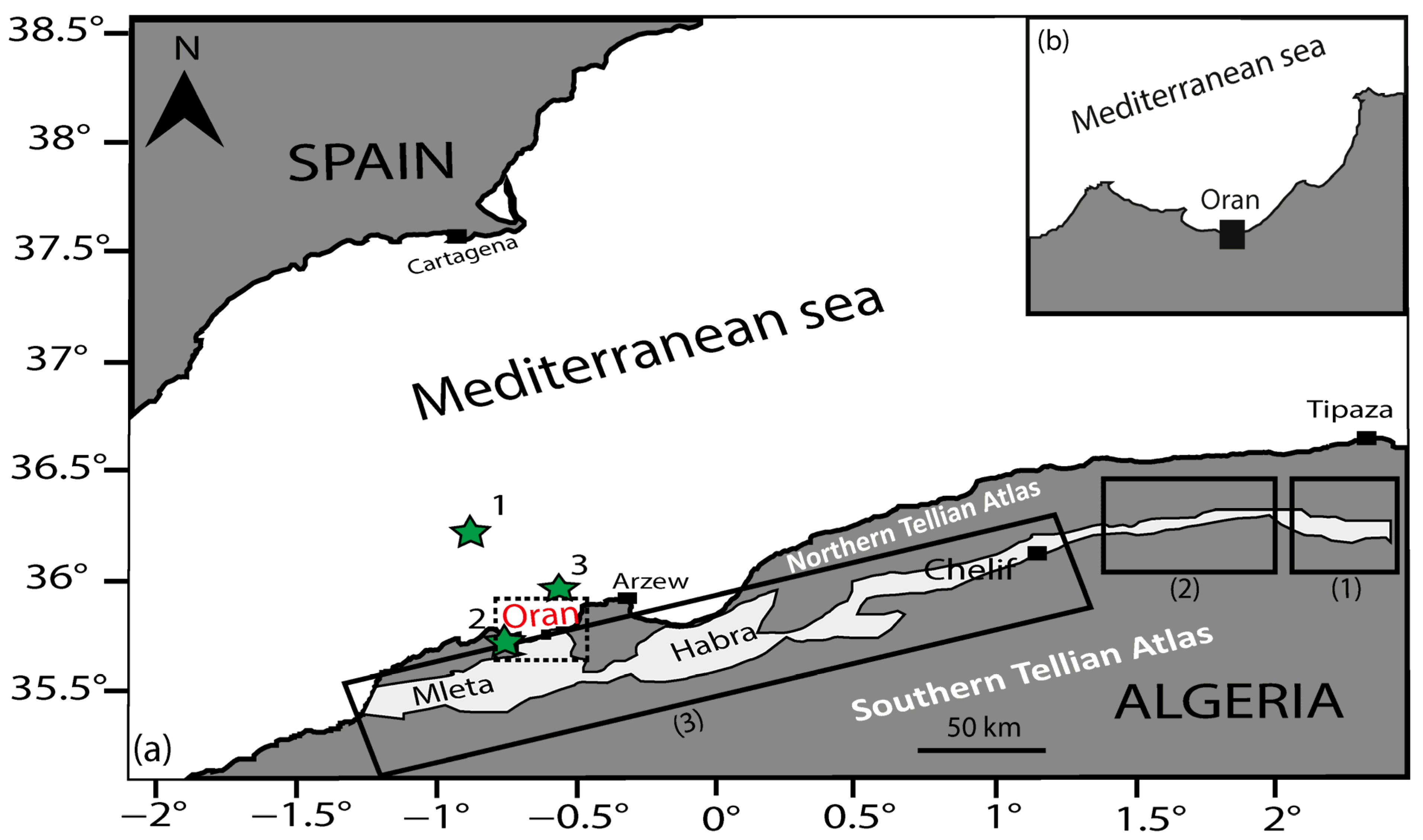
Oran region is located on the coast of the Mediterranean Sea, in the northwest of Algeria. It is part of the Lower-Chelif Basin and is surrounded by the Murdjadjo anticline to the west and by the Arzew massif to the east. In the south, a large Sebkha (saline area) constitutes the southern limit. The Chelif Basin is a large depression that extends over 450 km in an east–west direction and is located in the midst of the northern and southern Tellian Atlas Mountain Belt (Figure 1). The basin is separated into three sub-basins: the Lower Chelif, the Middle Chelif, and the Upper Chelif basins.
The boundary between the convergent African and Eurasian tectonic plates in northern Algeria is well-defined by the seismicity, which is mainly located at the margins of the Neogene basins [1]. Over the years, this territory has witnessed several moderate to strong earthquakes. Oran, in particular, has experienced various moderate earthquakes, including the most significant one in 1790, with an intensity (EMS-98) of I0 = VIII [2], the 1949 earthquake with an intensity of I0 = V [3], and a 5.4 moment magnitude earthquake in 2008 [4].
The Oran region has been the object of numerous geological and geophysical studies. Pomel conducted the first geological study of the Oran region, establishing the stratigraphical units in the area, which led to the first geological map of the region [5]. Later, Thomas proposed a geodynamic evolution model for the western part of the Lower-Chelif Basin using tectonic and sedimentological approaches [6]. Hassani focused on the geological and stratigraphic characteristics of the Great Sebkha located south of Oran [7]. In addition, Bouhadad studied the Murdjadjo fault and concluded that it was responsible for the 1790 earthquake [8].
Different soils and structures respond differently depending on the frequency content of an earthquake [9]. Hence, it is of importance to know their behavior at different frequencies. In the particular case of soil, ambient vibration three-component stations and array deployments are widely applied to investigate and characterize sedimentary basins (e.g., [10,11,12,13,14,15,16,17]) and even some rock sites [18], due to the multiple advantages that these non-invasive techniques offer [19], with regard to other invasive techniques based on downholes, which allow for an accurate estimation of some rock properties but are more expensive and time-consuming [20,21]. Concreting in the northern area of Algeria, these approaches based on ambient vibrations have been employed in the Lower and Middle-Chelif Basins, around 180 km east of our study area, in order to characterize the sedimentary cover (e.g., [22,23,24,25,26]). More recently, a study based on ambient vibration measurements and three-component stations was carried out in the city of Oran [27], as a starting point of our ongoing investigation in this area.
In this work, the Horizontal-to-Vertical Spectral Ratio (HVSR) analysis, together with two of the most common array-based techniques, i.e., the frequency–wavenumber (f-k) and the spatial autocorrelation (SPAC) methods, have been applied in order to characterize the area under study by the uppermost 30 m of the soil column. Thus, one of the objectives of this study is to determine the shear-wave velocity structure in the shallowest sedimentary layers and to establish a variation map of Vs30, where impedance contrasts with the sedimentary cover can result in ground-shaking amplification during strong seismic events.
Furthermore, an empirical equation has been proposed for the region under study in order to predict the average shear-wave velocity in the upper 30 m of the soil column (Vs30) using only the dispersion curve.
The present study is of great importance for the evaluation of the seismic hazard in the Oran region. The results of this investigation constitute an essential resource for ground motions prediction, the assessment of amplification factors, and the realization of various studies dedicated to the mitigation of seismic risk. These results open up ways of effectively reducing the potential impact of seismic events and strengthening protection measures in the zone.

2. Geological Setting

The Lower-Chelif Basin comprises three main plains, the Mleta, Habra, and Chelif plains, separated by a series of plateaus and anticlines [6,28]. The Oran region is located north of the Mleta Plain. It is bordered by the Mediterranean Sea to the north, the Murdjadjo mountain to the west, the Arzew Massif to the east, and the Great Sebkha to the south (Figure 2). In terms of lithology, the Oran region consists of Mio-Plio-Quaternary sediments lying over a Cretaceous bedrock, mainly composed of shales that outcrop to the west in Murdjadjo mountain. The sedimentary series starts with a Miocene formation composed of sandstones, limestones, and marls (e.g., [6,29]). This formation is visible on the right flank of the Murdjadjo mountain and in the northern area of Oran city. The Miocene deposits increase significantly in thickness towards the middle of the Mleta plain [7]. The Miocene deposits are overlaid by a marine Pliocene formation consisting of sandy marls of varying thickness that increase towards the east [6,29]. These deposits are visible to the east of Oran, south of Bir-El-Djir town (Figure 2). The sedimentary series ends with a Quaternary layer consisting of alluviums, limestone, and sands of the Pleistocene age [6,29]. The thickness of these deposits can be determined from wide cliffs that extend across the northern part of the Oran region.

3. Methodology and Data Processing

3.1. Ambient Vibration Data Acquisition

Ambient vibrations were recorded using triangular configuration arrays, with 7 short-period triaxial velocity stations (1 Hz natural frequency, and 100 Hz sampling frequency). The vibrations were recorded for 40 min, at each of the 15 recording sites. The recordings were made in accordance with the recommendations of the SESAME project [30]. The array was arranged as an equilateral triangle, with each side measuring 30 m. The sensors were placed at each vertex, halfway along each side, and an additional sensor was positioned in the center (Figure 3a). In Figure 3b, the theoretical response of the array, together with the aliasing (kmax) and the maximum resolution (kmin/2) wavenumber limits, are presented. This arrangement, as noted by [31], provides a better coverage. The measurements recorded at each site have been used to obtain the HVSR curve, the dispersion curve, and also for directionality analysis.

3.2. HVSR Technique

The HVSR (Horizontal-to-Vertical Spectral Ratio) technique is used to estimate the resonance frequency of the soil and its corresponding amplitude, based on ambient vibration measurements. This method was initially proposed by [32] and further developed by [33]. An updated and detailed review of the HVSR methodology can be found in [34]. To generate the HVSR curve, horizontal and vertical components are required. The recording time has been reduced and split into several windows of a predetermined duration. An anti-triggering algorithm has been employed to select only the stationary windows for further processing. For each selected window, the spectra of the three components (NS, EW, Z) have been calculated and smoothed using the Konno–Ohmachi technique [35]. The horizontal spectrum (H) has been calculated by averaging the NS EW spectra using the quadratic mean. Subsequently, it has been divided by the spectrum of the vertical component (V), providing the corresponding HVSR curve. Combining the results obtained for each analyzed window, the mean HVSR curve, together with the corresponding standard deviation, has been estimated for each station. The described HVSR processing has been carried out using the Geopsy module from the Geopsy package (release 2.10.1) [36]. Finally, an average HVSR curve has also been obtained for each array using the Dinver module from the Geopsy package (release 2.10.1) [36]. The fundamental frequency, which is well correlated with the resonance frequency of the soil, corresponds to the frequency of the HVSR peak.
The directional response of the sites has also been examined by rotating the HVSR curves at all azimuths ranging from 0° to 180°, with a step of 10°. This analysis has been carried out using the Geopsy H/V ROTATE module.

3.3. Frequency–Wavenumber (f-k) Analysis

The f-k analysis is founded on ambient vibration recordings using an array arrangement. It has been described by several authors [37,38,39,40]. By recording data from several sensors simultaneously, this technique allows for the reckoning of surface wave dispersion curves. As in all array techniques, the depth of investigation depends on the dimensions of the array. This method assumes that ambient vibrations are time-stationary in the horizontal level, and only the vertical plane is used to characterize wave propagation properties [38]. The processing is performed in the frequency domain. The seismic wave sources containing the maximum spectral power can be estimated for their slowness and back azimuth using either the Maximum Likelihood Method (MLM), also known as the High Resolution Method (HR), or the Beam Forming Method (BFM), described by [38,40], respectively. In this study, the Beam Forming method was used to estimate the power spectral density.
The surface waves consist of Love and Rayleigh waves. As Love waves are horizontally polarized, Rayleigh waves can be analyzed using only the vertical component of the ambient noise recordings. An f-k analysis was performed using the Geopsy package [36]. First, the coordinates of each of the seven sensors were entered into the WARANGPS module (from Geopsy package, release 2.10.1 [36]) to calculate the transfer function of the array and the theoretical wave number limits (Kmin and Kmax). The signals were then loaded into the Geopsy software to apply the BFM. An anti-triggering algorithm has been used to select the windows. The signals have been divided into windows of different lengths determined by frequency (50 periods). The processing required the specification of grid step and grid size parameters. The grid size corresponded to the Kmax value, which is associated with the aliasing limit, while the grid step was set to Kmin/2, which determined the maximum resolution. In the final step, the dispersion curve was calculated. The same processing steps have been used for all of the fifteen arrays of data.

3.4. Spatial Autocorrelation (SPAC) Technique

The SPAC method is a highly effective technique for determining shear-wave velocity structures in the subsurface using ambient vibration array measurements. It was proposed by [41] and determines the dispersion curve of the surface wave phase velocity. The method assumes that surface waves dominate the ambient vibration signal. The SPAC method is based on several assumptions: (1) ambient vibration waves are stationary in time and the horizontal plane; (2) ambient vibration sources are uniformly distributed; (3) the subsurface Vs structure of the observation arrays consists of horizontal flat layers. The SPAC method requires a circular array of at least four seismographs [31]. Three sensors are distributed around the circumference of the circle and the fourth is located in the center. However, some authors (e.g., [22]), have used additional circles, all centered with the same station for better coverage. In our case, an array of seven stations, forming two circles centered with one station (see Figure 3a), has been used. By recording between the sensors at regular intervals, the mean azimuthal coherence function (i.e., the SPAC coefficient) can be obtained.
The SPAC technique has been carried out with Geopsy software. The SPAC toolbox within the software has been used to define the ring parameters as a first step. After inputting the sensor coordinates, the software automatically establishes a series of sensor pairs distributed in space. Typically, this comprises 21 pairs for 7 sensors. Subsequently, these sensor pairs have been assigned to one or more rings based on optimal matches determined by entering the inner and outer radii. Each ring should consist of at least two pairs and it is recommended to use the maximum number of rings to improve resolution [42]. The signals have been segmented into several windows with a duration of 50 s. The selection of the window was carried out using an anti-triggering algorithm. The subsequent analysis has resulted in the calculation of spatial autocorrelation curves for each ring. Spac2Disp module (from Geopsy package, release 2.10.1 [36]) has been used to visualize the phase velocity histograms derived from the computed spatial autocorrelation values. The final dispersion curve has been derived by selecting the Rayleigh phase velocity values that contributed significantly to the dispersion curve within the Kmin and Kmax ranges. A similar procedure has been applied to the data from the 15 arrays.
Regarding the estimated dispersion curves, some differences are observed with respect to the f-k method. In the SPAC technique, the dispersion curves are picked manually by visually following the maximum energy. In this way, small errors in picking may lead to different dispersion curves. The same differences have already been observed in a previous work in the Middle-Chelif Basin about 200 km east of our study area [22]. The authors pointed out that the SPAC technique appeared to be more sensitive to soft slopes. Therefore, the dispersion curves obtained with the SPAC technique sometimes differ from those obtained with the f-k method when the recording site is on a slope.

3.5. Inversion of Dispersion Curves

The inversion of the obtained dispersion curves allows retrieving of the Vp, Vs, and density models at each of the recording sites. The Rayleigh wave phase velocity depends on these soil properties to a depth of one wavelength [43]. However, the layout and maximum diameter of the sensor array are critical to the success of the inversion process. To better constrain the results, prior knowledge of sediment layer velocities and thicknesses is also required. This information can be obtained from various sources, such as boreholes, geological sections, and seismic refraction techniques.
There are different inversion methods, a review of which can be found at [44,45]. In any case, the inversion process does not generate a unique solution. It generates multiple models with varying degrees of misfit between the calculated dispersion curve and the theoretical dispersion curve of the Rayleigh waves. The velocity model with the lowest misfit is contemplated.
In the present work, the inversion process was performed using the Dinver software from the Sesarray package, which uses the neighborhood algorithm [46]. As the dispersion curves obtained from the f-k and SPAC analyses are almost similar, the dispersion curves obtained from the f-k analysis were used for the inversion process due to their simplicity of calculation compared to the SPAC method, which requires a dispersion curve to be manually picked. The input parameters required for the inversion, including Vp, Vs, and density ranges, as well as the number of layers, have been extracted from the nine boreholes (Figure 2) (Table 1). The borehole data have been obtained from the Laboratoire des Travaux Publics de l’Ouest (LTPO) and the Laboratoire National de l’Habitat et de la Construction (LNHC). A Poisson’s ratio ranging between 0.2 and 0.5 (typical values for soils) was selected. The maximum number of iterations was set to 300, and for each iteration, 100 models have been generated. The experimental mean dispersion curve has been compared to the theoretical curve using a misfit value. The Vs model corresponding to the model with the minimum misfit has been then selected. The misfit is calculated using Equation (1) [47]:
R M S E = i = 1 N v i v i 2 N
where v i is the i -th phase velocity of the obtained curve for each dispersion range, and v i is the i -th phase velocity of the dispersion curve obtained with the raw signal. N represents the number of frequency points considered for the dispersion curve calculation.

3.6. Estimation of the Vs30

The average velocity of the shear waves in the upper layers, and, in particular, at a depth of 30 m, is an important measure in engineering seismology. This velocity is derived from the obtained Vs profiles. The value of Vs30 is derived from Equation (2):
V s 30 = 30 i = 1 N H i V i
where H i represents the i -th layer thickness in meters; Vi represents the i -th layer velocity of shear waves in m/s; and N is the number of layers from the top until 30 m depth.

3.7. Quality Factors Qs and Qp

The quality factor Q is a key parameter in estimating the seismic hazard because it influences the amplitude of ground motion. This parameter will help us to determine the attenuation of seismic waves for each layer. As suggested by [48,49], in the case of a lack of precise constrains, the quality factor Qs can be calculated based on the shear-wave velocity of sediments Vs using Equation (3):
Q s = V s 10
In the field of engineering seismology, the quality factor for P-waves (Qp) is typically assumed to be twice Qs [50].

3.8. Vulnerability Index (Kg)

Liquefaction is a phenomenon to be prevented after an earthquake occurrence, since it is occasionally catastrophic. The liquefaction phenomena is quite common in sedimentary basins, especially with the presence of sandy formations at shallow depths. One methodology for evaluating the risk of liquefaction is the use of the K g vulnerability index, as proposed by Nakamura [51]. In his research, Nakamura [51,52] observed that the vulnerability index ( K g ) values are significantly higher in areas susceptible to liquefaction and landslides. This vulnerability index is estimated from the fundamental frequency of the ground and its amplitude, as illustrated in Equation (4):
K g = ( A 0 ) 2 f 0
where A 0 is the fundamental frequency peak amplitude, and f 0 is the fundamental frequency obtained from the HVSR curve.
Therefore, the K g index could serve as a useful predictor for liquefaction risk when a more robust index is not available.

4. Results and Discussion

4.1. The Soil Fundamental Frequencies

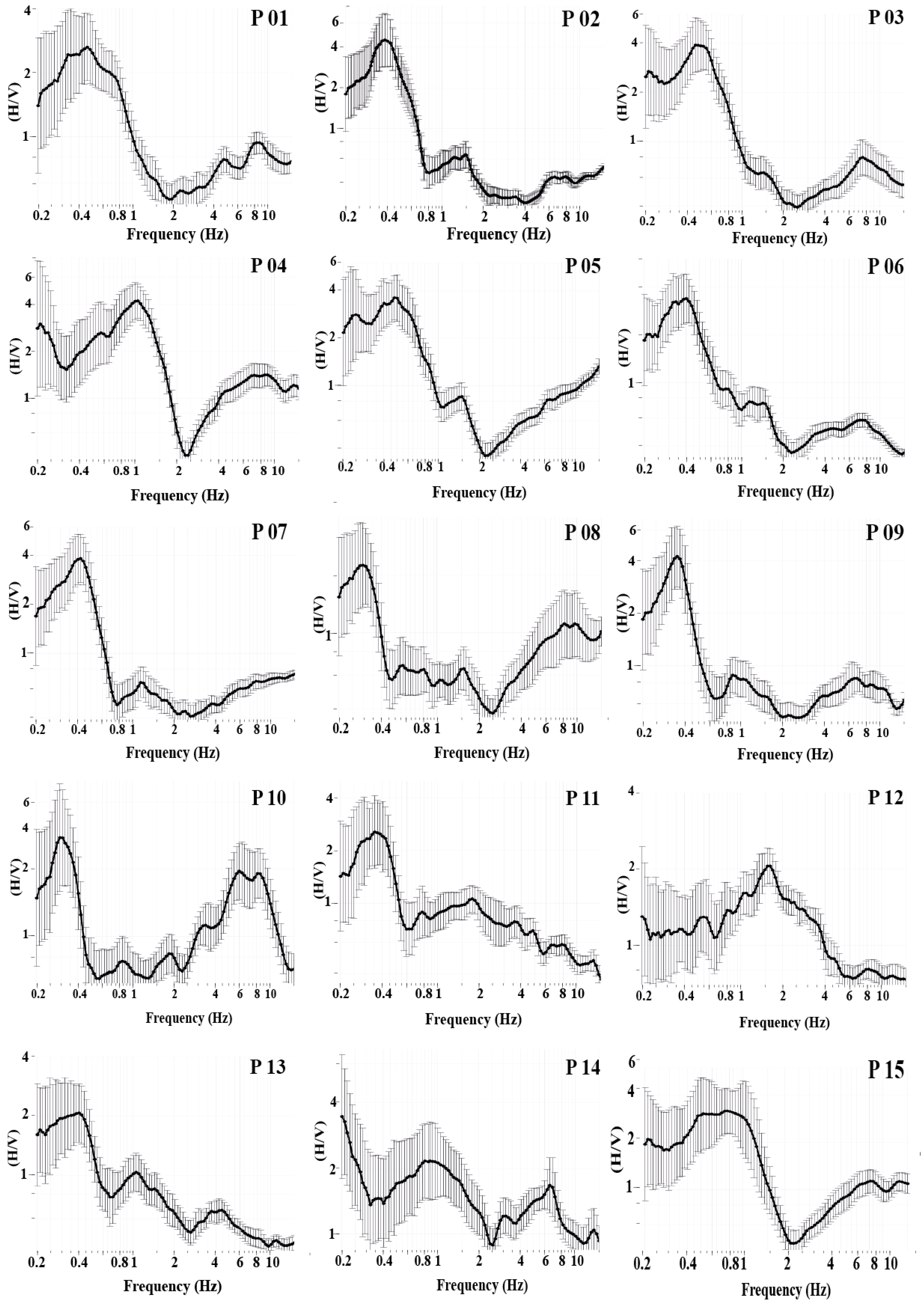
For each site, the HVSR curves of all the stations forming the array (07 stations) have been calculated. The obtained curves, which are relatively similar, have then been averaged to obtain the resonance frequency f0 and the corresponding amplitude A0 of each site with their respective standard deviation (Table 2).
In our study area, the obtained results (Figure 4) show that most HVSR curves have two peaks: the fundamental peak f0 and a secondary peak f1 of lower amplitude.
The fundamental frequency peak varies between 0.3 and 1.6 Hz. This frequency range is in agreement with the fundamental frequency variation maps obtained in a previous measurement campaign [27]. The sites P12 and P14 show the highest values with 1.6 and 0.8 Hz, respectively. These two points are located at the Murdjadjo massif toe in the west of our study area, where a thinning of the sedimentary layers and the Cretaceous of the Murdjadjo mountain are observed [27].
The higher mode frequency peak, f 1 , represents a lower velocity contrast between the Plio-Quaternary and the Miocene sedimentary layers. It has higher values than f 0 and varies between 6.25 and 9 Hz (see Table 2). Higher mode frequency peaks have already been observed before in the Lower-Chelif Basin [26,27].
According to our results (Figure 4), two distinctive groups can be observed: one group with an amplitude A 0 < 3 (sites P1, P8, P10, P11, P12, P13, P14) and another group (P02, P03, P04, P05, P06, P07, P09, P15) with an A 0 value varying between 3 and 4.

4.2. Dispersion Curves

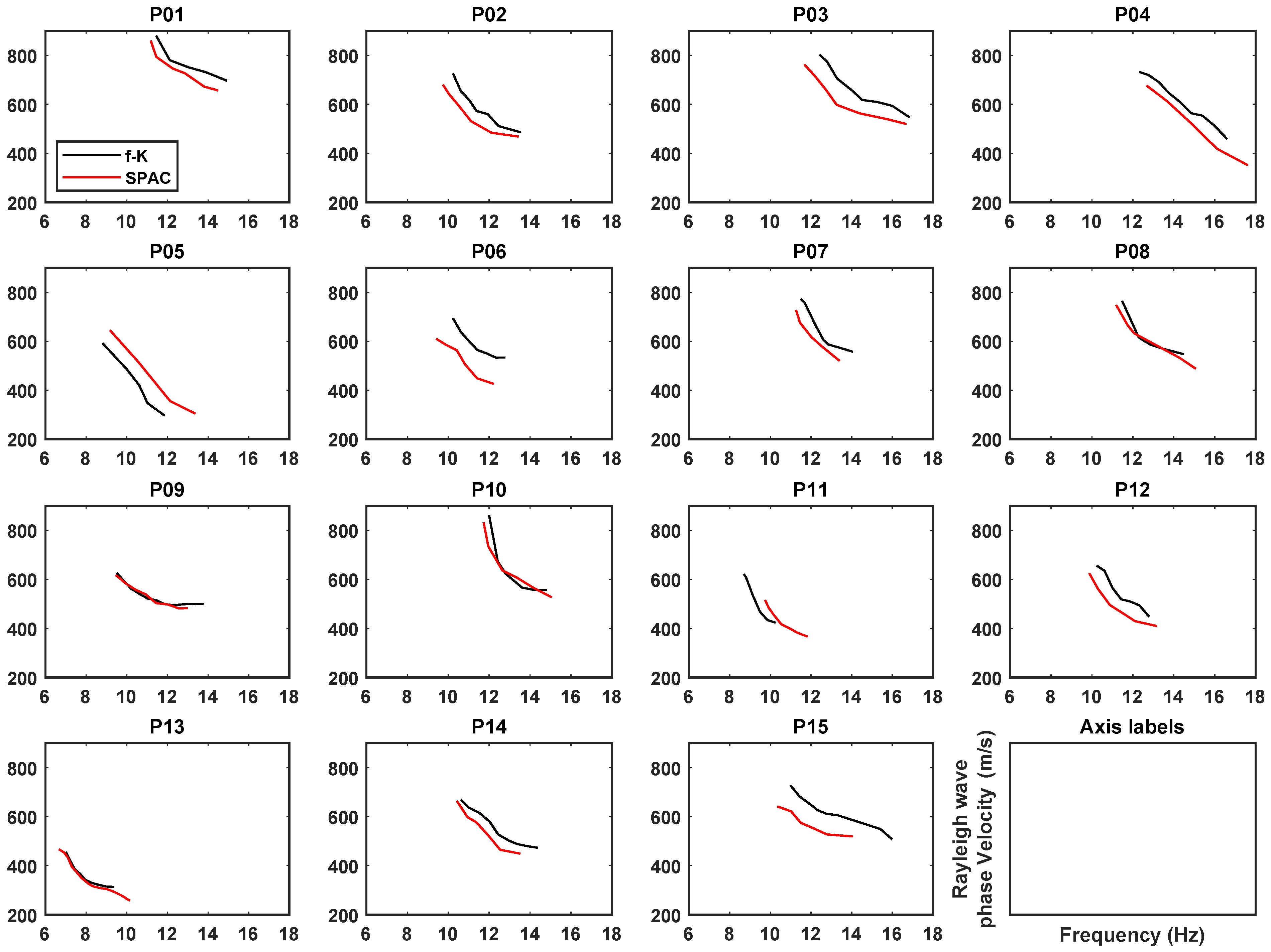
The dispersion curves obtained by applying the f-k and SPAC techniques are shown in Figure 5. The curves are plotted within the theoretical wavenumber limits (Kmin–Kmax), have a frequency range from 6 to 15 Hz, and a corresponding phase velocity range between 250 and 900 m/s.
The obtained frequency results have been compared with previous works carried out in other regions of the study basin. In the work of [22], where the same methods and array geometry were applied, they found frequency values ranging from 5 to 12 Hz. In this case, the lithology in the area under study was similar, except for the recent Quaternary alluviums (topmost layer) that exist in the Middle-Chelif but not in the Oran region. However, it is important to note that an array aperture of 30 m does not allow for investigating higher depths, but only the first tens of meters of the soil column. One of the main limitations of the array techniques with regard to single-station-based techniques is that the array techniques are limited in terms of the investigated depths and depend on the array aperture, so it can be very difficult to find open spaces to perform large aperture array when working on urban areas. Hopefully, the targeted depth in this study is 30 m, and for that, an array aperture of 30 m is enough.
In a previous different work [27], one circular array with a radius of 50 m was deployed in the west part of the study basin. In this case, they obtained fundamental frequency values ranging from 2.7 to 14 Hz. The variation in the frequency range was maybe due to the different local geological conditions of both sites, as well as the different aperture of the arrays.

4.3. Shear-Wave Velocity Models

The Vs velocity profiles shown in Figure 6 have been obtained by inverting the dispersion curves obtained with the f-k analysis. The inversion of the dispersion curves is a delicate process. For example, at some sites, the procedure has to be repeated several times until reaching an acceptable misfit with a reliable and logical shear-wave velocity model. The obtained Vs models are in agreement with the ones obtained in previous works on the Lower- and Middle-Chelif Basins [23,24,25,27].
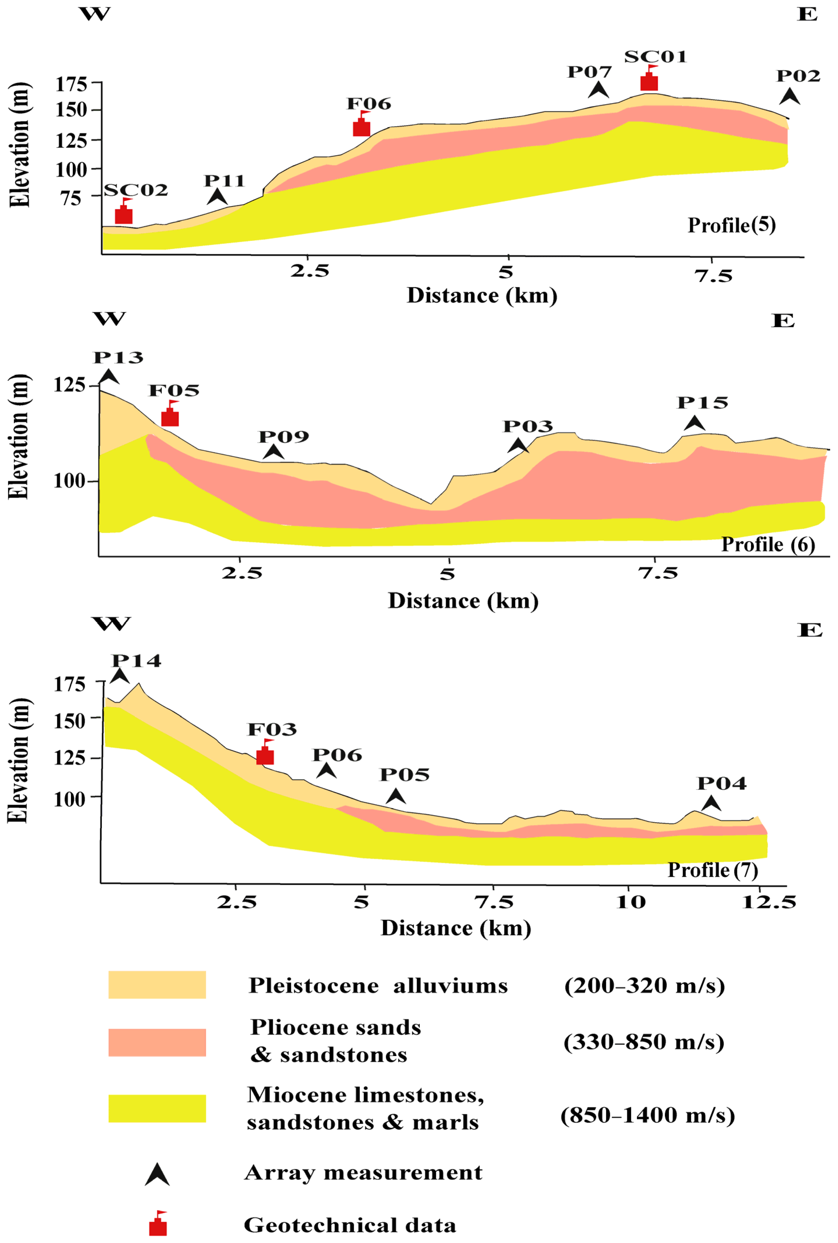
From the lithological boreholes, three sedimentary layers have been identified, belonging to the Quaternary, Pliocene, and Miocene deposits. The obtained Vs models have allowed for inferring the thickness and Vs values for these layers at the topmost 30 m of the soil column. The topmost layer is formed of alluviums and limestones of the Quaternary age. The thickness of this layer ranges from 2 to 20 m, and its velocity changes between 200 and 380 m/s. The sedimentary deposits forming the second layer belong to the Pliocene. They are mainly sandy and vary in thickness from 8 to 36 m, with a velocity ranging between 400 and 800 m/s. This variation is most probably related to the change in facies between sands and sandstones.
The final layer represents the Miocene sediments. It is mainly composed of sandstones, limestones, and marls. Its velocity varies between 850 and 1380 m/s. This variation could be related to the lateral variation from hard limestones to soft marls.
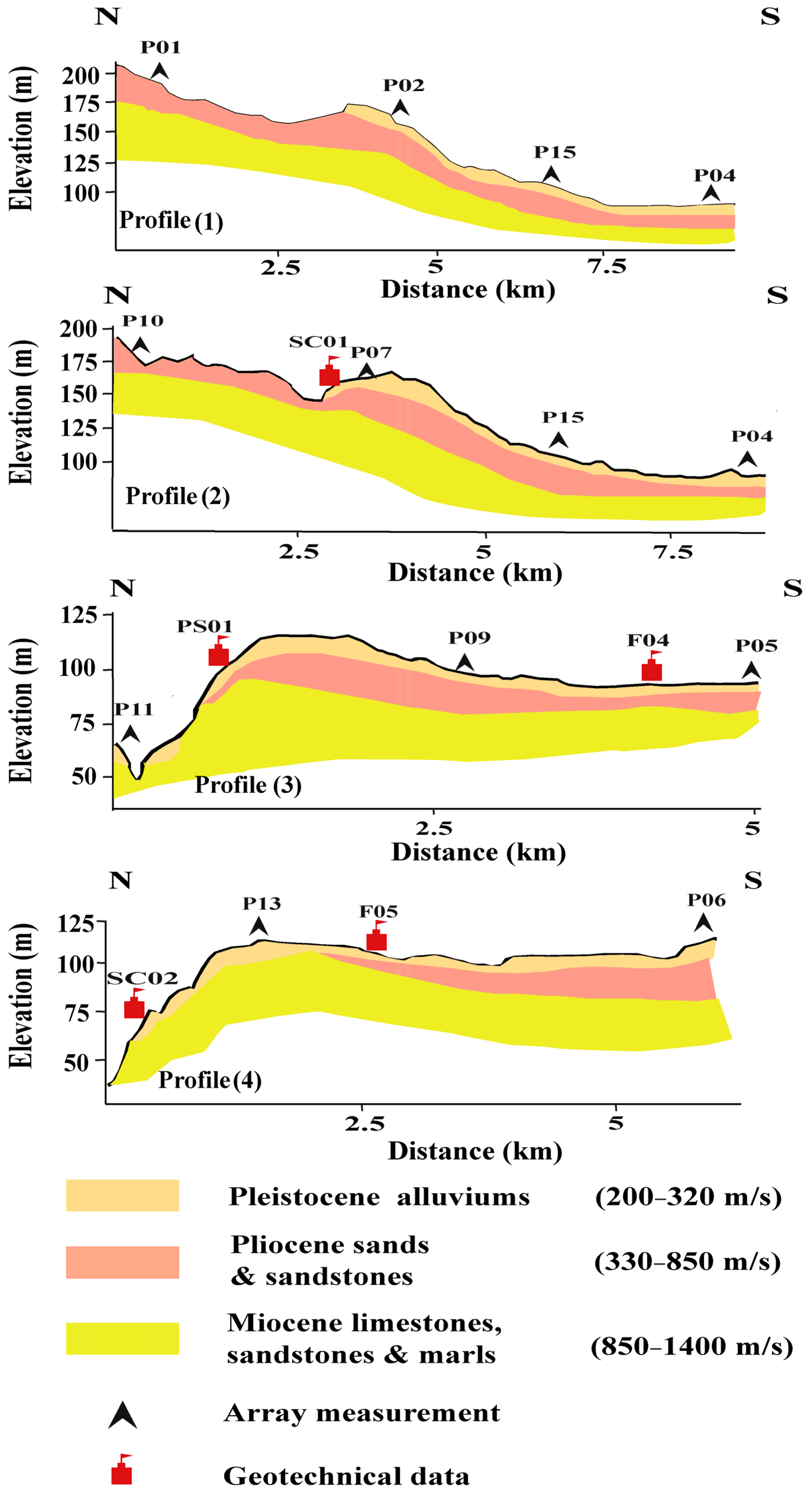
For better illustrating the stratigraphy of the first layers of the velocity model, seven cross-sections (Figure 7) have been established.

4.4. Average Shear-Wave Velocities Vs30

4.4.1. Vs30 and Soil Classification

The Vs30 for each site has been estimated from the obtained Vs models. The results of the Vs30 are shown in Table 2 above.
In the Oran region, the Vs30 values vary between 400 and 670 m/s. This diversity may be due to the lithology and the thickness of each layer.
The obtained results have been compared with those of a previous study carried out in the same area, using HVSR curve inversion [27]. The Vs ranges obtained are approximately similar to the values obtained in this study. However, one must note that array-based techniques provide more accurate results for shallow layers. From the obtained results, it has been noticed that the soils of our study area can be classified according to NEHRP code [51] as soft rock (category C, see Table 3).

4.4.2. Vs30 Predictive Equation for the Oran Region

Predictive equations for Vs30 using the corresponding wavelength can allow for calculating Vs30 values directly without performing the inversion process, which cannot be a straightforward process. It has been widely used in sedimentary basins (e.g., [22,43,54]).
For each site, the average Vs30 has been identified from the obtained Vs model. One must note that the Rayleigh wave-phase velocity depends on the Vs and Vp to a depth of one wavelength [43]. The corresponding wavelength (λ30) is then retrieved from each dispersion curve using Equation (5):
λ 30 = V S 30 f ( V S 30 )
where Vs30 is the average Vs velocity of the first 30 m, calculated from Equation (2). f(Vs30) is the frequency at the Vs30 value, read directly from the dispersion curve plotted in Figure 5.
After the wavelength (λ30) is figured out for each dispersion curve, the average wavelength is obtained as λ ¯ 30 = 47 ± 4   m .
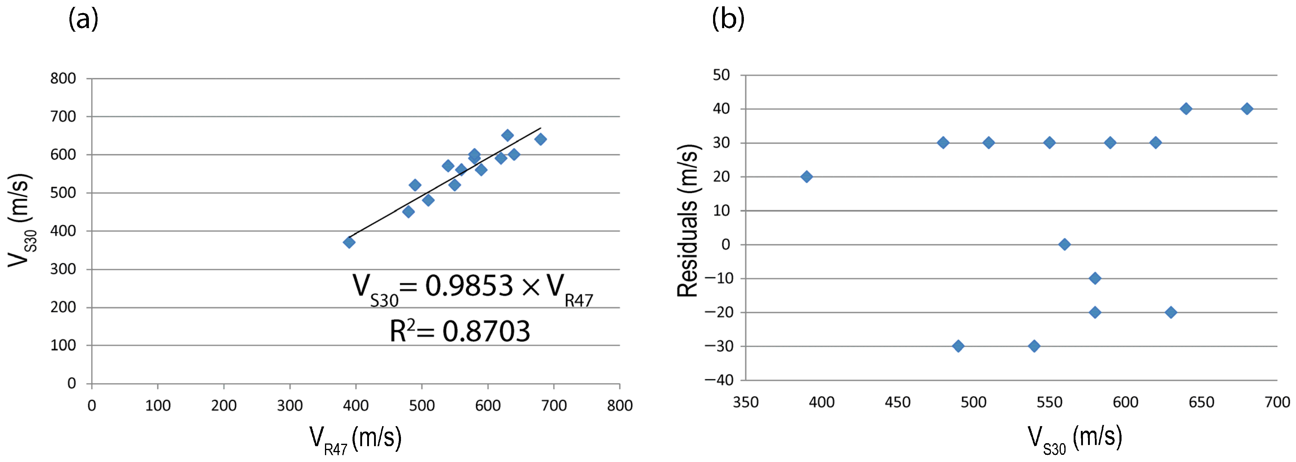
The VR47, which represents the Rayleigh wave velocity corresponding to the wavelength λ ¯ 30 , is presented in Figure 8 as the intersection between the dispersion curve and the V S = λ ¯ 30 · f line (represented by the red color in Figure 8). The Vs30 values were then aligned with the VR47 ones to obtain the most optimal linear fit between them. As a result, Equation (6) was deduced experimentally for the area under study, with a correlation coefficient of R2 = 0.8703.
V S 30 = 0.9853 × V R 47
Figure 9 shows the obtained regression line, as well as the corresponding residual values. The Vs30 values have been obtained with a maximum error not greater than 6.6%, and the associated site classifications have also been established (Table 4).

4.5. Soil Vulnerability Kg

The vulnerability index (Kg) proposed by [51] has been calculated in order to estimate the liquefaction potential. The values obtained in our region vary between about 3 and 53, as shown in Table 2. According to the study of [52], sites where the values of Kg are high have a greater risk of liquefaction. In our study area, the Kg values reflect a relatively low liquefaction potential. However, some areas are more subject to liquefaction than others. Sites with low Kg values are situated to the west of our study area, at the foot of the Murdjadjo mountain (P12 and P14). With regard to the other sites, it can be observed that the risk of liquefaction increases towards the east (P02, P03, P06, P07, P09, P10), where there is a low fundamental frequency with a high corresponding amplitude.

4.6. Directional Site-Effects

The rotational HVSR curves have been analyzed and plotted as polar plots for all stations in Figure 10. These plots illustrate the amplitude variation in the HVSR in the frequency domain, with azimuthal directions ranging from 0° to 360° (Figure 10). 0° represents the north for all stations since all stations are north-oriented.
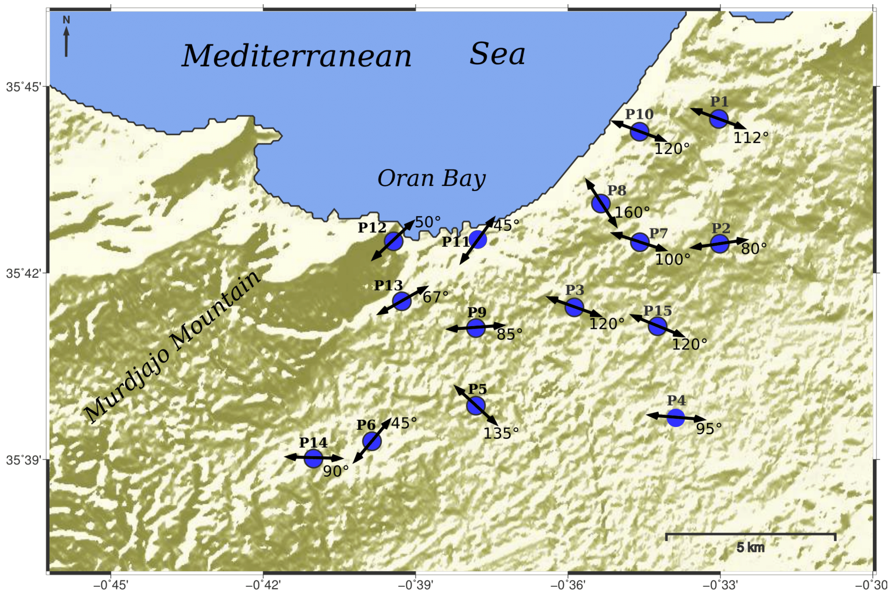
In general, ambient noise is mainly caused by marine waves and man-made activity, such as cars and factory machines. This is probably what could influence the change in directionality in our study area. Anyway, the results show that in most of the analyzed sites, the directionality is approximately perpendicular to the coastline (see Figure 11), which may be related to the sea waves that hit the cliffs bordering the city of Oran from the north.

5. Conclusions

In this study, the shallow subsurface structure of the Oran region has been investigated. The aim has been to characterize the first 30 m of the soil column and provide soil classifications for the study area. For this purpose, a measurement campaign of ambient noise was carried out at 15 sites in the study area using array configurations. Three different methods have been applied (HVSR, f-k, and SPAC techniques) in order to calculate the HVSR curves and Rayleigh wave dispersion curves. The soil parameters that have been provided in this work are the fundamental frequencies and the corresponding amplitudes, the shear-wave velocity model, and the Vs30 values for each site. Additionally, the directionality of the ambient vibration sources has been investigated, and a Vs30 predictive equation for the Oran region has also been provided. All these parameters aim to contribute to a better knowledge of the subsoil structure of the study area.
The main frequency peaks shift between 0.3 and 1.6 Hz, and the corresponding amplitudes between 2 and 4. The high frequency values are found to the west of the study area at the foot of the Murdjadjo mountain, where the sedimentary layers are thin, and the low frequency values are located to the east and in the center of the Oran region.
Ambient vibration array recordings have been used to characterize the shear-wave velocity in the first 30 m of the soil (Vs30) in the Oran region. The SPAC and f-k techniques have allowed for retrieving Rayleigh wave dispersion curves at each of the 15 sites. Both methods produced approximately similar results. The inversion of each curve, along with the introduction of the required input parameters (Vp, Vs, and density ranges, as well as the expected number of layers), resulted in a final Vs model.
In a major part of the study area, the first 30 m of the soil are composed of three sedimentary layers. The topmost layer is composed of Quaternary alluviums, where the Vs value varies between 200 and 380 m/s. The alluvium layer reaches a maximum thickness of 20 m, for example, in borehole F03 in the SW of the study area, and P08 in the north. The second stratum is composed of Pliocene sands and sandstones. The Vs value for this layer changes between 400 and 800 m/s. It can reach a thickness of 24 m in the eastern part of the Oran region. The third layer is made up of Miocene limestones and marls. The Vs value for these formations varies between 850 and 1380 m/s. The Vs values are in accordance with the ones obtained previously using the HVSR technique.
Furthermore, the soils have been classified using the NEHRP criteria for site classification based on the Vs30 variation map. Measurements of Vs30 in the urban environment of the Oran region vary between 400 and 670 m/s. The soil is categorized as very dense soil and soft rock (C).
A Vs30 predictive equation has been proposed to estimate the Vs30 values directly without performing the inversion process, just using the Rayleigh wave phase velocity corresponding to a wavelength of 47 m.
The results obtained in this study provide important information for evaluating the seismic risk in the Oran region, and they could be used in order to update the Algerian seismic code.

Author Contributions

A.S. acquired and processed the data and wrote the first draft of the paper. J.J.G.-M. proposed the methodology and reviewed the paper. F.S. reviewed and supervised the paper. A.Y.-C. provided the acquisition materials and supervised the paper. A.I. helped with array processing and reviewed the paper. All authors have read and agreed to the published version of the manuscript.

Funding

This work has been partially supported by the Conselleria de Educación, Cultura, Universidades y Empleo de la Generalitat Valenciana (project CIAICO/2022/038).

Institutional Review Board Statement

Not applicable.

Informed Consent Statement

Not applicable.

Data Availability Statement

At the data presented in this study ate openly available in Zenodo at https://doi.org/10.5281/zenodo.13308111. Accessed on 12 August 2024.

Acknowledgments

We thank our colleagues from CRAAG for their help during the different measurement campaigns.

Conflicts of Interest

The authors declare no conflicts of interest.

References

  1. Yelles-Chaouche, A.; Boudiaf, A.; Djellit, H.; Bracene, R. La tectonique active de la région nord-algérienne. Comptes Rendus Geosci. 2006, 338, 126–139. [Google Scholar] [CrossRef]
  2. Chimouni, R.; Harbi, A.; Boughacha, M.S.; Hamidatou, M.; Kherchouche, R.; Sebaï, A. The 1790 Oran earthquake, a seismic event in times of conflict along the Algerian coast: A critical review from western and local source materials. Seismol. Res. Lett. 2018, 89, 2392–2403. [Google Scholar] [CrossRef]
  3. Grandjean, A. Séisme d’Algérie de 1940 a 1950. In Annales de L’Institut de Physique du Globe, 3ème Partie, Géophysique VII; IPG: Strasbourg, France, 1954. [Google Scholar]
  4. Benfedda, A.; Bouhadad, Y.; Boughacha, M.; Guessoum, N.; Abbes, K.; Bezzeghoud, M. The Oran January 9th (Mw 4.7) and June 6th, 2008 (Mw 5.4) earthquakes: Seismological study and seismotectonic implication. J. Afr. Earth Sci. 2020, 169, 103896. [Google Scholar] [CrossRef]
  5. Pomel, A. Description Stratigraphique Générale De L’Algerie; Imprimerie de l’Association Ouvrière P: Fontana, Alger, 1889; Volume 1, p. 90. [Google Scholar]
  6. Thomas, G. Géodynamique D’un Bassin Intramontagneux: Le Bassin Du Bas Chéliff occidental (Algérie) Durant le Mio-Plio-Quaternaire; Université de Pau et Pays de l’Adour: Pau, France, 1985. [Google Scholar]
  7. Hassani, M.I. Hydrogeologie D’un Bassin Endoreique Semi-Aride: Le Bassin Versant De La Grande Sebkha D’oran (Algérie). Master’s Thesis, Université Scientifique et Médicale de Grenoble, Grenoble, France, 1987. [Google Scholar]
  8. Bouhadad, Y. The Murdjadjo, Western Algeria, fault-related fold: Implications for seismic hazard. J. Seismol. 2001, 5, 541–558. [Google Scholar] [CrossRef]
  9. Esmaeilabadi, R.; Abasszadeh Shahri, A.; Behzadafshar, K.; Gheirati, A.; Nosrati Nasrabadi, J. Frequency content analysis of the probable earthquake in Kopet Dagh region—Northeast of Iran. Arab. J. Geosci. 2015, 8, 3833–3844. [Google Scholar] [CrossRef]
  10. Rosa-Cintas, S.; Clavero, D.; Delgado, J.; López-Casado, C.; Galiana-Merino, J.J.; Garrido, J. Characterization of the shear wave velocity in the metropolitan area of Málaga (S Spain) using the H/V technique. Soil Dyn. Earthq. Eng. 2017, 92, 433–442. [Google Scholar] [CrossRef]
  11. Rosa-Cintas, S.; Galiana-Merino, J.; Molina-Palacios, S.; Rosa-Herranz, J.; García-Fernández, M.; Jiménez, M. Soil characterization in urban areas of the Bajo Segura Basin (Southeast Spain) using H/V, F–K and ESAC methods. J. Appl. Geophys. 2011, 75, 543–557. [Google Scholar] [CrossRef]
  12. Panzera, F.; Romagnoli, G.; Tortorici, G.; D’Amico, S.; Rizza, M.; Catalano, S. Integrated use of ambient vibrations and geological methods for seismic microzonation. J. Appl. Geophys. 2019, 170, 103820. [Google Scholar] [CrossRef]
  13. Rohmer, O.; Bertrand, E.; Mercerat, E.; Régnier, J.; Pernoud, M.; Langlaude, P.; Alvarez, M. Combining borehole log-stratigraphies and ambient vibration data to build a 3D Model of the Lower Var Valley, Nice (France). Eng. Geol. 2020, 270, 105588. [Google Scholar] [CrossRef]
  14. Wathelet, M.; Jongmans, D.; Ohrnberger, M.; Bonnefoy-Claudet, S. Array performances for ambient vibrations on a shallow structure and consequences over V s inversion. J. Seismol. 2008, 12, 1–19. [Google Scholar] [CrossRef]
  15. Chaaraoui, A.; Chourak, M.; Peláez, J.A.; Cherif, S.-E. Seismic site effects investigation in the urban area of Nador (NE Morocco) using ambient noise measurements. Arab. J. Geosci. 2021, 14, 1937. [Google Scholar] [CrossRef]
  16. Yulians, M.; Tohari, A.; Rochman, J.P.G.N. Development of Seismic microzonation for Rancaekek Sub-District using microtremor method. In IOP Conference Series: Earth and Environmental Science; IOP Publishing: Bristol, UK, 2024; Volume 1373, p. 12017. [Google Scholar] [CrossRef]
  17. Mori, F.; Mendicelli, A.; Moscatelli, M.; Romagnoli, G.; Peronace, E.; Naso, G. A new Vs30 map for Italy based on the seismic microzonation dataset. Eng. Geol. 2020, 275, 105745. [Google Scholar] [CrossRef]
  18. Trichandi, R.; Bauer, K.; Ryberg, T.; Heit, B.; Araya Vargas, J.; von Blanckenburg, F.; Krawczyk, C.M. 3D shear wave velocity imaging of the subsurface structure of granite rocks in the arid climate of Pan de Azúcar, Chile, revealed by Bayesian inversion of HVSR curves. Earth Surf. Dyn. 2024, 12, 747–763. [Google Scholar] [CrossRef]
  19. Boore, D.M. Determining subsurface shear-wave velocities: A review. In Proceedings of the Third International Symposium on the Effects of Surface Geology on Seismic Motion, Grenoble, France, 30 August–1 September 2006; Volume 30, pp. 67–85. [Google Scholar]
  20. Abbaszadeh Shahri, A.; Naderi, S. Modified correlations to predict the shear wave velocity using piezocone penetration test data and geotechnical parameters: A case study in the southwest of Sweden. Innov. Infrastruct. Solut. 2016, 1, 13. [Google Scholar] [CrossRef]
  21. Olutoki, J.O.; Zhao, J.; Siddiqui, N.A.; Elsaadany, M.; Haque, A.E.; Akinyemi, O.D.; Said, A.H.; Zhao, Z. Shear wave velocity prediction: A review of recent progress and future opportunities. Energy Geosci. 2024, 5, 100338. [Google Scholar] [CrossRef]
  22. Issaadi, A.; Saadi, A.; Semmane, F.; Yelles-Chaouche, A.; Galiana-Merino, J.J. Liquefaction potential and Vs30 structure in the Middle-Chelif Basin, Northwestern Algeria, by ambient vibration data inversion. Appl. Sci. 2022, 12, 8069. [Google Scholar] [CrossRef]
  23. Issaadi, A.; Semmane, F.; Yelles-Chaouche, A.; Galiana-Merino, J.J.; Layadi, K. A shear-wave velocity model in the city of Oued-Fodda (Northern Algeria) from Rayleigh wave ellipticity inversion. Appl. Sci. 2020, 10, 1717. [Google Scholar] [CrossRef]
  24. Issaadi, A.; Semmane, F.; Yelles-Chaouche, A.; Galiana-Merino, J.J.; Mazari, A. Shallow S-wave velocity structure in the Middle-Chelif Basin, Algeria, using ambient vibration single-station and array measurements. Appl. Sci. 2021, 11, 11058. [Google Scholar] [CrossRef]
  25. Layadi, K.; Semmane, F.; Yelles-Chaouche, A. S-wave velocity structure of Chlef City, Algeria, by inversion of Rayleigh wave ellipticity. Near Surf. Geophys. 2018, 16, 328–339. [Google Scholar] [CrossRef]
  26. Layadi, K.; Semmane, F.; Yelles-Chaouche, A. Site-Effects Investigation in the City of Chlef (Formerly El-Asnam), Algeria, Using Earthquake and Ambient Vibration Data. Bull. Seismol. Soc. Am. 2016, 106, 2185–2196. [Google Scholar] [CrossRef]
  27. Saadi, A.; Issaadi, A.; Semmane, F.; Yelles-Chaouche, A.; Galiana-Merino, J.J.; Layadi, K.; Chimouni, R. 3D shear-wave velocity structure for Oran city, northwestern Algeria, from inversion of ambient vibration single-station and array measurements. Soil Dyn. Earthq. Eng. 2023, 164, 107570. [Google Scholar] [CrossRef]
  28. Perrodon, A. Etude géologique des bassins sublittoraux de l’Algérie occidentale. Publ. Serv. Carte Géol. de l’Algérie. NS Bull. 1957, 12, 328. [Google Scholar]
  29. Gourinard, Y. Carte Géologique De l’Algérie, Oran, 1/50000, 2nd ed.; Algeria Geological Map Service: Algiers, Algeria, 1952; Volume 159. [Google Scholar]
  30. Acerra, C.; Aguacil, G.; Anastasiadis, A.; Atakan, K.; Azzara, R.; Bard, P.-Y.; Basili, R.; Bertrand, E.; Bettig, B.; Blarel, F.; et al. Guidelines for the Implementation of the H/V Spectral Ratio Technique on Ambient Vibrations Measurements, Processing and Interpretation; European Commission, Project No. EVG1-CT-2000-00026 SESAME; European Commission: Luxembourg, 2004. [Google Scholar]
  31. Okada, H. The Microtremor Survey Method, Geophysical Monograph Series 12; Asten, M.W., Ed.; Society of Exploration Geophysicists: Tulsa, OK, USA, 2003. [Google Scholar]
  32. Nogoshi, M.; Igarashi, T. On the amplitude characteristics of ambient noise (Part 2). J. Seismol. Soc. Jpn. 1971, 24, 26–40. [Google Scholar] [CrossRef]
  33. Nakamura, Y. A Method for Dynamic Characteristics Estimation of Subsurface Using Microtremor on the Ground Surface; Railway Technical Research Institute, Quarterly Reports; Railway Technical Research Institute: Tokyo, Japan, 1989; Volume 30. [Google Scholar]
  34. Molnar, S.; Sirohey, A.; Assaf, J.; Bard, P.-Y.; Castellaro, S.; Cornou, C.; Cox, B.; Guillier, B.; Hassani, B.; Kawase, H. A review of the microtremor horizontal-to-vertical spectral ratio (MHVSR) method. J. Seismol. 2022, 26, 653–685. [Google Scholar] [CrossRef]
  35. Konno, K.; Ohmachi, T. Ground-motion characteristics estimated from spectral ratio between horizontal and vertical components of microtremor. Bull. Seismol. Soc. Am. 1998, 88, 228–241. [Google Scholar] [CrossRef]
  36. Wathelet, M.; Chatelain, J.L.; Cornou, C.; Giulio, G.D.; Guillier, B.; Ohrnberger, M.; Savvaidis, A. Geopsy: A user-friendly open-source tool set for ambient vibration processing. Seismol. Res. Lett. 2020, 91, 1878–1889. [Google Scholar] [CrossRef]
  37. Capon, J. High-resolution frequency-wavenumber spectrum analysis. Proc. IEEE 1969, 57, 1408–1418. [Google Scholar] [CrossRef]
  38. Capon, J.; Greenfield, R.J.; Kolker, R.J. Multidimensional maximum-likelihood processing of a large aperture seismic array. Proc. IEEE 1967, 55, 192–211. [Google Scholar] [CrossRef]
  39. Kelly, E.J.; Levin, M.J. Signal Parameter Estimation for Seismometer Arrays; Massachusetts Institute of Technologies, Lincoln Lab: Lexington, MA, USA, 1964. [Google Scholar]
  40. Lacoss, R.T.; Kelly, E.J.; Toksöz, M.N. Estimation of seismic noise structure using arrays. Geophysics 1969, 34, 21–38. [Google Scholar] [CrossRef]
  41. Aki, K. Space and time spectra of stationary stochastic waves, with special reference to microtremors. Bull. Earthq. Res. Inst. 1957, 35, 415–456. [Google Scholar]
  42. Bettig, B.; Bard, P.; Scherbaum, F.; Riepl, J.; Cotton, F.; Cornou, C.; Hatzfeld, D. Analysis of dense array noise measurements using the modified spatial auto-correlation method (SPAC): Application to the Grenoble area. Boll. Di Geofis. Teor. Ed Appl. 2001, 42, 281–304. [Google Scholar]
  43. Brown, L.; Diehl, J.G.; Nigbor, R.L. A simplified procedure to measure average shear-wave velocity to a depth of 30 meters (VS30). In Proceedings of the 12th World Conference on Earthquake Engineering, Auckland, New Zealand, 30 January–4 February 2000; pp. 1–8. [Google Scholar]
  44. Gosselin, J.M.; Dosso, S.E.; Askan, A.; Wathelet, M.; Savvaidis, A.; Cassidy, J.F. A review of inverse methods in seismic site characterization. J. Seismol. 2022, 26, 781–821. [Google Scholar] [CrossRef]
  45. Yang, X.-H.; Zhou, Y.; Han, P.; Feng, X.; Chen, X. Near-Surface Rayleigh Wave Dispersion Curve Inversion Algorithms: A Comprehensive Comparison. Surv. Geophys. 2024, 45, 773–818. [Google Scholar] [CrossRef]
  46. Wathelet, M. An improved neighborhood algorithm: Parameter conditions and dynamic scaling. Geophys. Res. Lett. 2008, 35, L09301. [Google Scholar] [CrossRef]
  47. Hyndman, R.J.; Koehler, A.B. Another look at measures of forecast accuracy. Int. J. Forecast. 2006, 22, 679–688. [Google Scholar] [CrossRef]
  48. Olsen, K.; Nigbor, R.; Konno, T. 3D viscoelastic wave propagation in the Upper Borrego Valley, California, constrained by borehole and surface data. Bull. Seismol. Soc. Am. 2000, 90, 134–150. [Google Scholar] [CrossRef]
  49. Schlotterbeck, B.A.; Abers, G.A. Three-dimensional attenuation variations in southern California. J. Geophys. Res. Solid Earth 2001, 106, 30719–30735. [Google Scholar] [CrossRef]
  50. Riga, E.; Makra, K.; Pitilakis, K. Aggravation factors for seismic response of sedimentary basins: A code-oriented parametric study. Soil Dyn. Earthq. Eng. 2016, 91, 116–132. [Google Scholar] [CrossRef]
  51. Nakamura, Y. Seismic vulnerability indices for ground and structures using microtremor. In Proceedings of the World Congress on Railway Research, Florence, Italy, 16–19 November 1997. [Google Scholar]
  52. Nakamura, Y. Real-time information systems for seismic hazards mitigation UrEDAS, HERAS and PIC. Q. Rep.-Rtri 1996, 37, 112–127. [Google Scholar]
  53. Council, B.S.S. NEHRP Recommended Provisions for Seismic Regulations for New Buildings and Other Structures (FEMA 450); Building Seismic Safety Council: Washington, DC, USA, 2003. [Google Scholar]
  54. Konno, K.; Kataoka, S.I. An estimating method for the average S-wave velocity of ground from the phase velocity of Rayleigh wave. Doboku Gakkai Ronbunshu 2000, 2000, 415–423. [Google Scholar] [CrossRef]
Figure 1. (a) Location of Oran region in Mleta plain in Lower-Chelif Basin. The rectangle (1) corresponds to Upper, (2) Middle, and (3) Lower-Chelif Basin, which is comprised between the Northern and Southern Tellian Atlas Mountains. The numbered green stars, 1, 2, and 3, are the 1790, 1949, and 2008, respectively, main seismic events in the region. The study area (Oran region) is indicated by the dashed frame and zoomed in (b).
Applsci 14 07364 g001
Figure 2. A geological map of Oran and the enclosing region, modified from [6,29]. Black filled circles are array locations. The nine available boreholes from F01 to F06 and SC01 to SC03 (blue triangles) and the seismic refraction profile PS01 show the thickness of the sediment layers and their velocity (Vs). The red lines are cross-sections.
Applsci 14 07364 g002
Figure 3. (a) Array geometry. Blue dots are seismic stations. (b) Theoretical response. The large and small black circles correspond to Kmax and Kmin/2 values, respectively.
Applsci 14 07364 g003
Figure 4. The average HVSR curves obtained for each of the arrays analyzed (P1 to P15), whose position is indicated in Figure 2. For each curve, the thick black line corresponds to the averaged HVSR curve; meanwhile, the vertical gray bars reflect the standard deviation values at each frequency.
Applsci 14 07364 g004
Figure 5. The dispersion curves estimated for each recording site using the f-k analysis (black line) and the SPAC method (red line). The dispersion curves are plotted in terms of the Rayleigh wave phase velocities (m/s) as a function of frequency (Hz). Each plot corresponds to the results obtained at the different analyzed sites (P1 to P15). In Figure 2, the position of these sites is shown.
Applsci 14 07364 g005
Figure 6. Rayleigh wave dispersion curves (left panels) and Vs models (right panels) estimated for all the analyzed sites from P1 to P15. In the left panels, the experimental dispersion curve is represented by the mean value (black thick line) and the corresponding standard deviation (vertical black bars). On the other hand, the theoretical dispersion curves associated with the different estimated Vs models are represented by dark gray curves (related with the models with a minimum misfit plus 10%) and light gray curves (related with all the tested models). In the right panels, the Vs model with the minimum misfit (black thick line), the Vs models with the minimum misfit plus 10% (dark gray lines), and all the tested models (light gray lines) are shown.
Applsci 14 07364 g006
Figure 7. Two-dimensional shear-wave velocity profiles 1–7, from up to down, respectively. The location of these cross-sections is represented with red lines in Figure 2. The colored areas represent the lithology of the sedimentary formations, with a shear-wave velocity range for each layer.
Applsci 14 07364 g007aApplsci 14 07364 g007b
Figure 8. Dispersion curves (black lines) obtained from the f-k analysis and already shown in Figure 5 above. The VR47 results from the intersection between the dispersion curve and the red line corresponding to the wavelength of 47 m.
Applsci 14 07364 g008
Figure 9. (a) Regression line (Vs30 vs. VR47) and the derived equation. R2 is the correlation coefficient. (b) The respective residual values.
Applsci 14 07364 g009
Figure 10. HVSR polar diagrams. The color bar indicates the HVSR amplitude variations, and the dashed line represents the estimated directionality.
Applsci 14 07364 g010
Figure 11. Spatial distribution of the array sites (blue circles) and directionality of the registered ambient noise (black arrows). The direction where the HVSR curve reaches the maximum amplitude for the resonant frequency is also indicated for each site.
Applsci 14 07364 g011
Table 1. Input parameters used for the inversion: number of layers and Vp, Vs, and density ranges.
Sedimentary LayersVP Range (m/s)VS Range (m/s)Density Range (kg/m3)
Quaternary alluviums200–1100150–3801700–2100
Pliocene sands and sandstones450–2500300–9001900–2200
Miocene marls, sandstones, and limestones1200–3000800–14502100–2400
Table 2. Geotechnical characteristics calculated for each site.
SiteLon (°)Lat (°)f0 (Hz)A0f1 (Hz)A1KgVs30 (m/s)Soil Class (NEHRP)Qs30
P01−0.55049235.7412580.47 ± 0.012.63 ± 0.328.50 ± 0.340.95 ± 0.0814.72620C62
P02−0.55024735.7077880.38 ± 0.014.50 ± 0.4653.29590C59
P03−0.59794535.6907430.47 ± 0.023.95 ± 0.347.44 ± 0.230.80 ± 0.3333.20630C63
P04−0.56459035.6611021.05 ± 0.024.22 ± 0.288.00 ± 0.451.40 ± 0.1416.96680C68
P05−0.63021235.6644280.48 ± 0.013.60 ± 0.2927.00510C51
P06−0.64312035.6548570.39 ± 0.013.38 ± 0.417.16 ± 0.220.60 ± 0.0329.29540C54
P07−0.57639035.7082260.41 ± 0.013.90 ± 0.0137.10580C58
P08−0.58923535.7185370.30 ± 0.012.25 ± 0.159.00 ± 0.341.10 ± 0.2116.88640C64
P09−0.63019335.6852220.35 ± 0.004.30 ± 0.036.63 ± 0.450.86 ± 0.0852.83550C55
P10−0.57645535.7377820.31 ± 0.012.80 ± 0.046.60 ± 0.501.90 ± 0.3425.29580C58
P11−0.62962735.7089650.35 ± 0.022.56 ± 0.1018.72480C48
P12−0.65720335.7084271.58 ± 0.022.05 ± 0.1202.66530C53
P13−0.65446535.6923680.40 ± 0.022.20 ± 0.0712.10390C39
P14−0.68347335.6502350.87 ± 0.012.20 ± 0.436.52 ± 0.201.67 ± 0.1505.04560C56
P15−0.57055235.6857020.76 ± 0.023.60 ± 0.357.83 ± 0.351.35 ± 0.4417.05580C58
Table 3. Soil classification according to NEHRP code [53].
Vs (m/s)Soil TypeSoil Classification
Vs > 1500Hard rockA
760 < Vs ≤ 1500RockB
360 < Vs ≤ 760Very dense soil and soft rockC
180 < Vs ≤ 360Stiff soilD
Table 4. Evaluation of the Vs30 predictive equation based on the Vs30 values obtained in this study.
SiteVs30 (m/s)Predicted Vs30 (m/s)Error (%)Actual Site
Classification
Predicted Site
Classification
P16205905.00%CC
P25905605.30%CC
P36306503.00%CC
P46806406.25%CC
P55104806.20%CC
P65405705.30%CC
P75805901.70%CC
P86406006.60%CC
P95505205.80%CC
P105806003.30%CC
P114804506.60%CC
P125305205.80%CC
P133903705.40%CC
P145605600.00%CC
P155806003.30%CC
Disclaimer/Publisher’s Note: The statements, opinions and data contained in all publications are solely those of the individual author(s) and contributor(s) and not of MDPI and/or the editor(s). MDPI and/or the editor(s) disclaim responsibility for any injury to people or property resulting from any ideas, methods, instructions or products referred to in the content.