Article

A Mathematical Model for Conical Hopper Mass Efficiency

1
Department of Manufacturing Systems, Faculty of Mechanical Engineering and Robotics, AGH University of Krakow, A. Mickiewicza 30, 30-059 Krakow, Poland
2
Department of Design Machine and Automotive Engineering, Lviv Polytechnic National University, 79013 Lviv, Ukraine
*
Authors to whom correspondence should be addressed.
Appl. Sci. 2024, 14(16), 7373; https://doi.org/10.3390/app14167373 (registering DOI)
Submission received: 3 August 2024 / Revised: 18 August 2024 / Accepted: 19 August 2024 / Published: 21 August 2024
(This article belongs to the Section Chemical and Molecular Sciences)

Abstract

:
Almost every branch of industry, at a certain point, utilizes omnifarous materials in their granular form. A key constituent in many bulk material logistic systems is the hopper, which usually acts as a buffering component. In order to achieve the desired throughput, the geometry of the particular hopper must be carefully determined. Considering the geometric properties of the given hopper, the inclination of the walls and the outlet orifice characteristics are the pivotal determinants of hopper functionality. In this paper, the authors have developed an analytical model of the conical hopper’s mass efficiency and compared the model with the experimental results for two distinctive granular materials. The model inputs were: the density of the bulk material, critical angle of material repose, generatrix inclination angle of the cone, and diameter of the circular outlet. The experiment was conducted according to a 32 full factorial design. The repeatability of the results was examined according to Cochran’s theorem and the adequacy of the data was evaluated via Fisher’s criterion, which confirmed the quality of the mathematical model. The error of the developed model does not exceed 4.5%.

1. Introduction

Each technological process has its own intrinsic type of bottleneck; however, in the transportation of granular materials, the “bottleneck” is less figurative than in any other system, since many of the logistic subsystems can exhibit a retardant effect. When considering bulk material handling and storage systems (MH&SS), the flow of the granular material has been analyzed for many years; however, problems with blockage, segregation, dead zones, and material collapses are present to this day, as can be seen in Figure 1.
Many studies have been carried out using discrete element methods (DEM) in order to analyze the structure of the granular material through the hopper’s neck, the distribution of stresses along the hopper’s walls, the effect of the particle shape on the discharge of the hopper, etc. Chou et al. [1] investigated the pressure of a moving granular layer acting on the side walls. The force fluctuation at the boundary of a two-dimensional granular flow was investigated by Longhi et al. [2]. Chen et al. [3] developed a correlation between the flow pattern and the wall pressure in a full-scale granular solids storage hopper. González-Montellano [4] analyzed velocity patterns while filling and discharging the silo and used the mass flow index, which was later expanded by Magalhães et al. [5], who developed local mass flow in order to distinguish granular material velocity profiles along the main axis of the conical hopper and along its wall. Zuriguel et al. [6] made a very interesting observation on the similarities between particle clogging and sheep passing through a gate. Cleary and Sawley [7] investigated the unloading process in a two-dimensional hopper on different materials and geometric parameters and found that the outflow rate depends mainly on the given particle shape.
Zhu and Yu [8] applied the discrete element method (DEM), supported by the averaging method, for a quantitative study of the velocity and stress distribution found in hopper flow. Their results demonstrate that DEM can be used for macroscopic analysis of the dynamic behavior of hopper flow. Using large-scale DEM computer simulations, Landry et al. [9] examined the variations in vertical stress profiles with dimensionality. Several researchers have investigated the impact of particle shape selection on hopper discharge. Masson and Martinez [10] showed that round particles have low resistance and shear forces. Studies related to the influence of the mechanical properties of particles on the filling and unloading of granular materials from hoppers were conducted by Goda and Ebert [11], as well as by Yang and Hsiau [12]. Additionally, the behavior of granular discrete flow during the filling and unloading of materials from hoppers was studied by Hirshfeld and Rapaport [13], Nguyen et al. [14], Parisi et al. [15], and Sykut et al. [16].
Analytical methods for studying the parameters of hopper systems dominate the development of hopper design. For instance, Rogovskii et al. [17] conducted the mathematical modeling of grain mixtures in tasks for optimizing the kinematic parameters of a tipping hopper, treating the grain mixture as a quasi-liquid. Kobyłka et al. [18] conducted experimental research and DEM modeling of the discharge of dispersed materials from a hopper. Gella et al. [19] found that the relationship between mass flow and the nature of contacts between beads, friction, or differences in kinetic energy per unit area is non-trivial, requiring further research to clarify these issues. Numerical modeling of the flow from a hopper, as reported by Danczyk et al. [20], demonstrated the high sensitivity of flow to contact parameters and the necessity of detailed local studies to confirm the results of numerical modeling.
Regarding the theory of pressure in storage hoppers, research has been conducted on the storage and transportation of grain and discrete materials using mathematical modeling, laboratory experiments, finite element modeling, and discrete element numerical modeling. Experimental studies, particularly those by Parafiniuk et al. [21], Wang et al. [22], and Kobyłka et al. [23], focused on grain particles such as corn, rapeseed, and sunflower seeds, while Chen et al. [3], Guo et al. [24], Sun et al. [25], Wang et al. [26], An et al. [27], and Wu et al. [28] investigated the processes found in hoppers with dispersed materials such as iron ore, coal fragments, and fine sands. Experiments were conducted on storage hoppers under loading and unloading conditions. It was found that the distribution of static pressure in storage hoppers is consistent with the results obtained using Janssen’s formula. Wang et al. [29] performed discrete element numerical modeling for storing particle stocks, including rapeseed, fine sand, glass marbles, and coal. Bembenek et al. [30] used DEM to model the briquetting process of fine-grained materials in a roll press [31]. The creation of a simulation model based on DEM software enabled an analysis of performance and numerical modeling of the process.
Karwat et al. [32] indicated that when modeling the flow of bulk materials, it is important to correctly define the input parameters on a macroscopic scale. In other words, it is more crucial to represent the behavior of the entire flow of the mixture than the behavior of individual particles. Boikov et al. [33] also emphasized the importance of determining the behavior of a material on a macroscopic scale. They noted that for spherical particles, it is necessary to determine seven input parameters for modeling, which—if they vary linearly—can be described using an approximation function containing these parameters.
Developing a reliable simulation model that closely approximates the actual behavior of bulk materials requires proper calibration of the model’s input parameters, such as particle shape and size, friction and restitution coefficients, or bulk density, which ought to be determined experimentally under laboratory conditions [32,34,35].
It is clear that by knowing the characteristics of the flow process of discrete materials from the silo, one can assess the accuracy of the dosing systems installed at the material outlet from the hopper. Dmytriv et al. [36] investigated how the pressure of the dispersed material above the dosing mechanism, located at the material’s outlet from the hopper, affects the dosing performance. It is worth noting that the properties of the material significantly impact the accuracy of modeling. Numerical studies indicate the influence of modeling parameters on flow rate, which makes it difficult to compare the model with the actual process. For example, friction coefficients are uneven on the surface of the particle, and the restitution coefficient is only significant for ideal spheres that are characterized by uniform material parameters. Furthermore, the issue of how to transfer simulation results to real systems largely remains unresolved [37]. Another unresolved issue regarding the flow of material from the hopper is the conditions for unobstructed flow and the shape of the arch (or dome) of stagnant material above the outlet after the flow has stopped. Therefore, developing an analytical model of the movement of a material particle along a conical disc, based on the kinematic characteristics of the dosing process and the characteristics of the dosing material, and experimentally confirming this model is relevant for the calculation and design of working bodies of this type. Such dosing systems are widely used in the processes of dosing and mixing in the pharmaceutical, chemical, food production, material, and mixture processing industries, as well as in agriculture [38].
The purpose of this research work was to develop a mathematical model of the mass flow efficiency of bulk materials, considering the various design parameters of the hopper and physico-mechanical characteristics of the material. The theoretical model was also tested via experimental verification.

2. Materials and Methods

2.1. Mathematical Model of Granular Material Discharge from the Conical Hopper—Assessments

The most commonly occurring types of hoppers have either round or rectangular cross-sections. For the sake of the model, the authors assumed an elementary volume with a height of dx (Figure 2). The granular material’s characteristics, such as particle size, shape, stiffness, surface characteristics, water absorption, etc., were indirectly taken into account as the following coefficients:
β—particle packing angle,
f—coefficient of friction of the material mass against the hopper walls,
ϼ—bulk material density,
φ—external friction angle (material-to-hopper-walls).
The force counteracting the movement of the given elementary volume of granular material inside the hopper in circular cross-section with a vertical load can be described as in Formula (1):
F T = f · N = f · π · D · d x · p N
where:
  • F T —frictional force [N];
  • N —force normal to the hopper walls [N];
  • f —coefficient of friction of material sliding along the hopper walls [–];
  • D —diameter of the hopper outlet [m];
  • d x —height of the considered elementary volume [m];
  • p N —pressure of the material acting on the hopper walls [Pa].
The gravitational force acting on the elemental volume can be calculated using Formula (2):
G = π · D 2 4 · ρ · g · d x
where:
  • G —weight of the elemental volume [N];
  • ρ —density of the granular material [ kg m 3 ];
  • g —acceleration of gravity [ m s 2 ].
The normal pressure acting on the hopper walls surface can be described by Formula (3):
p N = 1 · p · tan β
where:
  • β —packing angle of the material inside the hopper [°];
  • p —pressure acting on the upper surface of the elemental volume [Pa].
The force of inertia can be described with Formula (4):
F i = ρ · π · D 2 4 · d x · a
where:
  • a —downward acceleration of the elemental volume [ m s 2 ]
According to the d’Alembert principle, the forces acting on the rheonomic set of material points are, at a given moment, balanced by the force of inertia; thus, k = 1 n F k x = 0 .
All the projections of the forces were summed on the X axis (Formula (5)), taking into account the force generated by the pressure p and (p + dp) on the upper and lower faces of the selected elementary volume:
p · π · D 4 p + d p d x · d x · π · D 2 4 + G F i F T = 0 .
Combining all the dependencies from Formulas (1)–(4) into Formula (5), the following equation can be obtained:
p · π · D 4 p + d p d x · d x · π · D 2 4 + G F i F T = 0 .
After division by π · D 2 4 · d x and the necessary rearrangement, a differential equation is needed to find the pressure (Formula (7)):
d p d x + 8 · f · tan β D · p = ρ · g a .
When the acceleration a is considered to be constant, Formula (7) can be integrated into the following form:
p = ρ · ( g a ) · D 8 · f · tan β + C · e 8 · f · tan β D · x
where:
  • x—distance from the origin to the cross-section [m].
The integration constant can be found using the boundary conditions when x = 0 and p = 0. Then, Formula (8), which is used for finding the pressure in an arbitrary section of a vertical cylindrical hopper, will take the form:
p = ρ · ( g a ) · D 8 · f · tan β · 1 e 8 · f · tan β D · x   .
Under conditions where a ≈ 0 and at a sufficient depth (x ≫ D) in the hopper, the pressure is practically constant and is determined by Formula (10):
p = ρ · a · D 8 · f · tan β   .
For a hopper with a variable cross-sectional diameter of dm, the elementary volume of mass can be represented by Formula (11):
d m = ρ · S x · d x ,
where:
  • d x —height of the elemental volume (EV) of the granular material [m];
  • S x —cross-sectional area, varying with the displacement of the EV [m2].
The change in the diameter of the silo with a circular cross-section along the height is calculated using Formula (12):
d x = D 0 2 · x · tan α ,   0 x H 1   , tan α = D 0 D / 2 · H 1
where:
  • D 0 —diameter at the upper part of the hopper [m];
  • D —diameter at the lower part of the hopper [m];
  • H 1 —hopper height [m];
  • α —inclination angle of the cone generatrix [°].
Thus, the cross-sectional area of the round hopper will be equal to:
S x = π · D 0 2 · x · tan α 2 4
To model the velocity of the dispersed material movement in the hopper, the following differential equation of motion for the elementary volume was developed:
ρ · S x · d x · d v d t = p · S x p + d p · S x + d s + + d G 2 · p · tan β + ψ · H ( x ) · d x H x = tan β + φ · π · d x
where:
  • d v d t —acceleration of the material in elemental volume [ m s 2 ];
  • d s —increase in the cross-sectional area of the elementary volume [m2];
  • d G —weight of the elementary volume of the material [N];
  • ψ —angle of repose for the considered material [°];
  • φ —angle of the given material’s external friction (material-to-vessel) [°].
Dividing the equation of motion for the elementary volume (Formula (13)) by S(x)⋅dx, a first-order differential equation with variable coefficients is obtained:
ρ · d v d t = d p d x K x · p + ρ · g
where:
  • K ( x ) —the simplifying coefficient [ 1 m ].
K x = 1 S x · d S d x + 2 · h ( x ) S ( x ) · tan β + ψ
The efficiency of the hopper outlet can be expressed through the velocity v of the movement of the elementary volume of material, using Formula (16):
Q b n = ρ · S · v
After rearranging Formula (16) and taking the derivative with respect to time:
d v d t = 1 ρ · S · d Q b n d t Q b n ρ · S 2 · d S d x · d x d t .
Since d x d t = v , Formula (17) can take an alternative form:
d v d t = 1 ρ · S · d Q b n d t Q b n 2 ρ 2 · S 3 · d S d x
Hereafter, the authors assumed that the process is stationary, with Qbn = const; therefore, d Q b n d t = 0 . Substituting Formula (18) into Formula (14), a first-order differential equation with variable coefficients with respect to pressure p(x) is obtained. This allows the researcher to investigate the pressure distribution along the height of the hopper analytically:
d p d x + K ( x ) · p = ρ · g + Q b n 2 ρ · S 3 · d S d x
The expression in Formula (19) can be represented by the sum of two solutions:
p ( x ) = p 1 ( x ) + p 2 ( x )
where:
  • p 1 ( x ) —a solution to the homogenous Equation (21);
  • p 2 x —a partial solution of the non-homogeneous Equation (19).
d p 1 d x + K ( x ) · p 1 = 0
The solution of the homogeneous Equation (21) has the form:
p 1 ( x ) = B · e 0 x K ( z ) · d z
where:
  • B—constant;
  • K(z)—a coefficient determined by Formula (15);
  • z—the integration variable.
The partial solution of p2(x) can be found by using the method for variation of the constant C, as follows:
p 2 ( x ) = C · e 0 x K ( z ) · d z
d p 2 ( x ) d x = d C d x · e 0 x K ( z ) · d z C · K ( x ) · e 0 x K ( z ) · d z
Substituting (24) and (23) into Equation (19), it becomes possible to find the function C(x), introducing an additional new integration variable (y):
C x = 0 x ρ · g + Q b n 2 ρ · S 3 · d S y d y · e 0 y K z · d z · d y .
Taking into account the dependencies of (22), (23), (25), one can obtain:
p x = e 0 x K z · d z · B + 0 x ρ · g + Q b n 2 ρ · S 3 · d S y d y × e 0 y K z · d z · d y .
The constant B is found from the boundary conditions. Since at x = 0, p = pA (atmospheric pressure), then B = pA. The next step is to calculate the integrals included in Formula (26) by first establishing the coefficient K(x) for a circular cross-section of the hopper, based on Formula (15):
p 1 ( x ) = B · e 0 x K ( z ) · d z
where:
  • H = D 0 2 · tan α —the height of the whole cone [m].
Assuming that K 0 = 2 · 2 · tan β + ψ · tan α + φ tan α 1 is constant:
0 x K x · d x = 0 x K 0 · d x H x = K 0 · ln H H x ;
Z 4 x = e 0 x K z · d z · d y = 0 x H H y K 0 · d y = H K 0 1 · H H x K 0 1 1 ,   [ m ]
Z 5 ( x ) = e 0 x K ( x ) · d x = H H x K 0
Z 6 x = 1 ρ 0 x d S y S 3 d y · e 0 y K z · d z · d y = 1 ρ 0 x 2 · H K 0 π 2 · tan α 4 · H y K 0 5 · d y =         = 2 · H 4 ρ · π 2 · tan α 4 · K 0 + 4 · H H x K 0 + 4 1 ,   1 k g · m .
Given the calculated integrals of (28), (29), and (30), Equation (26), when used for finding the pressure, will take the following form:
p ( x ) = p A · H x H K 0 + ρ · g · H K 0 1 · H x H H x H K 0 32 · Q b n 2 ρ · D 0 4 · π 2 · K 0 + 4 · H x H 4 H x H K 0
Formula (31) determines the pressure of material at the outlet of the hopper. When taking into account Formula (27) and the dependence H = H 0 + H 1 from Figure 1, the equation for the overall efficiency of material throughput from the conical hopper with a given generatrix angle can be developed as follows:
Q b n = p ( H 1 ) p A · D D 0 K 0 ρ · g · A z 1 · ρ · D 0 4 · π 2 32 · A z 2  
where:
  • A z 1 = D 2 · tan α · K 0 1 · D 0 K 0 1 D K 0 1 K 0 K 0 1 , [m];
  • A z 2 = 1 K 0 + 4 · D 0 K 0 + 4 D K 0 + 4 D 4 · D 0 K 0 , [m];
  • p ( H 1 ) = ρ · g · D 8 · f · tan β · 1 e 8 · f · tan β D · H 1 , [Pa];
  • ρ —density of the material, [ kg m 3 ];
  • pa—atmospheric pressure, [Pa].
Once the mass efficiency is modeled, Formula (32) can be introduced to a simulation of the flow of bulk materials from a conical hopper.

2.2. Mathematical Model of Granular Material Discharge from the Conical Hopper—Simulation

In order to evaluate the developed model, the authors decided to test it using two different bulk materials (buckwheat grains), assuming six different hopper generatrix angles and five different hopper outlet diameters. The simulation parameters for simulation regarding the material, along with parameters referring to the hopper setup, are listed in Table 1.
Figure 3 and Figure 4 show the modeling results. The cone angle of the hopper, starting from 4°, affects the discharge performance. At an angle of α = 2°, the bulk material discharges under the influence of gravity, and the friction angles do not impact the discharge process significantly. At an angle of α = 4°, the discharge performance of the bulk material is 1.5–2 times lower than at α = 2°.
The modeling results shown in Figure 3 and Figure 4 indicate that it is better to select a cone angle for the hopper within the range of α ( 4 ° , 10 ° ) and a discharge orifice diameter of D ( 0.05   m ,   0.1   m ) .
For buckwheat (Figure 4), the discharge performance increases with the diameter of the discharge orifice but decreases along with the increase in the generatrix angle of the hopper. When the orifice diameter is D = 0.025 m, the discharge efficiency is minimal. Increasing the diameter of the orifice to 0.05 m results in an average increase in discharge performance by 4.5 to 5.0 times. Therefore, using a discharge opening diameter of 0.025 m could be impractical in the design of a round conical hopper.
This pattern of bulk material discharge, as shown by the modeling results, applies to both buckwheat and coal. In order to confirm the results from the simulation, the authors decided to perform a full-factorial-designed experiment. The purpose of conducting the full-factorial-designed experiment was to verify the correspondence between the analytical modeling of the discharge performance of bulk materials from a circular conical hopper and the data from experimental studies.

3. Results

The research was conducted using a full-factorial designed experiment. The experimental methodology was based on [35], taking into account the significance of each factor and decoding the terms of regression dependence into the coefficients of the equation for the natural values of the factors. The response criterion was the parameter of the discharge performance of bulk material from the circular conical hopper, QK [kg/s], the factors being the diameter of the hopper’s discharge orifice, D, m –> x1, and the cone angle of the hopper, α, degrees –> x2. The values of the factors and the coding coefficients, calculated according to the theory of experimental design, are presented in Table 2.
To ensure that the design matrix has the property of orthogonality, a column in Table 2 with corrected-level values of x was introduced. These values were calculated using Formula (33):
x i 2 = x i 2 x i 2 N   .
The matrix for calculating the coefficients of the equation is presented in Table 2, where columns 2–6 constitute an orthogonal design matrix, and columns 7 and 8 contain the response values of the experiment. According to the data from Table 3, the coefficients of the regression equation were calculated. The values of the regression coefficients characterize the contribution of each factor to the value of the response function and are calculated by the following formulas:
b 1 = x 1 · y 6 ,   b 2 = x 2 · y 6 ,
b 22 = x 2 2 · y 2 ,   b 11 = x 1 2 · y 2 ,   b 12 = x 1 · x 2 · y 12 ,
b 0 = y 9 0.67 · b 11 0.67 · b 22   .
The results of the calculation of the coefficients of the regression equation are given in Table 4 and Table 5. To use the natural values of factors in the regression equation, the linear terms of the equation were converted from coded values into natural ones. They were determined by the formula given in [36].
With the decoded values of the coefficients of the regression equation, the model of the productivity of the flow of bulk material from a cone hopper of circular section will accordingly take the following form for physical variable factors.
For crushed coal:
Q k 2 = 3.557 + 1039.99 · D 6.0 · α + 9066.72 · D 2 + 0.667 · α 2 140 · D · α .
For buckwheat:
Q k 1 = 0.123 + 338.676 · D 1.692 · α + 3253.28 · D 2 + 0.196 · α 2 44 · D · α .
The regression equations for the dependence of the discharge performance of bulk material from a conical hopper with a circular cross-section on the factors are graphically represented in Figure 5 and Figure 6, corresponding to regression dependencies (37) and (38), respectively.
The correctness of the experiment and the experimental data obtained were then checked. The repeatability of the experiment was demonstrated by carrying it out three times with the same levels of input factors. The results of the analysis of experimental data regarding the significance of the coefficients of the regression equations according to Student’s t-test proved the significance of the coefficients of the equation. An evaluation of the adequacy of models with Fisher’s F-test showed the reproducibility of the model.

4. Discussion

Based on the results of theoretical modeling and experimental research, the following conclusions can be drawn:
  • The results of the experimental studies are consistent with the results of the theoretical modeling.
  • The difference between the experimental data and the theoretical modeling results does not exceed 5%.
Both naturally and intuitively, as the cone angle of the hopper increases, the discharge rate of the bulk material decreases. For buckwheat, the discharge rates for different discharge opening diameters and cone angles are as follows:
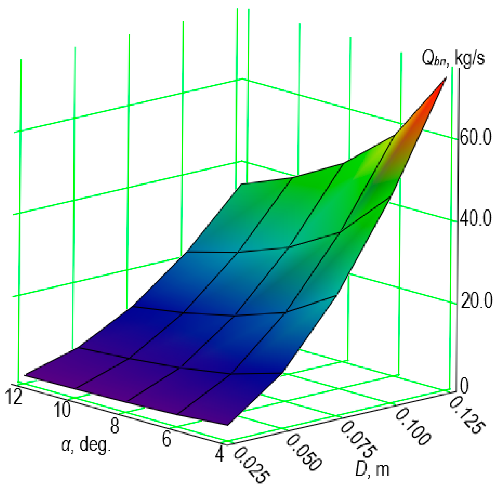
  • For D = 0.05 m and α = 4°, Qk = 12.36 kg/s;
  • For D = 0.05 m and α = 12°, Qk = 4.56 kg/s;
  • For D = 0.10 m and α = 4°, Qk = 49.33 kg/s;
  • For D = 0.10 m and α = 12°, Qk = 21.67 kg/s.
Regarding crushed coal, the discharge rates for the same discharge opening diameters and cone angles are as follows:
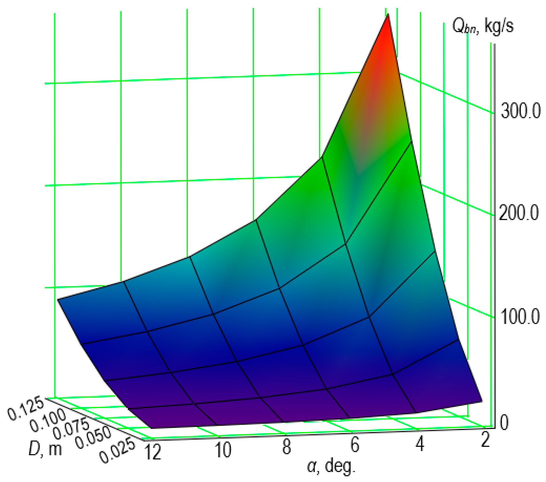
  • For D = 0.05 m and α = 4°, Qk = 36.15 kg/s;
  • For D = 0.05 m and α = 12°, Qk = 11.59 kg/s;
  • For D = 0.10 m and α = 4°, Qk = 144.3 kg/s;
  • For D = 0.10 m and α = 12°, Qk = 55.08 kg/s.
Thus, increasing the cone angle of the conical hopper decreases the discharge rate of bulk materials. It is evident that increasing the diameter of the hopper’s discharge opening increases the discharge rate of bulk material from it.

5. Conclusions

Using the designed experiments in experimental research allows for establishing the correspondence between the analytical model of the discharge rate of bulk material from a round conical hopper and the physical discharge rate of bulk material from a round conical hopper.
The developed analytical dependence (Formula (32)) is an accurate mathematical model for the discharge of bulk material from a round conical hopper. To use it, the physical and mechanical characteristics of the bulk material need to be known. These include:
  • the density of the bulk material;
  • the angle of particle packing in the overall mass;
  • the external friction angle of the material;
  • the internal friction angle of the material (angle of repose);
  • the coefficient of sliding friction of the bulk material against the hopper walls.
Additionally, the design dimensions of the hopper must be known prior to calculation. These include:
  • the generatrix angle of the hopper cone;
  • the height of the hopper;
  • the diameter of the discharge orifice.
Inaccuracies in the physical and mechanical characteristics of the bulk material will contribute to increased inaccuracies when calculating the discharge rate of the bulk material from the hopper.

Author Contributions

Author Contributions: Conceptualization, V.D., M.B. and V.B.; methodology, M.B., R.H., V.D., J.P. and V.B.; software, V.D., M.B., V.B. and R.H.; validation, V.D. and V.B.; investigation, M.B., V.B. and V.D.; writing—original draft preparation, R.H., M.B., V.D. and J.P.; writing—review and editing, M.B. and J.P.; visualization, J.P., V.D., and V.B.; project administration, V.D. and M.B.; funding acquisition, M.B. All authors have read and agreed to the published version of the manuscript.

Funding

This research received no external funding.

Institutional Review Board Statement

Not applicable.

Informed Consent Statement

Not applicable.

Data Availability Statement

The data presented in this study are available on request from the corresponding author.

Acknowledgments

This article originated as part of a research internship from 22 January 2024 until 21 June 2024 by Michał Bembenek at the Department of Machine Design and Automotive Engineering, Lviv Polytechnic National University in Ukraine in 2024.

Conflicts of Interest

The authors declare no conflicts of interest.

References

  1. Chou, C.S.; Tzeng, C.Y.; Smid, J.; Kuo, J.T.; Hsiau, S.S. Experimental study of moving granular bed: Wall stress measurement. In Proceedings of the 14th ASCE Engineering Mechanics Division Conference, Austin, TX, USA, 21–24 May 2000. [Google Scholar]
  2. Longhi, E.; Easwar, N.; Menon, N. Large force fluctuations in a flowing granular medium. Phys. Rev. Lett. 2002, 89, 045501. [Google Scholar] [CrossRef] [PubMed]
  3. Chen, J.F.; Rotter, J.M.; Ooi, J.Y.; Zhong, Z. Correlation between flow pattern and wall pressures in a full scale silo. Eng. Struct. 2006, 29, 2308–2320. [Google Scholar] [CrossRef]
  4. González-Montellano, C.; Gallego, E.; Ramírez-Gómez, Á.; Ayuga, F. Three dimensional discrete element models for simulating the filling and emptying of silos: Analysis of numerical results. Comput. Chem. Eng. 2012, 40, 22–32. [Google Scholar]
  5. Magalhães, F.G.; Atman, A.P.; Moreira, J.G.; Herrmann, H.J. Analysis of the velocity field of granular hopper flow. Granul. Matter 2016, 18, 33. [Google Scholar]
  6. Zuriguel, I.; Parisi, D.R.; Hidalgo, R.C.; Lozano, C.; Janda, A.; Gago, P.A.; Peralta, J.P.; Ferrer, L.M.; Pugnaloni, L.A.; Clément, E.; et al. Clogging transition of many-particle systems flowing through bottlenecks. Sci. Rep. 2014, 4, 7324. [Google Scholar]
  7. Cleary, P.W.; Sawley, M.L. DEM modelling of industrial granular flows: 3D case studies and the effect of particle shape on hopper discharge. Appl. Math. Model. 2002, 26, 89–111. [Google Scholar] [CrossRef]
  8. Zhu, H.; Yu, A. A numerical study of the stress distribution in hopper flow. China Particuol. 2003, 1, 57–63. [Google Scholar] [CrossRef]
  9. Landry, J.W.; Grest, G.S.; Plimpton, S.J. Discrete element simulations of stress distributions in silos: Crossover from two to three dimensions. Powder Technol. 2004, 139, 233–239. [Google Scholar] [CrossRef]
  10. Masson, S.; Martinez, J. Effect of particle mechanical properties on silo flow and stresses from distinct element simulations. Powder Technol. 2000, 109, 164–178. [Google Scholar] [CrossRef]
  11. Goda, T.J.; Ebert, F. Three-dimensional discrete element simulations in hoppers and silos. Powder Technol. 2005, 158, 58–68. [Google Scholar] [CrossRef]
  12. Yang, S.C.; Hsiau, S.S. The simulation and experimental study of granular materials discharged from a silo with the placement of inserts. Powder Technol. 2001, 120, 244–255. [Google Scholar] [CrossRef]
  13. Hirshfeld, D.; Rapaport, D.C. Granular flow from a silo: Discrete-particle simulations in three dimensions. Eur. Phys. J. E 2001, 4, 193–199. [Google Scholar] [CrossRef]
  14. Nguyen, V.D.; Cogné, C.; Guessasma, M.; Bellenger, E.; Fortin, J. Discrete modeling of granular flow with thermal transfer: Application to the discharge of silos. Applied Thermal. Engineering 2009, 29, 1846–1853. [Google Scholar] [CrossRef]
  15. Parisi, D.R.; Masson, S.; Martinez, J. Partitioned distinct element method simulation of granular flow within industrial silos. J. Eng. Mech. 2004, 130, 71–779. [Google Scholar] [CrossRef]
  16. Sykut, J.; Molenda, M.; Horabik, J. DEM simulation of the packing structure and wall load in a 2-dimensional silo. Granul. Matter 2008, 10, 273–278. [Google Scholar] [CrossRef]
  17. Rogovskii, I.L.; Shymko, L.S.; Voinash, S.A.; Sokolova, V.A.; Rzhavtsev, A.A.; Andronov, A.V. Mathematical modeling of grain mictures in optimatization tasks of the dump bunker’s kinematic parameters. IOP Conf. Ser. Earth Environ. Sci. Chem. Ecol. Oil Gas Eng. 2020, 548, 062055. [Google Scholar] [CrossRef]
  18. Kobyłka, R.; Wiacek, J.; Parafiniuk, P.; Horabik, J.; Banda, M.; Stasiak, M.; Molenda, M. Discharge Flow of Spherical Particles from a Cylindrical Bin: Experiment and DEM Simulations. Processes 2021, 9, 1860. [Google Scholar] [CrossRef]
  19. Gella, D.; Maza, D.; Zuriguel, I. Role of particle size in the kinematic properties of silo flow. Phys. Rev. E 2017, 95, 052904. [Google Scholar] [CrossRef]
  20. Danczyk, M.; Meaclem, T.; Mehdizad, M.; Clarke, D.; Galvosas, P.; Fullard, L.; Holland, D. Influence of contact parameters on Discrete Element method (DEM) simulations of flow from hopper: Comparison with magnetic resonance imaging (MRI) measurements. Powder Technol. 2020, 372, 671–684. [Google Scholar] [CrossRef]
  21. Parafiniuk, P.; Molenda, M.; Horabik, J. Discharge of rapeseeds from a model silo: Physical testing and discrete element method simulations. Comput. Electron. Agric. 2013, 97, 40–46. [Google Scholar]
  22. Wang, X.W.; Yang, Z.J.; Shu, X.F.; Feng, J.L. The static contact statuses between granular materials and flat-bottomed steel silos. Powder Technol. 2013, 235, 1053–1059. [Google Scholar]
  23. Kobylka, R.; Molenda, M.; Horabik, J. Loads on grain silo insert discs, cones, and cylinders: Experiment and DEM analysis. Powder Technol. 2019, 343, 521–532. [Google Scholar]
  24. Guo, J.; Roberts, A.W.; Prigge, J.D. Experimental investigation of wall pressure and arching behavior under surcharge pressure in mass- flow hoppers. Powder Technol. 2014, 258, 272–284. [Google Scholar]
  25. Sun, W.W.; Zhu, J.P.; Zhang, X.D.; Wang, C.C.; Wang, L.; Feng, J. Multi-Scale experimental study on filling and discharge of squat silos with aboveground conveying channels. J. Stored Prod. Res. 2020, 88, 101679. [Google Scholar]
  26. Wang, X.W.; Li, B.; Xie, J.C.; Xia, R. Discharge flow and dynamic stress of coal particles in rectangular silos with pyramidal hopper. Int. J. Coal Prep. Util. 2020, 40, 513–523. [Google Scholar]
  27. An, H.Q.; Wang, X.; Fang, X.H.; Liu, Z.; Liang, C. Wall normal stress characteristics in an experimental coal silo. Powder Technol. 2021, 377, 657–665. [Google Scholar]
  28. Wu, Y.P.; Liu, M.Y.; Xie, P.S.; Wang, H.W.; Hu, B.S. Three-Dimensional physical similarity simulation experiments for a transparent shaft coal pocket wall in coal mines. ACS Omega 2022, 7, 16442–16453. [Google Scholar]
  29. Wang, P.J.; Zhu, L.; Zhu, X.L. Flow pattern and normal pressure distribution in flat bottom silo discharged using wall outlet. Powder Technol. 2016, 295, 104–114. [Google Scholar]
  30. Bembenek, M.; Buczak, M.; Baiul, K. Modelling of the Fine-Grained Materials Briquetting Process in a Roller Press with the Discrete Element Method. Materials 2020, 15, 4901. [Google Scholar] [CrossRef]
  31. Karwat, B.; Machnik, R.; Niedźwiedzki, J.; Nogaj, M.; Rubacha, P.; Stańczyk, E. Calibration of bulk material model in Discrete Element Method on example of perlite D18-DN. Eksploat. I Niezawodn.—Maint. Reliab. 2019, 21, 351–357. [Google Scholar]
  32. Baiul, K.; Vashchenko, S.; Khudyakov, A.; Bembenek, M.; Zinchenko, A.; Krot, P.; Solodka, N. A Novel Approach to the Screw Feeder Design to Improve the Reliability of Briquetting Process in the Roller Press. Eksploat. I Niezawodn.—Maint. Reliab. 2023, 25, 67967. [Google Scholar] [CrossRef]
  33. Boikov, A.V.; Savelev, R.V.; Payor, V.A. DEM Calibration Approach: Design of experiment. J. Phys. Conf. Ser. 2018, 1015, 032017. [Google Scholar]
  34. Hlosta, J.; Jezerská, L.; Rozbroj, J.; Žurovec, D.; Nečas, J.; Zegzulka, J. DEM Investigation of the Influence of Particulate Properties and Operating Conditions on the Mixing Process in Rotary Drums: Part 1—Determination of the DEM Parameters and Calibration Process. Processes 2020, 8, 222. [Google Scholar] [CrossRef]
  35. Wang, X.; Yi, J.; Zhou, Z.; Yang, C. Optimal Speed Control for a Semi-Autogenous Mill Based on Discrete Element Method. Processes 2020, 8, 233. [Google Scholar] [CrossRef]
  36. Dmytriv, V.; Bembenek, M.; Banha, V.; Dmytriv, I.; Dzienniak, D.; Nurkusheva, S. Modeling of the Efficiency of the Centrifugal Conical Disk Dispenser of Bulk Materials. Materials 2024, 17, 1815. [Google Scholar] [CrossRef]
  37. Dmytriv, V.T.; Dmytriv, I.V.; Horodetskyy, I.M.; Horodniak, R.V.; Dmytriv, T.V. Method of theory of dimensions in experimental research of systems and processes. INMATEH—Agric. Eng. 2021, 65, 233–240. [Google Scholar] [CrossRef]
  38. Dmytriv, V.T.; Dmytriv, I.V.; Horodetskyy, I.M.; Yatsunskyi, P.P. Adaptive cyber-physical system of the milk production process. INMATEH—Agric. Eng. 2020, 61, 199–208. [Google Scholar] [CrossRef]
Figure 1. Illustration of the same system with (a) a clogged hopper with obtuse walls and (b) a modified hopper with much steeper walls (courtesy of the MGTechnic company).
Applsci 14 07373 g001
Figure 2. Diagram of the hopper and the forces acting on the dispersed material of the elementary volume.
Applsci 14 07373 g002
Figure 3. Dependence of the discharge performance (Qbn) of buckwheat from a hopper of diameter D of the discharge orifice and the hopper cone angle of α. Please note the Qbn scale when comparing the results with Figure 4.
Applsci 14 07373 g003
Figure 4. Dependence of the discharge performance (Qbn) of crushed coal from a hopper of diameter D of the discharge orifice and the hopper cone angle α. Please note the Qbn scale when comparing the results with Figure 3.
Applsci 14 07373 g004
Figure 5. Dependence of the discharge performance (Qbn) of crushed coal from the hopper on the diameter D of the discharge opening and the cone angle α of the hopper. Please note the Qk1 scale when comparing the results with Figure 6.
Applsci 14 07373 g005
Figure 6. Dependence of the discharge performance (Qbn) of buckwheat from the hopper on the diameter D of the discharge opening and the cone angle α of the hopper. Please note the Qk1 scale when comparing the results with Figure 5.
Applsci 14 07373 g006
Table 1. Selected characteristics of the tested materials and the hopper.
FeatureBuckwheatCoal
Density, ρ [ k g m 3 ]560900
Particle packing angle, β [°]5635
External friction angle, φ [°]1525
Internal friction angle, ψ [°]1734
Material-wall friction coefficient [-]0.470.47
Cone angle, α [°], step: 2°4–122–12
Hopper height, [m]0.50.5
Hopper orifice diameter, [m], step: 0.025 m0.025–0.1250.025–0.125
Table 2. Levels of variation of factors and their code values in the planned experiment.
FactorsDesignationUnitLevels of FactorsVariation
Interval
UpperNullLower
Code Values
+10−1
Hopper orifice diameter, Dx1m1.00.0750.0500.025
Hopper cone generatrix angle, αx2deg.10862
Table 3. Design matrix of the experiment for a two-factor second-order model of the dependence of the discharge performance of bulk materials from a circular conical hopper.
Experiment No.x1x2x1·x2 ( x 1 ) 2 ( x 2 ) 2 y1 (QK), Buckwheat,
kg/s
y2 (QK), Coal,
kg/s
1+1+1+10.33330.333325.065.3
20+10−0.66670.333313.435.0
3−1+1−10.33330.33335.414.0
4+1−1−10.33330.333337.0103.0
50−10−0.66670.333320.557.0
6−1−1+10.33330.33338.624.0
7+1000.3333−0.666729.880.0
8000−0.6667−0.666716.243.0
9−1000.3333−0.66676.618.0
664----
Table 4. Results of the calculations of the coefficients of the regression equation regarding the dependence of the efficiency of coal leakage from a round cone hopper on the given factors.
Coefficient of the Regression EquationCoded CoefficientReal Coefficient
b043.2223.557
b132.01039.99
b2−11.667−6.0
b12−7.0−140.0
b115.6679066.72
b222.6670.667
Table 5. Results of the calculations of the coefficients of the regression equation regarding the dependence of the efficiency of buckwheat leakage from a round cone hopper on the given factors.
Coefficient of the Regression EquationCoded CoefficientReal Coefficient
b016.178−0.123
b111.867338.676
b2−3.717−1.692
b12−2.2−44.0
b112.0333253.28
b220.7830.196
Disclaimer/Publisher’s Note: The statements, opinions and data contained in all publications are solely those of the individual author(s) and contributor(s) and not of MDPI and/or the editor(s). MDPI and/or the editor(s) disclaim responsibility for any injury to people or property resulting from any ideas, methods, instructions or products referred to in the content.

