Abstract
In the process of mining, a large area of hard roof will be exposed above a goaf and may suddenly break. This can easily induce rock burst and has a significant impact on production safety. In this study, based on the engineering background of the hard roof of the 2102 working face in the Balasu coal mine, the spatial and temporal characteristics of the strain energy of the roof during the initial mining process were explored in depth. Based on a theoretical calculation, it is proposed that hydraulic fracturing should be carried out in the medium-grained sandstone layer that is 4.8–22.43 m above the roof, and that the effective fracturing section in the horizontal direction should be within 30.8 m of the cutting hole of the working face. The elastic strain energy fish model was established in FLAC3D to analyze the strain energy accumulation of the roof during the initial mining process. The simulation and elastic strain energy results show that, as the working face advances to 70–80 m, the hard roof undergoes significant bending deformation. The energy gradient increases with the rapid accumulation of strain energy to a peak value of 140.54 kJ/m3. If the first weighting occurs at this moment in time, the sudden fracture of the roof will be accompanied by the release of elastic energy, which will induce rock burst. Therefore, it is necessary to implement roof cutting and pressure relief before reaching the critical step of 77 m. To this end, the comprehensive hydraulic fracturing technology of ‘conventional short drilling + directional long drilling’ is proposed. A field test shows that the hydraulic fracturing technology effectively weakens the integrity of the rock layer. The first weighting interval is 55 m, and it continues until the end of the pressure at the 70 m position. The roof collapses well, and the mining safety is improved. This study provides an important reference for hard roof control.
1. Introduction
The hard roof refers to a roof that has a high strength, large thickness, and strong integrity that sits above the coal seam and the thin direct roof and that can be exposed over a large area in the goaf after mining without falling naturally in the short term. When the hanging area of the roof is too large, the hard roof (Protodyakonov coefficient f is greater than 6) breaks at the advanced position of the working face and is accompanied by the release of elastic energy, which will cause roof vibration, induce rock burst, and have a significant impact on production safety [1,2,3,4]. The control of the hard roof is of great significance to the long-term safety of production in a coal mine.
The research on hard roof coal seam mining carried out by researchers domestically and internationally focuses mainly on the mechanism, prediction, and control method. The structural form and stability of overlying strata directly affect the degree of mine pressure [5,6]. The theory of mine pressure and strata control mainly focuses on the crushing movement of the near-field (main roof) key strata [7]. Huang et al. [8] proposed that the unstable ‘asymmetric three-hinged arch’ structure formed during the first weighting of a coal seam is prone to cut-off damage, resulting in severe pressure and impact disasters. Xu et al. [9] proposed that the large-area suspended roof structure of a lateral hard overburden causes a significant increase in regional stress and energy base values, which eventually leads to rock burst. Xin et al. [10] analyzed the characteristics of mine pressure in a strong-dynamic-pressure roadway and proposed that the length of the lateral hanging roof was related to the thickness of the hard roof and the development degree of rock cracks.
Due to the heterogeneity and anisotropy of underground rock strata, empirical formulas and theoretical calculations have large errors. Field observation requires a long time and high cost. Numerical simulation can constantly adjust model parameters according to field feedback results, thus ultimately obtaining more realistic results. As a result, it has become a useful tool for studying problems with rock mechanics in underground engineering. Numerical simulation is mainly divided into the methods of continuous and discontinuous media. Ma et al. [11,12,13] used the discontinuous medium software UDEC to monitor the distribution and evolution characteristics of the stress and fracture fields after roof weakening and determined the effect of dynamic and static load on the roof in front of the working face. Liu et al. [14,15,16] used the continuous medium software FLAC3D to simulate and analyze the stability of the roof and to propose the corresponding control technology. Li et al. [17] used FLAC3D to determine the stability of a roof by studying the stress field and strain energy distribution of different roofs during the mining process.
The research on roof cutting and pressure-relief technology has become relatively mature. At present, the mainstream roof cutting methods are blasting fracturing and hydraulic fracturing [18]. Large amounts of blasting roof control engineering and explosives are used, leading to concerns of poor safety that arise as a result of the hidden danger of gas or coal dust explosions when blasting is used to control the top in a high gas mine or coal seam [19,20]. Chen et al. [19] studied the influence of secondary stress generated by mining on the expansion of hydraulic fractures and proposed that hydraulic fracturing and roof cutting be used as pressure-relief control technologies for a roof that surrounds rock. Shao et al. [21] utilized hydraulic fracturing technology to fracture the top plates on both sides of a coal pillar, effectively reducing the stress concentration coefficient of the coal pillar and surrounding rock. Cao et al. [22] studied the effect of hydraulic fracturing on a hard roof and considered hydraulic fracturing to be able to destroy cantilever beam structures above a coal pillar, effectively reducing the pressure on the hard roof and reducing stress concentration. Qiu et al. [23] monitored the internal stress of hydraulic fracturing rock specimens in triaxial compression, found that the stress transfer process in rock materials was determined by creep, and verified the stress transfer phenomenon during hydraulic fracturing. Powlay et al. [24] investigated the influence of notches on hydraulic fracturing and determined that the number and spacing of notches seem to have limited impact on injection pressures but show influence over fracture pathways and growth. In the control of surrounding rock, hydraulic fracturing is used for pressure relief and rock burst prevention in high-stress and strong mining roadways. As an effective technology, directional hydraulic fracturing can alleviate the safety hazards caused as a result of a hard roof [25,26,27,28,29,30,31,32].
Based on the engineering background of the 2102 working face in the Balasu coal mine, this study analyzes the temporal and spatial variation law of roof elastic strain in the process of mining via theoretical research, FLAC3D software, and the elastic strain energy fish model. The elastic strain energy distribution of the roof strata in the goaf is analyzed, and the stability characteristics of the roof are revealed, which provides guidance for the design of reasonable roof cutting technology using hydraulic fracturing. Finally, the comprehensive hydraulic fracturing technology of ‘conventional short drilling + directional long drilling’ is proposed to provide a reference for mining under similar conditions.
2. Mining Conditions
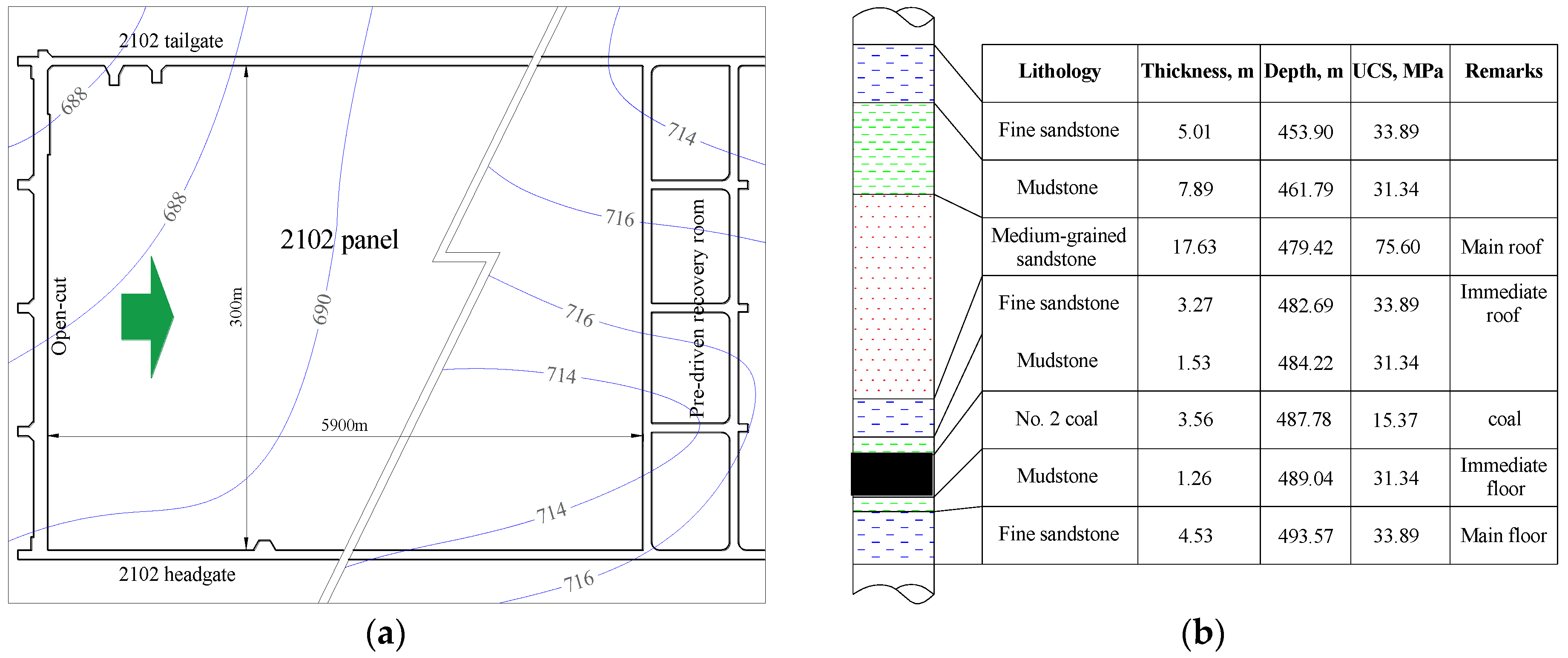
The Balasu coal mine is located in the west of Yulin City. The layout of the 2102 working face is shown in Figure 1a. The width of this face is 300 m, the advancing length is 5900 m, and the 2# coal seam is mined. The average coal thickness is 3.68 m. The longitudinal and transverse inclination of the longwall are 0.4 and 0.8°, respectively, which can be regarded as a horizontal coal seam, and the average buried depth is 480 m, which makes it stable and thick. The average thickness of the immediate roof of the coal seam is 1.53 m, the lithology is mudstone or sandy mudstone, and the main roof is medium-grained sandstone with an average thickness of 17.63 m. The 2# coal roof is mainly hard and difficult to collapse. The roof occurrence characteristics of the 2102 working face are shown in Figure 1b. The average dry compressive strength of the immediate roof and main roof is 100.8 and 75.6 MPa, respectively, and the average saturated compressive strength is 23.0 and 37.1 MPa, respectively. During 2101 mining, the natural caving method is used to manage the roof. If the roof cannot collapse in sufficient time, a large area of suspended roof can easily form, which may cause strong-mine-pressure dynamic disasters such as hurricanes and rock burst.
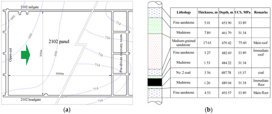
Figure 1.
Layout of longwall panel 2102. (a) Panel layout. (b) Generalized stratigraphy column.
3. Mechanical Analysis of Initial Fracture
The 2102 working face of the Balasu coal mine is the first mining face. Before the initial collapse, it can be regarded as a beam structure with fixed supports at both ends, and there are multi-layer hard and stable sandstones in the upper part of the coal seam. During the mining process, it is not easy to collapse the roof, and there is a risk for a large, suspended roof area, which may lead to strong-mine-pressure dynamic disasters.
According to the method of determining the load of the key layer and its upper part [33], the ultimate caving step of the basic roof can be further calculated. The determination of the key layer and the determination of the upper load layer can be based on the following formula:
where is the load of each layer, kN; (qn)i is the action of the nth layer of rock on the layer of rock, kN; is the elastic modulus of each rock layer, MPa; is the thickness of each rock layer, m; and is the unit weight of each rock layer, kN/m3.
By measuring the physical and mechanical parameters and inputting them into Formula (1), the medium-grained sandstone in the upper 4.8–22.43 m layer of the roof of the 2102 working face can be found to be the basic roof, which determines the first weighting interval of the working face.
Before the initial collapse of the 2102 working face, the upper roof should be a fixed-beam mechanical structure. According to the limit collapse step of the fixed beam [34], it can be seen that
where is the limit collapse step, m; is the tensile strength of the key layer, MPa; is the upper load of the key layer, kN; and h is the thickness of the key stratum.
It can be seen from Equation (2) that under the condition of no fracturing, the first weighting interval of the 2102 first mining face is 77 m.
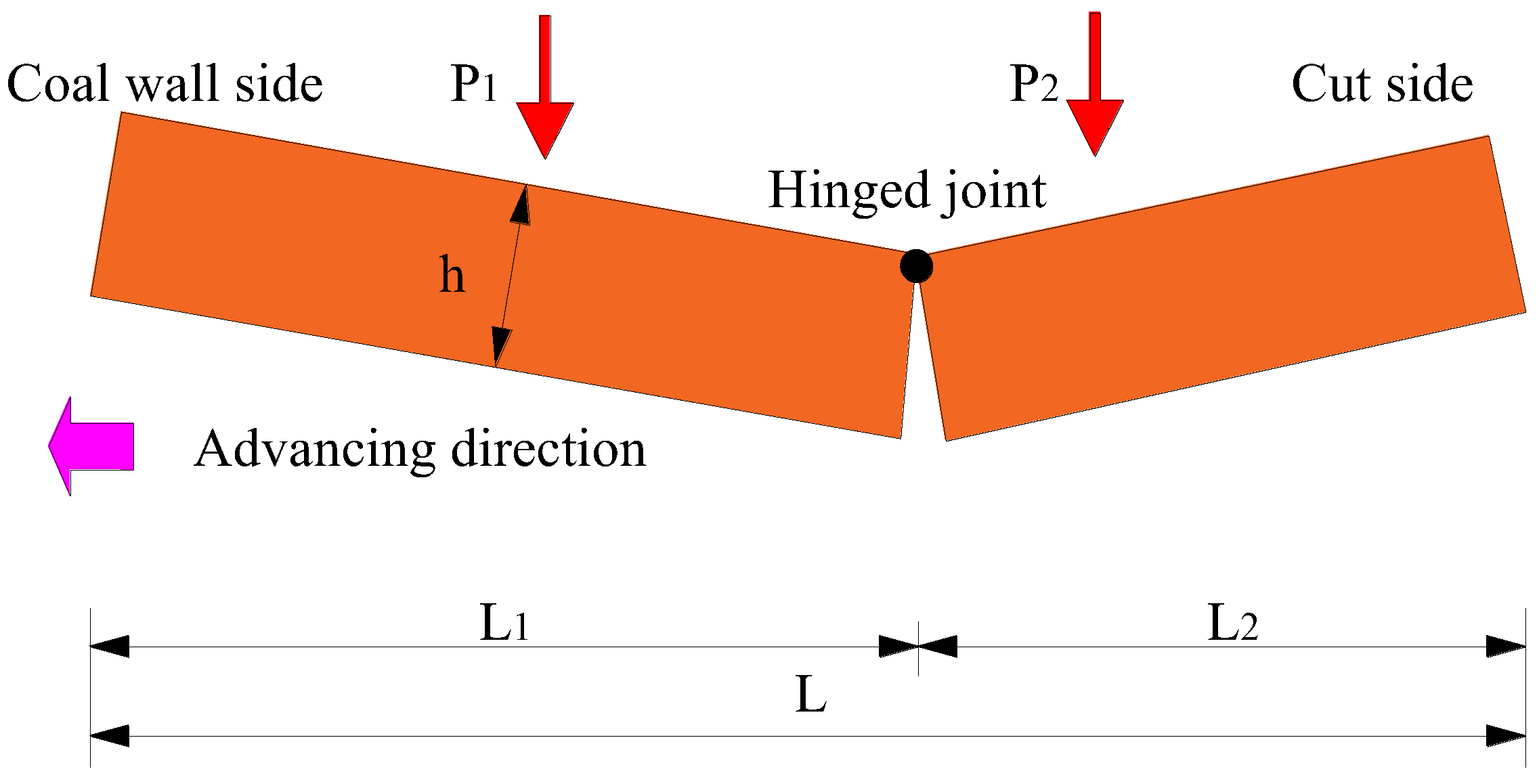
According to the asymmetric three-hinged arch structure [35] of the initial collapse of the roof of the working face, during the advancing process of this face, the damage degree of the roof is different due to the time effect. According to damage mechanics analysis, the initial collapse of the roof of the working face is asymmetric. This collapse is easier to accomplish due to the high degree of damage accumulation near the cut side. The asymmetric three-hinged arch structure of this collapse is shown in Figure 2.

Figure 2.
Asymmetric three-hinged arch structure of initial roof caving.
Considering the accumulation of rock mass excavation damage, the ratio of the length of the rock mass near the working face to the length of the rock mass on the side of the open-off cut is = 1.5, so the easy fracture distance of the roof under unfractured conditions is
where is the ratio of to , and is found to be 1.5 via analysis. Equation (3) shows that the distance of is 30.8 m, so the horizontal projection distance of the effective fracturing section of the hydraulic fracturing borehole should be within the range of 30.8 m in combination with the geological conditions.
Based on the above analysis, in the case of the 2102 working face without hydraulic fracturing roof weakening measures, the mechanical model calculates the first weighting interval to be 77 m, which makes it very easy to cause strong pressure and even dynamic disasters of the working face. The theoretical calculation shows that the reasonable range of hydraulic fracturing in the vertical direction of the working face is from the basic roof of medium-grained sandstone in the 12.26 m layer to the sub-key layer in the 23.43 m layer. The effective fracturing section in the horizontal direction is arranged within 30.8 m from the open-off cut side of the working face.
4. Numerical Simulation of Strain Energy of Hard Roof
4.1. Numerical Model
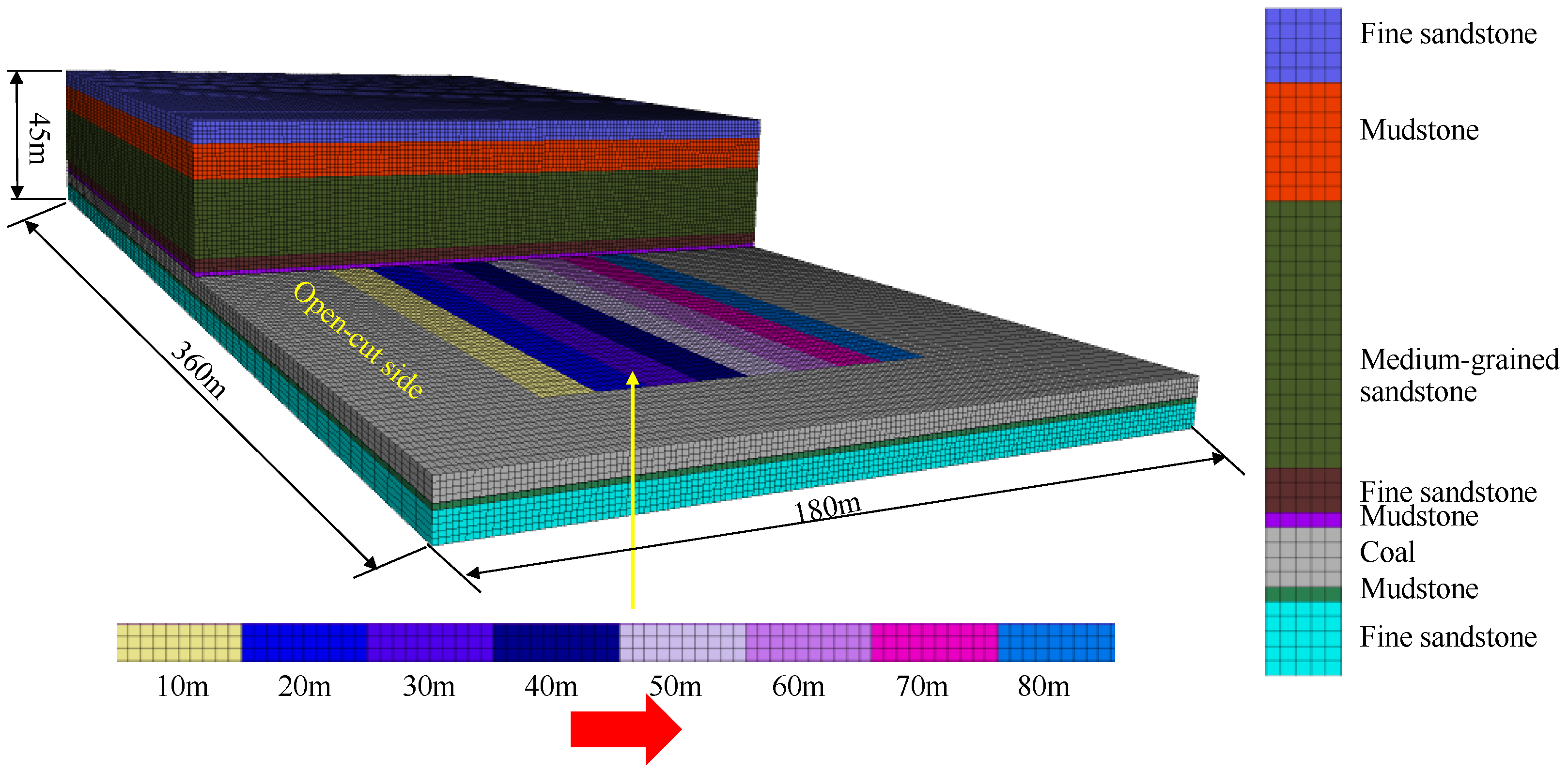
According to the geological conditions, the numerical model is established via FLAC3D, as shown in Figure 3. The length × width × height of the model is 180 m × 360 m × 45 m. The bottom and side displacements of the model are fixed. The Mohr Coulomb criterion has significant advantages in simulating the failure of heterogeneous rock formations. It is a universal geotechnical model widely used in engineering to analyze rock failure. It reflects the failure mechanism of rocks and can effectively simulate the stress and failure state of surrounding rocks [36,37,38]. After parameter calibration through numerical simulation, it is found that the Mohr Coulomb criterion can better match the strength test results in the laboratory. The parameters of the calibrated rock are shown in Table 1. The gob adopts a Null model, which can effectively reflect the empty state of the goaf before the initial collapse of the roof.

Figure 3.
Model overview.

Table 1.
Key rock parameters used in the numerical model.
This simulation analyzes the strain energy of the roof of the goaf at different distances in the 2102 working face, and the simulation is divided into three steps. First: the overall operational balancing of the model under the action of the original rock stress. Second: transport crossheading during tunneling of the 2102 working face and crossheading of the return air. Third: the mining of the 2102 working face every 10 m for a total of 8 times reaching 80 m for the calculation.
The research on the initial mining collapse of the working face roof is mostly simplified to a two-dimensional beam model to study the fracture distance. The energy model used in this study provides a detailed analysis of the energy generation, accumulation, and evolution process of the hard roof above the goaf in the three-dimensional mining space of the working face. It can intuitively determine the location of rock layers that affect mining safety and provide a basis for determining hydraulic fracturing parameters in the later stage.
When performing energy analysis, it is necessary to establish an energy numerical model for calculation. From the perspective of energy, when the rock deforms under the action of external forces, it is assumed that the physical process has no heat exchange with the outside world, and the rock can release elastic strain energy [39], which can be expressed as
where is the elastic modulus; is Poisson‘s ratio; and , , and are the maximum, intermediate, and minimum principal stresses, respectively.
The total strain energy of the element is
where is the strain energy density of the i-th unit body, and is the volume of the i-th unit.
Based on the principle of energy analysis, the calculation program of the elastic strain energy distribution density of coal and rock mass is written in fish language and the calculation program is run in the simulation process.
4.2. Roof Energy Evolution Characteristics
The spatial and temporal distribution characteristics of the elastic strain energy density under different propulsion distances are shown in Figure 4.
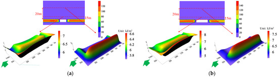
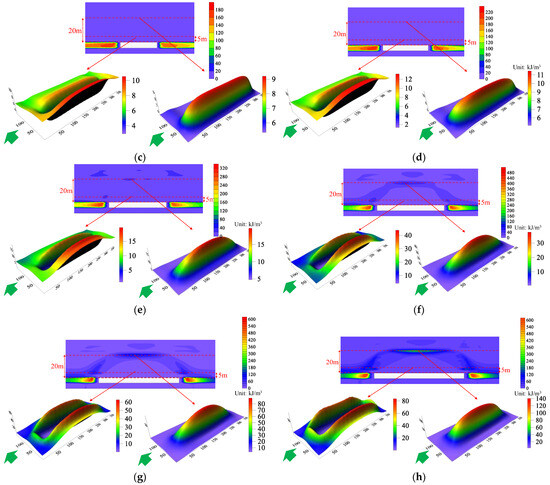
Figure 4.
Temporal and spatial distribution characteristics of elastic strain energy density during mining to (a) 10, (b) 20, (c) 30, (d) 40, (e) 50, (f) 60, (g) 70, and (h) 80 m.
The elastic strain energy of hard roof strata gradually increases with the advance of the working face. When the working face advances 10–40 m, energy accumulation occurs only in the two sides of the working face, and no elastic energy accumulation occurs in the main roof. When the working face advances to 50–60 m, the main roof of the working face begins to bend under the influence of the excavation of the working face, and the accumulation of strain energy occurs in the rock strata affected by the deformation. When the working face advances 70–80 m, the elastic strain energy density of the hard roof strata in front of the coal wall of the working face continues to increase, and the elastic energy accumulation reaches the maximum at 80 m. Finally, an ‘n’-shaped energy gathering area is formed on the roof of the mining area.
In the mining process of the lower part of the main roof (5 m above the goaf), a plastic failure zone is produced in the lower part of the roof of the goaf, and the strain energy accumulated in the lower part of the basic roof is absorbed and released by the coal body in the plastic zone. The strain energy accumulated in the hard roof strata in this area is always low, forming a circular energy accumulation area around the central failure zone. When the working face advances 50, 60, 70, and 80 m, the peak values of elastic strain energy density of hard roof strata are 9.12, 37.41, 63.7, and 82.02 kJ/m3, respectively.
During the mining process, the upper part of the main roof (20 m above the goaf) remains largely undamaged in the middle of the rock layer, and energy accumulates after 50 m, forming an elliptical energy accumulation zone above the center of the goaf. When the working face is advanced by 50, 60, 70, and 80 m, the peak elastic strain energy density of the hard roof rock layer is 9.24, 44.91, 89.21, and 140.54 kJ/m3, respectively.
From the above analysis, it can be seen that as the working face advances to 70 and 80 m, the hard roof begins to bend and deform due to the influence of the excavation of the working face. The strain energy in the rock layer is rapidly accumulated due to the deformation, the peak value of the strain energy gradually increases, and the energy gradient gradually increases. The maximum strain energy of the roof reaches 140.54 kJ/m3. At this moment in time, the working face advances to the first weighting interval. The sudden fracture of the roof will be accompanied by the release of elastic energy, causing roof vibration and inducing rock burst. Therefore, the basic roof should be cut before the first weighting interval to release energy.
5. Technology and Scheme of Hydraulic Fracturing Roof Cutting
According to the analysis results of the fracture and energy release characteristics of the hard roof during initial mining, the comprehensive hydraulic fracturing technology of ‘conventional short drilling + directional long drilling’ is proposed to weaken the roof of the 2102 working face. Through long and short boreholes, regional and staged fracturing construction is carried out to form a three-dimensional fracture network, reduce the strength and integrity of the main roof, and shorten the first weighting interval and weaken the pressure strength.
5.1. Principle of Conventional Straight Hole Hydraulic Fracturing Technology
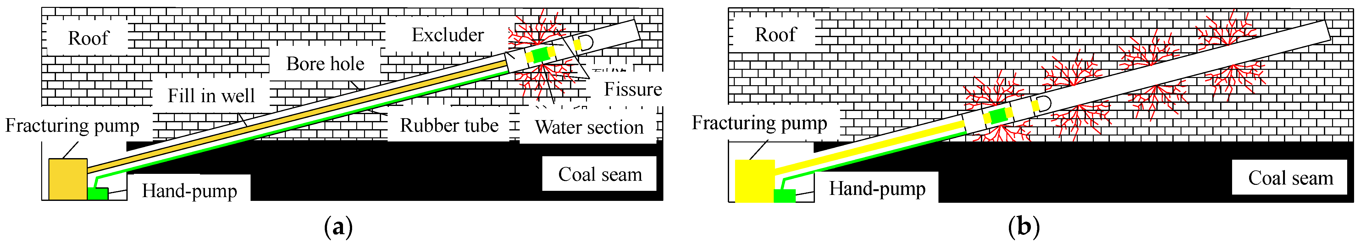
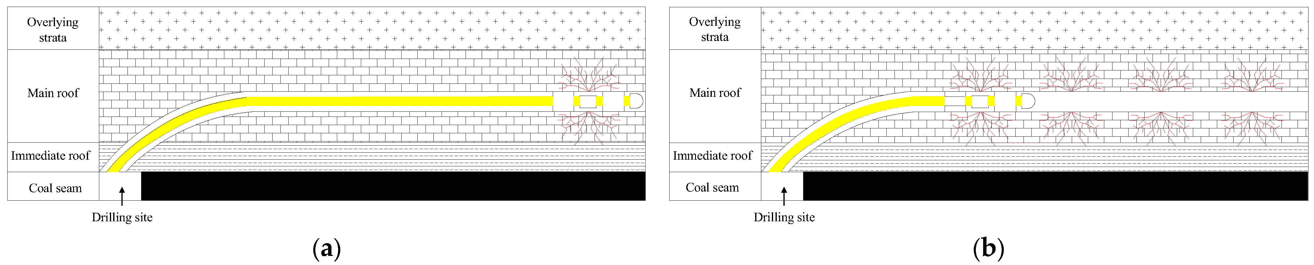
Drilling construction is carried out according to the drilling design. The diameter of the conventional straight hole is generally 65–94 mm, and drilling is often carried out using core and impact drills. After the fracturing work to the design section is completed, the manual pump water injection pressure is used to promote the packer rubber tube to expand and seal the hole. The high-pressure pump is turned on to start the water injection construction. When the water injection pressure is greater than the rock-breaking pressure, the original cracks will be expanded, and a new fracture network will be generated in the target layer, and the first fracturing construction will be completed after the fracturing time is reached. According to the designed fracturing spacing, the fracturing string is withdrawn from the second-stage fracturing section, second-stage fracturing construction continues, and the whole-hole fracturing construction is completed in turn. The principle of conventional straight-hole hydraulic fracturing technology is shown in Figure 5.
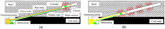
Figure 5.
Principle of conventional straight-hole hydraulic fracturing technology. (a) The first section of construction. (b) Section n of construction.
5.2. Principle of Directional-Hole Hydraulic Fracturing Technology
The diameter of the directional hole is generally 108–113 mm, and directional drilling machines are used for drilling. The continuous water supply of the high-pressure pump promotes the expansion of the sealing device to seal the hole. After the pressure continues to increase to the set pressure, the high-pressure water outlet device is opened to realize the fracturing construction of the designed fracturing section. When the water injection pressure is greater than the fracture pressure of the rock stratum, cracks are generated in this stratum. When the first stage of fracturing construction is completed, the sealing device and the water outlet device are dragged to the design position, and the second stage of fracturing construction is carried out. The fracturing construction of the design and construction section is completed in turn. Three-dimensional continuous cracks are formed in the adjacent fracturing sections, which improves the rock mass structure and reduces the overall strength of the treatment layer [40]. The principle of directional-hole hydraulic fracturing technology is shown in Figure 6.
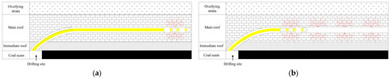
Figure 6.
Principle of directional-hole hydraulic fracturing technology. (a) The first section of construction. (b) Section n of construction.
5.3. Hydraulic Fracturing Roof Cutting Scheme
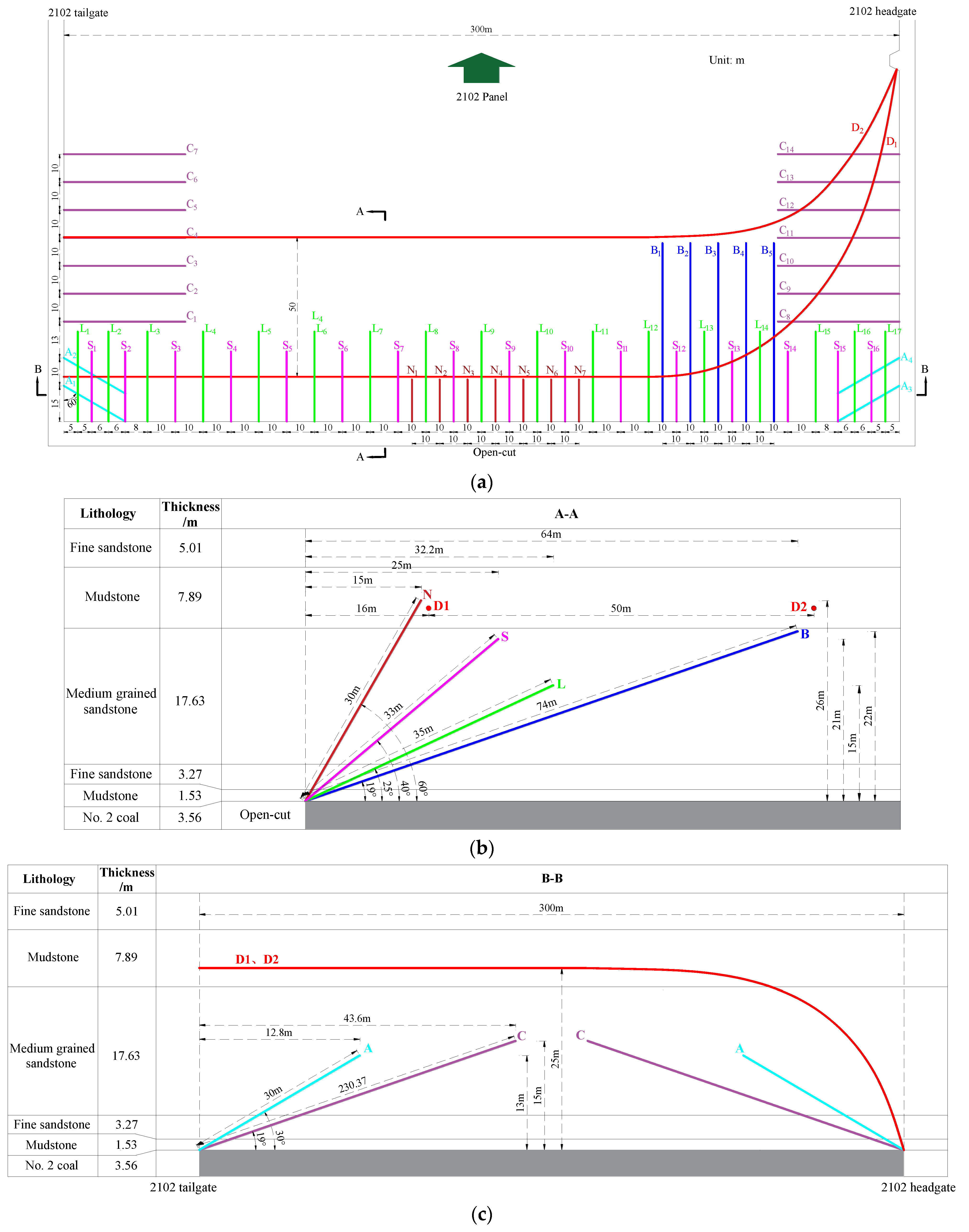
The 2102 open-off cut is constructed via the combination of conventional short-hole fracturing and long-horizontal-hole fracturing. A total of 16 S boreholes are arranged in the open-off cut, and the borehole spacing is 20 m. There are 17 L boreholes with a spacing of 20 m. There are four A holes with a hole spacing of 10 m. Seven N boreholes are drilled with a spacing of 10 m. There are five B boreholes with a spacing of 10 m. Seven C boreholes are arranged in the 2102 auxiliary transport and glue transport troughs, and the borehole spacing is 10 m. One drilling field and two long horizontal holes are arranged in the glue transport crossheading of the 2102 working face, the target horizon is 25 m, and the borehole spacing is 50 m. The drilling construction parameters are shown in Table 2 and Table 3, and the drilling design layout is shown in Figure 7.
Table 2.
Directional-hole construction parameters.
Table 3.
Conventional straight-hole construction parameters.
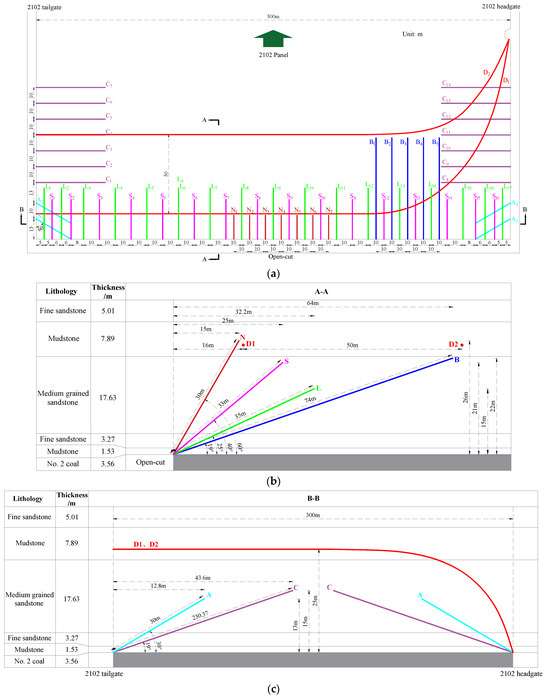
Figure 7.
Hydraulic fracturing roof cutting scheme. (a) Hydraulic fracturing drilling plane diagram. Drilling profile of hydraulic fracturing holes (b) S, L, B, and D, and (c) A, C, and D.
6. Field Effect
6.1. Analysis of High Water Pressure
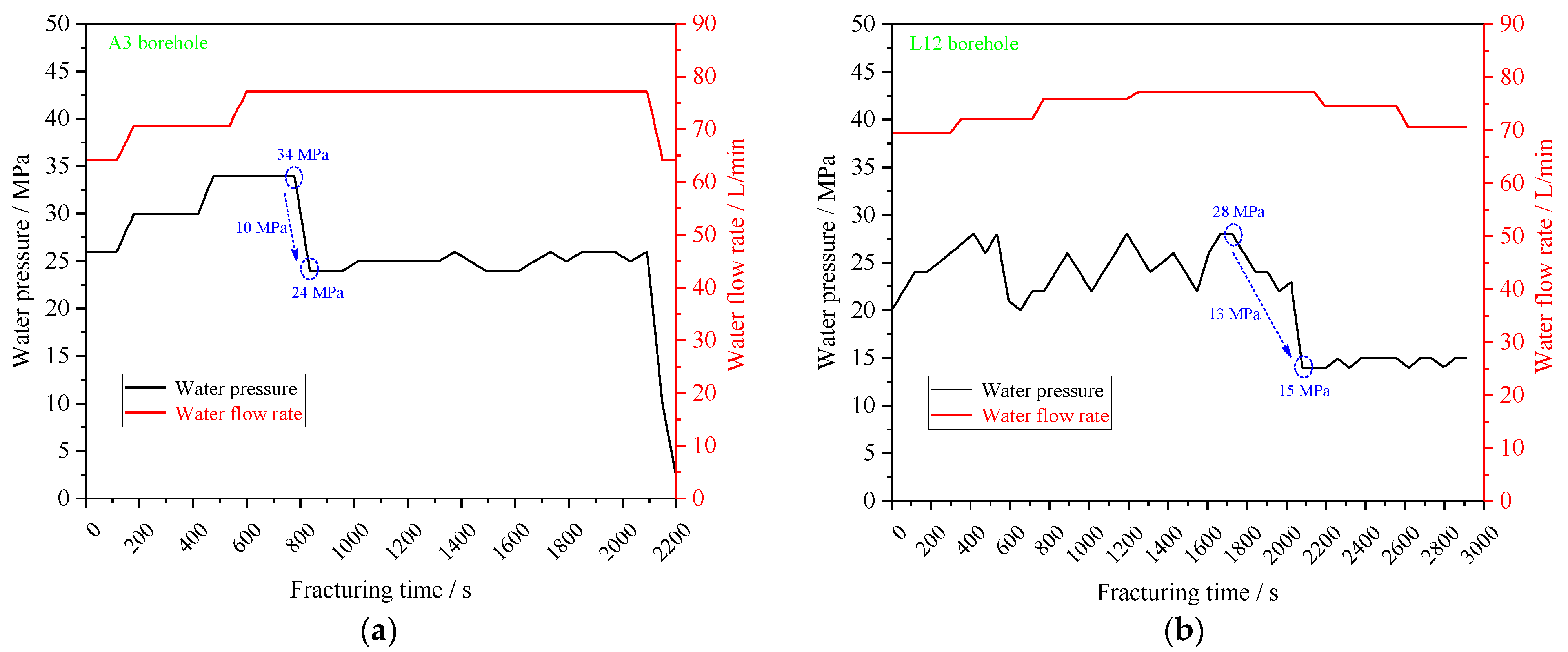
Figure 8 shows the variation curves of high water pressures and water injection flow rates of A3 and L12 holes with time. It can be seen from this figure that the high water pressure of the A3 and L2 holes can reach their peak in 480 and 1700 s, and the maximum pressures are 34 and 28 MPa, respectively. After the peak, the pressure decreases rapidly, and the reduction ranges are 10 and 13 MPa, respectively, indicating that the rock layer is destroyed, and cracks are generated. After fracturing, the water pressure of the two boreholes continues to fluctuate around 25 and 15 MPa. Before the rock layer is fractured, the flow rate of high-pressure water injected into the borehole gradually increases. After the rock layer is fractured, the flow rate of the two boreholes is maintained at 77 L/min. This shows that the continuous high-pressure water injection after the rock layer is fractured forces the expansion of the cracks to continue, which plays a role in weakening the integrity of the rock layer.
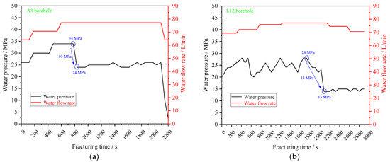
Figure 8.
Curve of hydraulic fracturing water pressure and flow rate vs. time. Boreholes (a) A3 and (b) L12.
6.2. Drilling Peep Analysis
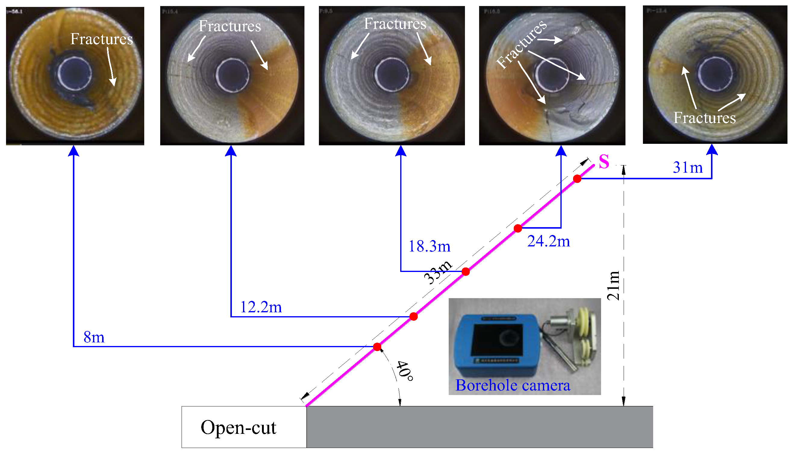
Taking the S6 hole depth of 33 m as an example, the CXK12(A) peeper is used to peep the borehole after fracturing, and the results are shown in Figure 9. It can be seen from this figure that cracks were observed at the depths of 8, 12.2, 18.3, 24.2, and 31 m. The direction of crack propagation can be divided into unilateral expansion in the axial direction of parallel boreholes, bilateral expansion in the axial direction of parallel boreholes, and annular expansion in the axial direction of vertical boreholes. The continuous expansion range of cracks in the extension direction is about 0.5–1.5 m. This shows that the effect of hydraulic fracturing is clear, and cracks are effectively manufactured in the rock layer.

Figure 9.
Drilling peep to detect crack propagation after hydraulic fracturing.
6.3. Analysis of Support Resistance
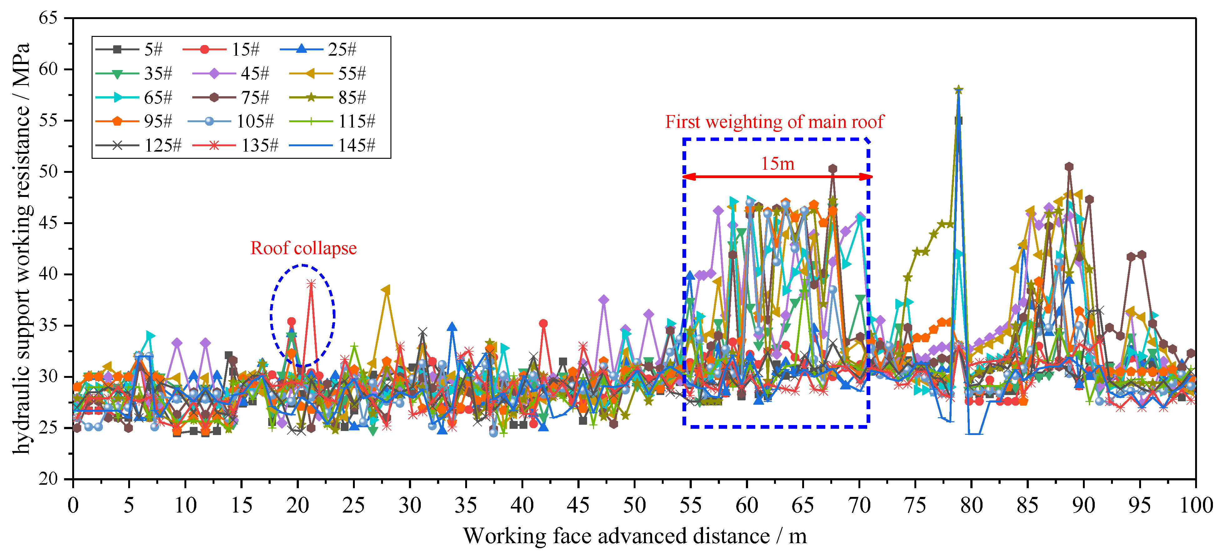
A total of 150 supports are installed in the 2102 working face, and the online monitoring system of hydraulic support resistance is installed. In the initial mining process of the working face, the working resistance of one support is extracted every 10 sets for analysis, and the results are shown in Figure 10. According to the diagram, when the roof does not fall, the support resistance ranges from 25 to 30 MPa. When the working face advances 20 m, the resistance of some supports increases to 40 MPa, indicating that the roof collapses behind the supports (Figure 11). When the working face is advanced to 55 m, the resistance of multiple supports begins to increase significantly, reaching a maximum of 52 MPa, indicating that a large area of the main roof begins to fall, which continues until the end of the pressure at the 70 m position, and the continuous length of the first pressure is 15 m. This shows that, after hydraulic fracturing of the roof, the 2102 working face begins to gradually collapse at 20 m, and a large area of the face begins to collapse at 55 m. After analysis and calculation, the index of load capacity of the roof ‘g’ meets the requirements and can be effectively loaded [41,42]. According to theoretical analysis and numerical simulation, the first weighting interval is about 77 m, and the energy of the roof is largest at this moment in time. After hydraulic fracturing and top cutting for the key layer, the first weighting interval is reduced to 55 m, proving that hydraulic fracturing effectively reduces the first weighting interval and greatly reduces the occurrence rate of strong-dynamic-pressure disasters.
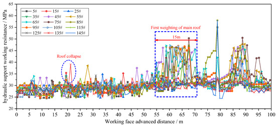
Figure 10.
The working resistance of the support during the mining of the 2102 working face.

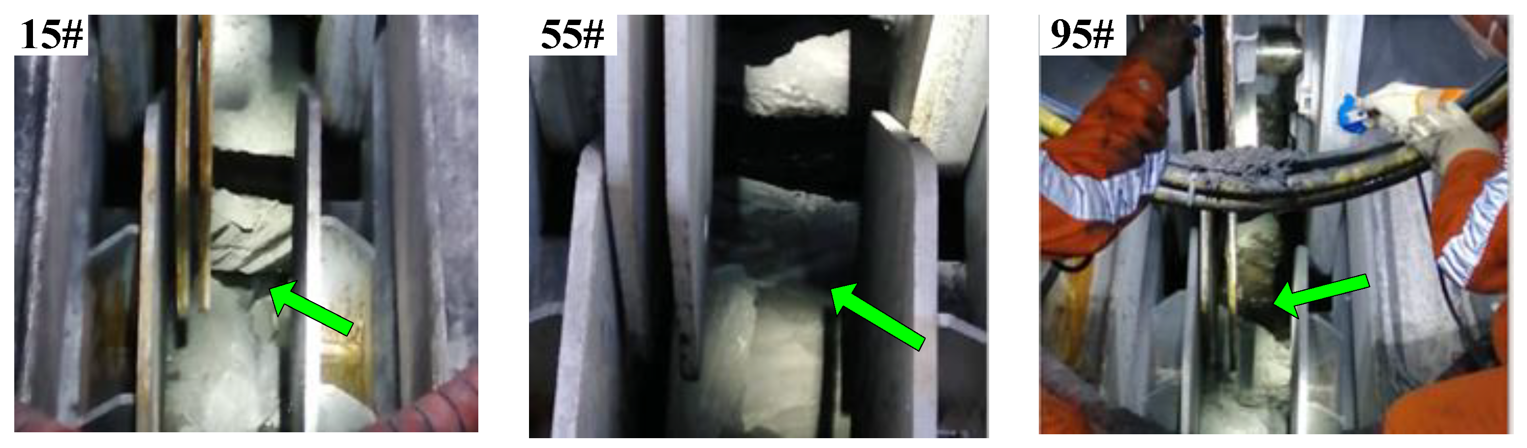
Figure 11.
The roof collapse behind the support of the 2102 working face.
7. Conclusions
Aiming to resolve the issue where rock burst easily occurs during the initial mining of the 2102 working face in the Balasu coal mine, theoretical research, FLAC3D software, and the elastic strain energy fish model are used to analyze the temporal and spatial variation law of roof elastic strain in the mining process. The following conclusions are drawn:
(1) In the case of the 2102 working face without hydraulic fracturing roof-weakening measures, the mechanical model calculates that the first weighting interval is 77 m, easily causing strong pressure and even dynamic disasters in the working face when it falls. The theoretical calculation shows that the main roof is the reasonable range of hydraulic fracturing in the vertical direction of the working face for the medium-grained sandstone in the upper 4.8–22.43 m of the roof of the 2102 working face, and the effective fracturing section in the horizontal direction is arranged within 30.8 m from the cutting side of the working face;
(2) FLAC3D software and the elastic strain energy fish model are used for simulation: as the working face advances to 70 and 80 m, the hard roof begins to bend under the influence of excavation of the working face, and the strain energy in the rock layer is rapidly accumulated under the influence of deformation. The peak value of strain energy gradually increases, and the energy gradient also gradually increases. The maximum strain energy of the roof reaches 140.54 kJ/m3. At this moment in time, the working face advances to the first weighting interval, and the sudden fracture of the roof will be accompanied by the release of elastic energy, resulting in roof vibration and inducing rock burst. Therefore, the main roof should be cut before the first weighting interval to release energy;
(3) According to the temporal and spatial variation law of roof elastic strain in the process of mining, the principle of hydraulic fracturing was proposed, and the test was carried out in the 2102 working face. The field application shows that, after hydraulic fracturing, the continuous high-pressure water injection into the rock layer after fracturing causes the expansion of the cracks to continue and effectively weakens the integrity of the rock layer. The cracks are observed at depths of 8, 12.2, 18.3, 24.2, and 31 m. The 2102 working face begins to gradually collapse at the 20 m position, and a large area of the face begins to collapse at 55 m. There is no support-crushing accident, and hydraulic fracturing effectively reduces the first weighting interval. The research results provide reference for similar narrow-coal-pillar roadway control;
(4) The crack propagation via hydraulic fracturing roof cutting is greatly affected by the stress environment. We can only detect the crack morphology on the surface of the borehole via drilling peeps. When the crack enters the rock mass, the expansion is not accurately detected at present. In the future, extensive in-depth research work should be carried out on the initiation and propagation law of hydraulic fractures in coal and rock mass, which is helpful in forming the crack propagation pattern needed in engineering.
Author Contributions
Conceptualization, C.W. and J.B.; methodology, C.W.; software, C.W. and T.W.; validation, C.W. and J.B.; formal analysis, C.W.; investigation, W.W.; resources, T.W.; data curation, C.W. and T.W.; writing—original draft preparation, J.B.; writing—review and editing, C.W.; visualization, J.B.; supervision, W.W.; project administration, W.W.; funding acquisition, J.B. and W.W. All authors have read and agreed to the published version of the manuscript.
Funding
This research has been supported by the Key projects of the Joint Fund of the National Natural Science Foundation of China (No. U21A20107). the National Natural Science Foundation of China (52204150), the Fundamental Research Program of Shanxi Province (202103021223051), the Youth Foundation of TYUT (2022QN069), the Xinjiang Uygur Autonomous Region Tianchi Introduction Plan (2024XGYTCYC03), and the Key Research and Development Special Tasks of Xinjiang Province (2022B01051).
Data Availability Statement
The data presented in this study are available on request from the corresponding author. The data are not publicly available due to ongoing proprietary research and analysis, which requires the preservation of data integrity and confidentiality for further in-depth studies.
Acknowledgments
We sincerely thank Chunlin Wang, Xiangzhuo Zhao, and Wenzhong Wang for providing us with valuable data support. These data are critical to this study, and without their generous sharing, our work would not have been completed.
Conflicts of Interest
Author Wenda Wu works part-time at the company Xuzhou Coal Mining Group Co. The remaining authors declare that the research was conducted in the absence of any commercial or financial relationships that could be construed as a potential conflict of interest.
References
- Chen, D.; Li, C.; Hua, X.; Lu, X.; Yuan, Y.; Li, C. Rebound mechanism and control of the hard main roof in the deep mining roadway in huainan mining area. Shock Vib. 2021, 2021, 4562365. [Google Scholar] [CrossRef]
- Liu, T.; Lin, B.; Yang, W.; Liu, T.; Xiao, W.; Zha, W. Study of effects of hard thick roof on gas migration and field experiment of roof artificially guided pre-splitting for efficient gas control. Nat. Resour. Res. 2020, 29, 1819–1841. [Google Scholar] [CrossRef]
- Yang, S.; Hua, X.; Yang, P.; Liu, X. Determination and engineering practice of unsupported roof distance for rapid excavation of roadway with thick and hard basic roof. Geotech. Geol. Eng. 2021, 39, 5161–5172. [Google Scholar] [CrossRef]
- Ji, Z.; Li, J.; Zhang, X.; Song, Z. A quantitative assessment method for the correlation between rock mass basic quality and Protodyakonov coefficient. Front. Earth Sci. 2023, 11, 1249866. [Google Scholar] [CrossRef]
- Liu, C.; Li, H.; Mitri, H. Effect of strata conditions on shield pressure and surface subsidence at a longwall top coal caving working face. Rock Mech Rock Eng 2019, 52, 1523–1537. [Google Scholar] [CrossRef]
- He, H.; Dou, L.; Fan, J.; Du, T.; Sun, X. Deep-hole directional fracturing of thick hard roof for rockburst prevention. Tunn. Undergr. Space Technol. 2012, 32, 34–43. [Google Scholar] [CrossRef]
- Zhang, X.; Hu, J.; Xue, H.; Mao, W.; Gao, Y.; Yang, J.; He, M. Innovative approach based on roof cutting by energy-gathering blasting for protecting roadways in coal mines. Tunn. Undergr. Space Technol. 2020, 99, 103387. [Google Scholar] [CrossRef]
- Huang, Q. Stuuctural analysis of main roof stability during first weighting in longwall face. Chin. J. Rock Me-Chanics Eng. 1998, 17, 521–526. [Google Scholar]
- Xu, L.; Lu, K.; Pan, Y.; Qin, Z. Study on rock burst characteristics of coal mine roadway in China. Energy Sources Part A Recovery Util. Environ. Eff. 2022, 44, 3016–3035. [Google Scholar] [CrossRef]
- Liu, X.; Bian, J.; Liu, C. Determination of energy release Parameters of free side roof fracturing based on surrounding rock control of dynamic pressure roadway. J. Min. Strat. Control. Eng. 2021, 1–10. [Google Scholar] [CrossRef]
- Ma, Z. Numerical Simulation Study on Evolution Characteristics of Stress Field and Fracture Field after Hard Roof Pre-Cracking and Weakening. Mine Eng. 2020, 8, 380–389. [Google Scholar]
- Liu, H.; Dai, J.; Jiang, J.; Wang, P.; Yang, J. Analysis of overburden structure and pressure-relief effect of hard roof blasting and cutting. Adv. Civ. Eng. 2019, 2019, 1354652. [Google Scholar] [CrossRef]
- Xue, J.; Ma, Q.; Du, X.; Zhan, K.; Sun, B. Numerical simulation and control of a rockburst induced by main roof fracture in a deep coal seam. Energy Sources Part A Recovery Util. Environ. Eff. 2020, 1–17. [Google Scholar] [CrossRef]
- Liu, B.; Wang, S. Dynamic load impact response characteristics of the hard roof of shallow buried thick coal seam. In Advances in Measurement Technology and Disaster Prevention; CRC Press: Boca Raton, FL, USA, 2024; pp. 491–498. [Google Scholar]
- Zheng, Z.; Xu, Y.; Li, D.; Dong, J. Numerical analysis and experimental study of hard roofs in fully mechanized mining faces under sleeve fracturing. Minerals 2015, 5, 758–777. [Google Scholar] [CrossRef]
- Wang, H.; Deng, D.; Shi, R.; Yang, G.; Xu, S.; Jiang, Y. Investigation on the Movement and Fracture Characteristics of an Extra-Thick Hard Roof during Longwall Panel Extraction in the Yima Mining Area, China. Geofluids 2021, 2021, 4092242. [Google Scholar] [CrossRef]
- Li, M.; Zhou, N.; Zhang, J.; Liu, Z. Numerical modelling of mechanical behavior of coal mining hard roofs in different backfill ratios: A case study. Energies 2017, 10, 1005. [Google Scholar] [CrossRef]
- Xie, S.; Wu, Y.; Guo, F.; Zou, H.; Chen, D.; Zhang, X.; Ma, X.; Liu, R.; Wu, C. Application of pre-Splitting and roof-cutting control technology in coal mining: A review of technology. Energies 2022, 15, 6489. [Google Scholar] [CrossRef]
- Chen, J.; Qu, Z.; Zhou, L.; Su, X. Numerical study on the hydraulic fracturing pattern in the hard roof in response to mining-induced stress. Minerals 2023, 13, 308. [Google Scholar] [CrossRef]
- Yang, X.; Liu, C.; Ji, Y.; Zhang, X.; Wang, S. Research on roof cutting and pressure releasing technology of directional fracture blasting in dynamic pressure roadway. Geotech. Geol. Eng. 2019, 37, 1555–1567. [Google Scholar] [CrossRef]
- Shao, L.Y.; Huang, B.X.; Zhao, X.L.; Chen, S.L. Hydraulic fracturing method for relieving stress concentration in remaining coal pillar in overlying goaf. Energy Sci. Eng. 2024, 12, 1518–1530. [Google Scholar] [CrossRef]
- Cao, X.; Wu, S.S.; He, Q.Y. Investigation into Influences of Hydraulic Fracturing for Hard Rock Weakening in Underground Mines. Appl. Sci. 2024, 14, 1948. [Google Scholar] [CrossRef]
- Qiu, R.; Zhang, G.; Zheng, X.; Luo, S.; Chen, H.; Zhao, J. Stress transfer law in laboratory hydraulic fracturing experiments. Scientific Reports. Rock Mech. Rock Eng. 2024, 14, 17287. [Google Scholar]
- Powlay, B.; Karakus, M.; Amrouch, K.; Chester, C. Effects of Notches on Breakdown Pressures and Fracture Evolution in Hydraulic Fracturing. Rock Mech. Rock Eng. 2024, 1–14. [Google Scholar] [CrossRef]
- Zhao, K.K. Three-Dimensional Propagation of Hydraulic Fracture from Regional Fracturing in Hard Roof. Ph.D. Thesis, China Coal Research Institute, Beijing, China, 2021. [Google Scholar]
- Zhang, F.; Wang, X.; Bai, J.; Wu, W.; Wu, B.; Wang, G. Fixed-length roof cutting with vertical hydraulic fracture based on the stress shadow effect: A case study. Int. J. Min. Sci. Technol. 2022, 32, 295–308. [Google Scholar] [CrossRef]
- Lecampion, B.; Bunger, A.; Zhang, X. Numerical methods for hydraulic fracture propagation: A review of recent trends. J. Nat. Gas Sci. Eng. 2018, 49, 66–83. [Google Scholar] [CrossRef]
- Xia, B.; Zhang, X.; Yu, B.; Jia, J. Weakening effects of hydraulic fracture in hard roof under the influence of stress arch. Int. J. Min. Sci. Technol. 2018, 28, 951–958. [Google Scholar] [CrossRef]
- Huang, B.; Liu, J.; Zhang, Q. The reasonable breaking location of overhanging hard roof for directional hydraulic fracturing to control strong strata behaviors of gob-side entry. Int. J. Rock Mech. Min. Sci. 2018, 103, 1–11. [Google Scholar] [CrossRef]
- Zhang, F.; Wang, X.; Bai, J.; Wu, B.; Wang, G.; Li, J.; Chen, D. Study on hydraulic fracture propagation in hard roof under abutment pressure. Rock Mech. Rock Eng. 2022, 55, 6321–6338. [Google Scholar] [CrossRef]
- Kang, H.P. Seventy years development and prospects of strata control technologies for coal mine roadways in China. Chin. J. Rock Mech. Eng 2021, 40, 1–30. [Google Scholar]
- Wu, W.D. Failure Characteristics and Cooperative Control Strategies for Gob-Side Entry Driving near an Advancing Working Face: A Case Study. Processes 2024, 12, 1398. [Google Scholar] [CrossRef]
- Qian, M.; Miao, X.; Xu, J. Theoretical study of key stratum in ground control. Mei Tan Hsueh Pao (J. China Coal Soc.) 1996, 21, 225–230. [Google Scholar]
- Zhang, J.; Miao, X.; Huang, Y.; Li, M. Fracture mechanics model of fully mechanized top coal caving of shallow coal seams and its application. Int. J. Min. Sci. Technol. 2014, 24, 349–352. [Google Scholar] [CrossRef]
- Yang, B.; Lu, X. The Primary Breaking Pattern of Main Roof above the First Working Face Based on Main Bending Moment. 2020. Available online: https://www.researchsquare.com/article/rs-127355/v1 (accessed on 28 July 2024).
- Zhu, D.F.; Yu, B.B.; Wang, D.Y.; Zhang, Y.J. Fusion of finite element and machine learning methods to predict rock shear strength parameters. J. Geophys. Eng 2024, 21, gxae064. [Google Scholar] [CrossRef]
- Singh, G.S.P.; Singh, U.K.; Murthy, V.M.S.R. Applications of numerical modelling for strata control in mines. Geotech. Geol. Eng. 2010, 28, 513–524. [Google Scholar] [CrossRef]
- Shabanimashcool, M.; Li, C.C. Numerical modelling of longwall mining and stability analysis of the gates in a coal mine. Int. J. Rock Mech. Min. Sci. 2012, 51, 24–34. [Google Scholar] [CrossRef]
- Hamiel, Y.; Lyakhovsky, V.; Ben-Zion, Y. The elastic strain energy of damaged solids with applications to non-linear deformation of crystalline rocks. Pure Appl. Geophys. 2011, 168, 2199–2210. [Google Scholar] [CrossRef]
- Kaige, Z.H.E.N.G.; Junzhe, Y.A.N.G.; Bingang, L.I.; Yanjun, L.I.; Nan, D.A.I.; Huan, Y.A.N.G. Collapse filling-based technology of weakening and danger-solving by staged fracturing in hard roof. Coal Geol. Explor. 2021, 49, 77–87. [Google Scholar]
- Herezy, Ł.; Janik, D.; Skrzypkowski, K. Powered roof support–rock strata interactions on the example of an automated coal plough system. Stud. Geotech. Et Mech. 2018, 40, 46–55. [Google Scholar] [CrossRef]
- Skrzypkowski, K.; Korzeniowski, W.; Duc, T.N. Choice of powered roof support FAZOS-15/31-POz for Vang Danh hard coal mine. Inżynieria Miner. 2019, 21, 175–182. [Google Scholar] [CrossRef]


Disclaimer/Publisher’s Note: The statements, opinions and data contained in all publications are solely those of the individual author(s) and contributor(s) and not of MDPI and/or the editor(s). MDPI and/or the editor(s) disclaim responsibility for any injury to people or property resulting from any ideas, methods, instructions or products referred to in the content. |
© 2024 by the authors. Licensee MDPI, Basel, Switzerland. This article is an open access article distributed under the terms and conditions of the Creative Commons Attribution (CC BY) license (https://creativecommons.org/licenses/by/4.0/).