Article

Stability Analysis of Surrounding Rock and Initial Support of Tunnel Undercrossing Multi-Situational Goafs: A Reference of Construction Guidance

1
School of Civil Engineering, Henan Polytechnic University, Jiaozuo 454003, China
2
China Railway 15th Bureau Group Co., Ltd., Shanghai 200070, China
*
Author to whom correspondence should be addressed.
Appl. Sci. 2024, 14(16), 7412; https://doi.org/10.3390/app14167412 (registering DOI)
Submission received: 19 July 2024 / Revised: 18 August 2024 / Accepted: 19 August 2024 / Published: 22 August 2024

Abstract

:
To ensure the construction and operational safety of tunnel undercrossing multi-situational goafs, the Huaying Mountain High-Speed Rail Tunnel, a critical section of the Xi’an-Chongqing High-Speed Railway, was taken as a case study. Based on a three-dimensional finite difference numerical simulation platform, twelve situations were established to analyze the effects of three factors: distance, scale, and angle. The stability analysis was conducted by examining the displacement and deformation characteristics of the surrounding rock, stress changes, and axial forces of the initial support for each situation. The results show that in tunnel undercrossing multi-situational goafs, the vertical deformation, horizontal convergence of the surrounding rock, and the maximum axial force of initial support are all affected. Within a certain range, changes in distance significantly impact subsidence and settlement deformation of the surrounding rock. However, as the distance increases, the horizontal and vertical displacements of the tunnel and the axial force of the initial support tend to decrease. Conversely, the scale and angle of the goaf have an opposite effect on the surrounding rock: as the scale and angle increase, the stability of the surrounding rock deteriorates. In this case study, when the distance exceeds 1.13 times the tunnel span, the influence of the goaf on the stability of the surrounding rock gradually decreases. When the angle exceeds 45°, vertical displacement decreases, and the increasing trend of horizontal displacement gradually diminishes. The conclusions of this paper can provide guidance for designing reinforcement schemes for tunnels crossing through multi-situational goafs. The findings provide valuable insights and guidance for similar engineering projects.

1. Introduction

With the rapid development of China’s economy, the demand for transportation has increased dramatically. Consequently, infrastructure construction represented by expressways and high-speed railways has developed rapidly, and the proportion of tunnels in such projects has become increasingly significant. The southwest region, as an important coal resource gathering area and major production region in southern China, has many goafs formed by long-term mining activities. During the construction of the tunnel, it is easy to be affected by various factors around the tunnel, which will cause the deformation and displacement of the tunnel [1,2,3,4]. The impact of this disturbance is more serious when crossing the goaf. During the process of tunnels crossing through coal seam goafs, disturbances to the strata will occur, disrupting the original equilibrium state of the goaf, leading to activation and collapse of the goaf rock layers. This poses threats to tunnel construction and operation, resulting in uneven settlement of the tunnel, significant deformation of the surrounding rock, intrusion of lining structures beyond the tunnel’s architectural limits, and cracking of the lining structure [5,6,7,8,9,10,11]. For example, the Yudushan Tunnel of the Yanqing-Chongli Expressway, a major traffic project for the Beijing Winter Olympics, encounters a goaf at its entrance. The goaf lies above the tunnel along the slope body, and tunnel excavation disrupts the mechanical balance of the goaf, potentially causing large-scale landslides that directly endanger the tunnel itself and the construction and operational safety of the bridge outside the tunnel entrance [12]. Similarly, during the construction of the Hejiadi Tunnel’s exit section on the Shanghai-Kunming Railway Passenger Line, the influence of the goaf led to deformation and cracking of the secondary lining and the formation of long, thorough surface cracks, severely impacting the normal construction and operation of the tunnel [13]. The Taoping Tunnel has experienced continuous issues such as lining cracking and bulging due to goafs since its construction. Over a period of more than 50 consecutive days, the maximum longitudinal crack at the vault extended up to 8.1 m, with a maximum width increase of 32 mm and multiple instances of lining detachment and spalling, severely threatening traffic safety [14].
In order to reduce the influence of the goaf on the stability of the surrounding rock of the tunnel, one of the methods of minimizing the deformation of overlying workings is filling the workings with rock backfill, which has good compressibility [15,16]. Another method to ensure the stable excavation and operation of the tunnel is to carry out advanced reinforcement during tunnel excavation. This scheme usually uses bolt and pipe shed combined with corresponding position grouting to achieve the effect of reinforcement of the corresponding position of the tunnel [17,18,19,20,21,22], and some supporting devices are also used to support the tunnel. In order to effectively guide the reinforcement of the goaf, it is necessary to design a targeted reinforcement scheme according to the location and characteristics of different goafs, which will save money and construction time. The above method requires the influence law of different goafs on the surrounding rock of the tunnel as the premise guidance. Therefore, given the high-risk construction and operational safety challenges posed by tunnels near goafs, it is of great significance to explore the deformation characteristics of the surrounding rock and the stress conditions of the initial support in tunnels undercrossing multi-situational goafs and to analyze the factors affecting the stability of these tunnels.
In recent years, many scholars have conducted extensive research on the impact of goafs on the stability of tunnel surrounding rocks and initial support. With the enhancement of computer computational capabilities, numerical analysis methods have been widely applied to the stability issues of surrounding rocks. Starfield et al. [23] provide inspiration for rock mechanics modeling. Grenon et al. [24] developed a model that can consider the finite length of nodes and the influence of random nodes, which opens up the way for subsequent numerical simulation. Razak et al. [25] used discrete element numerical simulation software to analyze the stability of the packing in the filling mining field. Choi et al. [26] discussed the relationship between abandoned underground coal mines and coal mining subsidence in underground goaf, and they analyzed the geological characteristics and coal seam distribution around the goaf. Samir et al. [27] used the finite element simulation software to simulate the tunnel excavation and support, and they proposed a new algorithm in the simulation. Sun et al. [28] analyzed the safe distance and energy evolution mechanism of deep tunnels crossing sideways through goafs and concluded that the optimal safe distance between the tunnel and the goaf is approximately equal to the tunnel span. Chen et al. [29] established a numerical calculation model for tunnel construction under goafs, studying the distribution of plastic zones, stress characteristics, and deformation patterns of the surrounding rock. They found that goafs have the greatest impact on the surrounding rock of tunnels located directly beneath them. Li et al. [30] developed a similar simulation test system for tunnels crossing under goafs and, combined with numerical simulation analysis methods, analyzed the fracture initiation and evolution patterns of surrounding rocks during tunnel construction under goafs. Huang et al. [31] conducted continuous monitoring of tunnel surrounding rock deformation and arch frame internal forces at typical sections, comparing and analyzing the deformation and stress patterns of high-speed railway tunnel surrounding rocks at different construction stages and examining the deformation patterns of surrounding rocks in high-speed railway tunnels crossing through goafs. Li et al. [32] simulated the distribution characteristics and evolution process of vertical stress and failure zones around the roadway affected by mining activities in FLAC3D. SIKORA et al. [33] used the FLAC3D program to evaluate the impact of mining activities on mining topographic deformation. Jiang [34] analyzed the failure of the aquiclude in the coal seam floor in the established numerical model and found the cause of the water inrush channel on the floor of the goaf. From a practical condition of the site, He et al. [35] analyzed the shape evolution of the goaf by using the numerical simulation software and established the prediction model of the shape evolution of the goaf and the surface subsidence. Through a variety of methods, Lu et al. [36] studied the stability of the foundation in the goaf area. Zhang et al. [37] obtained the internal structure of the goaf area by high-precision instruments and used Plaxis to study the causes of surrounding rock damage caused by the goaf area. He et al. [38] studied the stability and control of surrounding rock in a large section mining space under a goaf via numerical simulation and other methods. With numerical simulation, Cai et al. [39] studied the stability of a goaf using a geological model test to judge the safety of the tunnel.
The aforementioned research primarily focuses on the mechanical behavior during goaf tunnel construction, deformation instability mechanisms, and the stability of surrounding rock. However, due to the complex and variable situations at construction sites during tunnel excavation, there are regions where numerous privately operated illegal coal mines have left abandoned goafs. Undercrossing multi-situational goafs will have different effects on the surrounding rock and initial support in the tunnel.
Therefore, this study plans to use the Huaying Mountain High-Speed Railway Tunnel as a project basis to investigate the deformation characteristics of surrounding rocks and stress conditions of initial support when undercrossing multi-situational goafs. This research aims to further ensure the safety of tunnel construction in a goaf area. The study employs finite difference methods to analyze the stress and displacement characteristics of surrounding rocks and the axial force characteristics of support structures under 12 goaf situations, varying in distance, scale, and angle. The findings on the displacement and stress variation of tunnel surrounding rocks and the stress conditions of initial support can provide theoretical analysis support for investigating the different impacts of goaf locations, sizes, and angles on the tunnel when crossing goafs. These results can also serve as a reference for designing reinforcement plans for tunnels affected by different goaf conditions and help assess the extent of tunnel deformation due to specific goaf distances, sizes, and angles. This effort is intended to provide valuable insights for similar engineering projects.

2. Project Profile

The entrance of the Huaying Mountain High-Speed Rail Tunnel is located in Qingshui Town, Dazhu County, Dazhou City, Sichuan Province, in the section DK314+990, and at the exit in Langya Town, Qu County, Dazhou City, Sichuan Province, in the section DK327+140. The length of the tunnel is 120 m, with a maximum burial depth of approximately 600 m. It traverses the coal-bearing strata of the Upper Triassic Xujiahe Formation (T3xj), which are located at steep slopes at both the entrance and exit ends of the tunnel. The tunnel line crosses the Eastern Sichuan parallel ridge-valley region, which is predominantly composed of the Jurassic and Cretaceous “Eastern Sichuan Red Beds” mudstone and sandstone. These strata are extensively distributed in the wide, gentle synclinal hilly areas, occupying more than 90% of the region. On both sides of the Huaying Mountain Tunnel are isolated anticlines, exposing the Triassic Xujiahe Formation sandstone and coal-bearing strata, with the core areas consisting of soluble rocks from the Permian and Triassic periods. Due to geological tectonic actions, this region has formed steep, high-altitude “mountain-gorge” landscapes with significant elevation differences. The central part of the tunnel passes through several karst valleys and sinkholes, while the entrance and exit sections have relatively gentle slopes, transitioning from hilly to low mountainous terrain. The terrain gradually becomes more undulating with dense ravines. The tunnel traverses several trenches with thick overburden, resulting in shallow tunnel burial depths. Local terrain-induced bias loading poses significant construction challenges at the tunnel entrances and exits.
The tunnel crosses two mining subsidence areas formed by coal mining activities in the sections from DK318+130 to DK318+230 and from D1K325+970 to D1K326+030. These sections are prone to roof collapses and geological hazards, such as old mine water accumulation. Based on drilling data combined with preliminary information and measurements, near the entrance section, the No. 4, No. 3, and No. 2 coal seams were mined out above +467 m, while the No. 1 coal seam was mined out above +425 m. The tunnel undercrossing these goafs runs from DK318+130 to DK318+230, with the shoulder elevation at approximately +400 m and the lowest elevation of the goaf at +425 m. The goaf is at approximately 25 m minimum distance from the track surface and affects the tunnel project. The location relationship between the tunnel and the goaf is shown in Figure 1.

3. Numerical Calculation of Surrounding Rock and Initial Support Deformation Law of Tunnel Undercrossing Multi-Situational Goaf

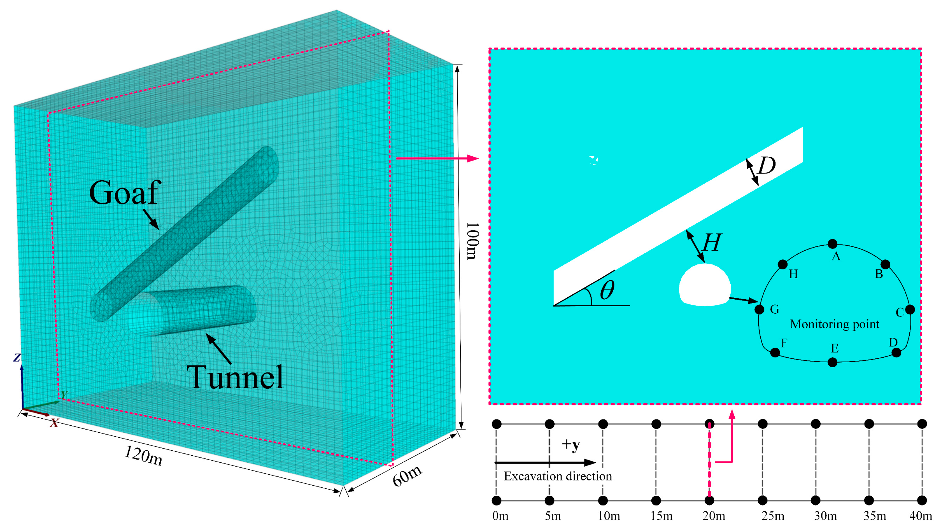
3.1. Numerical Model and Boundary Conditions

The distribution relationships between the existing goaf and the tunnel are mainly divided into parallel, oblique, and orthogonal, and the influence of different goaf distribution forms on the mechanical characteristic of the tunnel is different, considering that the Huaying Mountain High-Speed Rail Tunnel and the goaf have a certain angle, and these goafs are located above the tunnel. Therefore, in this paper, the relationship between the location of the goaf and the tunnel is simplified, as shown in Figure 2. Based on the distribution characteristics of the surrounding rock and the goaf in the Huaying Mountain High-Speed Rail Tunnel segment, a 3D numerical model of the tunnel was constructed using FLAC3D (Version 6.0) numerical simulation software, according to the actual dimensions of the Huaying Mountain High-Speed Rail Tunnel project. The tunnel span is 13.23 m, the height is 12.31 m, and the depth is 60 m. With the Saint-Venant principle, the numerical model’s boundary conditions were determined, taking into full consideration the actual engineering cross-section of the tunnel and eliminating the boundary effects generated during numerical simulation. The dimensions of the 3D numerical model in the x, y, and z directions were set as 120 m, 60 m, and 100 m, respectively (Figure 2). The monitoring points at the tunnel cross-section are labeled A-H (as shown in Figure 2). The goaf section surrounding rock of the tunnel was treated as isotropic elastoplastic material using the Mohr–Coulomb theory. The upper boundary of the model was set as a free boundary; the bottom was fixed; and the remaining boundaries were subjected to normal displacement constraints. The surrounding rock is affected by its own gravity, and the unit weight of the surrounding rock is γ = 24 kN/m3. The lateral pressure coefficient K = 0.5 is set in the scheme, that is, the vertical stress is equal to the horizontal stress in the x direction, and the y direction stress is half of the x direction stress.

3.2. Material Parameter Selection and Scheme Setting

The model first determines the excavation face dimensions based on the tunnel size at the construction site. In Midas GTX NS, a model with dimensions of 120 m, 60 m, and 100 m in the x, y, and z directions, respectively, is created and meshed. The model is then imported into FLAC3D (Version 6.0) software, where the rock mass parameters are assigned using command scripts. The rock mass uses the Mohr–Coulomb criterion, with the following parameters: Young’s modulus E = 2 GPa, Poisson’s ratio μ = 0.3, bulk modulus = 1.67 GPa, shear modulus = 0.77 GPa, friction = 30°, cohesion = 0.2 MPa, and density = 2250 kg/m3. Considering the actual excavation conditions of the Huaying Mountain High-Speed Rail Tunnel, the tunnel excavation employs full-face excavation using cyclic mechanical methods. The advance per cycle is 2 m, and the total length of tunnel excavation is 40 m. The FISH language is used to set up excavation command scripts. During tunnel excavation, void commands are used to remove elements to simulate the excavation of rock. Immediately after excavation, the initial support measures are implemented. The initial support thickness is 23 cm. The initial support is made of concrete material, simulated using shell elements. The shell elements are set as isotropic, with a Young’s modulus E = 25 GPa, Poisson’s ratio = 0.22, density = 2500 kg/m3. Based on geological survey data and on-site material, the numerical model parameters of the Huaying Mountain High-Speed Rail Tunnel are shown in Table 1. To conduct accurate numerical simulation studies, the goaf in Huaying Mountain was simplified into a cylindrical shape, neglecting the influence of roof collapse in the goaf on the tunnel floor. The center cross-section of the goaf is located 20 m from the entrance of the excavation section, with a longitudinal length of 80 m and a circular cavity with a diameter of D. The goaf is inclined horizontally to the tunnel at an angle θ, with a distance H between the goaf and the tunnel. The interior of the goaf cavity is unfilled. The spatial relationship between the goaf and the tunnel is depicted in Figure 2.
To analyze the impact patterns of different distances, scales, and angles of the goaf relative to the tunnel on the stability of surrounding rock, simulation scenarios were designed, as outlined in Table 2. Situation I maintains a constant scale and angle of the goaf, examining different distances (H values of 5 m, 10 m, 15 m, and 20 m), evaluating the displacement, stress, and initial support axial forces of the surrounding rock. Situation II maintains constant distance and angle, investigating different scales of the goaf (D values of 5 m, 7.5 m, 10 m, and 12.5 m), analyzing the displacement, stress, and initial support axial forces of the surrounding rock. Situation III maintains constant distance and scale of the goaf, exploring different angles (θ values of 15°, 30°, 45°, and 60°), examining the displacement, stress, and initial support axial forces of the surrounding rock. The numerical modeling analysis focuses on the excavation section at 20 m, as depicted in Figure 2.

4. Simulation Results and Analysis

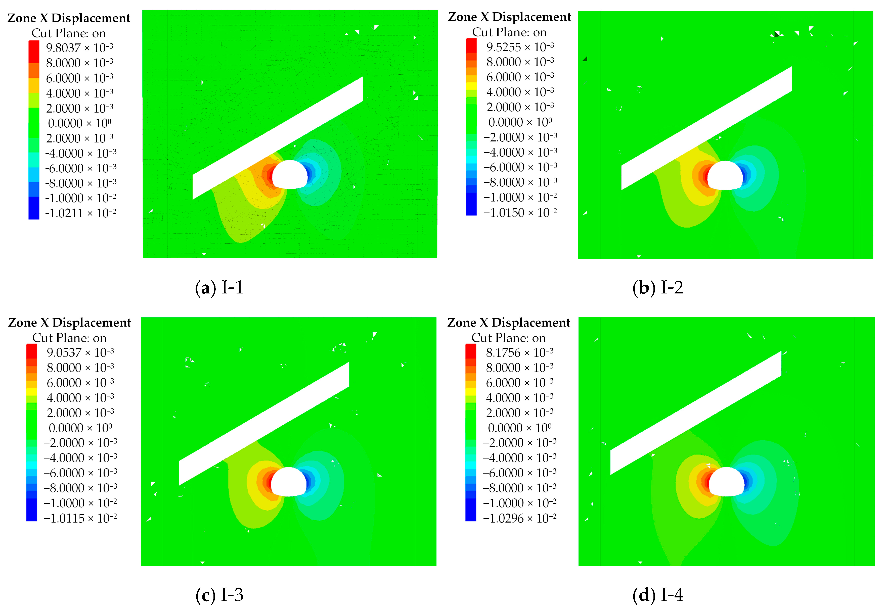
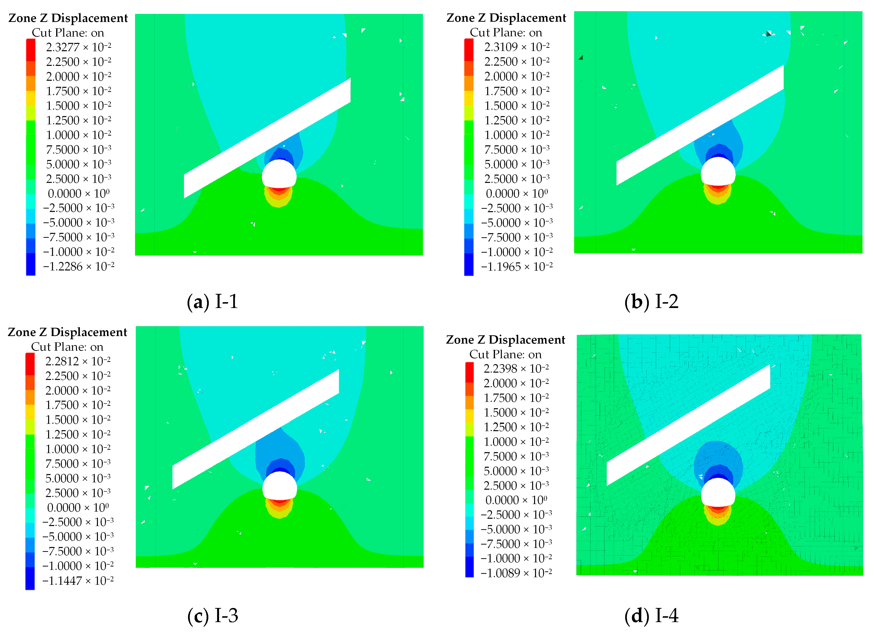
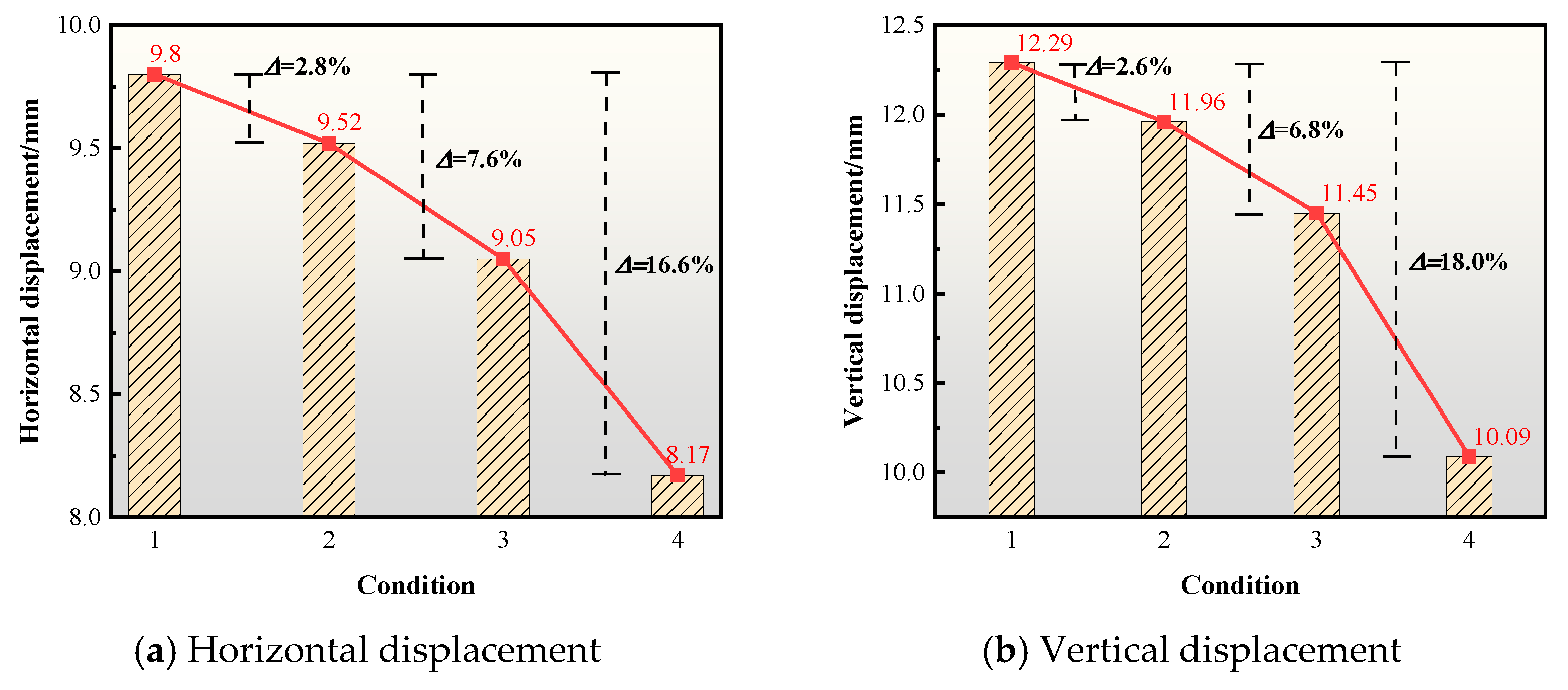
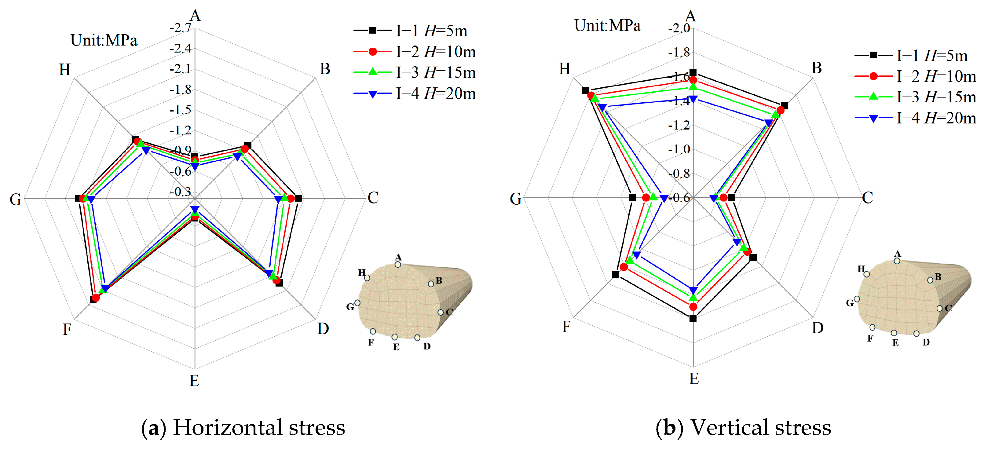
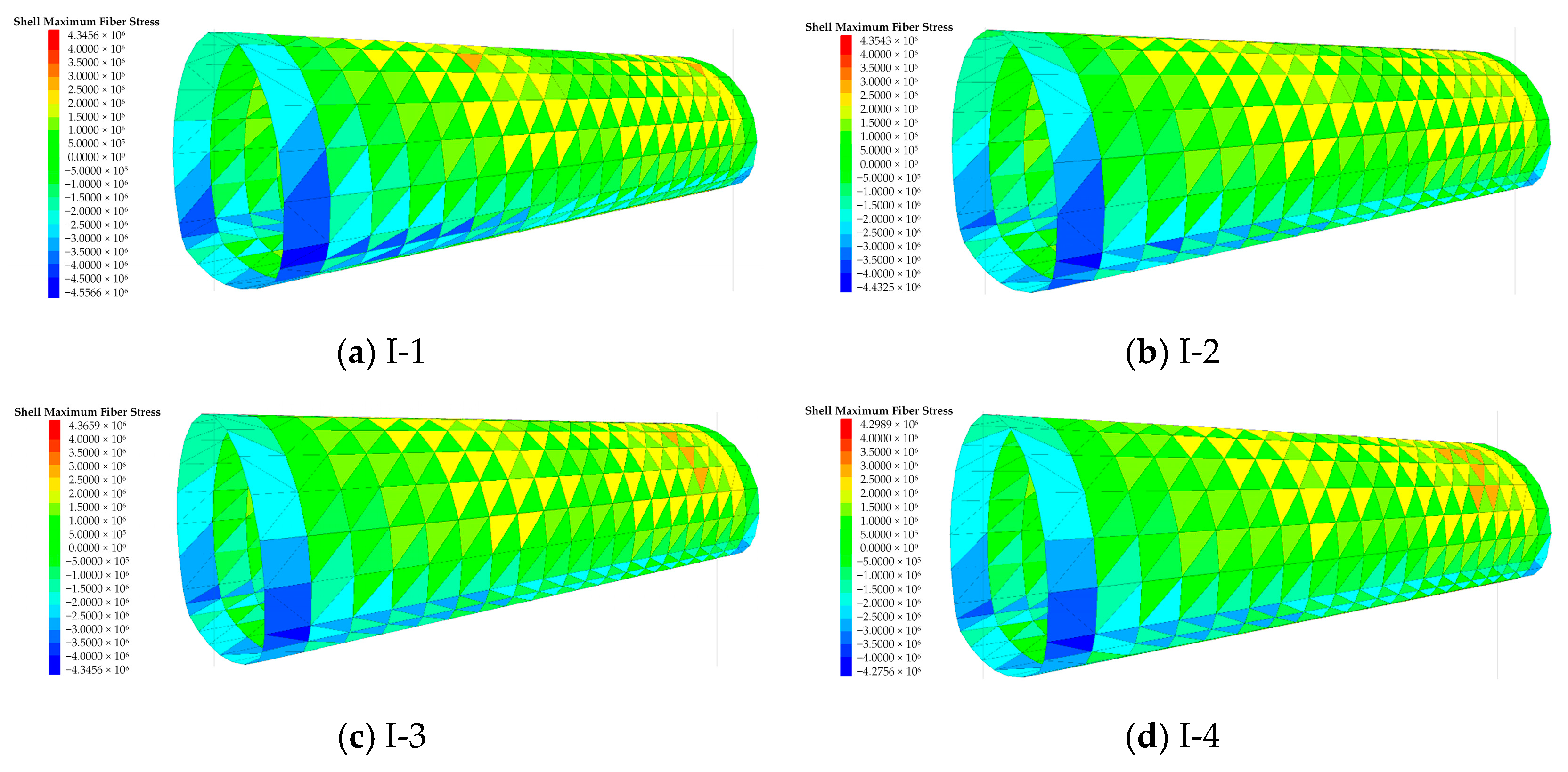
4.1. Influence of Distance

Numerical simulation studies of different distances were conducted, as outlined in Table 2. The horizontal and vertical displacements of the surrounding rock at the 20 m cross-section are depicted in Figure 3, Figure 4 and Figure 5, respectively. These figures show that when the distance is 5 m, 10 m, 15 m, and 20 m, respectively, the horizontal displacements of the left hance of the surrounding rock are 9.80 mm, 9.52 mm, 9.05 mm, and 8.17 mm, while the vertical displacements of the vault are 12.29 mm, 11.96 mm, 11.45 mm, and 10.09 mm. Compared to 5 m, the horizontal displacements of the left hance decreased by 2.8%, 7.6%, and 16.6%, respectively, and the crown displacements decreased by 2.6%, 6.8%, and 18.0%. The above data indicate that as the distance increases, both the horizontal and vertical displacements of the surrounding rock decrease continuously. The deformation of the left hance and the settlement displacement of the crown of the surrounding rock decrease accordingly. At 5 m, the deformation and settlement displacement of the left hance and crown reach their maximum values, indicating the poorest stability of the surrounding rock. From the above-mentioned rock displacement changes, it is evident that the deformation and settlement are most pronounced as the distance increases from 5 m to 10 m. Since this study neglects the impact of loosened rock mass zones, the actual displacements will be slightly larger than those monitored here. However, the overall trend in displacement development will be similar [40].
To study the stress variation characteristics of the surrounding rock around the tunnel, the stress distribution of surrounding rock at various monitoring points under different distances at the 20 m section is shown in Figure 6. In Figure 6, it is evident that due to the goaf cavity being close to the left hance, the left side is more affected by the goaf than the right side. The horizontal stress reaches its maximum value at the arch foot, while the vertical stress peaks at the hance. When the distance is 5 m, 10 m, 15 m, and 20 m, respectively, the horizontal stress at the left arch foot of the surrounding rock is 2.31 MPa, 2.25 MPa, 2.11 MPa, and 2.05 MPa, while the vertical stress at the left hance is 1.85 MPa, 1.79 MPa, 1.75 MPa, and 1.66 MPa. Compared to a distance of 5 m, the horizontal stress at the left arch foot decreased by 2.6%, 8.6%, and 11.3%, respectively, and the vertical stress at the crown decreased by 3.2%, 5.4%, and 10.3%. Therefore, it can be concluded that as the distance increases, both the horizontal and vertical stresses in the tunnel decrease, indicating a lighter collapse degree at the tunnel crown and greater stability of the surrounding rock. In this paper, the displacement and stress changes in the tunnel surrounding rock under the influence of a goaf at different distances are similar to the results of Huang’s physical model verification [40].
Figure 7 shows the maximum axial force of the initial support of the tunnel under different distances of the goaf. The initial support axial force is positive under tension and negative under compression. In Figure 7, it is observed that the initial support axial forces are higher at the tunnel arch than at the arch springing and haunch. Specifically, at the tunnel arch, the maximum initial support axial forces are 4556 kN, 4432 kN, 4345 kN, and 4275 kN, respectively. Thus, it can be concluded that the maximum variation in the initial support axial force occurs when the distance ranges from 5 m to 10 m. Specifically, when the distance is 5 m, the initial support axial force reaches its maximum, indicating greater instability of the support structure.

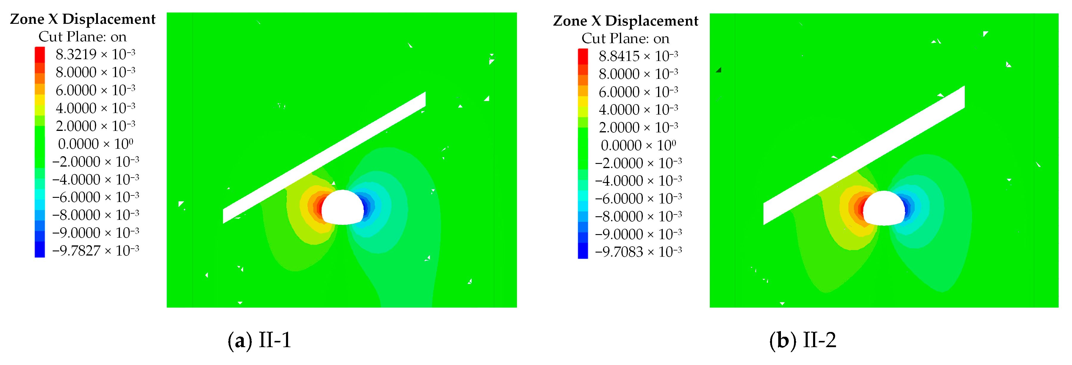
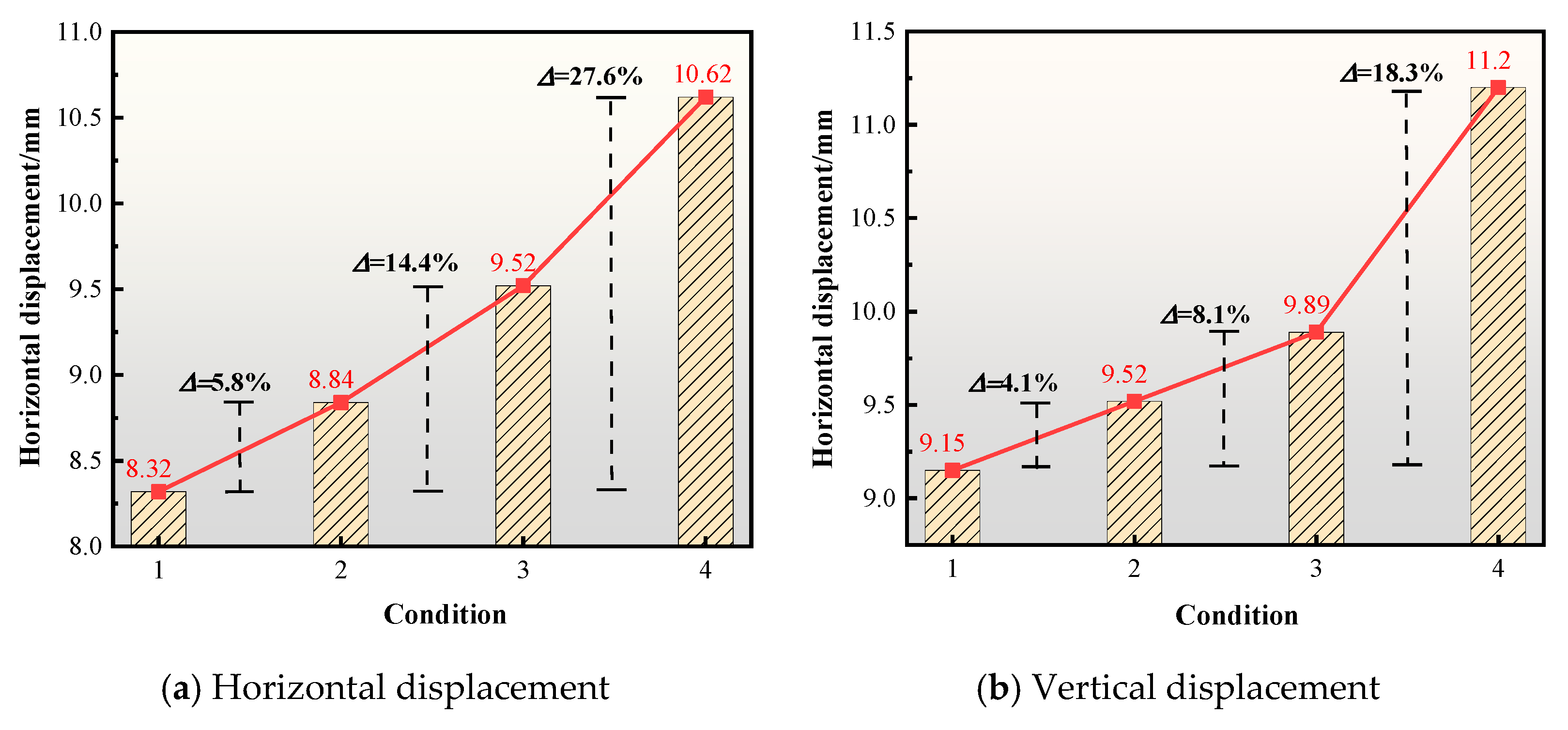
4.2. Influence of Scale

According to the situations shown in Table 2, numerical simulations were conducted to investigate the effects of different scales of goafs. The horizontal and vertical displacements of the surrounding rock at the 20 m section under different scales of goafs are illustrated in Figure 8, Figure 9 and Figure 10, respectively. In Figure 8, Figure 9 and Figure 10, it can be observed that as the scale of the goaf increases, both the horizontal and vertical displacements of the surrounding rock increase. When the diameter is 5 m, 7.5 m, 10 m, and 12.5 m, respectively, the horizontal displacements of the left hance of the surrounding rock are 8.32 mm, 8.84 mm, 9.52 mm, and 10.62 mm, while the vertical displacements of the vault are 10.65 mm, 11.26 mm, 11.97 mm, and 13.37 mm. Compared to a goaf diameter of 5 m, the shoulder displacements increased by 5.8%, 14.4%, and 27.6%, respectively, and the crown displacements increased by 5.7%, 12.4%, and 20.3%. As the scale of the goaf increases, both the horizontal and vertical displacements of the surrounding rock continuously increase, leading to a decrease in the stability of the surrounding rock. When the diameter of the goaf cavity increases from 10 m to 12.5 m, the changes in horizontal displacement at the hance and vertical displacement at the vault of the surrounding rock become most pronounced. Consequently, the collapse deformation of the tunnel vault increases with the increasing scale of the goaf, and larger goaf scales also result in a larger collapse zone.
Figure 11 shows the surrounding rock stress of the tunnel under different scales of goafs. It shows that the horizontal stress in the left abutment of the surrounding rock is 2.01 MPa, 2.13 MPa, 2.25 MPa, and 2.36 MPa, respectively, when the diameter is 5 m, 7.5 m, 10 m, and 12.5 m. The vertical stress at the left abutment of the surrounding rock is 1.59 MPa, 1.65 MPa, 1.79 MPa, and 1.88 MPa, respectively. Compared to a diameter of 5 m, the horizontal stress at the left abutment decreased by 5.9%, 11.9%, and 17.4%, while the vertical stress at the crown decreased by 3.8%, 12.5%, and 18.2%, respectively. As the scale increases, the horizontal stress at the tunnel shoulders increases continuously, with the concentration of vertical stress at the tunnel foot becoming more pronounced. Larger goafs result in more severe settlement of the lower tunnel structure, with settlement increasing uniformly with the scale of the goaf, thereby enlarging the area of settlement under the tunnel.
Figure 12 shows the maximum axial force of the initial support of the tunnel under different scales of goafs. In Figure 12, it is evident that the initial support forces at the crown and foot of the initial support are relatively minor, with some anchor rods even experiencing negative axial forces, indicating compression. However, the initial support axial forces at the crown of the goaf are mostly positive, effectively controlling the convergence of the crown and allowing the support system to perform optimally. With the increase in the goaf scale, the maximum initial support axial force shows an increasing trend. For goaf diameters of 5 m, 7.5 m, 10 m, and 12.5 m, the maximum initial support axial forces are 4123 kN, 4256 kN, 4432 kN, and 4659 kN, respectively. As the goaf scale increases, the initial support axial forces notably increase, leading to a greater degree of depression and collapse range. In particular, the initial support axial force reaches its maximum at the front end of the tunnel, necessitating reinforced support measures to prevent collapse at the tunnel entrance.

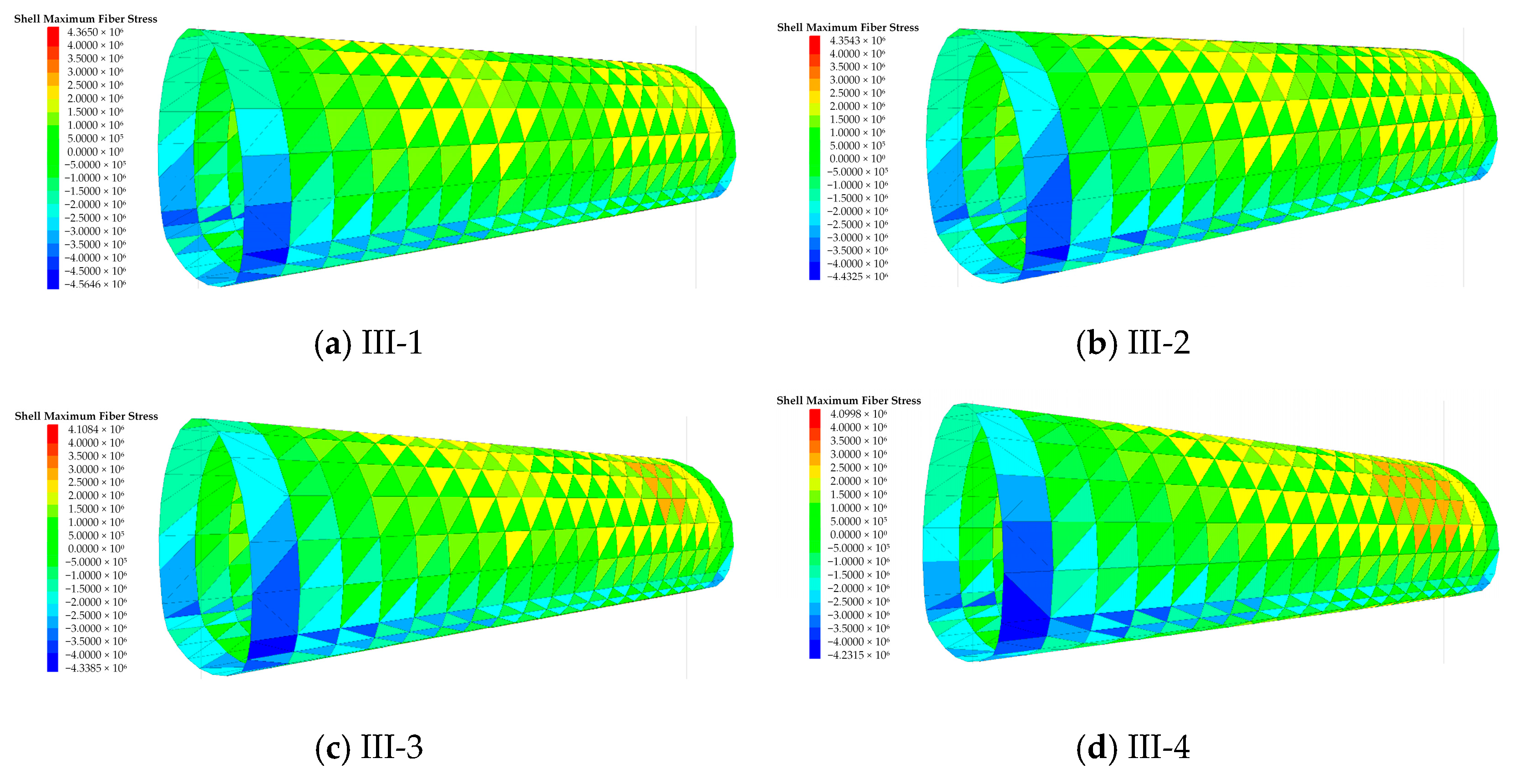
4.3. Influence of Angle

In Figure 13, Figure 14 and Figure 15, it is observed that the horizontal displacement of the surrounding rock decreases while the vertical displacement increases with different angles. When the angles are 15°, 30°, 45°, and 60°, respectively, the horizontal displacements of the left arch foot of the surrounding rock are 9.15 mm, 9.52 mm, 9.89 mm, and 11.2 mm, and the vertical displacements of the vault are 12.62 mm, 11.96 mm, 10.59 mm, and 9.56 mm. Compared to 15°, the horizontal displacements of the left arch foot increased by 4.1%, 8.1%, and 18.3%, respectively, while the displacements of the vault decreased by 5.2%, 16.1%, and 24.2%. As the angle increases, the horizontal displacement of the surrounding rock gradually increases, while the vertical displacement decreases. Due to the tendency of the surrounding rock around the tunnel to displace toward the goaf, the proportion of vertical displacement in the total displacement gradually increases. Consequently, the overall displacement shifts toward being predominantly vertical with the increasing angle of the goaf, resulting in a gradual reduction in vertical displacement. This phenomenon is similar to the research results of Liu [41]. The smaller the dip angle, the greater the vault settlement. The larger the dip angle, the greater the horizontal convergence of the two sides of the tunnel.
Figure 16 shows the surrounding rock stress of the tunnel under different angles of goafs. In Figure 16, it is evident that the horizontal stresses at the foot and crown of the tunnel arch are significantly influenced by the angle of the goaf. As the angle increases, the horizontal stress at the foot increases continuously, while the vertical stress decreases. When the angle is 60°, the horizontal stress at the right foot is 2.43 MPa. Compared to the angle of 15°, the horizontal displacement at the right crown increases by 13.9%. At the angle of 60°, the vertical stress at the shoulder is 1.97 MPa. Compared to the angle of 15°, the vertical displacement at the crown decreases by 10.7%. Therefore, with the increasing angle, the stress concentration at the right crown becomes more pronounced, leading to increased depression, while the collapse deformation at the crown diminishes continuously.
Figure 17 shows the maximum axial force of the initial support of the tunnel under different angles of goafs. In Figure 17, it can be observed that the magnitude of the initial support axial forces increases as the tunnel advances continuously toward the adjacent goaf. At the arch section of the tunnel near the goaf, the initial support bears significantly higher positive axial forces compared to locations further from the goaf. This indicates that the initial support of the surrounding tunnel rock near the goaf effectively provides excellent support, thereby controlling rock deformation and improving the stress conditions of the tunnel support structure. With the increasing angle, the maximum axial force of the initial support shows an increasing trend. For angles of 15°, 30°, 45°, and 60°, respectively, the maximum initial support axial forces are 4564 kN, 4432 kN, 4338 kN, and 4231 kN. As the angle increases, the structural bearing capacity of the initial support becomes stronger.

5. Guiding Significance for Engineering

Through the above analysis, the deformation characteristics of the surrounding rock of the tunnel undercrossing multi-situational goafs were obtained. The maximum values of horizontal convergence at the arch waist, numerical settlement at the vault, and axial force of the initial support under various goaf situations are shown in Figure 18c–e. Situations 1–4 correspond to I-1–I-4; situations 5–8 correspond to II-1–II-4; and situations 9–12 correspond to III-1–III-4, respectively. Figure 18c shows that after increasing the distance between goaf situations I-1–I-3 by 10 m, the vertical displacement difference is 0.84 mm, and after further increasing the distance by 5 m from I-3 to I-4, the vertical displacement difference is 1.36 mm. The vertical displacements for the four situations decrease by 2.6%, 6.8%, and 18.0%, respectively, indicating that as the distance increases, the impact of the goaf area on vertical displacement gradually diminishes. Figure 18d,e show that the trends of horizontal convergence and maximum axial force of the initial support are similar to the vertical displacement deformation trend. The distance in the range of 5–15 m has the greatest impact on tunnel stability. When the distance exceeds 15 m, the impact gradually decreases. Therefore, it can be inferred that in this case, the goaf area affects the deformation of the surrounding rock up to a distance of about 15 m, which is approximately 1.13 times the tunnel span. Figure 18c–e show that the impact of different diameters on the stability of the surrounding rock follows a similar increasing trend; the larger the goaf scale, the greater the impact on the stability of the surrounding rock. As shown in Figure 18c, an increase in the angle of the goaf area results in a decreasing impact on the vertical displacement of the surrounding rock, whereas the impact on the horizontal displacement and the maximum axial force of the initial support is the opposite. That is, the greater the angle, the larger the horizontal displacement and maximum axial force of the initial support, with the horizontal displacement trend increasing first and then decreasing. In this case, when the angle is less than 45°, as shown in Figure 18c, the settlement at the tunnel crown is larger; when the angle is greater than 45°, as shown in Figure 18d,e, the impact of the goaf area on the horizontal convergence of the surrounding rock is significantly reduced.
In the tunnel line selection, the tunnel should be kept as far away from the goaf area as possible. However, if it is unavoidable for the tunnel to cross the goaf area in practical engineering, the distance should be maintained at more than 1.13 times the tunnel span, or auxiliary measures such as reinforcement should be adopted to ensure the safety and smooth progress of the project. In the design of the tunnel support scheme, different support schemes should be designed according to the location and direction of different goafs to ensure the stability of tunnel construction and operation, which means that excavation support needs to be more flexible to adapt to different conditions of the goaf tunnel surrounding rock. The above-mentioned deformation characteristics of the surrounding rock can effectively guide the safe construction of tunnels undercrossing goaf areas, as illustrated in Figure 18. Firstly, the location of the goaf area at the tunnel construction site is determined based on physical detection and drilling results, as shown in Figure 18a,b. Figure 18a presents the resistivity profile image of the Huaying Mountain High-Speed Railway Tunnel site, where the cavity shown is part of a goaf within the mountain. Figure 18b shows the drilling process of the CASAGRADNE-C6xp-2 multi-functional drilling rig at the Huaying Mountain High-Speed Railway Tunnel site. After combining physical detection and drilling to determine the location of the goaf area, the corresponding reinforcement measures can be designed. However, due to the complex conditions of the goaf areas on site, including many goaf areas left by private coal mining activities from the last century, flexible reinforcement schemes need to be designed according to different situations. The deformation characteristics of the surrounding rock and the force laws of the initial support derived in this paper (as shown in Figure 18c–e) can solve this problem. By assessing the force conditions of the surrounding rock and the initial support of the tunnels in different goafs, effective treatment plans can be provided. This outcome can save construction costs, control construction periods, and effectively guide the on-site construction of the Huaying Mountain High-Speed Railway Tunnel undercrossing goafs. Based on the different distances presented in this paper, as shown in Figure 18f, the most cost-effective and time-efficient reinforcement schemes can be designed. Similarly, reinforcement schemes corresponding to different angles and goaf area scales can be designed (not shown in Figure 18 due to space constraints). Therefore, based on the multi-situational goafs detected in subsequent site surveys and combining the deformation characteristics of the surrounding rock and the force laws of the initial support under the 12 goaf area situations studied in this paper, the optimal reinforcement schemes suitable for the construction site conditions can be designed, as shown in Figure 18g. The results of this study provide the scientific basis and technical support for similar tunnel engineering projects, help improve engineering quality, ensure construction safety, control engineering costs, and have significant guiding significance for on-site construction.

6. Conclusions

The simulation in this study was conducted using MIDAS to model the tunnel dimensions based on the construction site. The model was then imported into FLAC software to simulate the stability of the tunnel surrounding rock and the initial support when crossing different goaf conditions. Based on the simulation results, the deformation patterns and stress conditions of the surrounding rock and the initial support under various goaf scenarios were analyzed. The results are as follows:
(1)
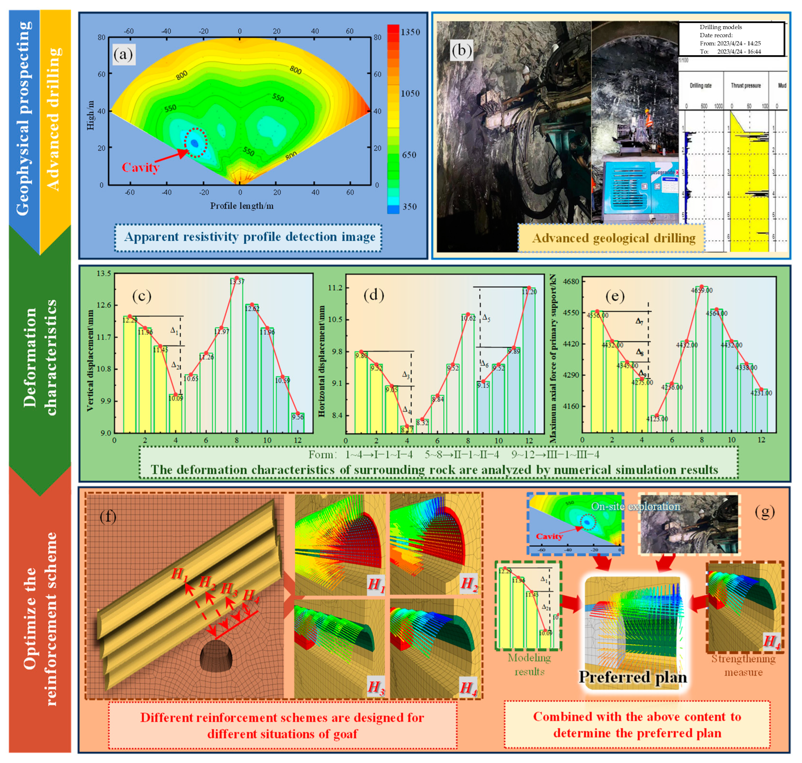
Since the goaf cavity is close to the left hance of the tunnel, the left arch waist of the tunnel is significantly affected by the goaf. As the distance increases, the horizontal displacement of the left arch waist continuously decreases. When the distance reaches 20 m, the horizontal displacement of the left arch waist decreases by 16% compared to when the distance is 5 m, and the vertical displacement of the vault decreases by 18%. As the distance continues to increase, both the horizontal and vertical displacements of the tunnel show a decreasing trend. The degree of collapse and subsidence of the surrounding rock at the tunnel vault becomes less severe, and the maximum axial force of the initial support shows a significant change when the distance to the goaf increases from 5 m to 10 m, decreasing by 124 KN. However, when the distance to the goaf increases from 15 m to 20 m, the change is relatively minor, with a reduction of only 70 KN. Compared to the change between 5 m and 10 m, this variation is only 56%. This indicates that once the distance increases beyond a certain point, the maximum axial force in the initial support will no longer experience significant changes.
(2)
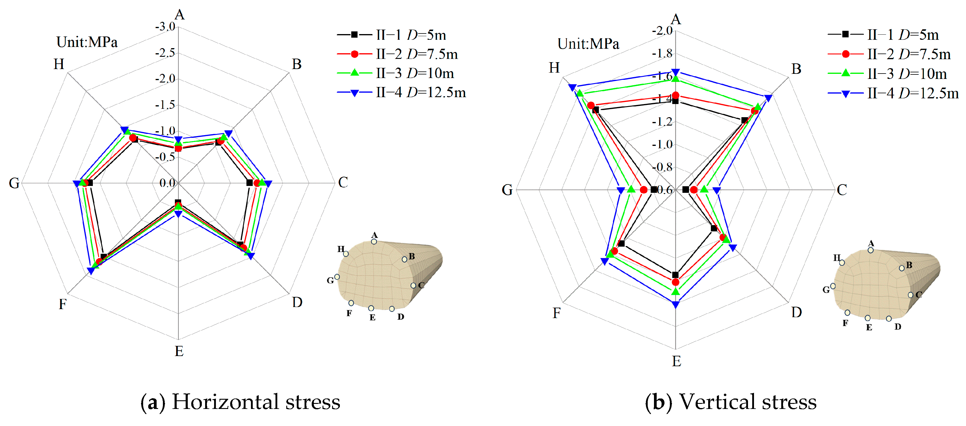
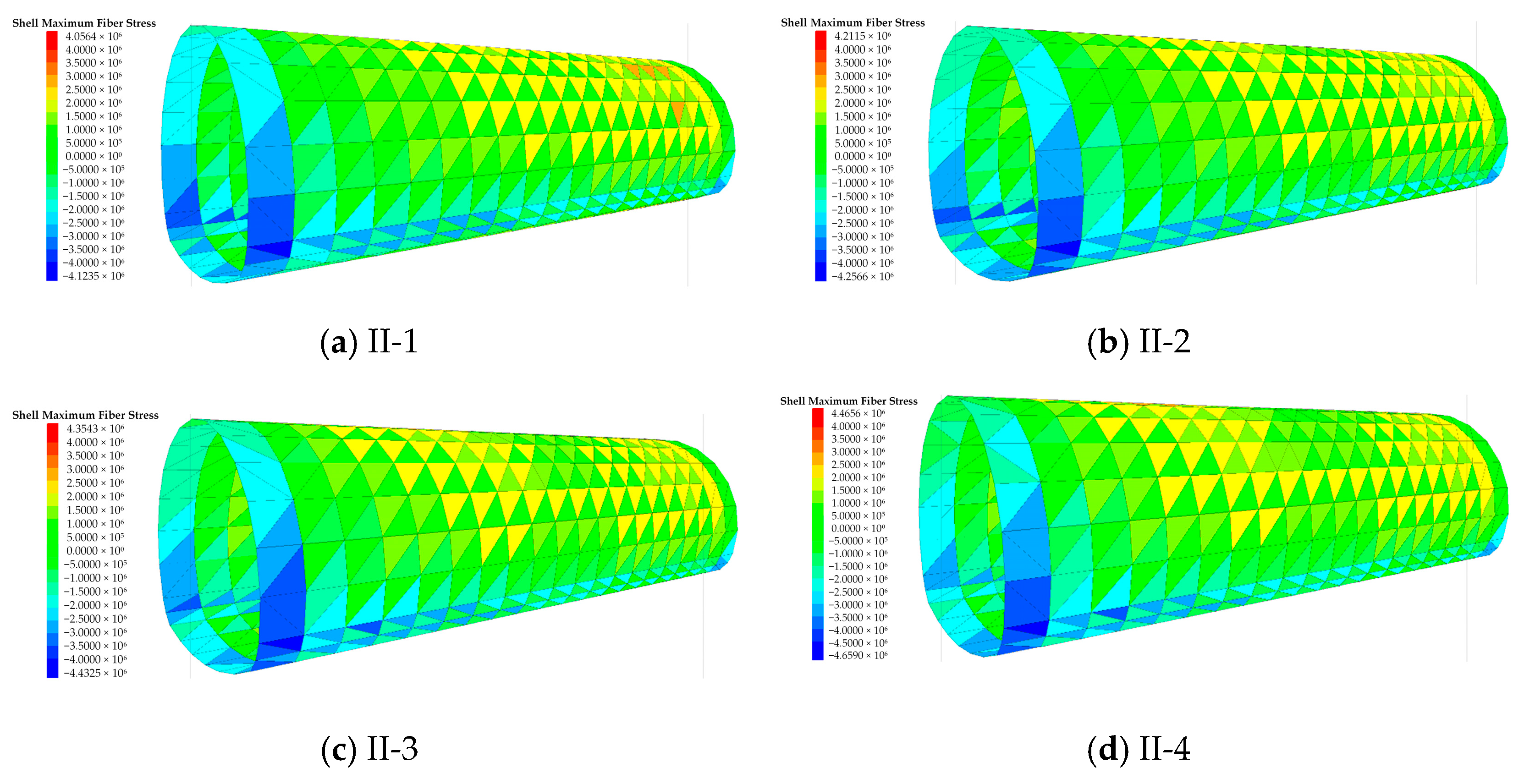
As the scale of the goaf gradually increases, the deformation values at key positions of the surrounding rock continuously rise. When the diameter reaches 12.5 m, the horizontal displacement of the arch waist increases by 27.6% compared to the 5 m case, and the vertical displacement of the vault increases by 20.3%. As the scale of the goaf increases, the degree of local subsidence at the tunnel vault becomes more pronounced; the phenomenon of longitudinal arch bottom uplift becomes more evident; and the range of subsidence along the longitudinal direction is significantly enlarged. As the goaf cavity diameter changes from 5 m to 20 m, the variation in the maximum axial force of the initial support is relatively uniform and gradual, differing from the impact caused by distance.
(3)
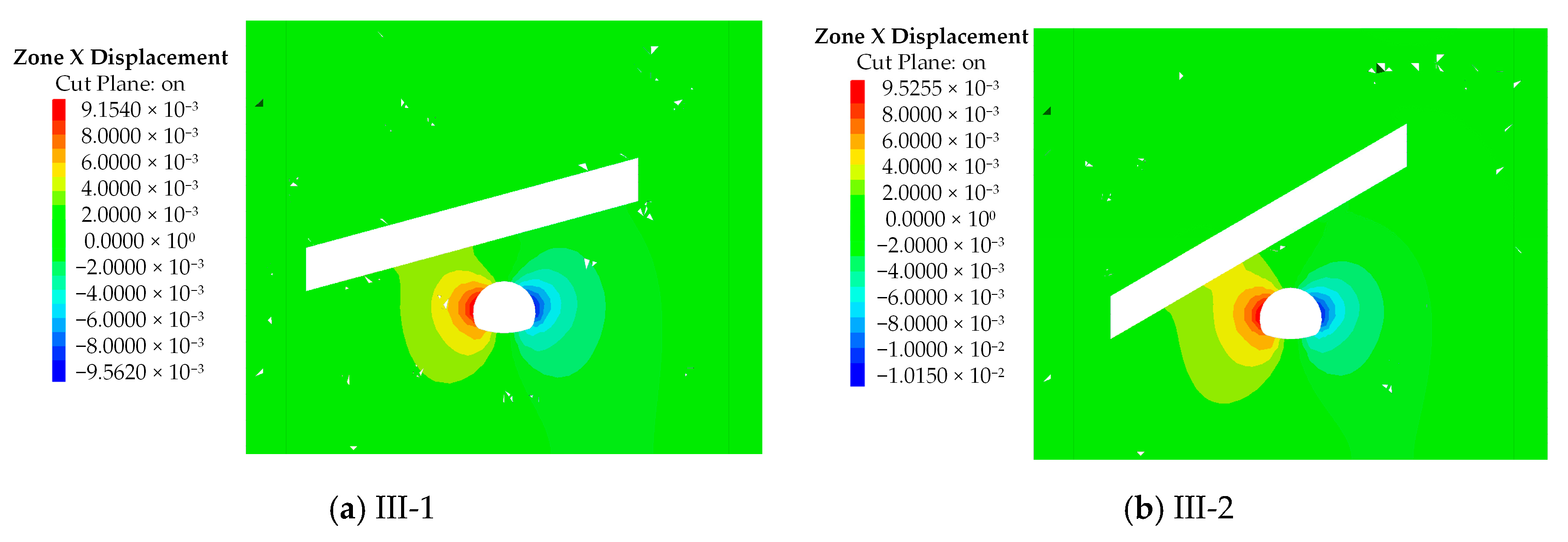
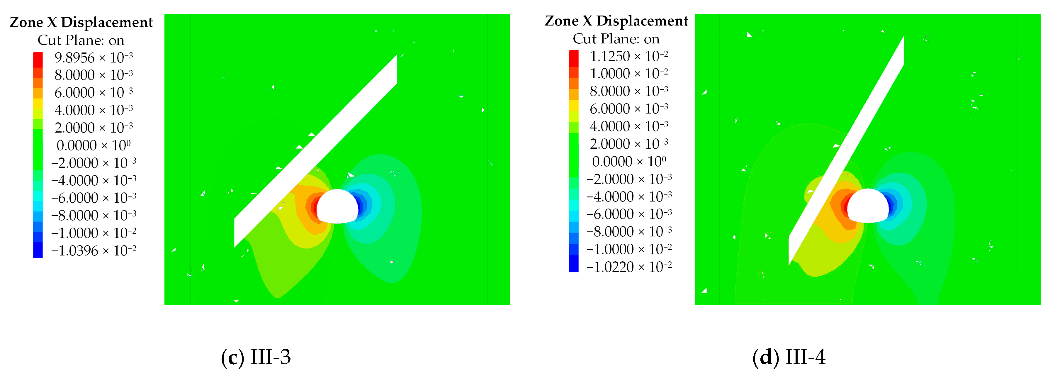
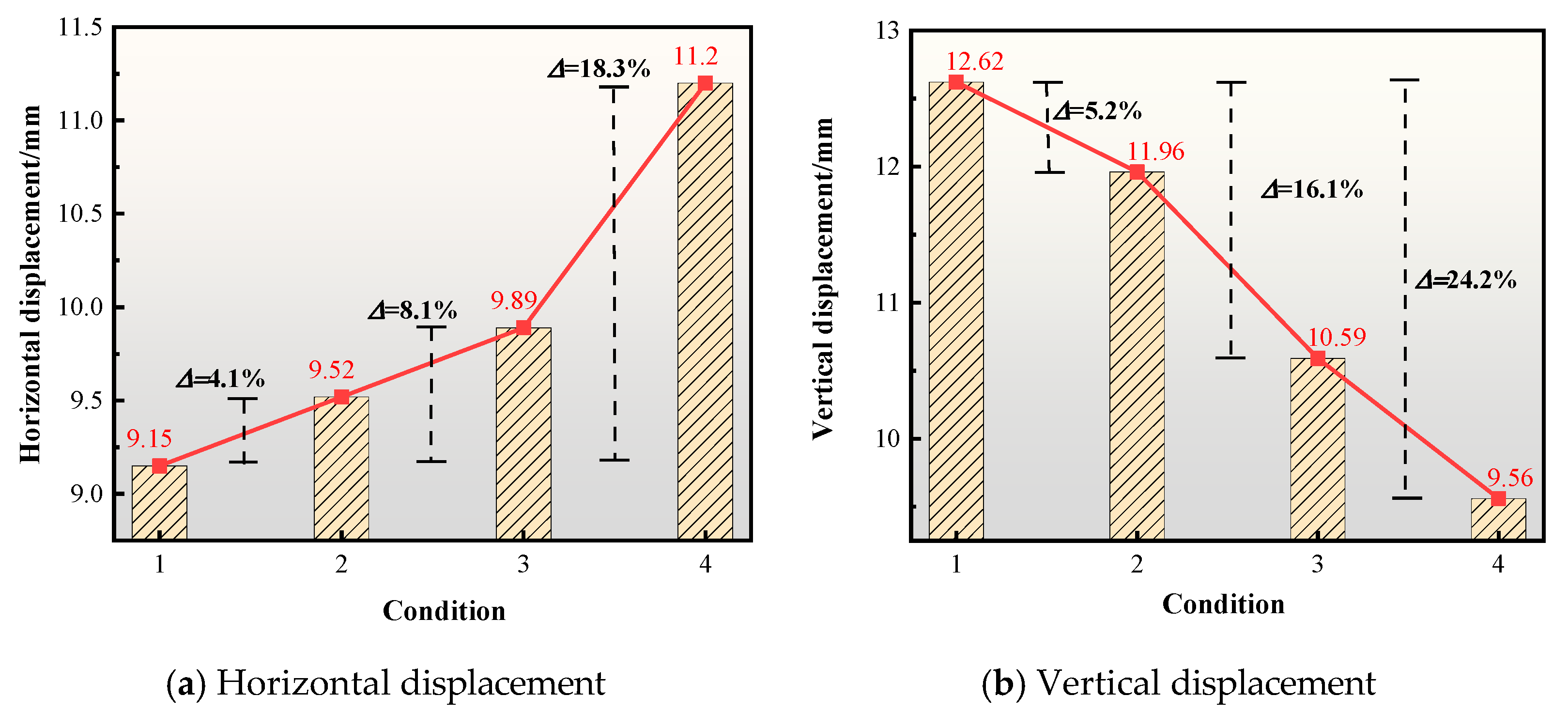
As the angle gradually increases, the horizontal displacement distribution of the walls on both sides of the tunnel ceases to be symmetrical. When the angle reaches 60°, the horizontal displacement of the right arch waist increases by 18.3% compared to when the angle is 15°, while the vertical displacement decreases by 24.2%. It can be observed that with the increasing angle, the degree and extent of subsidence of the right arch waist continually increase, while the collapse degree and range of the vault decrease. As the goaf angle varies from 15° to 60°, the change in the maximum axial force of the initial support is relatively uniform. This phenomenon is similar to the effect of different goaf diameters and differs from the impact caused by distance.
(4)
Based on the analysis of the deformation characteristics of the surrounding rock and the stress on the initial support, to minimize the adverse effects of overlying goaf areas on the stability of the surrounding rock during tunnel construction, it is recommended in actual alignment selection that the tunnel should be positioned as far away from goaf areas as possible. If crossing a goaf area is unavoidable, the tunnel should maintain a distance from the goaf area greater than 1.13 times the tunnel span. It is also advisable to avoid crossing larger scale goaf areas and minimize the angle. During the construction process, supplementary measures such as grouting reinforcement should be considered based on the deformation characteristics of the surrounding rock and the stress behavior of the initial support under different goaf situations, as discussed in this paper. This will help reduce the possibility of significant deformation or collapse of the surrounding rock.

Author Contributions

Conceptualization, M.Z. and J.G.; methodology, J.G.; software, S.L. (Shifan Liang); investigation, S.L. (Shaohua Li) and F.S.; resources, J.G.; data curation, M.Z. and S.L. (Shifan Liang); writing—original draft preparation, M.Z.; writing—review and editing, M.Z.; visualization, S.L. (Shaohua Li); supervision, F.S.; project administration, S.L. (Shaohua Li); funding acquisition, J.G. All authors have read and agreed to the published version of the manuscript.

Funding

This study was funded by the China Railway 15th Bureau Group Co., Ltd. (Grant No. 2023B7), China Railway 15th Bureau Group Third Engineering Co., Ltd. (Grant No. H23-703), and China State Construction Railway Investment Engineering Group Co., Ltd. (Grant No. H20-411).

Institutional Review Board Statement

Not applicable.

Informed Consent Statement

Not applicable.

Data Availability Statement

The original contributions presented in the study are included in the article, further inquiries can be directed to the corresponding author.

Acknowledgments

The authors greatly appreciate the financial support received from the funding bodies and are grateful to the reviewers for their valuable comments and suggestions to improve the quality of the paper.

Conflicts of Interest

Authors Shaohua Li and Fengwei Sun were employed by the company China Railway 15th Bureau Group Co., Ltd. The authors declare that this study received funding from China Railway 15th Bureau Group Co., Ltd., China Railway 15th Bureau Group Third Engineering Co., Ltd. and China State Construction Railway Investment Engineering Group Co., Ltd. The funder was not involved in the study design, collection, analysis, interpretation of data, the writing of this article or the decision to submit it for publication.

References

  1. Mabe Fogang, P.; Liu, Y.; Zhao, J.-L.; Ka, T.A.; Xu, S. Analytical Prediction of Tunnel Deformation Beneath an Inclined Plane: Complex Potential Analysis. Appl. Sci. 2023, 13, 3252. [Google Scholar] [CrossRef]
  2. Jia, J.X. Application of PS-INSAR Technique on Health Diagnosis of the Deformable Body on Front Slope beside Mountain Tunnel Portal. Math. Probl. Eng. 2020, 2020, 823382. [Google Scholar] [CrossRef]
  3. Celada, B.; Bieniawski, Z. Ground Characterization and Structural Analyses for Tunnel Design; CRC: Boca Raton, FL, USA, 22 July 2019. [Google Scholar]
  4. Sousa, L. Learning with Accidents and Damage Associated. In Geotechnical Risk in Rock Tunnels (7–39); Taylor & Francis: Abingdon, UK, 2006. [Google Scholar]
  5. Sousa, L.; Einstein, H. Lessons from Accidents During Tunnel Construction. Tunn. Undergr. Space Technol. 2021, 113, 103916. [Google Scholar] [CrossRef]
  6. Karakus, M.; Fowell, R. An Insight into The New Austrian Tunnelling Method (NATM). In Proceedings of the 7th Regional Rock Mechanics Symposium, Sivas, Turley, 21–22 October 2004; Available online: https://hdl.handle.net/2440/57176 (accessed on 10 August 2024).
  7. Shang, Y.D.; Guo, Y.P.; Zhang, W.Q. Numerical simulation on the deformation and failure of the goaf surrounding rock in Heiwang mine. IOP Conf. Ser. Earth Environ. Sci. 2018, 121, 052034. [Google Scholar] [CrossRef]
  8. Wang, L.H. Study on Safety and Stability Evaluation and Treatment Measures of Highway Tunnel Structure in Underlying Goaf. Highway 2020, 65, 308–315. [Google Scholar]
  9. Wang, Q.; He, M.C.; Yang, J.; Gao, H.K.; Jiang, B.; Yu, H.C. Study of a no-pillar mining technique with automatically formed gob-side entry retaining for longwall mining in coal mines. Int. J. Rock Mech. Min. 2018, 110, 1–8. [Google Scholar] [CrossRef]
  10. Wang, Q.; Gao, H.K.; Jiang, B.; Li, S.C.; He, M.C.; Qin, Q. In-situ test and bolt-grouting design evaluation method of underground engineering based on digital drilling. Int. J. Rock Mech. Min. 2021, 138, 104575. [Google Scholar] [CrossRef]
  11. Wang, S.R.; Zhang, H.Q.; Shen, N.Q.; Cao, H.Y. Analysis of deformation and stress characteristics of highway tunnels above mined-out regions. Chin. J. Rock Mech. Eng. 2009, 28, 1144–1151. [Google Scholar] [CrossRef]
  12. Li, J.W. Research on the Catastrophic Evolution Mechanism and Safety Control Key Technology of Highway Tunnel Excavation with Upper Goaf. Ph.D. Thesis, University of Science and Technology Beijing, Beijing, China, 2021. [Google Scholar] [CrossRef]
  13. Yu, H.P.; He, Y.L.; Zhang, G.Z.; Cai, J.P. Analysis of Settlement in Coal Mine Goaf for the Exit Section of Hejiadi Tunnel of Shanghai-Kunming High speed Railway. J. Railw. Eng. Soc. 2020, 37, 32–37+97. [Google Scholar]
  14. Hu, Y.Z. Analysis and Study of the Railway Tunnel Diseases in Goaf by InSAR Technology. J. Railw. Eng. Soc. 2020, 37, 59–62+85. [Google Scholar]
  15. Cai, W.Y.; Chang, Z.C.; Zhang, D.S.; Wang, X.F.; Cao, W.H.; Zhou, Y.Z. Roof filling control technology and application to mine roadway damage in small pit goaf. Int. J. Min. Sci. Technol. 2019, 29, 477–482. [Google Scholar] [CrossRef]
  16. Krzysztof, S. Comparative Analysis of the Mining Cribs Models Filled with Gangue. Energies 2020, 13, 5290. [Google Scholar] [CrossRef]
  17. Ma, W.Q.; Wang, T.X.; Zhang, H. Regenerated roof structure and grouting-bolt support of roadway. J. Min. Saf. Eng. 2018, 35, 693–700. [Google Scholar] [CrossRef]
  18. Jiang, P.F.; Xiao, P.; Meng, F.B.; Jing, S.L.; Zhang, J.K.; Wang, G.; Zhao, P. Application Study on Active Advanced Support Technology in Deep Roadway under Mine Goaf. Geofluids 2020, 13, 865238. [Google Scholar] [CrossRef]
  19. Xie, C.Y.; Jia, N.; He, L.W. Study on the Instability Mechanism and Grouting Reinforcement Repair of Large-Scale Underground Stopes. Adv. Civ. Eng. 2020, 10, 832012. [Google Scholar] [CrossRef]
  20. Bernaud, D.; Buhan, P.D.; Maghous, S. Numerical simulation of the convergence of a bolt-supported tunnel through a homogenization method. Int. J. Numer. Anal. Meth. Geomech. 1995, 19, 267–288. [Google Scholar] [CrossRef]
  21. Bernaud, D.; Maghous, S.; Buhan, P.D.; Couto, E. A numerical approach for design of bolt-supported tunnels regarded as homogenized structures. Tunn. Undergr. Space Technol. Inc. Trenchless Technol. Res. 2009, 24, 533–546. [Google Scholar] [CrossRef]
  22. Cai, Y.; Esaki, T.; Jiang, Y.J. An analytical model to predict axial load in grouted rock bolt for soft rock tunnelling. Tunnell. Undergr. Space Technol. 2010, 26, 100–123. [Google Scholar] [CrossRef]
  23. Starfield, A.M.; Cundall, P.A. Towards a methodology for rock mechanics modelling. Int. J. Rock Mech. Min. Sci. Geomech. Abstr. 1988, 25, 99–106. [Google Scholar] [CrossRef]
  24. Grenon, M.; Hadjigeorgiou, J. Open Stope Stability Using 3D Joint Networks. Rock Mech. Rock Eng. 2003, 36, 183–208. [Google Scholar] [CrossRef]
  25. Karim, R.; Simangunsong, M.G.; Sulistianto, B.; Lopulalan, A. Stability Analysis of Paste Fill as Stope Wall using Analytical Method and Numerical Modeling in TheKencana Underground Gold Mining with Long Hole Stope Method. Procedia Earth Planet. Sci. 2013, 6, 474–484. [Google Scholar] [CrossRef]
  26. Choi, J.; Kim, K.; Song, S.; Jo, M. A Study on the Correlation between Coal Mining Subsidence and Underground Goaf. Econ. Environ. Geol. 2008, 41, 453–464. [Google Scholar]
  27. Samir, M.; Denise, B.; Eduardo, C. Three-dimensional numerical simulation of rock deformation in bolt-supported tunnels: A homogenization approach. Tunn. Undergr. Space Technol. Inc. Trenchless Technol. Res. 2012, 31, 68–79. [Google Scholar] [CrossRef]
  28. Sun, F.Y.; Liu, X.L.; Guo, J.Q.; Shi, X.Y.; Wu, W.L.; Zhu, B.Z. Safety distance and energy evolution mechanism of deep tunnel construction when side-crossing a goaf. J. Water Resour. Water Eng. 2021, 32, 193–202. [Google Scholar]
  29. Chen, Y. Study on Stability of Surrounding Rock of Highway Tunnel Passing Through Goaf of Coal Mine. Coal Technol. 2018, 37, 28–30. [Google Scholar] [CrossRef]
  30. Li, J.W.; Feng, S.W.; Zhou, Y. Mechanical mechanism of surrounding rock catastrophe evolution during construction of tunnel under goaf. J. Cent. South Univ. (Sci. Technol.) 2021, 52, 543–554. [Google Scholar]
  31. Huang, H.T.; Cheng, H.; Zhao, H.F.; Cao, G.Y.; Liu, J.W.; Zhai, C.J. Analysis of Surrounding Rock Deformation Law of High-speed Railway Tunnel Passing Through Mined-out Section. Sci. Technol. Eng. 2020, 20, 10900–10906. [Google Scholar]
  32. Li, W.L.; Tu, S.H.; Tu, H.S.; Li, Y.; Liu, X.; Miao, K.J. Failure characteristics and control techniques for mining roadway affected by stress accumulation of residual pillars in contiguous coal seams. Eng. Fail. Anal. 2022, 141, 106646. [Google Scholar] [CrossRef]
  33. Sikora, P.; Wesołowski, M. Numerical assessment of the influence of former mining activities and plasticity of rock mass on deformations of terrain surface. Int. J. Min. Sci. Technol. 2021, 31, 209–214. [Google Scholar] [CrossRef]
  34. Jiang, Z.H. Numerical analysis of the destruction of water-resisting strata in a coal seam floor in mining above aquifers. Min. Sci. Technol. 2011, 21, 537–541. [Google Scholar] [CrossRef]
  35. He, L.; Wu, D.; Ma, L.F. Numerical simulation and verification of goaf morphology evolution and surface subsidence in a mine. Eng. Fail. Anal. 2023, 144, 106918. [Google Scholar] [CrossRef]
  36. Lu, W.; Guo, Z.; Hu, H.; Zhou, Y.Q.; Wang, C.X.; Zhang, B.L. Stability evaluation of mined-out area and Borehole Grouting Treatment-a case study in China. Case Stud. Constr. Mater. 2023, 19, e02596. [Google Scholar] [CrossRef]
  37. Zhang, Q.L.; Wang, C.H.; Han, L.; Hao, J.W.; Qiao, L.; Chen, S.F. Study on Stability Analysis and Treatment of Underground Goaf in Metal Mine. Min. Metall. Explor. 2023, 40, 1973–1985. [Google Scholar] [CrossRef]
  38. He, F.L.; Liu, B.Q.; Wang, D.Q.; Chen, D.D.; Wu, Y.H.; Song, L.M.; Ma, X.; Ye, Q.C.; Jiang, Z.S.; Guo, F.F.; et al. Study on Stability and Control of Surrounding Rock in the Stopping Space with Fully Mechanized Top Coal Caving under Goaf. Energies 2022, 15, 8498. [Google Scholar] [CrossRef]
  39. Cai, G.T.; Sui, W.H.; Wu, S.L.; Wang, J.L.; Chen, J.X. On-Site Monitoring for the Stability Evaluation of a Highway Tunnel above Goaves of Multi-Layer Coal Seams. Appl. Sci. 2021, 11, 7383. [Google Scholar] [CrossRef]
  40. Huang, F.; Shi, X.X.; Wu, C.Z.; Dong, G.F.; Liu, X.C.; Zheng, A.C. Stability analysis of tunnel under coal seam goaf: Numerical and physical modeling. Undergr. Space 2023, 11, 246–261. [Google Scholar] [CrossRef]
  41. Liu, S.B.; Zhou, C.Y.; Fang, Y. Analysis of Excavation Stability of Twin Tunnels Under-crossing Thin Mined-out Coal Area. Railw. Stand. Des. 2015, 10, 128–133. [Google Scholar]
Figure 1. Overview of tunnel and goaf.
Applsci 14 07412 g001
Figure 2. Position relationship between tunnel and goaf.
Applsci 14 07412 g002
Figure 3. Horizontal displacement of surrounding rock of tunnel under different distances of goafs (Units: m).
Applsci 14 07412 g003
Figure 4. Vertical displacement of surrounding rock of tunnel under different distances of goafs (Units: m).
Applsci 14 07412 g004
Figure 5. Displacement of tunnel hance and vault under different distances of goafs.
Applsci 14 07412 g005
Figure 6. Surrounding rock stress of tunnel under different distances of goafs.
Applsci 14 07412 g006
Figure 7. The maximum axial force of initial support of tunnel under different distances of goafs (Units: m).
Applsci 14 07412 g007
Figure 8. Horizontal displacement of surrounding rock of tunnel under different scales of goafs (Units: m).
Applsci 14 07412 g008aApplsci 14 07412 g008b
Figure 9. Vertical displacement of surrounding rock of tunnel under different scales of goafs (Units: m).
Applsci 14 07412 g009
Figure 10. Displacement of tunnel hance and vault under different scales of goafs.
Applsci 14 07412 g010
Figure 11. Surrounding rock stress of tunnel under different scales of goafs.
Applsci 14 07412 g011
Figure 12. The maximum axial force of initial support of tunnel under different scales of goafs (Units: m).
Applsci 14 07412 g012
Figure 13. Horizontal displacement of surrounding rock of tunnel under different angles of goafs (Units: m).
Applsci 14 07412 g013aApplsci 14 07412 g013b
Figure 14. Vertical displacement of tunnel surrounding rock under different angles of go afs (Units: m).
Applsci 14 07412 g014
Figure 15. Displacement of tunnel hance and vault under different angles of goafs.
Applsci 14 07412 g015
Figure 16. Surrounding rock stress of tunnel under different angles of goafs.
Applsci 14 07412 g016
Figure 17. The maximum axial force of initial support of tunnel under different angles of goafs (Units: m).
Applsci 14 07412 g017
Figure 18. Guidance for engineering: (a) The resistivity profile image of the Huaying Mountain High-Speed Railway Tunnel site; (b) The drilling process of the CASAGRADNE-C6xp-2; (c) Changes in vertical displacement; (d) Changes in horizontal displacement; (e) Changes in maximum axial force of initial support; (f) Design of corresponding support schemes for different working conditions; (g) Design the best solution based on the above content.
Applsci 14 07412 g018
Table 1. Mechanical parameters of surrounding rock and initial support.
Nameρ/(kg·m−3)E/GPaμc/MPaφ/(°)K
IV Surrounding Rock225020.30.2300.5
Initial Support2500250.22--
Table 2. Simulation program.
Goaf SituationH/mD/mθ
I: Different distanceI-151030
I-2101030
I-3151030
I-4201030
II: Different scaleII-110530
II-2107.530
II-3101030
II-41012.530
III: Different angleIII-1101015
III-2101030
III-3101045
III-4101060
Disclaimer/Publisher’s Note: The statements, opinions and data contained in all publications are solely those of the individual author(s) and contributor(s) and not of MDPI and/or the editor(s). MDPI and/or the editor(s) disclaim responsibility for any injury to people or property resulting from any ideas, methods, instructions or products referred to in the content.

