Article

Simulation Analysis and Experiment of Piezoelectric Pump with Tapered Cross-Section Vibrator

1
College of Mechanical and Electrical Engineering, Qingdao Agricultural University, Qingdao 266109, China
2
College of Mechanical and Electrical Engineering, Zaozhuang University, Zaozhuang 277160, China
*
Author to whom correspondence should be addressed.
Appl. Sci. 2024, 14(16), 7418; https://doi.org/10.3390/app14167418 (registering DOI)
Submission received: 2 July 2024 / Revised: 15 August 2024 / Accepted: 19 August 2024 / Published: 22 August 2024

Abstract

:
In order to meet the requirements of microfluidic transport in the fields of medical, health, and microelectromechanical integration, a valve-less piezoelectric pump with a tapered cross-sectional vibrator was designed according to the bionic principles of fish swimming. Through theoretical analysis, the pattern of fluid flow in the pump chamber caused by the vibration of the piezoelectric vibrator was derived. The flow field of the piezoelectric pump was analyzed through simulation based on multiple physical fields coupling using the software of COMSOL Multiphysics (version 6.1). The velocity field distribution and its change law were obtained, and the fluid disturbance and instantaneous motion suppression phenomena were acquired as well. Based on the analysis of flow field streamline, the rule of generating vortexes was found. Thus, the driving mechanism of the vibrator with the tapered cross-section, which was consistent with the swimming principle of a fish tail, was verified. A prototype pump was made, and the pump performance was tested. The experimental data showed that the tested flow rate changed in the same trend as the simulated flow rate. When the driving voltage was 150 V and the driving frequency was 588 Hz, the pump achieved a maximum output flow rate of 367.7 mL/min. These results indicated that the piezoelectric pump with the tapered cross-sectional vibrator has great potential of fluid transportation.

1. Introduction

Piezoelectric pumps utilize the inverse piezoelectric effect of piezoelectric components to convert electrical energy into mechanical energy and then transfer it to fluid through a specific structure to pump the fluid [1,2,3]. Piezoelectric pumps not only have simple control, fast response, and high displacement resolution but also have a linear relationship between displacement response and voltage in a large range [4,5,6]. Therefore, piezoelectric pumps can be used in fluid delivery applications that require precise control of flow [7,8]. For example, they have broad application prospects in the fields of microfluidic delivery and microfluidic circulation such as aerospace, robots, automobiles, medical devices, biological genetic engineering, micro-electromechanical, agricultural drip irrigation, and spraying of agricultural blossom thinning chemicals [9,10,11,12].
At present, piezoelectric pumps are mostly volumetric pumps, which can be divided into two categories according to whether there is a check valve in the pump. One is piezoelectric pumps with check valves and the other does not have check valves. The valved piezoelectric pumps usually have check valves at the inlet and outlet of the pump. This kind of pump has limited applications due to wear of moving parts in the valve and its poor followability. Although the valve-less ones do not have valves and moving parts, they need to have an asymmetric flow path or a certain flow barrier that can form a resistance difference so as to result in a one-way flow, such as the valve-less piezoelectric pump with a multi-stage “Y-shaped” flow tube [13], flat valveless piezoelectric pump [14], and valveless piezoelectric pump with a spiral flow tube [15,16]. Due to the complex structure of this type of piezoelectric pump and other problems such as low flow rate, however, their operability could be affected in specific applications. Therefore, it is imperative to seek a breakthrough through the working principles of the pump.
With the development of science and technology, the performance of piezoelectric pumps has been greatly improved, and the application field has been expanding, mainly in the following areas: (1) the cooling of micro-circuit systems: because of the advantages of the micro-piezoelectric pump, such as easy miniaturization and strong anti-interference ability, the micro-piezoelectric pump shows good application prospects in the integration with micro-circuit. (2) The micro-transport of liquids in the field of aeronautics and astronautics: the miniaturization of the piezoelectric pump plays an important role in promoting the miniaturization of aerospace equipment because of the high precision demand of aeronautics and astronautics consistent with the characteristics of the miniature piezoelectric pump. (3) The liquid delivery of bio-medicine field: the miniature piezoelectric pump can realize the accurate delivery of medicament liquid in bio-medicine and make up for the defect of the traditional pump, which is too large and cannot be controlled accurately. (4) The application in the field of agricultural production: there is some need for accurate fluid transportation in agricultural production such as irrigation and chemical thinning flower and so on.
In the process of application, there are also some deficiencies: (1) the pumping capacity is poor and cannot withstand back pressure and small flow; (2) the valve-less piezoelectric pump with the fish-tail-like vibrator has better pumping capacity and smaller flow pulsation, but the welded vibrator easily falls off and fatigue fractures; (3) there are few studies on the fluid–solid two-way coupling of the piezoelectric pump flow field, and the driving mechanism is complex. Because the multi-field coupling analysis of a piezoelectric pump involves many subjects (such as electricity, solid mechanics, and fluid mechanics), the fluid–solid two-way coupling analysis of the piezoelectric pump flow field is difficult. Numerical simulation is an effective method in coupling analysis, but there is a lack of related substantive research.
Inspired by fish swimming, reverse thinking was taken to analyze how a fish tail swings. Assuming the fish body is fixed except its tail (caudal fin), then it is the tail that moves side to side to drive the fluid flowing backward so as to form the unidirectional flow. Based on this bionic principle, Rogerio F. Piresa [17], De Lima Ccero R [18], and Hu Xiaoqi [19] et al. conducted a preliminary study of fluid driving by the bending vibration of piezoelectric bimorphs, but in-depth theoretical analysis was missing, and their experimental studies were limited.
Inspired by the research mentioned above and combined with the fish-shaped structure, a new type of piezoelectric pump with a tapered cross-section vibrator was proposed and studied. The vibrator substrate of the pump designed was a one-piece structure with a tapered cross-section. It means that the swinging part of the vibrator substrate has the shape of the caudal fin of a fish, and its thickness gradually thins out, instead of welding a “caudal fin” at the end of the vibrator. The objectives of this study were to (1) develop a mathematical model of the fluid flow caused by the swinging vibrator, (2) study the feasibility of the unidirectional flow driven by the vibrator with a tapered cross-section structure, (3) simulate the flow field in the pump chamber and use the COMSOL Multiphysics 6.1 software to discover the interactions between the vibrator and the fluid in a typical vibration period, and (4) to verify the driving mechanism of the vibrator using a prototype piezoelectric pump.

2. Structure and Working Principle

The structure of the piezoelectric pump with a tapered cross-section vibrator is shown in Figure 1. It is composed of the tapered cross-section vibrator, cover, base, inlet and outlet fluid tubes, and connectors and seals. The sealed pump chamber is formed by the cover and the pump base.
When the pump is working, the pump chamber is fully filled with fluid. The surface of the piezoelectric vibrator is coated with an insulating layer to isolate it from the fluid. There are two wires connected to the electrodes of the vibrator for power supply. Due to the inverse piezoelectric effect of piezoelectric ceramics pasted on both sides of the vibrator substrate, the ceramic sheets will then drive the vibrator substrate to bend under a certain voltage. With AC supply, the bending direction of the vibrator will alternate. Because one end of the vibrator is fixed, the free end of the vibrator will swing up and down like a fish caudal fin. Thus, the vibrator will create a driving force to move the fluid nearby, especially near the tail, to form the unidirectional flow. It means that the fluid will be drawn in from the inlet tube and forced out from the outlet tube, which creates the pump flow rate.

3. New Design of Piezoelectric Vibrator

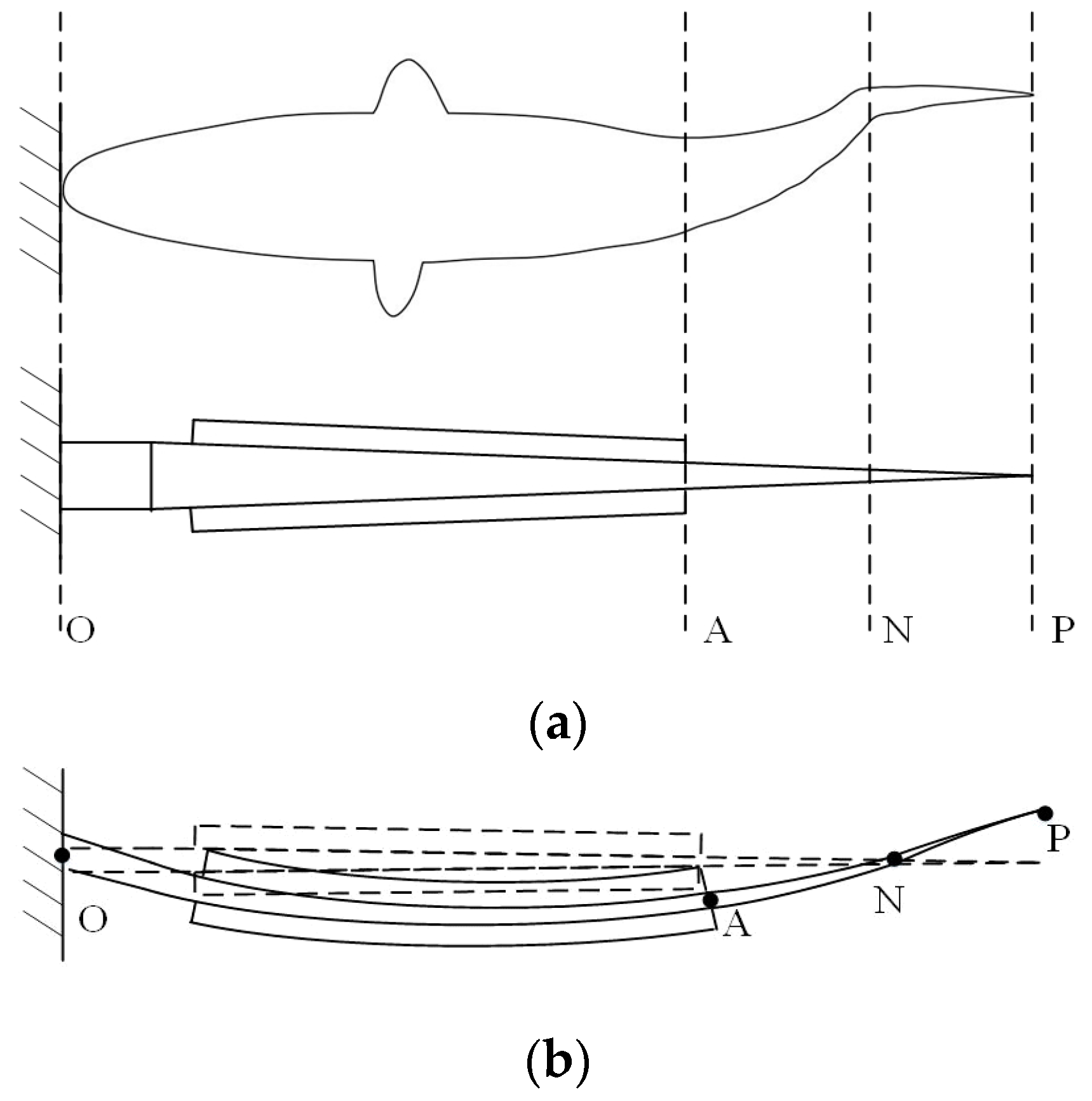
By observing the swimming characteristics of various fish species, it can be found that the swimming pattern of sturgeon can produce a high swimming speed (69–95 km/h). This species has high research value for our study. Tuna has the same typical swimming mode of sturgeon. Based on the swimming characteristics of tuna, their body can be divided into two parts: the trunk and the caudal fin, as illustrated in Figure 2a. When a tuna is in cruising mode, its movement resembles the second-order bending vibration of a swinging vibrator, as depicted in Figure 2b. This structural feature allows the trunk to undergo slight oscillations, which in turn induce significant oscillations in the caudal fin during swimming.
The large swing motion of the tail fin could produce a continuous driving force and create a cruising speed up to 55 mile/h (88 km/h) [20].
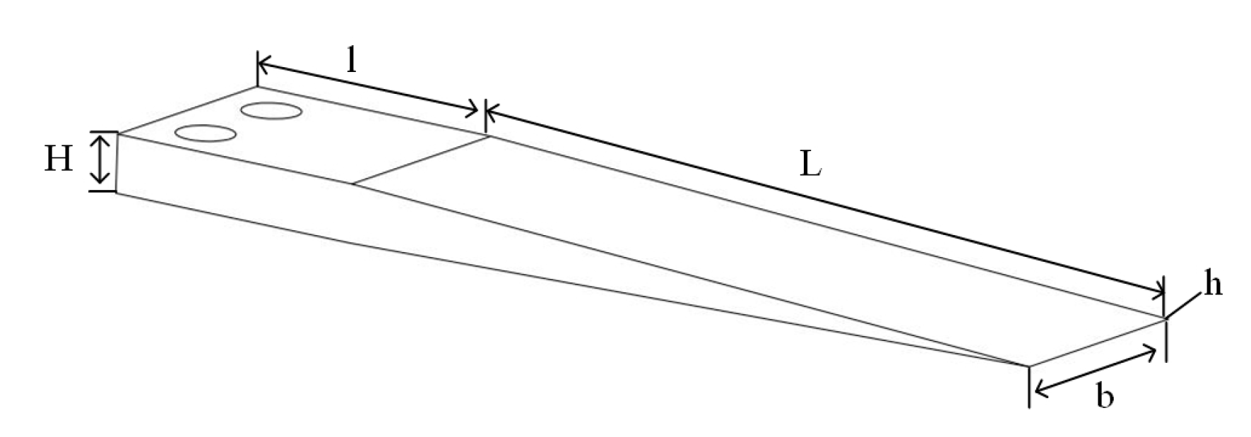
The piezoelectric vibrator is the core component of the piezoelectric pump, and the pump property depends largely on the performance of the vibrator. Inspired by the tuna body structure and swimming pattern, a vibrator substrate with a tapered cross-section was designed as shown in Figure 3, and the size parameter values of the vibrator are shown in Table 1. The material of the piezoelectric ceramic sheet is PZT-8 (piezoelectric lead zirconate titanate-8), and its parameters are shown in Table 2. The substrate of the vibrator was made of phosphor bronze. Its fixed end has the maximum thickness and contains a short flat section for mounting purposes. The thickness of the vibrator substrate is gradually reduced so as to mimic a fish tail. The tapered free end of the vibrator substrate (section AP in Figure 2a) functions as the tail fin of the fish. The tail fin and the vibrator substrate are built as an integrated structure, instead of welding a tail fin structure separately at the end of the vibrator, as shown in Figure 3 and Figure 4. The two piezoelectric ceramic sheets were pasted on the upper and lower sides of the substrate. Due to the inverse piezoelectric effect, the piezoelectric ceramic sheet alternately expands and contracts under the excitation of AC voltage, causing the bending oscillation of the piezoelectric vibrator. The oscillation of the double piezoelectric ceramic sheets is to imitate the muscle movement of the fish. The corresponding relationship between the piezoelectric vibrator and the fish-shaped body is shown in Figure 2, and the electrodes connection of the vibrator is shown in Figure 4.

4. Analysis of Pumping Principle

The piezoelectric vibrator in the flow field plays a major role to drive the fluid and form a unidirectional flow. Pumping fluid flow is the result of complex interactive mechanical, electrical, and hydraulic multi-physics fields. It is difficult to obtain an accurate analytical expression of the pumping flow. To investigate the main factors of the pumping flow and derive an approximate analytical expression and simplify the complexity of the research problem, this study only considered the effect of the piezoelectric vibrator on the fluid flow. Therefore, the piezoelectric vibrator is regarded as a whole body and defined as a rigid body. When driven by AC voltage, the piezoelectric vibrator swings around the fixed end in a sinusoidal pattern [21].
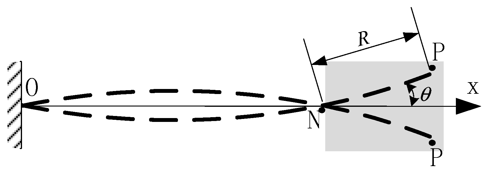
Experimental results demonstrate that when the piezoelectric vibrator operates in the second-order bending mode, it achieves a superior driving effect. As shown in Figure 5, point O represents the first node of the second-order mode, N is the second node, and T denotes the end of the vibrator. The ON segment undergoes vertical oscillations, which only induce up-and-down oscillations of the fluid within the pump chamber and do not contribute to unidirectional fluid flow. The only contribution to the unidirectional flow comes from the pitching motion indicated by the shaded region; hence, the analysis can be limited to the pitching motion within this shaded portion.
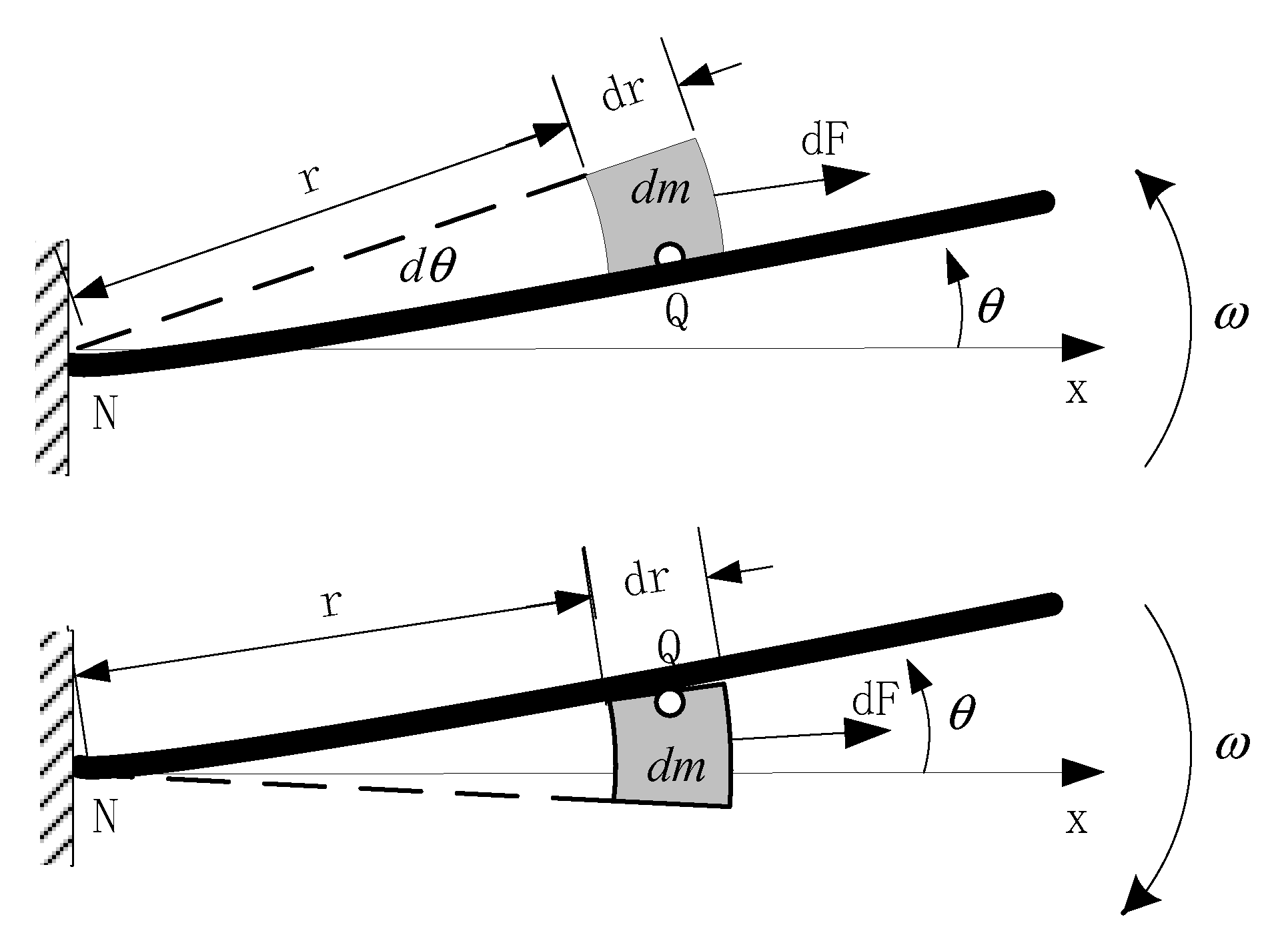
The fluid surrounding the vibrator undergoes arc swing motion under the influence of the vibrating vibrator, producing a motion away from point N along the vibrator direction due to inertial forces, as illustrated in Figure 6. Within the given coordinate system, assuming the vibrator begins oscillating at time t = 0 , starting from an initial angular position of θ = θ 0 , the angular displacement of the vibrator can be expressed as:
θ = θ 0 c o s 2 π f t
where f represents the vibration frequency of the vibrator, which is identical to the frequency of the applied excitation. θ 0 is the angular amplitude of the vibration, and t is time.
The circumferential velocity of a fluid particle can be expressed as:
v = r θ ˙ = r θ 0 2 π f s i n 2 π f t
The centrifugal force acting on a fluid particle at a given position is:
d F = ρ · b · θ 0 3 2 π f 3 s i n 3 2 π f t r 2 d r d t
where ρ is the density of water and b is the width of the vibrator.
Starting from time t = 0 , when the vibrator begins moving from its maximum negative angular displacement θ 0 , and reaching time s : 0 s 1 4 f . The increase in fluid momentum due to the vibrator’s action equals the momentum of the fluid leaving the pipeline:
P a d d = 0 s v ( t ) d m = 0 s v ( t ) A ρ v ( t ) d t = A ρ 0 s v 2 ( t ) d t
where v represents the velocity component of the fluid particle in the direction of the pump chamber and A is the cross-sectional area of the outlet pipe.
During the time interval 0 ~ s , the impulse experienced by the fluid along the direction of the pump chamber is given by:
I = ( c o s θ ) d F d t
Given that the value of θ is relatively small, it can be approximated as:
I = d F d t
By combining Equations (4) and (6), we obtain:
A ρ 0 s v 2 ( t ) d t = d F d t
ρ A v 2 s = d F = ρ · b · θ 0 3 2 π f 3 0 < r < R 0 < t s s i n 3 2 π f t d t r 2 d r = ρ · b · θ 0 3 2 π f 2 R 3 3 [ c o s 3 2 π f s 3 cos 2 π f s + 2 3 ]
where R represents the effective length of the portion of the vibrator undergoing pitching motion, as shown in Figure 5.
At time s , the instantaneous flow rate v s is:
v s = 1 A · b · θ 0 3 2 π f 2 R 3 3 [ c o s 3 2 π f s 3 cos 2 π f s + 2 3 ]
The volume of fluid pumped out during the time interval 0 ~ 1 4 f (one-quarter of a cycle) is:
V = 0 1 4 f v t d t · A = 2 π f θ 0 R A · b · θ 0 R 3 0 1 4 f [ c o s 3 2 π f s 3 cos 2 π f s + 2 3 ] d s
Finally, the volumetric flow rate of the pump per minute Q m i n is given by:
Q m i n = 480 π f 2 A · b · θ 0 3 R 3 3 0 1 4 f [ c o s 3 2 π f s 3 cos 2 π f s + 2 3 ] d s
According to Formula (11), the flow rate of the pump is related to the vibrator’s amplitude, frequency, length, and width and also related to the cross-sectional area of the outlet tube.

5. Simulation Analysis of Pumping Performance Based on Fluid–Solid Coupling

The flow rate of the piezoelectric pump is the result of the coupling effect of mechanical–electrical–hydraulic multi-physics [22,23,24]. To investigate the actual pattern of the flow field and study on the change law of fluid flow and its influencing factors, the multi-physical-fields coupling analysis software COMSOL Multiphysics 6.1 was used to carry out a fully coupling simulation analysis of the flow field in the piezoelectric pump with the tapered cross-sectional vibrator.

5.1. Coupling Simulation Model of the Piezoelectric Pump

A simulation model of the piezoelectric pump was established using a software COMSOL Multiphysics 6.1. The size of the pump chamber (Length × Width × Height) was set as 85 × 20 × 10 (mm). Both diameters of the inlet and outlet tubes were 5 mm, the fluid medium was water with a temperature of 20 °C under standard atmospheric pressure, density ρ = 998.2 kg/m3, and the dynamic viscosity was 1.003 × 10⁻³ kg/m∙s, the inlet of the pump chamber was set as the speed inlet, and the outlet was set as the 0 pressure outlet.
Simulating this fluid–solid coupling in COMSOL Multiphysics 6.1 is to reveal the interactions between the vibrator powered by electricity and the fluid. These interactions include electrostatic field, solid mechanics field, and laminar flow physical field in the current model, which correspond to the piezoelectric ceramic sheet, vibrator substrate, and fluid domain (water). Specifically, there is a piezoelectric coupling between the electrostatic field (piezoelectric ceramic sheet) and the solid mechanics field (vibrator substrate) and a fluid–solid coupling between the vibrator and the fluid domain (water). The electrostatic module of the piezoelectric ceramic sheet is considered as charge conservation. Thus, the external surface potential is V = V 0 s i n ( 2 π f t ) , where V 0 and f are the amplitude and frequency of the driving voltage, respectively. The contact surface between the ceramic sheet and the vibrator substrate is set as the ground boundary, and the contact surface between the piezoelectric vibrator and the fluid is the fluid–solid coupling boundary. The fixed end of the vibrator is a fixed constraint. The coupling interface of the piezoelectric effect is treated as the solid mechanical field and the electrostatic field; the fluid–solid coupling interface is considered as the laminar flow physical field and the solid mechanical field. The fluid domain is set as the dynamic mesh deformation domain. The mesh element type is selected as free tetrahedral mesh with a size range of 0.5–2 mm. The maximum element growth rate is 1.5, and the curvature factor is 0.4. The mesh model is shown in Figure 5.

5.2. Mesh Sensitivity Analysis

Mesh sensitivity was analyzed based on different numbers of mesh elements. As an example, the pump internal flow-field analysis was carried out with a mesh model as shown in Figure 7. This example included more than one different mesh density, and other conditions are the same. According to the results of the simulation as shown in Table 3 and Figure 7, when increasing the quantity of mesh elements or mesh density, the simulated flow rate decreased rapidly and then tended to steady when the number of mesh elements was greater than 30,000. When increasing mesh elements from 33,865 to 144,625, the simulated flow rate was relatively constant. This is the mesh sensitivity analysis.

5.3. Flow-Field Analysis of the Piezoelectric Pump

The second-order mode of the tapered cross-sectional vibrator is the closest to the swimming pattern of the fish, and the driving effect of the second-order bending vibration on the fluid is greater than other modes. Thus, to obtain the second-order vibration mode when simulating the fluid–solid two-way coupling, the amplitude of the driving AC voltage of the vibrator was set at 150 V, and the driving frequency was the second-order mode frequency of the vibrator, which means the boundary potential was V = 150 s i n ( 2 π f t ) , and the transient calculation step was 10−4 s, and the calculated total time was 0.015 s.
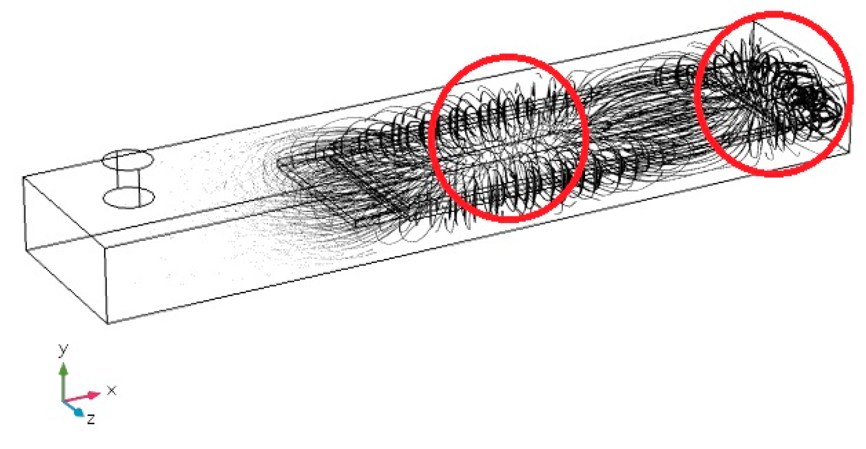
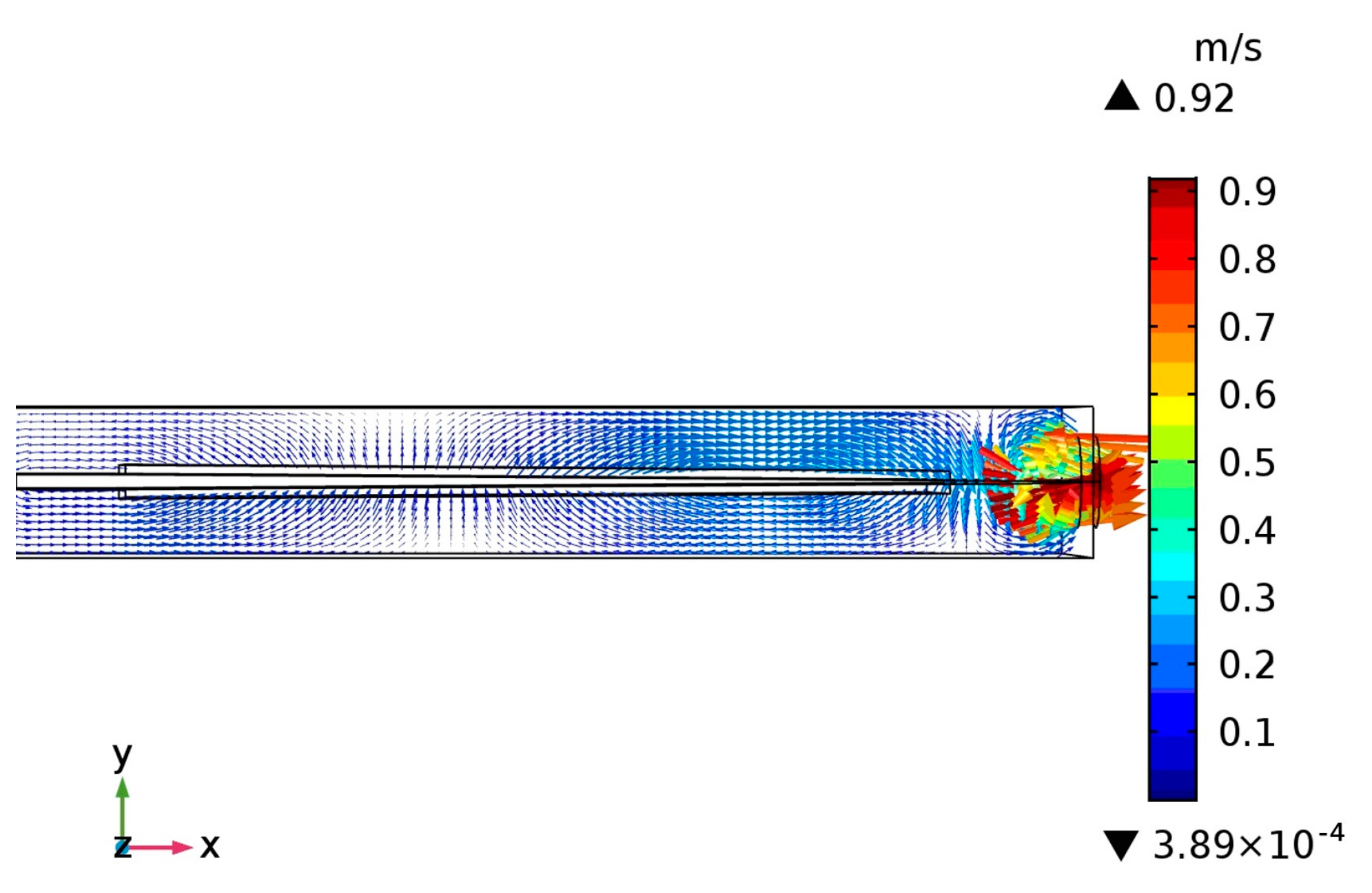
Simulation results can be seen from the fluid streamline diagram (Figure 8), which indicated that two fluid vortices were generated in the flow field around the vibrator. One field appeared in the two-thirds of the vibrator away from the fixed end, and the other appeared in the tail region, in the one-third area of the vibrator from the swing end. Comparing with the fluid velocity field diagram as showed in Figure 9, it can be seen that the fluid near the swing end has much higher velocity than that around the fixed end of the vibrator. This is basically consistent with the characteristics of tuna swimming discussed in Section 2 above. It is the continuous driving force produced by the large swing of the vibrator tail that drives the fluid to form unidirectional flow. It can be further inferred that near the second-order mode shape, there is a node on the tail of the vibrator as showed in Figure 10. The second-order mode is divided into two parts by the node N, where θ is the angle between the segment NP and the equilibrium position. The movement of the segment ON causes the fluid to oscillate in the y direction, but it contributes less for driving the fluid flowing in the x direction. On the contrary, the segment NP swings around the node N to drive the surrounding fluid flowing mainly in the direction of the X coordinate.
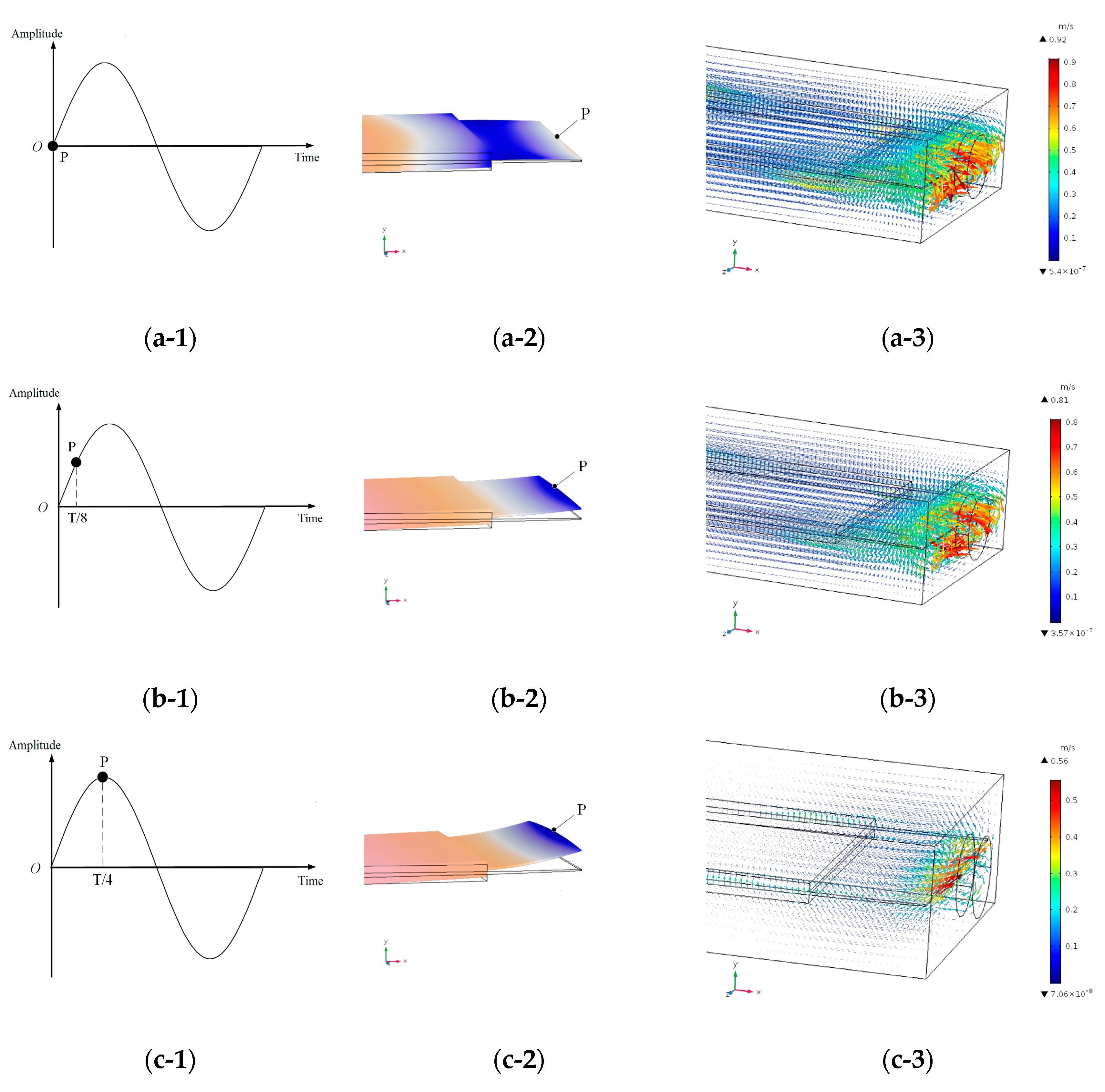
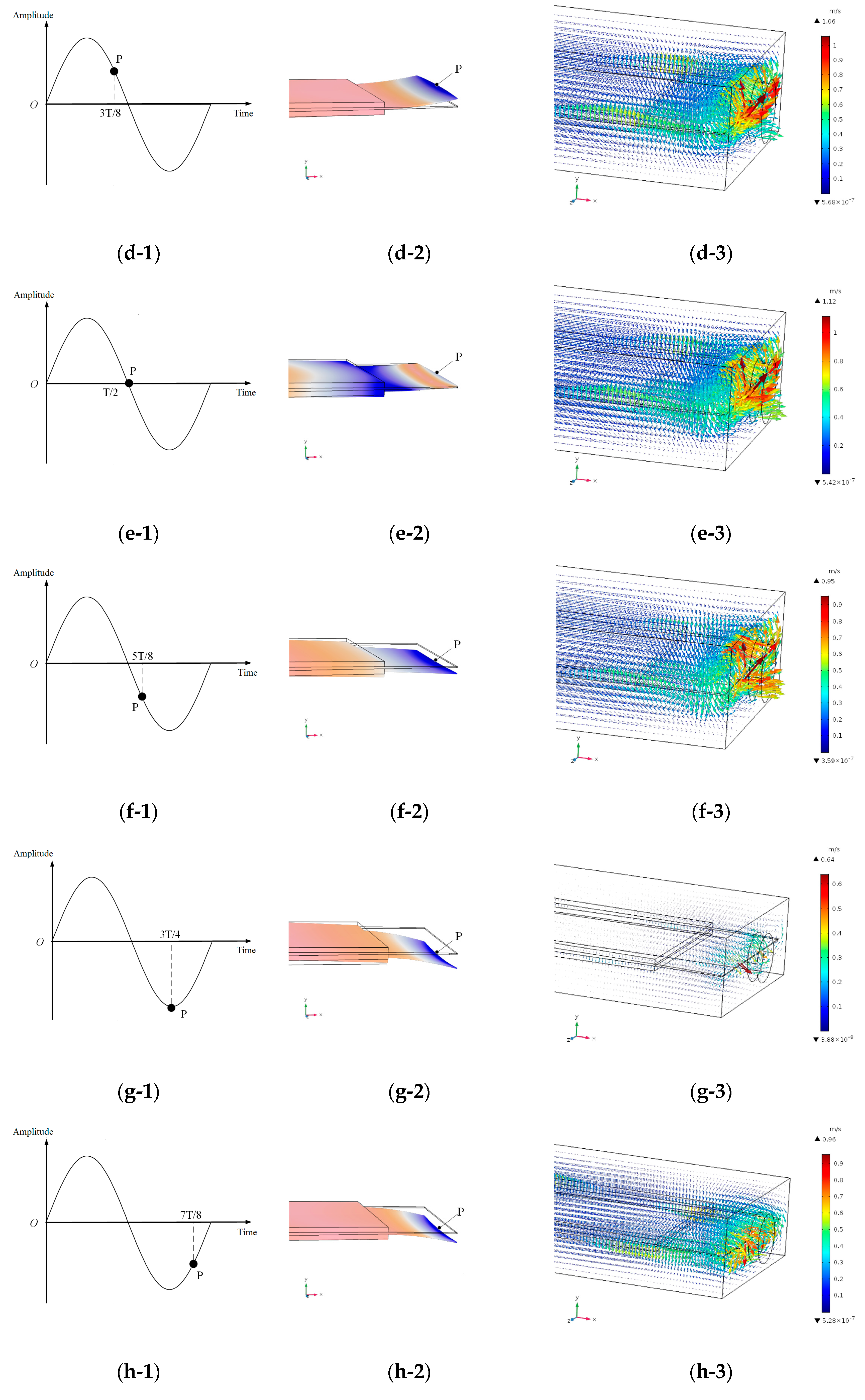
Figure 7 shows that there is an obvious fluid disturbance region in the flow field of the vibrator tail. In order to further analyze the actual pattern of the flow field, the following analysis was focused on the vibrator vibration and the flow field in the tail region and fluid velocity distribution during a typical vibration period T. The fluid velocity distribution at each typical time point is shown in Figure 11.
According to the fluid disturbance area of the flow field at the tail region in Figure 9, when the tail of the vibrator (or point P) moves to the position at time T/2 (as shown in Figure 11(e-1)–(e-3)), the fluid driven by the vibrator tail fin reaches the maximum velocity of 1.12 m/s. The angle θ between the NP and the equilibrium position is 0 at this time according to Figure 10, and the driving velocity of the NP on the surrounding fluid is the largest in the x direction, while the velocity component is 0 along the y direction; when the vibrator swings up and down from the equilibrium position, the angle θ gradually increases, which makes the driving effect of the NP on the surrounding fluid gradually decrease along the x direction, and the fluid velocity reduces; when the point P moves to the position at the times T/4 and 3T/4, the fluid velocities are the smallest, 0.56 m/s and 0.64 m/s, respectively. According to the vibration position of the vibrator at time T/4 and time 3T/4, the point P reaches the maximum displacement after going upward and downward (as shown in Figure 11(c-1)–(c-3) and (g-1)–(g-3)). At these two typical moments, the vibrator tail (or point P) begins to go backward, causing an instantaneous motion suppression, which leads to a decrease in the speed of fluid flow. The formation of pumping flow is caused by the vibrator driving the fluid continuously. The superposition of all the continuous fluid movement in the fluid domain forms a unidirectional flow from the inlet to the outlet. Based on the above analysis, it can be seen that the driving of the vibrator tail plays a major role of forming the pumping flow.
In the above analysis, there will be effects of gravity, but it is overall downward along the equilibrium position because of gravity influence, the amplitude of the vibrator is almost not affected, so the flow rate is almost not affected.
During the simulation analysis, the outlet flow rate was calculated. After the post-processing, the simulated flow rate of the piezoelectric pump was obtained. Theoretically, when the vibrator works at the second-order mode, it has good driving performance. Flow rates were simulated and calculated at different driving frequencies with the tapered cross-section vibrator. The driving frequencies were selected around the second-order mode frequency (588 Hz) of the vibrator, with a frequency range of 540–660 Hz. The pumping flow rates at different frequencies were obtained, as shown in Figure 12. Simulation results indicated that the pump reached its largest pumping flow rate near the driving frequency of 588 Hz.
The vibrator has the advantages of simple structure, good process performance, closer to the shape of biological fish body, and improved pumping performance. In the future, it will be widely used in agriculture drip irrigation, fruit tree spraying management, cooling and lubrication of precision equipment, and so on.

6. Experiment

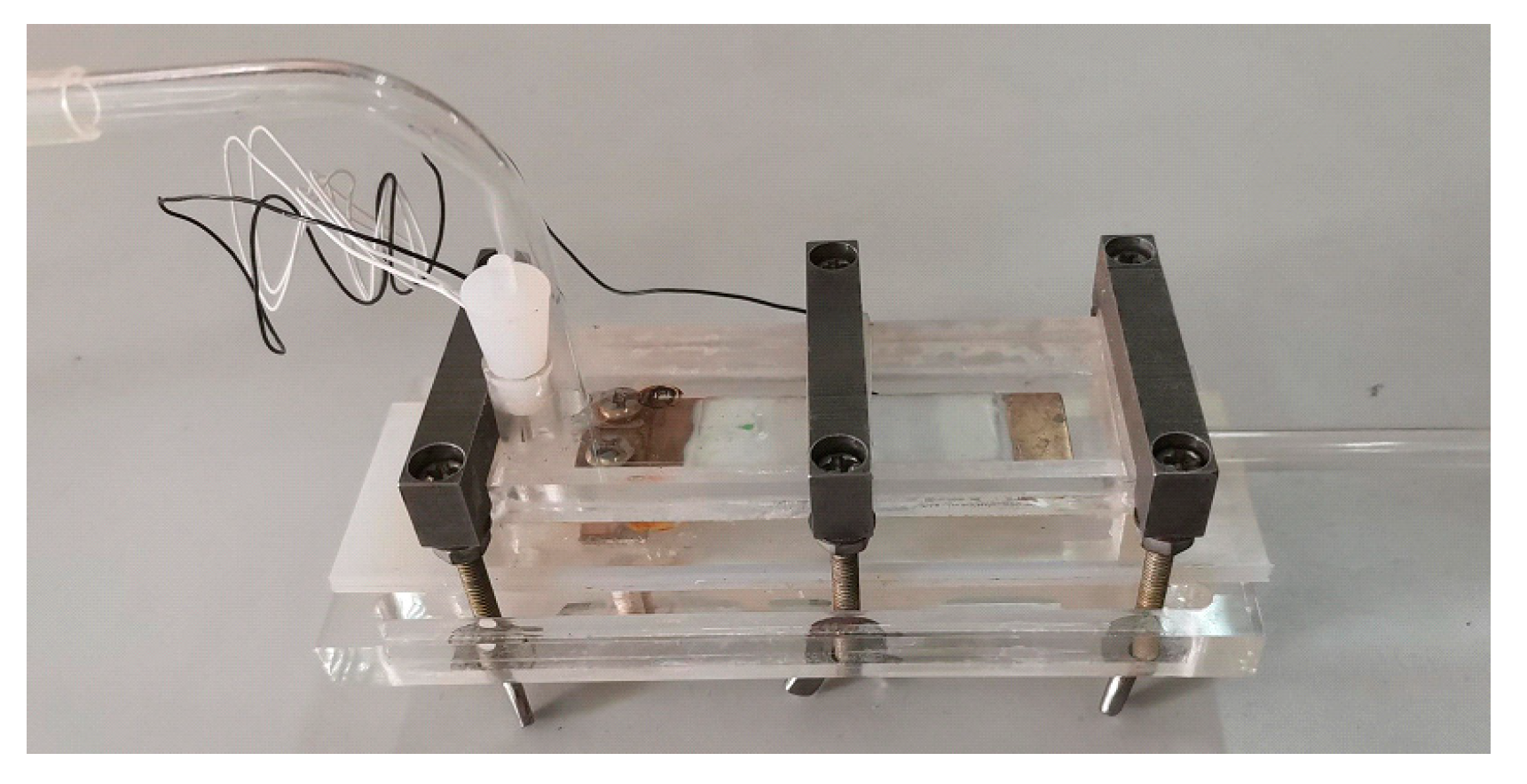
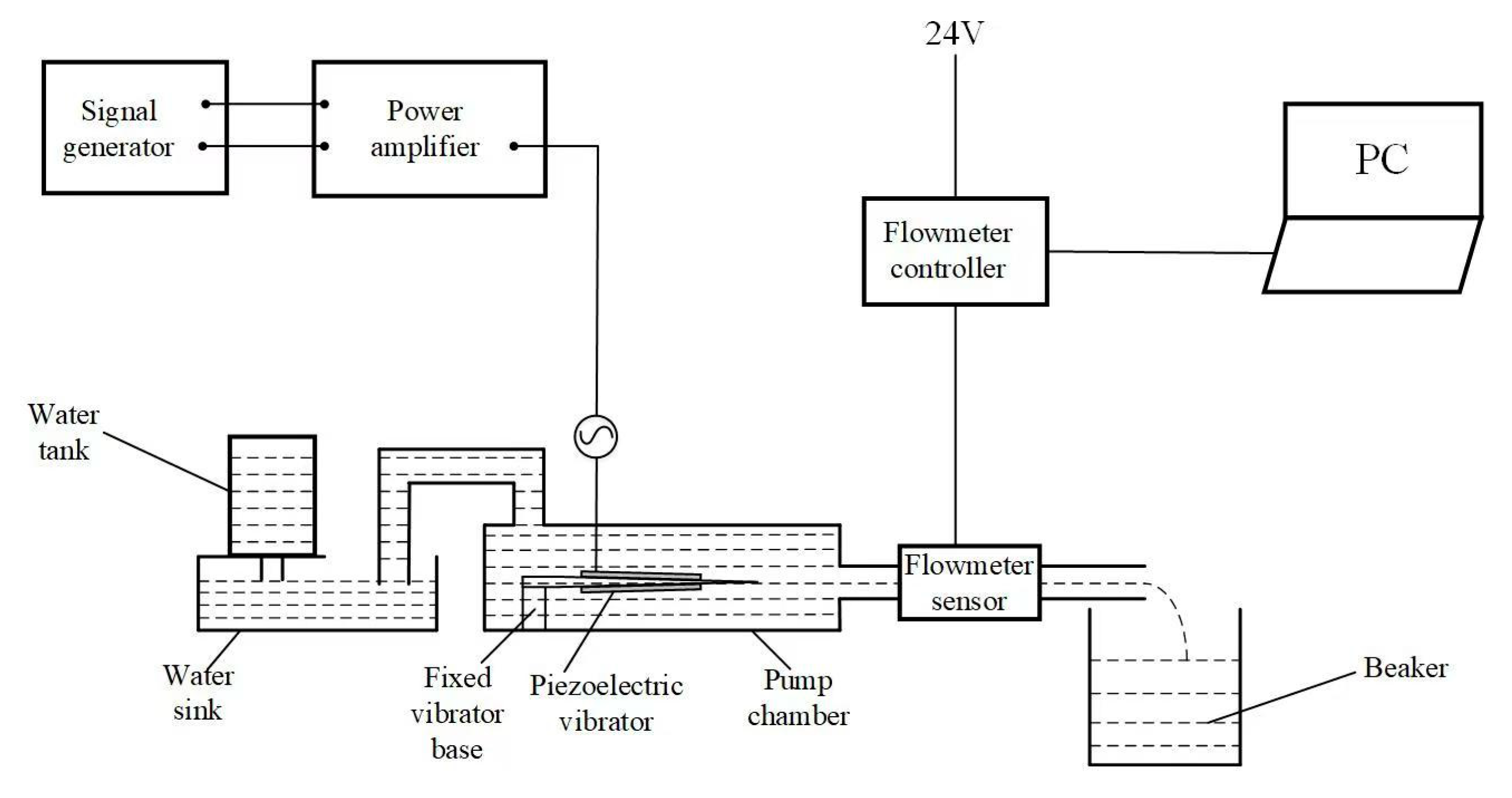
In order to test the pumping performance of the piezoelectric pump with a tapered cross-section vibrator, a prototype pump was made (Figure 13) and a flow rate testing system was built. The principle of the testing system is shown in Figure 14. During the experiment, the flow rate meter sensing head was installed at the outlet pipe of the piezoelectric pump, the power supply of the flowmeter controller was opened, and the piezoelectric pump chamber was filled with water to ensure that there were no bubbles in the pump chamber. The liquid level at the inlet and outlet of the piezoelectric pump was ensured to be consistent. Finally, the AC power supply of the piezoelectric vibrator was connected, and the piezoelectric pump worked. The controller performed A/D conversion and transmitted the test results to the PC end. The experiment was carried out at room temperature with water as the test medium.
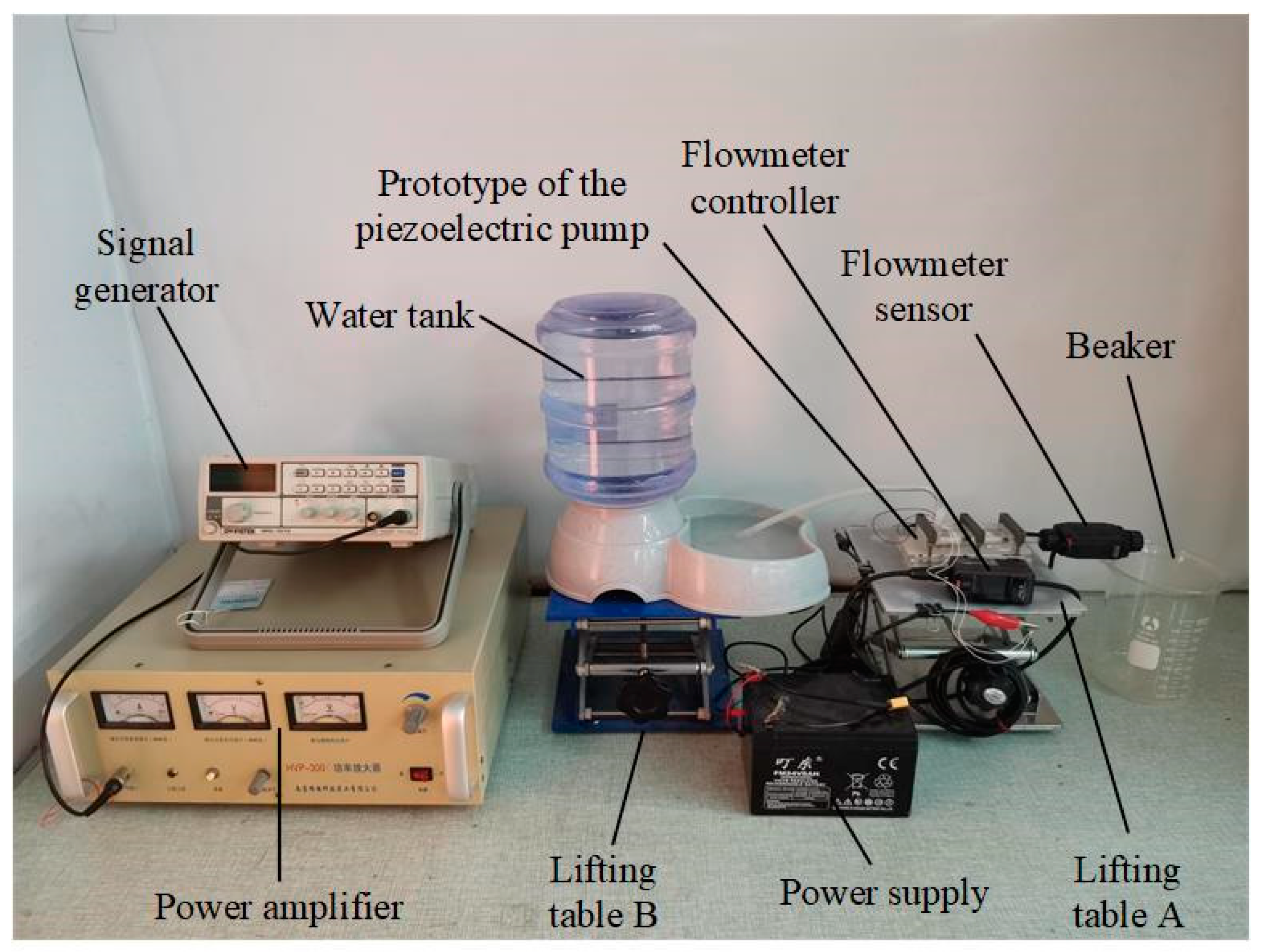
According to the principle of the testing system, a piezoelectric pump test platform was set up, as shown in Figure 15, and the test equipment mainly included: signal generator, power amplifier, water tank, piezoelectric pump, flow rate meter, power supply, and beaker. Among them, the signal generator and power amplifier provided the driving signal for the piezoelectric pump. The driving voltage of the pump was 150 V, which is the same with the driving voltage used in simulation; the water level at the pump inlet was kept constant by a water tank with an automatic water filling system. The heights of lifting table A and lifting table B were adjusted to ensure the water level in the flume of the water tank was consistent with that in the outlet tube. And the flow rate meter was used to monitor the pumping flow at the outlet.
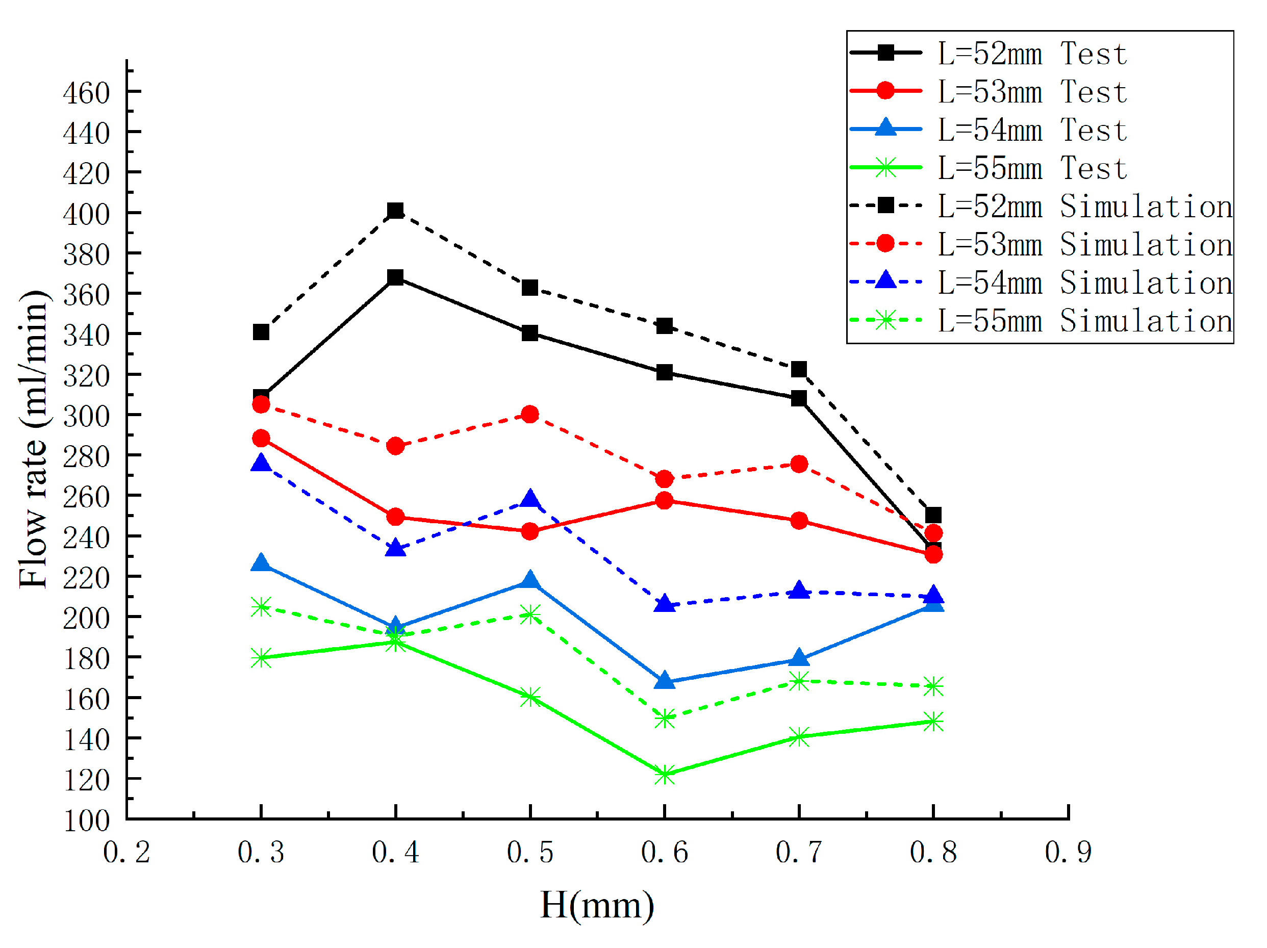
Based on experience, the working length size L and the fixed end thickness H of the vibrator have a crucial impact on pumping performance. With other sizes fixed, the vibrators were made with different L (52–55 mm) and different H (0.3–0.8 mm) size values. The pumping flow rate of the different size vibrators were tested at the driving voltage of 150 V and driving frequency of 588 Hz. The variation curves of simulation and test values are shown in Figure 16. It can be seen from the figure that the trend of simulation and test values was consistent. When L = 52 mm and H = 0.4 mm, the maximum values of simulation flow rate and test flow rate were obtained simultaneously.
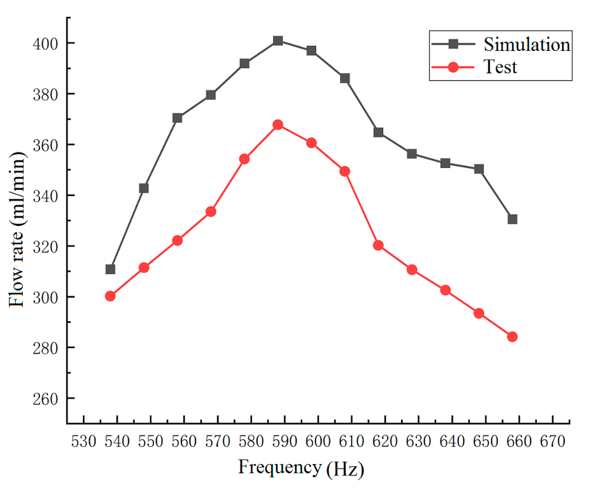
Further, a piezoelectric pump with the vibrator L of 52 mm and H of 0.4 mm, and all other sizes remaining the same, was used as the experimental prototype. The driving voltage was 150 V, and the driving frequency range was 540–660 Hz. The variation of pumping flow rate with different driving frequencies was tested and compared with the simulated flow rate. The results are shown in Figure 17, where these measured values are compared to the simulated pumping flow rates. It can be seen that the tested flow rate changes in the same trend as the simulated flow rates under different driving frequencies. The maximum flow rate values are both near the driving frequency of 588 Hz, which indicated that the fluid–solid coupling analysis could predict the working performance and changing rules of the piezoelectric pump and the piezoelectric vibrator. The maximum flow rate from the simulation was 400.8 mL/min, and the tested maximum flow rate was 367.7 mL/min. Under the same conditions, the simulated flow rate was greater than the tested flow rate, and the overall error was 9%.

7. Discussion

(1)
The main reasons for the errors between the simulation flow rate and test flow rate may include the following: (1) during the simulation, the fluid was an ideal fluid, and the surface of the vibrator was perfectly smooth. However, the vibrator used in the test was made as good as possible, but its surface still had certain roughness. The fluid around the vibrator actually may have large additional mass and additional damping, which could cause kinetic energy loss of the vibrator and then reduce the pumping flow. (2) During the simulation, the setting of the fluid–solid coupling field was under perfect conditions, but the actual test could be affected by many external factors, such as the ambient temperature change, the tightness of the pump chamber, and the resonance frequency drifts when the vibrator works in the water. (3) The limitations of the numerical model are that we are only considering the effect of the structure on the fluid, not considering the effect of the fluid on the structure, and not considering the viscosity of the fluid. The simulation flow rate is larger than the experimental flow rate because the model assumption has been idealized. All of these factors could cause fluctuations in the test flow rate.
(2)
The potential improvements and future research directions: (1) The tapered cross-sectional vibrator is more in line with the characteristics of a biological fish body. In future research, the driving mechanism can be further explored, the structure can be further optimized, and miniaturization and the driving efficiency can be further improved. (2) In terms of efficiency, due to the smooth transition of the tapered cross-section vibrator, compared with the welded vibrator, the efficiency has been significantly improved. In terms of durability, the tapered cross-section design solves the problem that the tail fin of the welded vibrator easily falls off and fatigue fractures and so on, greatly improving durability. (3) In the future, when miniaturization of the design occurs, the fluid–solid coupling model needs to be reconstructed because when scaled for smaller application, the influence of fluid viscosity force increases and the influence of inertia force of the vibrator decreases. (4) In the safe voltage range, the materials of the vibrator can work for a long time, and the persistent performance is good. It is not affected by different fluid environments, but different fluids have different viscosities, which will affect the resonant frequency of the vibrator. So, it is necessary to adjust timely the driving parameters of the vibrator.

8. Conclusions

The above research showed that for the complexity of the flow field in the pump chamber, the simulation based on multi-physical-fields coupling can accurately analyze the flow pattern and fluid velocity distribution in the pump chamber. Tests further verified that the pump had good fluid delivery performance. And the structure of the piezoelectric pump with a tapered cross-sectional vibrator integrates the vibrator base and the tail fin part, which effectively reduced the number of core components and simplified the processing technology. The conclusions of this study are summarized as follows:
(1)
According to the bionic principle of fish swimming, using the inverse piezoelectric effect of piezoelectric ceramics, the design of a valve-less piezoelectric pump with the tapered cross-section vibrator was proposed. The corresponding relationship between the piezoelectric vibrator and the fish-shaped body was given. And the approximate analytical expression of pumping flow rate was derived through theoretical analysis.
(2)
The flow field of the pump is simulated and analyzed based on the multi-physical-fields coupling with the software of COMSOL Multiphysics 6.1, and two vortices generated in the flow field have been discussed, which was consistent with the swimming characteristics of fish; for the obvious fluid disturbance area of the flow field around the vibrator tail region, the velocity change of the flow field was analyzed at each typical time point in a vibration period, and the simulated flow rate of the pump has been obtained after post-processing.
(3)
A prototype of the pump was made, and the performance tests were carried out. The results showed that the tested flow rate changes in the same trend as the simulated flow rate under different driving frequencies, and the overall error of the simulated flow rate relative to the tested flow rate was 9%. And the reasons for the error have been analyzed.

Author Contributions

Conceptualization, C.H. and X.H.; methodology, X.H.; software, W.J. and Q.Z.; validation, J.J. and X.H.; formal analysis, S.L.; investigation, W.J.; resources, Q.Z.; data curation, Q.Z.; writing—original draft preparation, C.H.; writing—review and editing, W.J.; visualization, S.L.; supervision, X.H.; project administration, J.J.; funding acquisition, C.H. All authors have read and agreed to the published version of the manuscript.

Funding

This research was funded by the National Natural Science Foundation of China (No: 31971801) and the Natural Science Foundation of Shandong Province of China (No: ZR2020ME252, ZR2020ME250).

Institutional Review Board Statement

Not applicable.

Informed Consent Statement

Not applicable.

Data Availability Statement

The data presented in this study are available on request from the first author. The data are not publicly available due to privacy.

Conflicts of Interest

The authors declare no conflicts of interest.

References

  1. Dereshgi, H.A.; Dal, H.; Yildiz, M.Z. Piezoelectric micropumps: State of the art review. Microsyst. Technol. 2021, 27, 4127–4155. [Google Scholar]
  2. Wu, X.; He, L.; Hou, Y.; Tian, X.; Zhao, X. Advances in passive check valve piezoelectric pumps. Sens. Actuators A Phys. 2021, 323, 112647. [Google Scholar]
  3. Huang, W.Q.; Lai, L.Y.; Chen, Z.L.; Chen, X.S.; Huang, Z.; Dai, J.T.; Zhang, F.; Zhang, J.H. Research on a piezoelectric pump with flexible valves. Appl. Sci. 2021, 11, 2909. [Google Scholar] [CrossRef]
  4. Yan, Q.; Yin, Y.; Sun, W.; Fu, J. Advances in Valveless Piezoelectric Pumps. Appl. Sci. 2021, 11, 7061. [Google Scholar] [CrossRef]
  5. COMSOL: Multiphysics Software for Optimizing Designs. Available online: https://www.comsol.com/ (accessed on 1 June 2020).
  6. He, L.; Zhao, D.; Li, W.; Xu, Q.; Cheng, G. Performance analysis of valveless piezoelectric pump with dome composite structures. Rev. Sci. Instrum. 2019, 90, 065002. [Google Scholar] [PubMed]
  7. Zeng, D.; Chen, Y. High-Order Modal Shape Measurement of Centrifugal Impeller Blade by Using Marco Fiber Composite. J. Propuls. Technol. 2020, 41, 1612–1620. [Google Scholar]
  8. Woo, J.; Sohn, D.K.; Ko, H.S. Performance and flow analysis of small piezo pump. Sens. Actuators A Phys. 2020, 301, 111766. [Google Scholar]
  9. Dong, J.S.; Cao, Y.; Chen, Q.Q.; Wu, Y.; Liu, R.G.; Liu, W.S.; Yang, Y.; Yang, Z.G. Performance of single piezoelectric vibrator micropump with check valve. J. Intell. Mater. Syst. Struct. 2020, 31, 117–126. [Google Scholar]
  10. Wang, X.N.; Zhang, Y.J.; Zhuang, J.; Wu, D.M. Investigation and development of micropump. Fluid Mach. 2010, 38, 32–37. [Google Scholar]
  11. Yu, J.Q. Theoretical and Experimental Research on Jetting Valveless Piezoelectric Pump. Master’s Thesis, Jilin University, Changchun, China, 2005. [Google Scholar]
  12. Jiao, X.W.; Huang, W.Q.; Zhao, C.S. Development and application of piezoelectric pump technology. Micromotors 2005, 5, 66–69. [Google Scholar]
  13. Huang, J.; Zhang, J.H.; Wang, S.Y. Theory and experimental verification on valveless piezoelectric pump with multistage Y-shape tubes. Opt. Precis. Eng. 2013, 21, 423–430. [Google Scholar]
  14. Wu, B.D.; Li, J.; Cheng, G.M.; Yang, Z.G.; Feng, S.L.; Zeng, P. A preliminary study on plate valveless piezoelectric pump. Piezoelectric Acoustooptic 2001, 4, 256–258. [Google Scholar]
  15. Leng, X.F.; Zhang, J.H.; Jiang, Y. Theory and experimental verification of spiral flow tube-type valveless piezoelectric pump with gyroscopic effect. Sens. Actuators A Phys. 2013, 195, 1–6. [Google Scholar]
  16. Leng, X.F.; Zhang, J.H.; Jiang, Y.; Wang, S.Y.; Zhao, C.S. Simulation analysis and experimental verification of spiral-tube-type valveless piezoelectric pump with gyroscopic effect. Chin. J. Mech. Eng. 2014, 27, 822–829. [Google Scholar]
  17. Pires, R.F.; Vatanabe, S.L.; De Oliveira, A.R. Water-cooling system using a piezoelectrically actuated flow pump for a medical headlight system. In Industrial and Commercial Applications of Smart Structures Technologies; SPIE: Bellingham, WA, USA, 2007; Volume 6527, pp. 1–11. [Google Scholar]
  18. De Lima, C.R.; Vatanabe, S.L.; Choi, A. A biomimetic piezoelectric pump: Computational and experimental characterization. Sens. Actuators A Phys. 2009, 152, 110–118. [Google Scholar]
  19. Hu, X.Q. Dynamics Analysis and Experimental Study on Nonrotating and Non-Volumetric Type Valveless Piezoelectric-Stack Pump. Ph.D. Thesis, Nanjing University of Aeronautics and Astronautics, Nanjing, China, 2012. [Google Scholar]
  20. Insha, A.T.; Azmin Shakrine, M.R.; Mohammad, Z.; Kamarul, A.A. Hydrodynamics of Bluefin Tuna—A Review. J. Adv. Res. Fluid Mech. Therm. Sci. 2019, 64, 293–303. [Google Scholar]
  21. Hu, X.Q.; Zhang, J.H.; Huang, Y.; Xia, Q.X.; Huang, W.Q.; Zhao, C.S. Principle and Experimental Verification of Caudal-fin-type Piezoelectric-stack Pump with Variable-cross-section Oscillating Vibrator. Chin. J. Mech. Eng. 2012, 25, 128–136. [Google Scholar]
  22. Zhu, Y.C.; Liu, C.; Song, Y.Z.; Chen, L.; Jiang, Y.L.; Wu, C.W. Research on an axial-mounted dual magneto strictive material rods-based electro-hydrostatic actuator. J. Intell. Mater. Syst. Struct. 2022, 33, 330–341. [Google Scholar]
  23. Huang, J.; Gong, J.Q.; Wang, L.; Affane, H.; Zhang, Q.; Zhang, J.H. Optimal design of fluidic diode for valveless piezoelectric pump based on entropy production theory. Sens. Actuators A Phys. 2023, 356, 114342. [Google Scholar]
  24. Pan, Q.S.; Jiang, H.Y.; Zhang, Y.F.; Li, R.J.; Huang, B.; Huang, Q.X. Development of a novel valve-based piezoelectric ultrasonic pump using a Langevin vibrator. Smart Mater. Struct. 2022, 31, 065026. [Google Scholar]
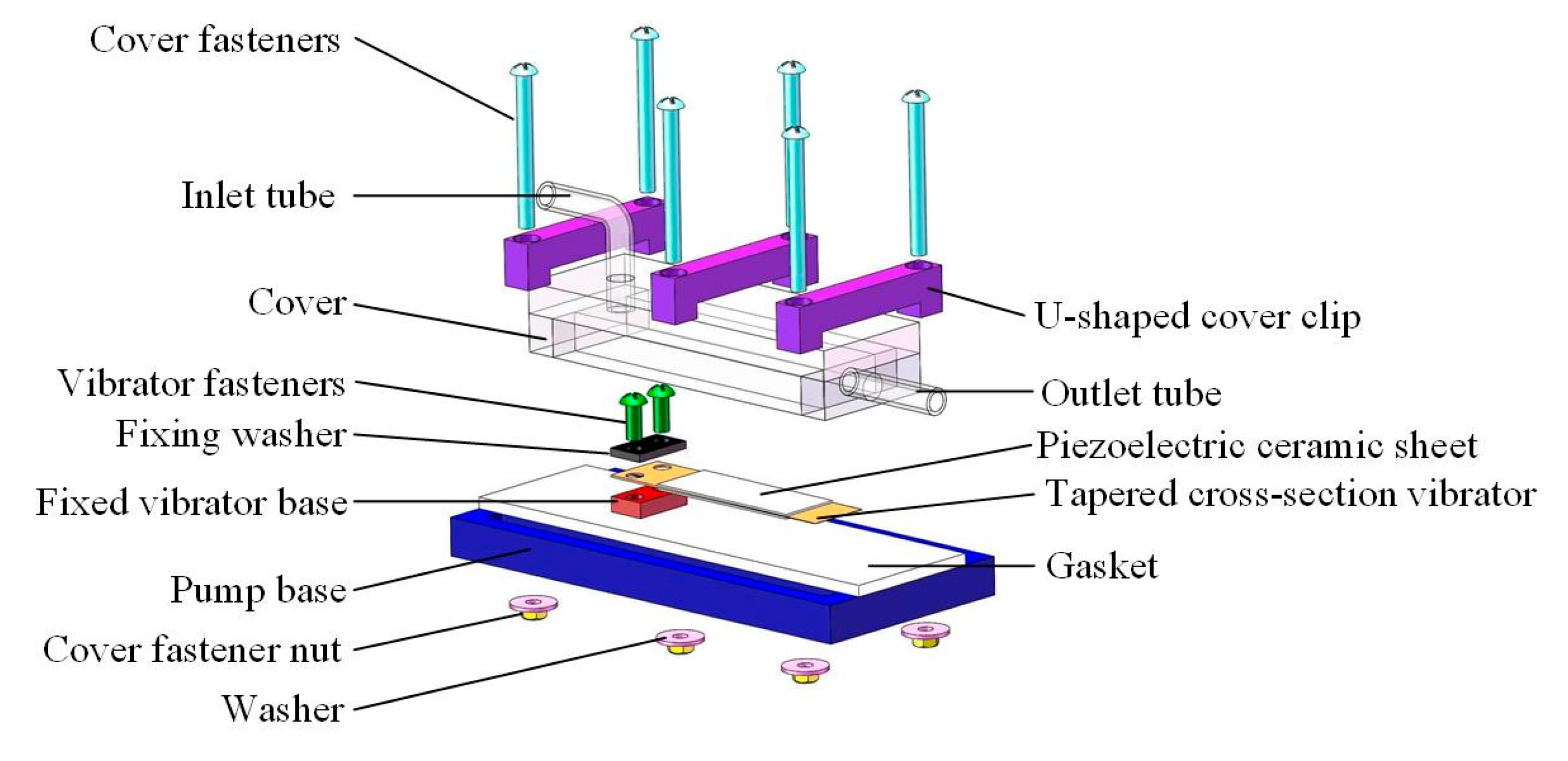
Figure 1. Structure of the piezoelectric pump.
Applsci 14 07418 g001
Figure 2. Bionic contrast diagram of the tapered cross-section vibrator. (a) Schematic diagram of the correspondence relationship between the piezoelectric vibrator and the fish-shaped body. (b) Vibration mode of the vibrator.
Applsci 14 07418 g002
Figure 3. Schematic diagram of the tapered cross-section vibrator substrate.
Applsci 14 07418 g003
Figure 4. Structure of the tapered cross-section vibrator.
Applsci 14 07418 g004
Figure 5. Simplified model of the pump vibrator.
Applsci 14 07418 g005
Figure 6. Centrifugal force on a fluid particle.
Applsci 14 07418 g006
Figure 7. Mesh model of the piezoelectric pump.
Applsci 14 07418 g007
Figure 8. Fluid streamline diagram in the pump chamber (the vortices are marked by red circles).
Applsci 14 07418 g008
Figure 9. Fluid velocity field in the pump chamber.
Applsci 14 07418 g009
Figure 10. Schematic diagram of the vibrator node.
Applsci 14 07418 g010
Figure 11. Fluid velocity distribution at the vibrator tail region during period T. (a-1) Amplitude curve of point P. (a-2) Vibrator tail position at the beginning. (a-3) Fluid velocity distribution at the beginning. (b-1) Amplitude curve of point P. (b-2) Vibrator tail position at T/8. (b-3) Fluid velocity distribution at T/8. (c-1) Amplitude curve of point P. (c-2) Vibrator tail position at T/4. (c-3) Fluid velocity distribution at T/4. (d-1) Amplitude curve of point P. (d-2) Vibrator tail position at 3T/8. (d-3) Fluid velocity distribution at 3T/8. (e-1) Amplitude curve of point P. (e-2) Vibrator tail position at T/2. (e-3) Fluid velocity distribution at T/2. (f-1) Amplitude curve of point P. (f-2) Vibrator tail position at 5T/8. (f-3) Fluid velocity distribution at 5T/8. (g-1) Amplitude curve of point P (g-2) Vibrator tail position at 3T/4 (g-3) Fluid velocity distribution at 3T/4. (h-1) Amplitude curve of point P. (h-2) Vibrator tail position at 7T/8. (h-3) Fluid velocity distribution at 7T/8. (i-1) Amplitude curve of point P. (i-2) Vibrator tail position at T. (i-3) Fluid velocity distribution at T.
Applsci 14 07418 g011aApplsci 14 07418 g011bApplsci 14 07418 g011c
Figure 12. Flow rate of simulation.
Applsci 14 07418 g012
Figure 13. Prototype of the piezoelectric pump.
Applsci 14 07418 g013
Figure 14. Schematic diagram of flow test.
Applsci 14 07418 g014
Figure 15. Pump flow test.
Applsci 14 07418 g015
Figure 16. Test–simulation flow rate contrast.
Applsci 14 07418 g016
Figure 17. Flow rate comparison result between simulation and test.
Applsci 14 07418 g017
Table 1. The dimensions of the vibrator.
ParameterValue (mm)
H0.3–0.8
h0.1
l15
L52–55
b16
Length of the piezoelectric ceramic sheet44
Width of the piezoelectric ceramic sheet16
Thickness of the piezoelectric ceramic sheet0.5
Table 2. The piezoelectric ceramic sheet PZT-8 parameters.
ParameterValue
Relative dielectric constant ε 1.85 × 10 3
Piezoelectric coefficient d 33 2.25 × 10 10 (C/N)
Capacitance C 1.608 × 10 6 (F)
Table 3. Mesh sensitivity analysis data.
Simulation NumberMesh Element QuantitySimulation Flow Rate Q (mL/min)
18356653
215,783557
326,642419
433,865400
547,231402
664,724 398
7144,625 401
Disclaimer/Publisher’s Note: The statements, opinions and data contained in all publications are solely those of the individual author(s) and contributor(s) and not of MDPI and/or the editor(s). MDPI and/or the editor(s) disclaim responsibility for any injury to people or property resulting from any ideas, methods, instructions or products referred to in the content.