Article

Analytical Model of Mechanical Responses of Circular Tunnels Considering Rheological Behavior of Surrounding Rock and Functionally Graded Lining

Bridge and Tunnel Research Center, Research Institute of Highway Ministry of Transport, Beijing 100088, China
*
Author to whom correspondence should be addressed.
Appl. Sci. 2024, 14(17), 7434; https://doi.org/10.3390/app14177434 (registering DOI)
Submission received: 13 July 2024 / Revised: 5 August 2024 / Accepted: 6 August 2024 / Published: 23 August 2024

Abstract

:
The rock–lining interaction significantly affects the stability and safety of a tunnel in service. In this study, a mechanical model is proposed to explore the rock–lining interaction under hydrostatic pressure. The model takes into account the alterable mechanical property (such as the elastic modulus) of the lining in the rheological rock mass, which may be subjected to inner surface pressure along the radial direction of the highway tunnel. The alterable elastic modulus is assumed as a power function of the radius. The analytical solutions of this model are first verified by comparison with existing solutions and corresponding results are obtained by numerical simulation. Then, systematic parametric investigations are carried out to analyze the influence of the main model parameters on the radial deformation of the rock–lining interface and the normalized supporting pressure provided by the lining. The research conclusions obtained by this study can offer some valuable references for the safety evaluation of a tunnel in service.

1. Introduction

Tunnel engineering is one of the primary infrastructure projects in the road, railway, rail traffic, mining engineering, and military sectors [1,2,3,4,5]. Tunnel construction inevitably affects the stress state of the surrounding rock. Tunnel lining, one of the major support structures of a tunnel project, plays a crucial role in the tunnel’s whole life [6,7,8]. The stability and safety of a tunnel in service are jointly controlled by the conditions of surrounding rock and lining. Therefore, research on rock–lining interaction is of great significance for evaluating the tunnel’s safety throughout its lifespan.
The changes in a tunnel wall’s deformation over time are closely linked to the time-dependent characteristics of the surrounding rock caused by tunnel excavation [9,10,11]. The time-dependent characteristics of the rock, also named its rheological behavior, have been thoroughly investigated by a series of rheological experiments on soft rock. The results showed that 30–70% of the total deformation is caused by the rheological behavior of the rock [12,13,14]. Additionally, due to the rheological behavior of the rock mass, the deformation of the surrounding rock and the pressure acting on the lining increase with service time, as observed in many actual projects such as the Ureshino tunnel [15] in Japan, the Lyon–Torino Base tunnel [16] in Italy and France, the Shibli tunnel [17] in Iran, Baijiao coal mine [3], the Minxian tunnel [18], and the Muzhailing tunnel [19] in China. Researchers have studied the rock–lining interaction and considered the surrounding rock’s rheological behavior using various methods, such as field monitoring [20,21], model experiments [22,23], numerical simulations [24,25], and theoretical analyses [26,27].
Tunnel excavation is a three-dimensional problem, especially around the tunnel cutting face. To simplify this problem in the theoretical analysis, the concept of fictitious support pressure has been proposed by many researchers [28,29,30]. After the fictitious support pressure is imposed on the tunnel wall, the three-dimensional problem of the tunnel face can be transformed into a two-dimensional one [31,32], allowing for easier analytical solutions. These solutions take into account the mechanical responses of the rock–lining interface during excavation and consider different rheological models. For example, Chu et al. [10] presented analytical models to investigate the mechanical behavior of the rock–lining interface during tunnel excavation, taking into account both the tunnel face effect and the rheological behavior of the rock mass. Kargar [33] deduced a viscous elastic–plastic solution to explore the stress-displacement distribution around unlined and lined tunnels, considering the tunnel face effect. However, there are limited studies on how the lining affects the rock–lining interaction after installation when subjected to radially inner surface pressure.
In tunnel projects, such as water and high-speed railway tunnels, the lining is subjected to inner surface pressures in the radial direction after tunnel construction. Based on the complex variable method, closed-form solutions have been proposed to explore the stress-displacement field around a circular tunnel whose lining is under hydrostatic pressure and thus under a radially inner surface pressure. However, the rheological behavior of the rock mass is not considered in these solutions [34,35,36].
When analyzing the rock–lining interaction, the lining is typically assumed to consist of a homogeneous and isotropic material. This assumption, which is incompatible with the actual conditions, certainly affects the analytical results of the rock–lining interaction.
To address this gap and analyze the mechanical responses of the rock–lining interface under hydrostatic pressure, a mechanical model is proposed in this paper that takes into account both the change of the mechanical property (such as the elastic modulus) of the lining subjected to inner surface pressure along the radial direction, and the rheological behavior of the rock mass. The highlight of this paper is that the mechanical property of the lining is a function of the radial coordinate instead of being constant. Firstly, the proposed mechanical model is verified by comparing it with an existing analytical one, as well as comparing its analytical solutions with the results of a numerical simulation. Then, systematic parametric analyses are conducted to study the influence of the model parameters on the radial deformation of the rock–lining interface and the normalized supporting pressure provided by the lining.

2. Problem Statement

This study aims to study the interaction between the surrounding rock and the lining subjected to inner surface pressure in the radial direction under hydrostatic pressure. The plan sketch of the calculation model is shown in Figure 1. The assumptions of this study are the following:
(1)
The horizontal and vertical pressure are equal.
(2)
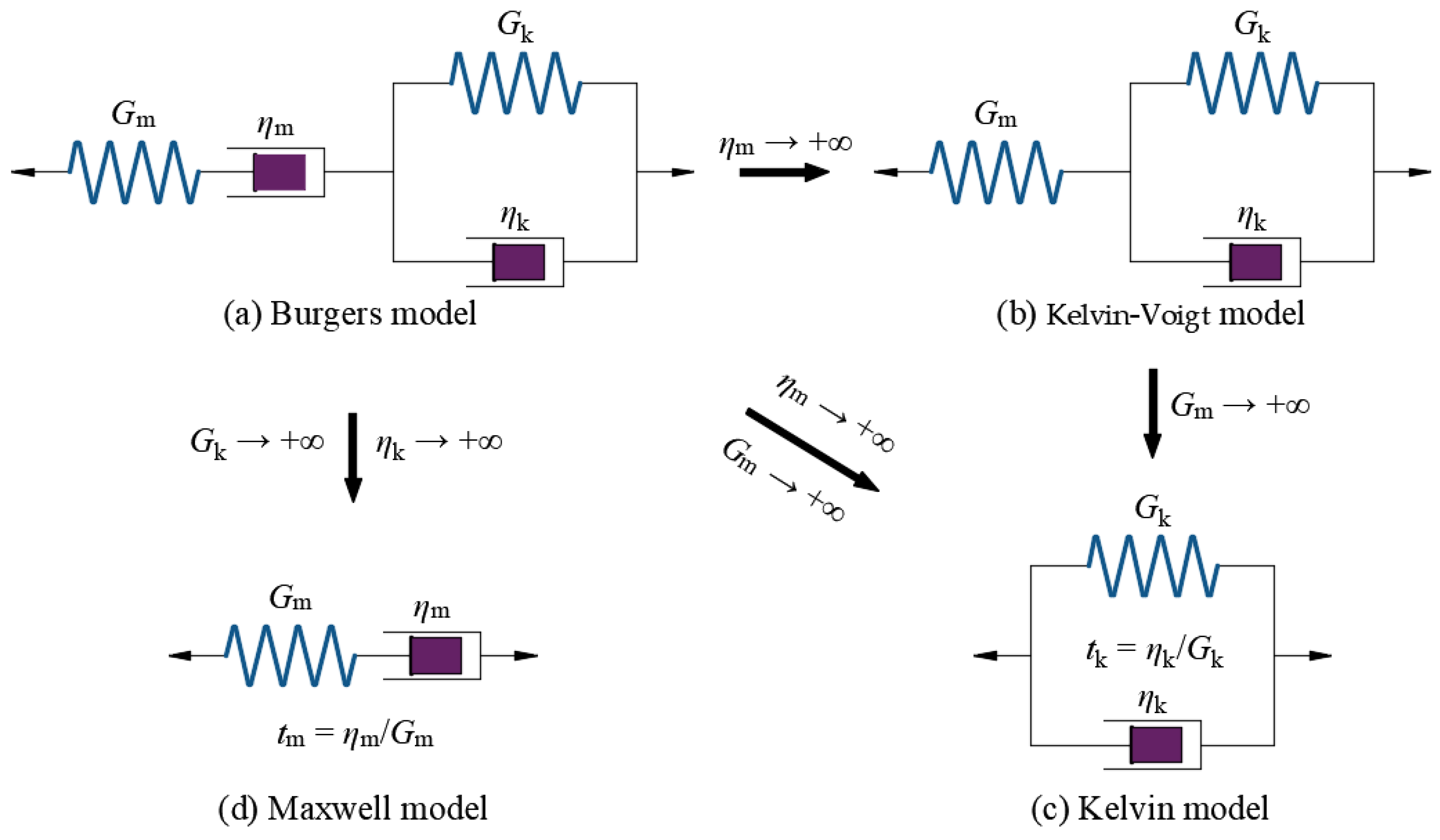
The rock mass is a homogeneous, isotropic, and viscoelastic material [10].
(3)
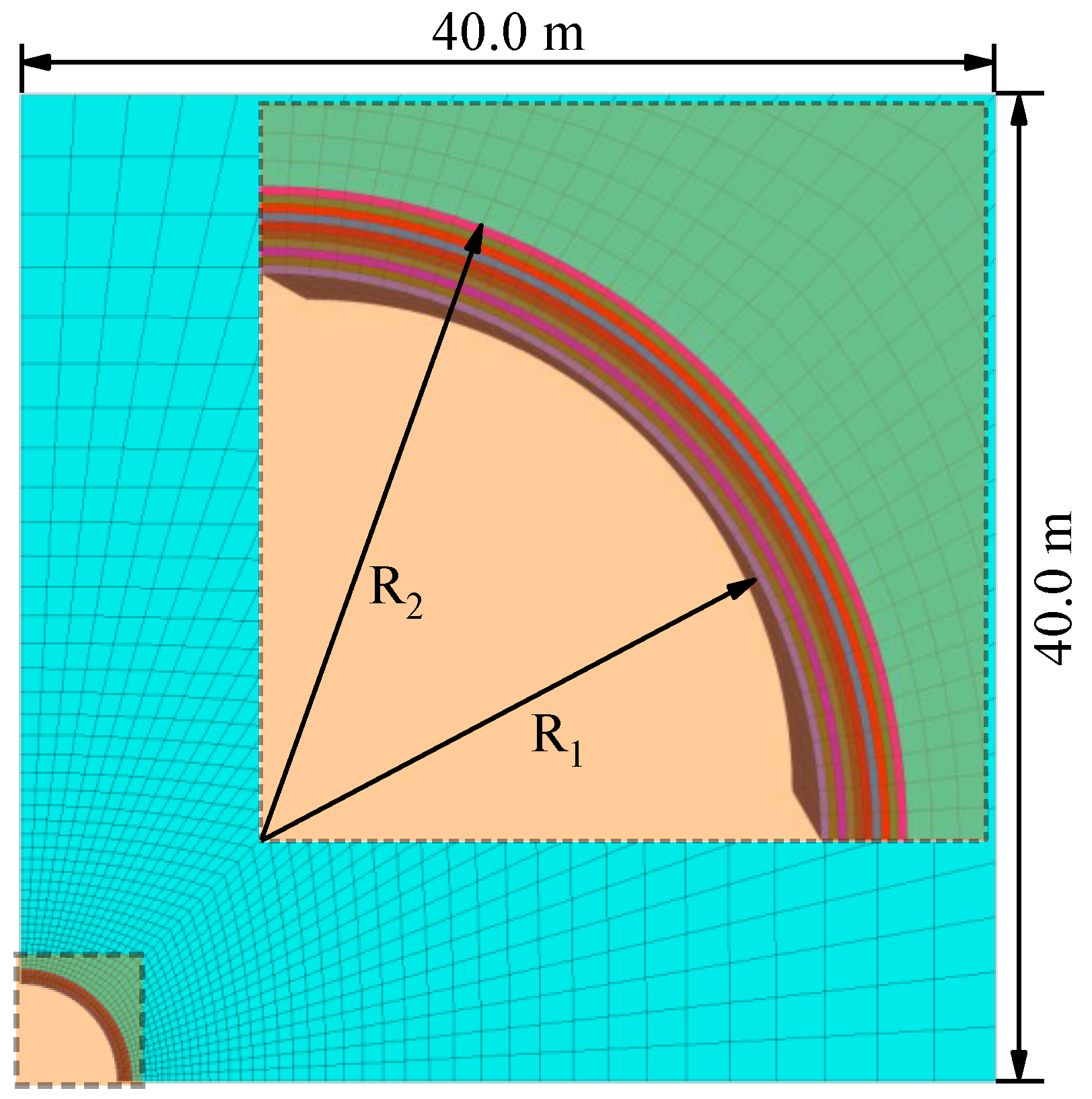
The excavation radius of the circular tunnel is R2.
(4)
The lining is an inhomogeneous, isotropic, and elastic material.
(5)
The inner and outer radii of the lining are R1 and R2, respectively.
(6)
The thickness of the lining is d.
(7)
The mechanical property (such as elastic modulus) of the lining varies only along the radial direction as a power function.
(8)
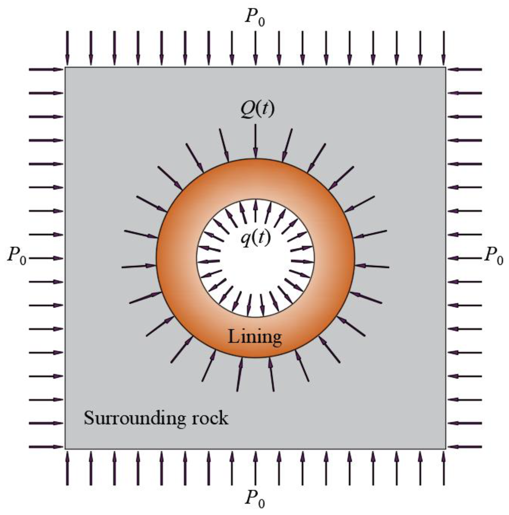
The inner surface of the lining is subjected to the pressure q(t) in the radial direction.
The Burgers model [37] is selected to describe the rheological behavior of the rock mass in this paper. The Burgers model is a comprehensive model that includes both the Maxwell and Kelvin models in series, as shown in Figure 2. Gm and ηm are the shear modulus and viscosity of the Maxwell model, respectively; Gk and ηk are the shear modulus and viscosity of the Kelvin model, respectively; and tm and tk are the relaxation and retardation times of the Maxwell and Kelvin models, respectively. When the dashpot element of the Maxwell model is ignored (ηm → +∞), the Burgers model is transformed to the Kelvin–Voigt model. When both spring and dashpot elements of the Maxwell model are ignored (Gm/ηm → +∞), the Burgers model is transformed to the Kelvin model. When both spring and dashpot elements of the Kelvin model are ignored (Gk/ηk → +∞), the Burgers model is transformed to the Maxwell model. The behaviors of the initial instantaneous strain, subsequent transient creep, and final steady creep of the Burgers model are controlled by the spring and dashpot elements of the Maxwell model, and the spring and dashpot elements of the Kelvin model [38].
The volumetric deformation of the rock is only elastic dilation under hydrostatic stress, and its rheological behavior is mainly affected by the deviatoric stress. Therefore, the stress and strain of the rock can be decomposed as follows:
σ i j R = δ i j σ k k R 3 + s i j R ε i j R = δ i j ε k k R 3 + e i j R
where σRij and εRij are the stress and strain tensors of the rock, respectively; sRij and eRij are the deviatoric stress and strain tensors of the rock, respectively; σRkk and εRkk are the volumetric stress and strain of the rock, respectively; and δij is the Kronecker delta.
The constitutive equation of the integral form of the Burgers model can be expressed as follows:
e i j R = J ( t ) d δ i j R J ( t ) = 1 2 G m + t 2 η m + 1 2 G k ( 1 e t / t k ) ε i i R = σ i i R / 3 K R
where J(t) is the creep compliance of the Burgers model; the asterisk ‘*’ denotes the convolution algorithm; and KR is the bulk modulus of the rock. An example of the convolution algorithm [39] is given as follows:
g 1 ( t ) d g 2 ( t ) = g 1 ( t ) g 2 ( 0 ) + 0 t g 1 ( t ξ ) g 2 ( ξ ) ξ d ξ
The elastic modulus and Poisson’s ratio are commonly used in the mechanical analysis of the lining. As the influence of the spatial variation of Poisson’s ratio on the practical significance of the actual engineering is much smaller than that of the elastic modulus, we assume that the Poisson’s ratio remains constant and the elastic modulus varies along the radial coordinate. This assumption has been widely used by many researchers for a mathematical simplification in theoretical analysis.

3. Analytical Model

3.1. Mechanical Analysis of Surrounding Rock
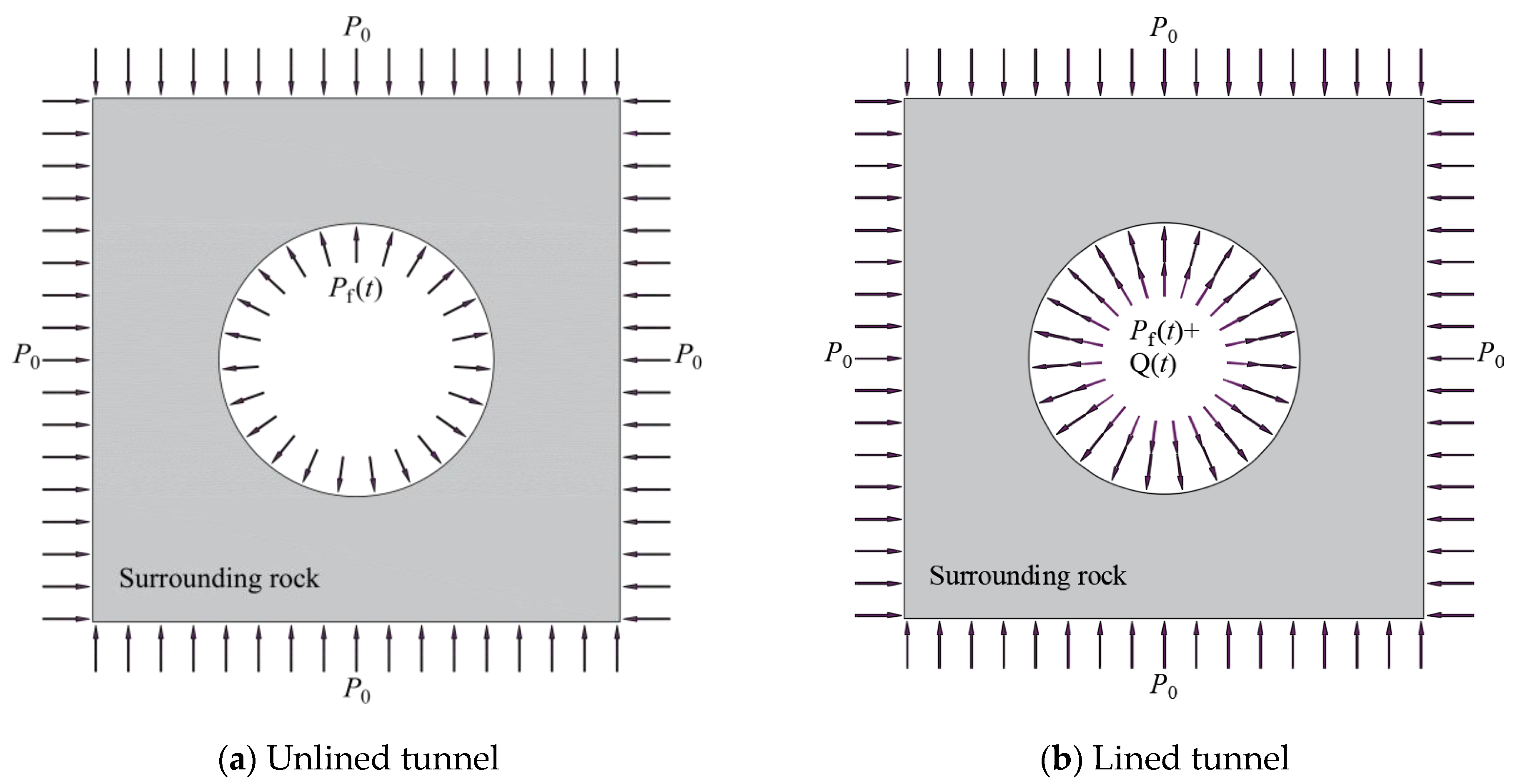
(1)
Unlined tunnel
The expression of the fictitious support pressure [36] can be expressed as follows:
p f ( t ) = 1 λ ( t ) P 0 λ ( t ) = 1 α e β t
where λ(t) is the stress release coefficient; α is the stress release rate; and β is a parameter positively related to the tunnelling rate. When α or β are equal to zero or positive infinity, then λ(t) is equal to 1, indicating that all stresses induced by the tunnel excavation are released.
This study assumes that the tunnel is excavated at time t = 0, and the lining is installed at time t = t0. Therefore, the boundary conditions of the unlined and lined tunnels (Figure 3) can be given as follows:
σ r R ( t ) r = + = P 0
σ r R ( t ) r = R 2 = P f ( t ) t t 0 P f ( t ) + Q ( t ) t > t 0
where σrR(t) is the radial stress of the surrounding rock; and Q(t) is the supporting pressure provided by the lining.
The stress distribution of the surrounding rock caused by a circular tunnel excavation under hydrostatic pressure has been studied by many researchers. Based on the boundary conditions of the unlined tunnel, the stress components of the surrounding rock can be directly given as follows:
σ r R ( t ) = 1 λ ( t ) R 2 2 r 2 P 0 σ θ R ( t ) = 1 + λ ( t ) R 2 2 r 2 P 0
where σθR(t) is the tangential stress of the surrounding rock.
Taking into account the generalized Hooke’s law, the computational formula of the longitudinal strain of the surrounding rock can be written as follows:
ε z R = σ z R v R ( σ r R + σ θ R ) E R
where σzR(t) and εzR(t) are the longitudinal stress and strain of the surrounding rock, respectively; and ER and vR are the elastic modulus and the Poisson’s ratio of the surrounding rock, respectively.
The longitudinal strain of the surrounding rock is equal to zero (εzR(t) = 0) under the state of plane strain [10]. Therefore, the longitudinal stress of the surrounding rock can be given as follows:
σ z R = v R ( σ r R + σ θ R ) = 2 v R P 0
Moreover, the mean stress of the surrounding rock can be calculated as follows:
σ m R = σ r R ( t ) + σ θ R ( t ) + σ z R ( t ) 3 = 2 ( 1 + v R ) 3 P 0
Therefore, the increments of the deviatoric stress components of the surrounding rock caused by the tunnel excavation can be calculated as follows:
Δ s r R ( t ) = 1 λ ( t ) R 2 2 r 2 P 0 σ m R ( P 0 σ m R ) = λ ( t ) R 2 2 r 2 P 0 Δ s θ R ( t ) = 1 + λ ( t ) R 2 2 r 2 P 0 σ m R ( P 0 σ m R ) = λ ( t ) R 2 2 r 2 P 0 Δ σ m R = σ m R σ m R = 2 ( 1 + v R ) P 3 2 ( 1 + v R ) P 3 = 0
where ΔsrR(t) and ΔsθR(t) are the increments of the deviatoric stresses of the surrounding rock in the radial and tangential directions, respectively; and ΔσmR is the increment of the mean stress.
The strain of the surrounding rock induced by the increments of the deviatoric stress in the tangential direction can be given as follows:
ε θ RP ( t ) = J ( t ) Δ s θ R ( 0 ) + 0 t J ( t ξ ) Δ s θ R ( ξ ) d ξ
Based on the geometric equation, the radial deformation of the surrounding rock induced by the tunnel excavation can be expressed as follows:
ε θ RP ( t ) = u r RP ( t ) r u r RP ( t ) = J ( t ) λ ( 0 ) r P 0 + r 0 t J ( t ξ ) λ ( ξ ) P 0 d ξ
Substituting r = R2 and Equation (2) (see expression J(t)) into Equation (13), the radial deformation of the surrounding rock on the tunnel wall can be calculated as follows:
u r RP ( t ) r = R 2 = R 2 P 0 2 1 G m + t η m + 1 e t / t k G k α R 2 P 0 2 1 β η m ( 1 β η m 1 G m ) e β t + e β t e t / t k G k ( 1 β t k )
(2)
Lined tunnel
The lining is assumed to be installed at time τ = tt0. The mechanical analysis of the surrounding rock under the fictitious support pressure is similar to that under the supporting pressure provided by the lining. Therefore, combining Equations (1)–(3) and Equation (12), the radial deformation of the surrounding rock can be given as follows:
u r RQ ( τ ) = r Q ( 0 ) J ( τ ) + 0 τ J ( τ ξ ) d Q ( ξ ) d ξ d ξ
The radial deformation of the surrounding rock, induced by the supporting pressure provided by the lining on the external surface of the tunnel wall, can be obtained as follows:
u r RQ ( τ ) r = R 2 = R 2 Q ( 0 ) J ( τ ) + 0 τ J ( τ ξ ) d Q ( ξ ) d ξ d ξ
According to the Riemann–Stieltjes integral [40], Equation (16) can be transformed as follows:
u r RQ ( τ ) r = R 2 = R 2 Q ( τ ) J ( 0 ) + 0 τ Q ( ξ ) d J ( τ ξ ) d ( τ ξ ) d ξ
After the lining is installed, the increment of the radial deformation of the surrounding rock on the tunnel wall, caused only by the tunnel excavation, can be obtained as follows:
R 2 h ( τ ) = u r RP ( τ + t 0 ) r = R 2 u r RP ( t 0 ) r = R 2

3.2. Mechanical Analysis of Lining

Based on the mechanical model of the lining (Figure 4), the equilibrium equation of the lining is given as follows:
d σ r L ( τ ) d r + σ r L ( τ ) σ θ L ( τ ) r = 0
where σrL(t) and σθL(t) are the radial and tangential stresses of the lining, respectively.
The constitutive equations of the lining are expressed as follows:
σ r L ( τ ) = E L ( r ) ( 1 v L ) ( 1 + v L ) ( 1 2 v L ) ε r L ( τ ) + E L ( r ) v L ( 1 + v L ) ( 1 2 v L ) ε θ L ( τ ) σ θ L ( τ ) = E L ( r ) ( 1 v L ) ( 1 + v L ) ( 1 2 v L ) ε θ L ( τ ) + E L ( r ) v L ( 1 + v L ) ( 1 2 v L ) ε r L ( τ )
where EL(r) and vL are the elastic modulus and the Poisson’s ratio of the lining, respectively; and εrL(t) and εθL(t) are the radial and tangential strains of the lining, respectively.
The geometric equations of the lining are given as follows:
ε r L ( τ ) = d u r L ( τ ) d r ε θ L ( τ ) = u r L ( τ ) r
where urL(τ) is the radial deformation of the lining.
As mentioned above, the elastic modulus of the lining is a function of the radial coordinate. In this study, this function is assumed to be a power function defined as follows:
E L ( r ) = E 0 L r δ
where EL0 is the initial value of the elastic modulus of the lining; and δ is the radially inhomogeneous coefficient of the lining. When δ is equal to zero, the inhomogeneous degree of the lining is equal to zero, indicating that the lining is a homogeneous material.
Substituting Equations (20)–(22) into Equation (19), the governing equation in terms of radial deformation of the lining can be obtained as follows:
d 2 u r L ( τ ) d r 2 + δ + 1 r d u r L ( τ ) d r + ( δ + 1 ) v L 1 ( 1 v L ) r 2 u r L ( τ ) = 0
The boundary conditions of the lining are set as follows:
σ r L ( τ ) r = R 1 = q ( τ ) σ r L ( τ ) r = R 2 = Q ( τ )
Based on the boundary conditions, the solution of the governing equation Equation (23) can be obtained as follows:
u r L ( τ ) = R 2 A 0 E ( r ) q ( τ ) + A 0 F ( r ) Q ( τ )
in which
A 0 = 1 R 2 1 W ( R 1 ) M ( R 2 ) W ( R 2 ) M ( R 1 ) E ( r ) = M ( R 2 ) r a 1 W ( R 2 ) r a 2 F ( r ) = W ( R 1 ) r a 2 M ( R 1 ) r a 1 W ( r ) = r δ + a 1 1 a 1 E 0 L ( 1 v L ) ( 1 + v L ) ( 1 2 v L ) + E 0 L v L ( 1 + v L ) ( 1 2 v L ) M ( r ) = r δ + a 2 1 a 2 E 0 L ( 1 v L ) ( 1 + v L ) ( 1 2 v L ) + E 0 L v L ( 1 + v L ) ( 1 2 v L ) a 1 = δ ( δ ) 2 4 δ ϑ + 4 2 a 2 = δ + ( δ ) 2 4 δ ϑ + 4 2 ϑ = v L 1 v L

3.3. Deformation Compatibility on Rock–Lining Interface

As there is no slip at the rock–lining interface (tt0), the equation of the deformation compatibility on the rock–lining interface can be written as follows:
u r RP ( τ + t 0 ) r = R 2 u r RP ( t 0 ) r = R 2 u r RQ ( τ ) r = R 2 = u r L ( τ ) r = R 2
Substituting Equations (17)–(18) and Equation (25) into Equation (27), Equation (27) can be rewritten as follows:
h ( τ ) Q ( τ ) J ( 0 ) + 0 τ Q ( ξ ) d J ( τ ξ ) d ( τ ξ ) d ξ = A 0 E ( R 2 ) Q ( τ ) + A 0 F ( R 2 ) q ( τ )
Based on the Laplace transform method [41], the expression of the supporting pressure, provided by the lining about parameter of time τ, can be obtained as follows:
Q ( s ) = h ( s ) A 0 E ( R 2 ) q ( s ) s J ( s ) + A 0 F ( R 2 )
where Q(s), h(s), q(s), and J(s) are the expressions of the Laplace transform of Q(τ), h(τ), q(τ), and J(τ), respectively.
The expressions of the h(s) and the J(s) can be given as follows:
h ( s ) = 1 2 η m s 2 + b 1 2 ( 1 s 1 s + β ) + b 2 2 ( 1 s 1 s + 1 / t k ) P 0 J ( s ) = 1 2 s 1 G m + 1 η m s + 1 η k ( s + 1 / t k )
in which
b 1 = α ( 1 G k ( 1 β t k ) + 1 G m 1 β η m ) e β t 0 b 2 = ( 1 G k 1 G k ( 1 β t k ) ) e t 0 / t k
Substituting Equation (30) into Equation (29), Equation (29) can be rewritten as follows:
Q ( s ) = 1 η m ( s + β ) ( s + 1 t k ) P 0 + b 1 β s ( s + 1 t k ) P 0 + b 2 s ( s + m ) 1 t k P 2 A 0 E ( R 2 ) q ( s ) s 2 ( s + β ) ( s + 1 / t k ) s 2 ( s + β ) ( s + 1 / t k ) 1 G m + 1 η m s + 1 η k ( s + 1 / t k ) + 2 A 0 F ( R 2 )
Equation (32) can be further simplified as follows:
Q ( s ) = 1 η m ( s + β ) ( s + 1 t k ) P 0 + b 1 β s ( s + 1 t k ) P 0 + b 2 s ( s + m ) 1 t k P 0 s ( s + β ) a 11 ( s x 1 ) ( s x 2 ) f ( s )
in which
a 11 = 1 G m + 2 A 0 F ( R 2 ) b 11 = ( 1 G m + 1 G k + 2 A 0 F ( R 2 ) ) 1 t k + 1 η m c 11 = 1 η m t k Δ = ( b 11 a 11 ) 2 4 c 11 a 11 x 1 , 2 = b 11 / a 11 ± Δ 2 f ( s ) = 2 A 0 E ( R 2 ) q ( s ) s ( s + 1 / t k ) a 11 ( s x 1 ) ( s x 2 )
Using the Laplace transform inversion [42,43,44] about parameter s in Equation (33), the expression of the Q(τ) can be given as follows:
Q ( τ ) = P 0 a 11 η m e x 1 τ e x 2 τ x 1 x 2 + 1 t k x 1 x 2 ( 1 + x 2 e x 1 τ x 1 e x 2 τ x 1 x 2 ) + P 0 b 1 β a 11 ( x 1 + 1 / t k ) e x 1 τ ( x 1 + β ) ( x 1 x 2 ) ( x 2 + 1 / t k ) e x 2 τ ( x 2 + β ) ( x 1 x 2 ) + e β τ ( 1 / t k β ) ( x 1 + β ) ( x 2 + β ) + P 0 b 2 ( e x 1 τ e x 2 τ ) a 11 t k ( x 1 x 2 ) Q 4 ( τ )
where Q4(τ) is the expression of Laplace transform inversion of f(s) (see Equation(34)).
When the inner surface pressure of the lining q(τ) in the radial direction is defined, q(s) can be deduced by the Laplace transform about parameter τ. Then, Q4(τ) can be deduced by the Laplace transform inversion about parameter s of the f(s).
Subsequently, the corresponding solutions of Q4(τ) are derived as follows:
(a) When the inner surface pressure acting on the lining along the radial direction is constant, the expression of q(τ) can be given by:
q ( τ ) = W
where W is the water pressure.
Using Laplace transform, the expression of the q(s) can be given by:
q ( s ) = W s
Substituting Equation (37) into Equation (34) (see expression f(s)), f(s) can be obtained as follows:
f ( s ) = 2 W A 0 E ( R 2 ) ( s + 1 / t k ) a 11 ( s x 1 ) ( s x 2 )
Using the Laplace transform inversion, the expression of Q4(τ) can be derived as follows:
Q ( τ ) 4 = 2 A 0 E ( R 2 ) W e τ x 1 ( 1 + t k x 1 ) e τ x 2 ( 1 + t k x 2 ) a 11 t k ( x 1 x 2 )
(b) When the inner surface pressure acting on the lining along the radial direction changes, the expression of q(τ) can be given as follows:
q ( τ ) = F 0 e ζ τ sin ( χ τ + ψ )
where F0 is the initial amplitude of the aerodynamic pressure; ζ is the damping coefficient of the aerodynamic pressure; χ is the angular frequency of the aerodynamic pressure; and ψ is the initial phase angle of the aerodynamic pressure.
Using Laplace transform, the expression of q(s) can be given as follows:
q ( s ) = F 0 sin ( ψ ) ( ς + s ) + χ cos ( ψ ) ( ς + s ) 2 + χ 2
Substituting Equation (41) into Equation (34) (see expression f(s)), f(s) can be obtained as follows:
f ( s ) = 2 F 0 A 0 E ( R 2 ) s ( s + 1 / t k ) a 11 ( s x 1 ) ( s x 2 ) sin ( ψ ) ( ς + s ) 2 + χ cos ( ψ ) ( ς + s ) 2 + χ 2
Using the Laplace transform inversion, Q4(τ) can be expressed as follows:
Q ( τ ) 4 = 2 A 0 E ( R 2 ) F 0 a 11 t d ( x 1 x 2 ) x 1 e τ x 1 ( χ + χ t d x 1 ) cos ( ψ ) + H 10 sin ( ψ ) H 8 x 2 e τ x 2 ( χ + χ t d x 2 ) cos ( ψ ) + H 11 sin ( ψ ) H 9 e ζ t L 1 cosh ( χ t 1 i ) + sinh ( χ t 1 i ) ( ζ L 2 ) 1 i χ a 11 t d H 8 H 9
in which
H 1 = ζ 4 + ζ 3 x 1 + ζ 3 x 2 + ζ χ 2 x 1 + ζ χ 2 x 2 + ζ 2 x 1 x 2 + χ 2 x 1 x 2 H 2 = 2 ζ 3 χ 2 t d + χ 4 + ζ 5 t d + ζ χ 4 t d + ζ 4 t d x 1 + ζ 4 t d x 2 + χ 4 t d x 1 + χ 4 t d x 2 + ζ 3 t d x 1 x 2 + 2 ζ 2 χ 2 t d x 1 + 2 ζ 2 χ 2 t d x 2 + ζ χ 2 t d x 1 x 2 H 3 = 2 ζ χ 3 + 2 ζ 3 χ + χ 3 x 1 + χ 3 x 2 + ζ 2 χ x 1 + ζ 2 χ x 2 + χ 3 t d x 1 x 2 + ζ 2 χ t d x 1 x 2 H 4 = χ 5 t d + ζ 4 χ t d + 2 ζ 2 χ 3 t d H 5 = χ 3 + ζ 2 χ t d x 1 + ζ 2 χ t d x 2 + χ 3 t d x 1 + χ 3 t d x 2 + ζ 2 χ + 2 ζ χ t d x 1 x 2 χ x 1 x 2 H 6 = ζ 3 + ζ χ 2 + ζ 2 x 1 + ζ 2 x 2 + χ 2 x 1 + χ 2 x 2 + ζ x 1 x 2 + χ 2 t d x 1 x 2 H 7 = ζ 4 t d χ 4 t d 2 ζ 2 χ 2 t d ζ 3 t d x 1 ζ 3 t d x 2 ζ χ 2 t d x 1 ζ χ 2 t d x 2 ζ 2 t d x 1 x 2 H 8 = ζ 2 + 2 ζ x 1 + χ 2 + x 1 2 H 9 = ζ 2 + 2 ζ x 2 + χ 2 + x 2 2 H 10 = ζ + x 1 + t d x 1 2 + ζ t d x 1 H 11 = ς + x 2 + t d x 2 2 + ς t d x 2 L 1 = 2 A 0 E ( R 2 ) F 0 H 5 cos ( ψ ) + ( H 6 H 7 ) sin ( ψ ) L 2 = ( H 1 H 2 ) sin ( ψ ) + ( H 3 H 4 ) cos ( ψ ) H 5 cos ( ψ ) + ( H 6 H 7 ) sin ( ψ )

4. Validation

4.1. Comparison with Existing Analytical Solution

The analytical solution of a circular lined tunnel was deduced considering both the tunnel face effect and the rheological behavior of the rock mass with different rheological models under hydrostatic pressure [10]. For the Burgers model, the expressions of the radial deformation on the rock–lining interface ui(τ) (corresponding to Equation (24) in the reference) and supporting pressure provided by the lining Q(τ) (corresponding to Equations (35)–(38) in the reference) are given as follows (note that the notations of the reference are modified to the ones of the present paper):
u i ( τ ) = u r L ( τ ) r = R 2 = Q ( τ ) K s R 2
Q ( τ ) = P 0 a 11 η m e x 1 τ e x 2 τ x 1 x 2 + 1 t k x 1 x 2 ( 1 + x 2 e x 1 τ x 1 e x 2 τ x 1 x 2 ) + P 0 b 1 β a 11 ( x 1 + 1 / t k ) e x 1 τ ( x 1 + β ) ( x 1 x 2 ) ( x 2 + 1 / t k ) e x 2 τ ( x 2 + β ) ( x 1 x 2 ) + e β τ ( 1 / t k β ) ( x 1 + β ) ( x 2 + β ) + P 0 b 2 ( e x 1 τ e x 2 τ ) a 11 t k ( x 1 x 2 )
in which
b 1 = α ( 1 G k ( 1 β t k ) + 1 G m 1 β η m ) e β t 0 b 2 = ( 1 G k 1 G k ( 1 β t k ) ) e t 0 t k a 11 = 1 G m + 2 K s b 11 = ( 1 G m + 1 G k + 2 K s ) 1 t k + 1 η m c 11 = 1 η m t k Δ = ( b 11 a 11 ) 2 4 c 11 a 11 x 1 , 2 = b 11 / a 11 ± Δ 2 K s = ( 1 R 1 2 / R 2 2 ) E 0 L ( 1 2 v L + R 1 2 / R 2 2 ) ( 1 + v L )
When the inhomogeneous coefficient of the lining (δ) is equal to zero, the subitem A0F(R2) can be expressed as follows:
A 0 F ( R 2 ) Q ( τ ) = ( 1 2 v L + R 1 2 / R 2 2 ) ( 1 + v L ) ( 1 R 1 2 / R 2 2 ) E 0 L Q ( τ ) = Q ( τ ) K s
When the radial inner surface radial pressure of the lining (q(τ)) is also equal to zero, the subitems A0E(R2)q(τ) and Q4(τ) can be given as follows:
A 0 E ( R 2 ) q ( τ ) = 0 Q ( τ ) 4 = 0
In this case, Equations (25) and (35) are the same as Equations (45) and (46), respectively.

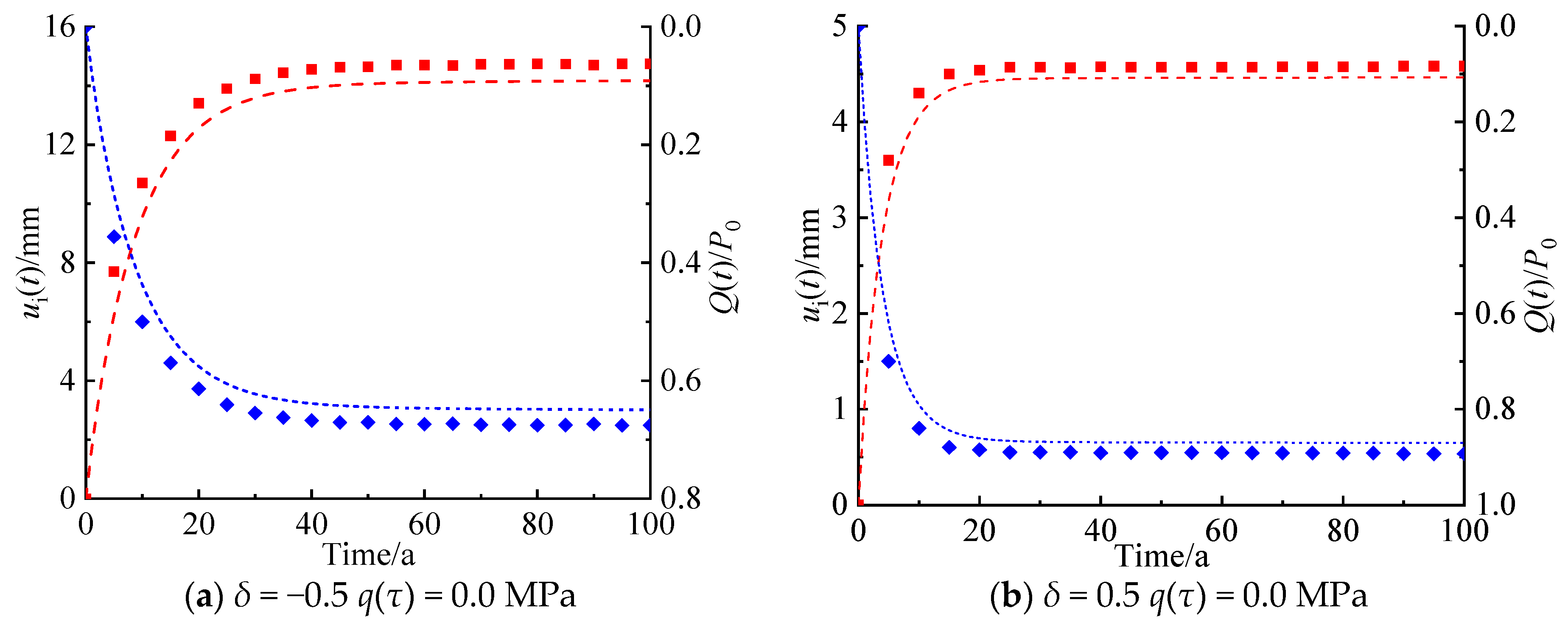
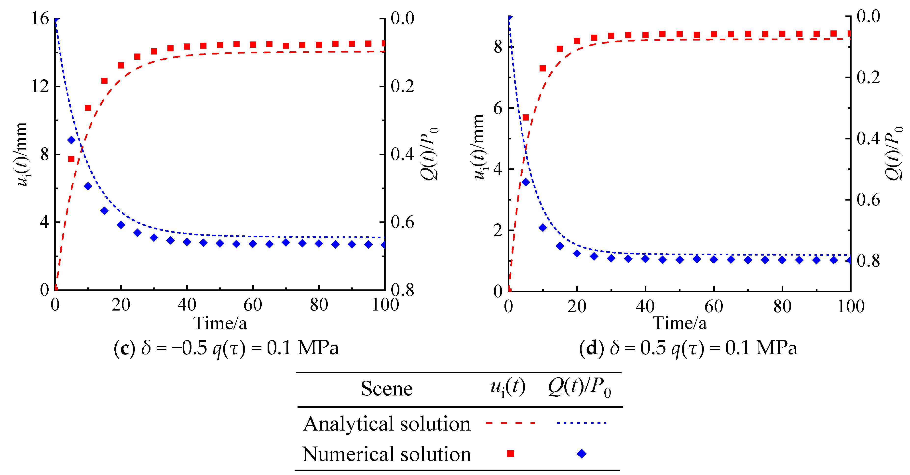
4.2. Comparison with Numerical Simulation

To further validate our proposed analytical model, the results of this analytical model are compared with those of a numerical simulation using the FLAC3D5.01 finite differences code. The parameters used for this verification are taken from the literature [10,36] and are shown in Table 1. A three-dimensional numerical simulation with plane strain condition is carried out. A quarter of the numerical model used for this verification is shown in Figure 5. The left and lower sides of the model are set as axisymmetric boundary conditions, the upper side is set as a free boundary, and other positions are set as displacement-constrained boundary conditions. The thickness, width, and height of the numerical model are set as 1.0 m, 80 m, and 80 m, respectively. The lining is simulated with the solid elements, and its elastic modulus is divided into 20 layers, equally spaced along the radial direction.
Four combinations of two different values for the radially inhomogeneous coefficients (δ) and the inner surface pressures of the lining in the radial direction (q(τ)) are assumed. For these values, the radial deformation on the rock–lining interface ui(τ), and the normalized supporting pressure provided by the lining denoted as Q(τ)/P0, are obtained by the proposed theoretical model and the three-dimensional simulation. The time-history curves of ui(τ) and Q(τ)/P0 obtained by the two methods are shown in Figure 6, showing good consistency. The maximum difference for all cases is smaller than 10%.

5. Parametric Analysis

Based on the proposed mechanical model, the main factors influencing the radial deformation on the rock–lining interface (ui(τ)) and the normalized supporting pressure provided by the lining (Q(τ)/P0) are further explored in the following section. Such factors are the radially inhomogeneous coefficient, inner surface pressure, and thickness of the lining, the relaxation time of the Maxwell model, and the retardation time of the Kelvin model. The control parameters of the proposed mechanical model used in the subsequent analysis are also shown in Table 1.

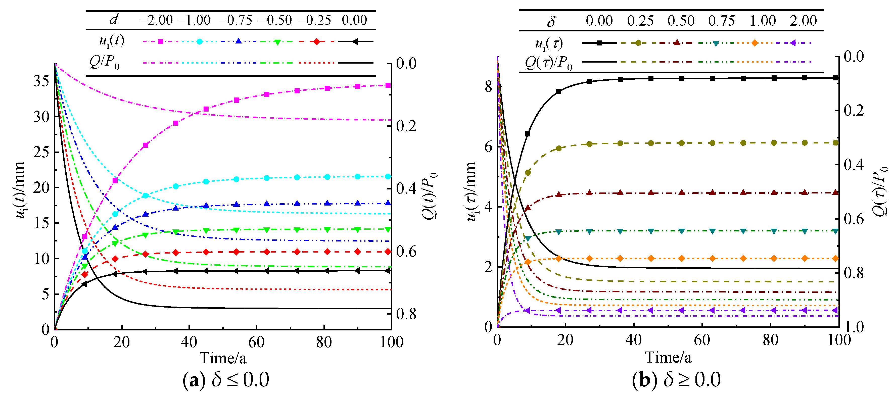
5.1. Radially Inhomogeneous Coefficient of Lining

The time-history curves of the radial deformation on the rock–lining interface (ui(τ)) and the normalized supporting pressure provided by the lining (Q(τ)/P0) with respect to the radially inhomogeneous coefficient of the lining (δ) are shown in Figure 7. When δ increases from −2.0 to 2.0, ui(τ) decreases, and Q(τ)/P0 increases. When δ increases from −2.0 to 0.0, us(τ) decreases from 31.84 mm to 8.27 mm, and Q(τ)/P0 increases from 0.17 to 0.78 at τ =50 a. When δ increases from 0.0 to 2.0, ui(τ) decreases from 8.27 mm to 0.56 mm, and Q(τ)/P0 increases from 0.78 to 0.96 at τ =50 a. It can be noted that the influence of the change of the negative number δ on ui(τ) and Q(τ)/P0 is significantly larger than that of the positive number δ. In addition, when the absolute value of the positive number δ is equal to that of the negative number δ, the times required for an apparent stabilization of ui(τ) and Q(τ)/P0 for the negative number δ are longer than that for the positive number δ.

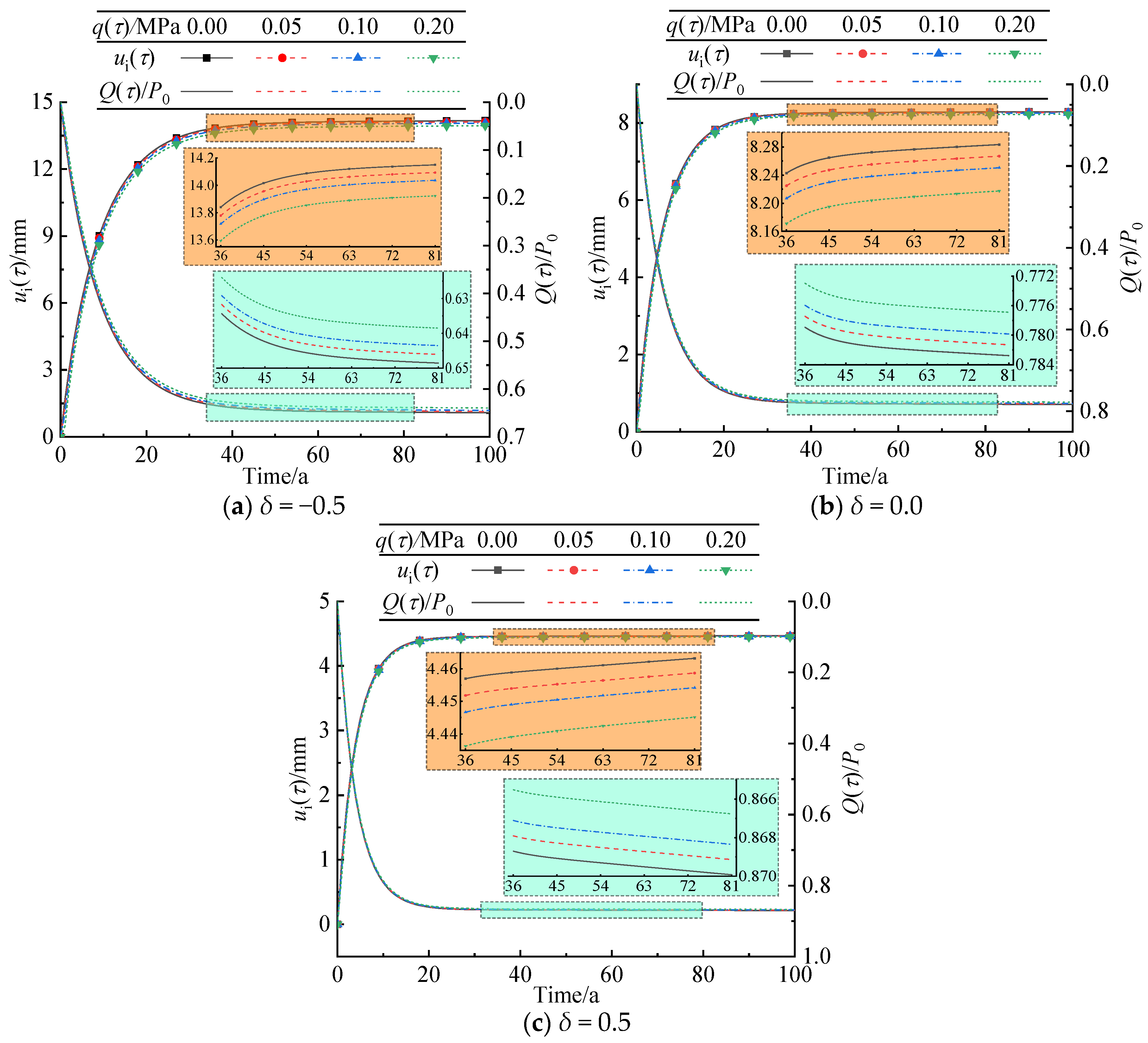
5.2. Radially Inner Surface Pressure of Lining

The time-history curves of the radial deformation on the rock–lining interface (ui(τ)) and the normalized supporting pressure provided by the lining (Q(τ)/P0) for a range of radially inner surface pressures of the lining (q(τ)) are shown in Figure 8. When q(τ) increases from 0.00 MPa to 0.20 MPa, both ui(τ) and Q(τ)/P0 decrease, but the times required for an apparent stabilization of ui(τ) and Q(τ)/P0 are the same for every value of q(τ). The influences of the change in q(τ) on ui(τ) and Q(τ)/P0 is negligible.

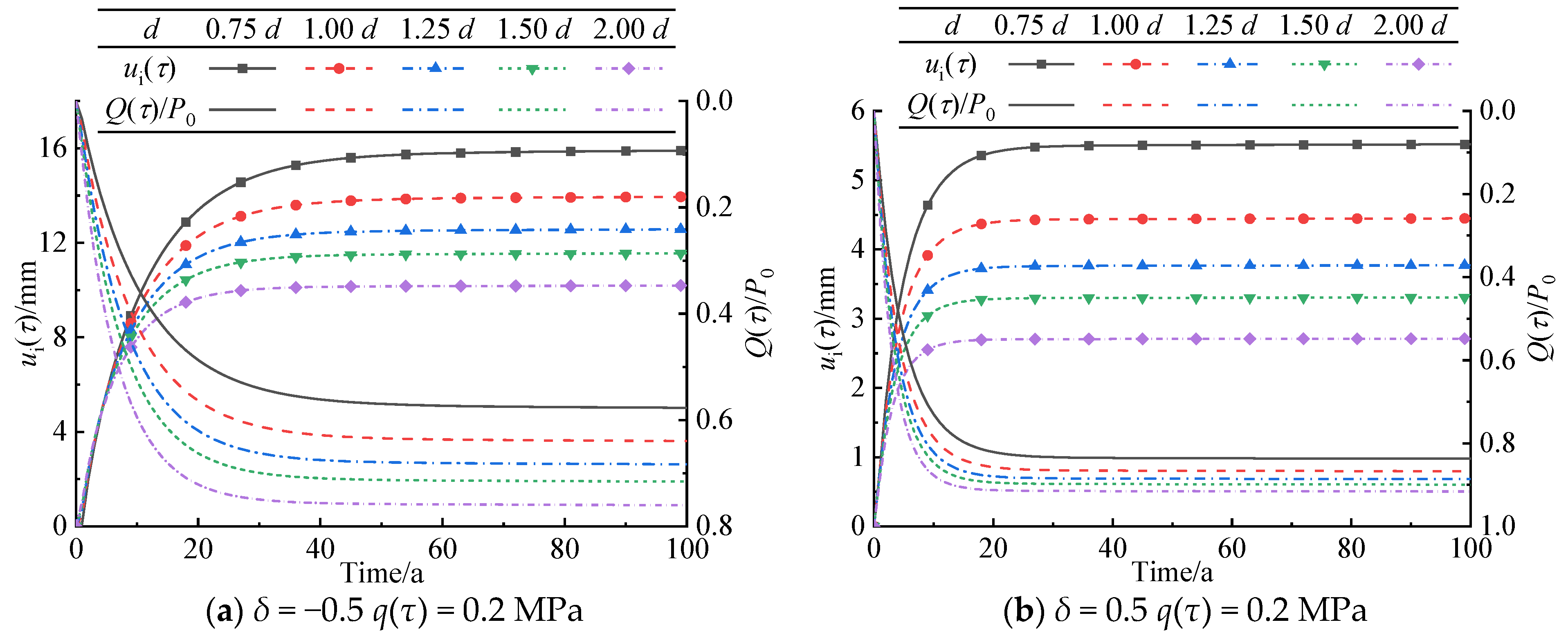
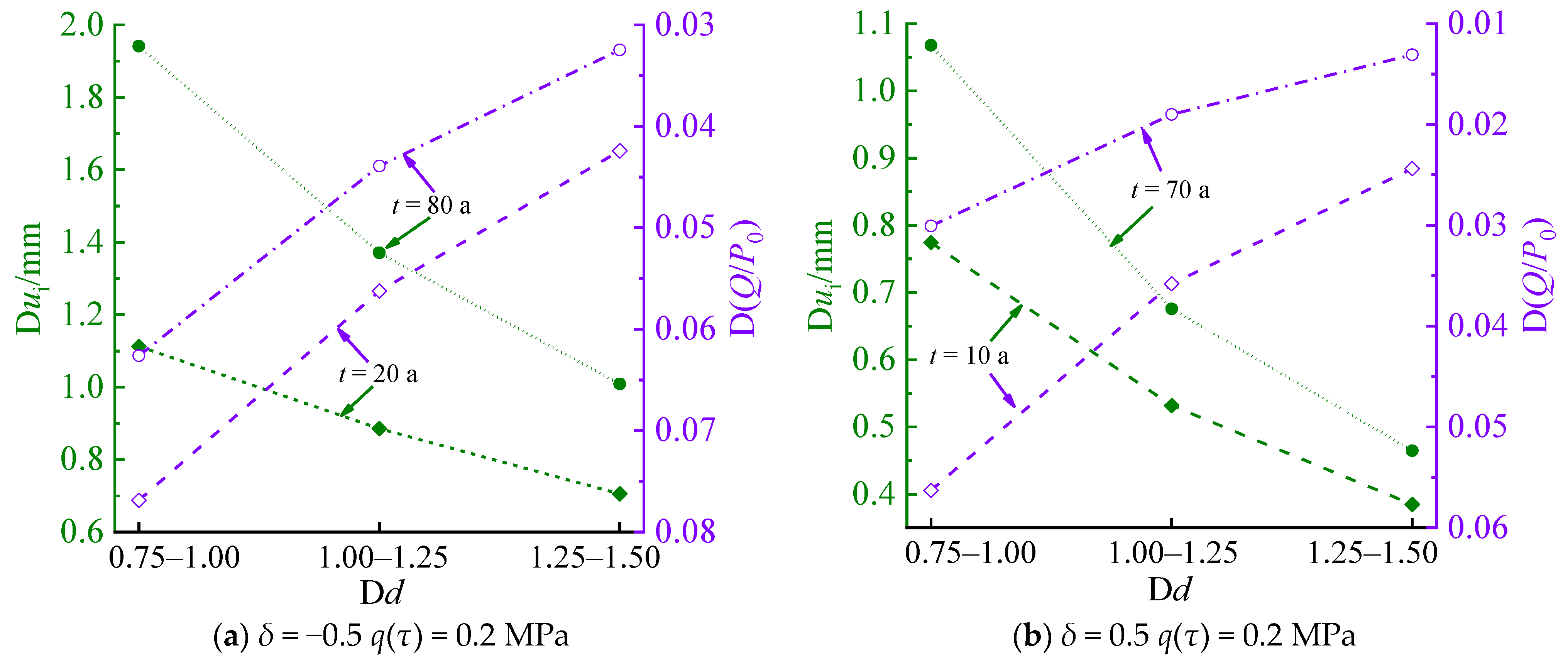
5.3. Lining Thickness

The time-history curves of the radial deformation on the rock–lining interface (ui(τ)) and the normalized supporting pressure provided by the lining (Q(τ)/P0) with respect to the lining thickness (d) are shown in Figure 9. When d increases from 0.75 d to 2.00 d, ui(τ) decreases, and Q(τ)/P0 increases. The time required for an apparent stabilization of ui(τ) and Q(τ)/P0 decreases.
The relationships between Δui(τ), ΔQ(τ)/P0, and Δd are shown in Figure 10. When d increases by a specific increment, Δui(τ) and ΔQ(τ)/P0 decrease, indicating that the influence of d on ui(τ) and Q(τ)/P0 weakens.

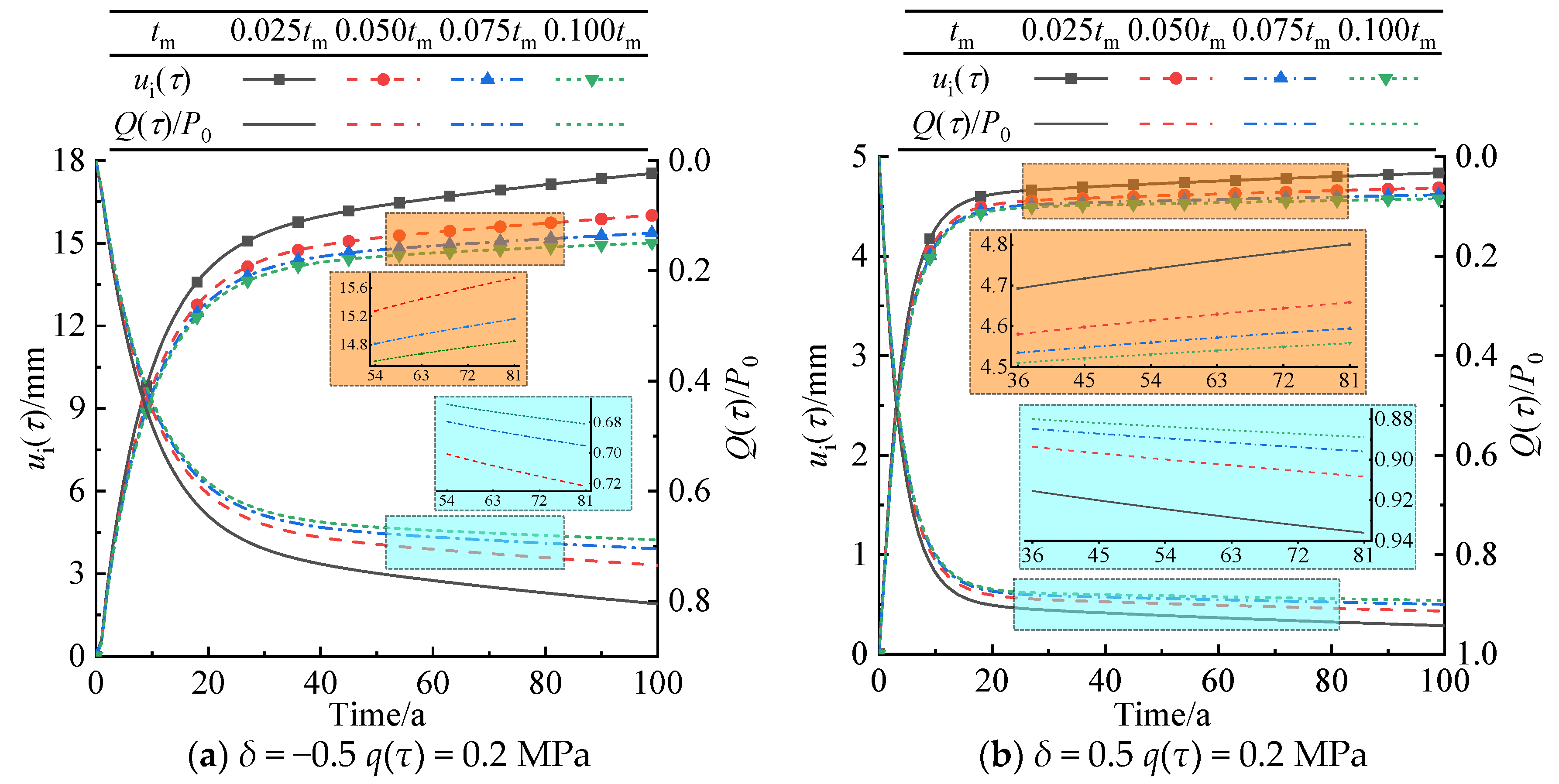
5.4. Relaxation Time of Maxwell Model

The time-history curves of the radial deformation on the rock–lining interface (ui(τ)) and the normalized supporting pressure provided by the lining (Q(τ)/P0) with respect to the relaxation time of the Maxwell model (tm) are shown in Figure 11. When tm increases from 0.025 tm to 0.100 tm, both ui(τ) and Q(τ)/P0 decrease.

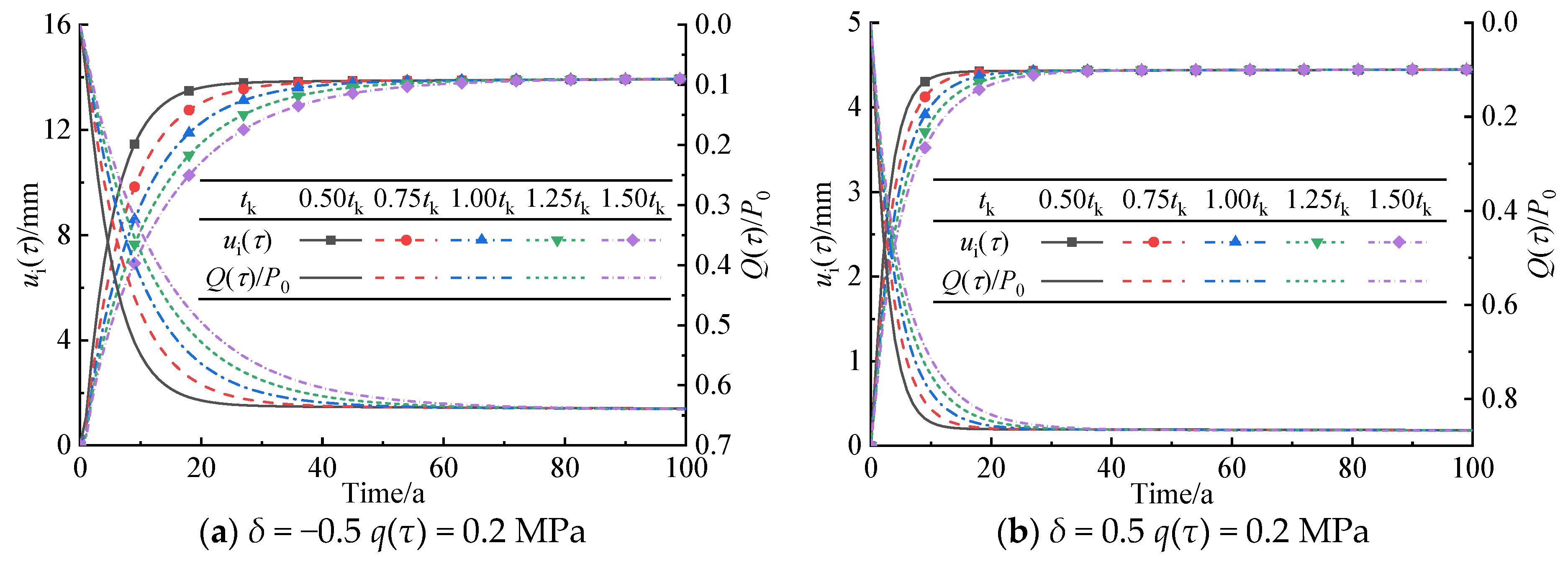
5.5. Retardation Time of Kelvin Model

The time-history curves of the radial deformation on the rock–lining interface (ui(τ)) and the normalized supporting pressure provided by the lining (Q(τ)/P0) for different retardation times of the Kelvin model (tk) are shown in Figure 12. When tk increases from 0.50 tk to 1.50 tk, the time required for an apparent stabilization of ui(τ) and Q(τ)/P0 increases, but the ultimate stable values of ui(τ) and Q(τ)/P0 are constant.

6. Conclusions

This study explores the influence of the mechanical property of the lining subjected to inner surface pressure along the radial direction, and the rheological behavior of the rock mass on the mechanical response of the rock–lining interface under hydrostatic pressure. The main conclusions are summarized as follows:
(1) When both the inhomogeneous coefficient (δ) and the inner surface pressure (q(τ)) of the lining in the radial direction are equal to zero, the proposed analytical solution is the same as the existing analytical solution.
(2) The influences of the change of the negative value of the radially inhomogeneous coefficient of the lining (δ) on the radial deformation on the rock–lining interface (ui(τ)) and the normalized supporting pressure provided by the lining (Q(τ)/P0) are significantly larger than that of the positive value. These parameters decrease with the increase of the radially inner surface pressures of the lining (q(τ)).
(3) The radial deformation on the rock–lining interface (ui(τ)) and the normalized supporting pressure provided by the lining (Q(τ)/P0) decrease with the increase of the relaxation time of the Maxwell model. The time required for an apparent stabilization of their values increases with the increase of the retardation time of the Kelvin model, but their ultimate stable values are constant.
(4) The functional gradient lining can be applied to the structural design of tunnel engineering in further work.

Author Contributions

Methodology, J.D.; Software, J.D.; Validation, J.D.; Resources, X.Z.; Data curation, X.Z.; Writing—original draft, J.D.; Supervision, X.Z. All authors have read and agreed to the published version of the manuscript.

Funding

This research was funded by the Key Project of CCCC Highway Engineering Co., Ltd., China under Grant KJYF-2021-B-20.

Institutional Review Board Statement

Not applicable.

Informed Consent Statement

Not applicable.

Data Availability Statement

The data used to support the findings of this study are available from the corresponding author upon request.

Acknowledgments

We thank the anonymous reviewers and editors for their constructive comments and suggestions to improve the quality of this article.

Conflicts of Interest

The authors declare that this study received funding from the Key Project of CCCC Highway Engineering Co., Ltd., China. The funder had the following involvement with the study: Analytical Model of Mechanical Responses of Circular Tunnels Considering Rheological Behavior of Surrounding Rock and Functionally Graded Lining.

References

  1. Fang, Q.; Zhang, D.L.; Li, Q.Q.; Wong, L.N.Y. Effects of twin tunnels construction beneath existing shield-driven twin tunnels. Tunn. Undergr. Space Technol. 2014, 45, 128–137. [Google Scholar] [CrossRef]
  2. Revesz, A.; Chaer, I.; Thompson, J.; Mavroulidou, M.; Gunn, M.; Maidment, G. Ground source heat pumps and their interactions with underground railway tunnels in an urban environment: A review. Appl. Therm. Eng. 2016, 93, 147–154. [Google Scholar] [CrossRef]
  3. Mu, W.Q.; Li, L.C.; Chen, D.Z.; Wang, S.X.; Xiao, F.K. Long-term deformation and control structure of rheological tunnels based on numerical simulation and on-site monitoring. Eng. Fail. Anal. 2020, 118, 104928. [Google Scholar] [CrossRef]
  4. Du, J.M.; Fang, Q.; Wang, J.; Wang, G. Influences of high-speed train speed on tunnel aerodynamic pressures. Appl. Sci. 2022, 12, 303. [Google Scholar] [CrossRef]
  5. Du, J.M.; Fang, Q.; Zhang, X.; Wang, H.L. Aerodynamic effect associated with tunnel length. KSCE J. Civ. Eng. 2024, 28, 2997–3008. [Google Scholar] [CrossRef]
  6. Liu, S.H.; Shi, Y.; Sun, R.; Yang, J.S. Damage behavior and maintenance design of tunnel lining based on numerical evaluation. Eng. Fail. Anal. 2020, 109, 104209. [Google Scholar] [CrossRef]
  7. Namli, M. Evaluation of the effect of using fiber reinforcement in tunnel linings for metro projects. Undergr. Space 2021, 6, 732–750. [Google Scholar] [CrossRef]
  8. Du, J.M.; Zhang, X.; Wang, H.L. Elasto-plastic solution for a circular lined tunnel considering yield criteria for surrounding rock and functionally graded lining in cold-region tunnels. Sustainability 2023, 15, 11577. [Google Scholar] [CrossRef]
  9. Wang, H.N.; Utili, S.; Jiang, M.J. An analytical approach for the sequential excavation of axisymmetric lined tunnels in viscoelastic rock. Int. J. Rock Mech. Min. Sci. 2014, 68, 85–106. [Google Scholar] [CrossRef]
  10. Chu, Z.F.; Wu, Z.J.; Liu, B.G.; Liu, Q.S. Coupled analytical solutions for deep-buried circular lined tunnels considering tunnel face advancement and soft rock rheology effects. Tunn. Undergr. Space Technol. 2019, 94, 103111. [Google Scholar] [CrossRef]
  11. Du, J.M.; Fang, Q.; Wang, G.; Wang, J. Analytical solution of a circular lined tunnel with alterable mechanical property under hydrostatic stress and internal pressure. J. Central South Univ. 2022, 29, 2757–2770. [Google Scholar] [CrossRef]
  12. Zhang, Y.; Shao, J.F.; Xu, W.Y.; Jia, Y.; Zhao, H.B. Creep behaviour and permeability evolution of cataclastic sandstone in triaxial rheological tests. Eur. J. Environ. Civ. Eng. 2015, 19, 496–519. [Google Scholar] [CrossRef]
  13. Chen, Z.Q.; He, C.; Wang, J.; Ma, C.C. Time-dependent squeezing deformation mechanism of tunnels in layered soft-rock stratum under high geo-stress. J. Mt. Sci. 2021, 18, 1371–1390. [Google Scholar] [CrossRef]
  14. Zaheri, M.; Ranjbarnia, M.; Oreste, P. Reliability analysis of deep pressurized tunnels excavated in the rock mass with rheological behavior. Transp. Geotech. 2024, 45, 101212. [Google Scholar] [CrossRef]
  15. Guan, Z.C.; Jiang, Y.J.; Tanabashi, Y. Rheological parameter estimation for the prediction of long-term deformations in conventional tunnelling. Tunn. Undergr. Space Technol. 2009, 24, 250–259. [Google Scholar] [CrossRef]
  16. Bonini, M.; Barla, G. The Saint Martin La Porte access adit (Lyon–Turin Base Tunnel) revisited. Tunn. Undergr. Space Technol. 2012, 30, 38–54. [Google Scholar] [CrossRef]
  17. Sharifzadeh, M.; Daraei, R.; Broojerdi, M.S. Design of sequential excavation tunneling in weak rocks through findings obtained from displacements based back analysis. Tunn. Undergr. Space Technol. 2012, 28, 10–17. [Google Scholar] [CrossRef]
  18. Wang, F.N.; Guo, Z.B.; Qiao, X.B.; Fan, J.Y.; Li, W.; Mi, M.; Tao, Z.G.; He, M.C. Large deformation mechanism of thin-layered carbonaceous slate and energy coupling support technology of NPR anchor cable in Minxian Tunnel: A case study. Tunn. Undergr. Space Technol. 2021, 117, 104151. [Google Scholar] [CrossRef]
  19. Tao, Z.G.; Ren, S.L.; Li, G.; Xu, H.T.; Luo, S.L.; He, M.C. Model test on support scheme for carbonaceous slate tunnel in high geostress zone at high depth. J. Mt. Sci. 2021, 18, 764–778. [Google Scholar] [CrossRef]
  20. Wang, G.; Fang, F.; Han, W.; Jiang, Y.J.; Zhang, X.D.; Xu, F.; Zhang, S.B. Coupled rheological behavior of tunnel rock masses reinforced by rock bolts based on the non-hydrostatic stress field. Tunn. Undergr. Space Technol. 2023, 137, 105112. [Google Scholar] [CrossRef]
  21. Wan, Z.; Li, S.C.; Zhao, S.S.; Liu, R.C. Rheological characterization of the conditioned sandy soil under gas-loading pressure for earth pressure balance shield tunnelling. Tunn. Undergr. Space Technol. 2024, 146, 105658. [Google Scholar] [CrossRef]
  22. Arora, K.; Gutierrez, M.; Hedayat, A. Physical model simulation of rock-support interaction for the tunnel in squeezing ground. J. Rock Mech. Geotech. Eng. 2022, 14, 82–92. [Google Scholar] [CrossRef]
  23. Guo, Y.D.; Li, X.G.; Fang, Y.F.; Jin, D.L.; Yang, Y.; Liu, H.Z. Investigation into the pregelatinized starch additive alleviated the deterioration in rheological properties of slurries induced by high-temperature environment and seawater intrusion during submarine slurry shield tunneling. Tunn. Undergr. Space Technol. 2024, 147, 105693. [Google Scholar] [CrossRef]
  24. Xu, G.W.; Gutierrez, M. Study on the damage evolution in secondary tunnel lining under the combined actions of corrosion degradation of preliminary support and creep deformation of surrounding rock. Transp. Geotech. 2021, 27, 100501. [Google Scholar] [CrossRef]
  25. Zeng, G.S.; Wang, H.N.; Song, F.; Rodriguez-Dono, A. Time-dependent analytical solutions for tunnels excavated in anisotropic rheological rock masses. Tunn. Undergr. Space Technol. 2024, 152, 105890. [Google Scholar] [CrossRef]
  26. Zhang, Z.G.; Huang, M.H.; Pan, Y.T.; Jiang, K.M.; Li, Z.N.; Ma, S.K.; Zhang, Y.N. Analytical prediction of time-dependent behavior for tunneling-induced ground movements and stresses subjected to surcharge loading based on rheological mechanics. Comput. Geotech. 2021, 129, 103858. [Google Scholar] [CrossRef]
  27. Liu, C.; Zhang, D.L.; Zhang, S.L.; Fang, Q.; Sun, Z.Y. Long-term mechanical analysis of tunnel structures in rheological rock considering the degradation of primary lining. Undergr. Space 2023, 10, 217–232. [Google Scholar] [CrossRef]
  28. Carranza-Torres, C.; Rysdahl, B.; Kasim, M. On the elastic analysis of a circular lined tunnel considering the delayed installation of the support. Tunn. Undergr. Space Technol. 2013, 61, 57–85. [Google Scholar] [CrossRef]
  29. Du, J.M.; Fang, Q.; Wang, G.; Zhang, D.L.; Chen, T.L. Fatigue damage and residual life of secondary lining of high-speed railway tunnel under aerodynamic pressure wave. Tunn. Undergr. Space Technol. 2021, 111, 103851. [Google Scholar] [CrossRef]
  30. Sun, Z.Y.; Zhang, D.L.; Fang, Q.; Wang, J.C.; Chu, Z.F.; Hou, Y.J. Analysis of interaction between tunnel support system and surrounding rock for underwater mined tunnels considering the combined effect of blasting damage and seepage pressure. Tunn. Undergr. Space Technol. 2023, 141, 105314. [Google Scholar] [CrossRef]
  31. Zhao, D.P.; Jia, L.L.; Wang, M.N.; Wang, F. Displacement prediction of tunnels based on a generalised Kelvin constitutive model and its application in a subsea tunnel. Tunn. Undergr. Space Technol. 2016, 54, 29–36. [Google Scholar] [CrossRef]
  32. Cui, L.; Sheng, Q.; Dong, Y.K.; Miao, C.X.; Huang, J.H.; Zhang, A.J. Two-stage analysis of interaction between strain-softening rock mass and liner for circular tunnels considering delayed installation of liner. Eur. J. Environ. Civ. Eng. 2020, 26, 1492–1517. [Google Scholar] [CrossRef]
  33. Kargar, A.R. An analytical solution for circular tunnels excavated in rock masses exhibiting viscous elastic-plastic behavior. Int. J. Rock Mech. Min. Sci. 2019, 124, 104128. [Google Scholar] [CrossRef]
  34. Li, S.C.; Wang, M.B. Elastic analysis of stress–displacement field for a lined circular tunnel at great depth due to ground loads and internal pressure. Tunn. Undergr. Space Technol. 2008, 23, 609–617. [Google Scholar] [CrossRef]
  35. Lu, A.Z.; Zhang, L.Q.; Zhang, N. Analytic stress solutions for a circular pressure tunnel at pressure and great depth including support delay. Int. J. Rock Mech. Min. Sci. 2011, 48, 514–519. [Google Scholar] [CrossRef]
  36. Liu, C.; Zhang, D.L.; Zhang, S.L.; Fang, Q.; Fang, H.C. Analytical solution of long-term service performance of tunnel considering lining deterioration in rheological surrounding rock. Rock Soil Mech. 2021, 42, 2795–2807. [Google Scholar] [CrossRef]
  37. Zou, L.L.; Yuan, J.; Liu, X.M.; Li, J.G.; Zhang, P.; Niu, Z.R. Burgers viscoelastic model-based variable stiffness design of compliant clamping mechanism for leafy greens harvesting. Biosyst. Eng. 2021, 208, 1–15. [Google Scholar] [CrossRef]
  38. Nomikos, P.; Rahmannejad, R.; Sofianos, A. Supported axisymmetric tunnels within linear viscoelastic Burgers rocks. Rock Mech. Rock Eng. 2011, 44, 553–564. [Google Scholar] [CrossRef]
  39. Hertrich, J.; Neumayer, S.; Steidl, G. Convolutional proximal neural networks and plug-and-play algorithms. Linear Algebra Its Appl. 2021, 631, 203–234. [Google Scholar] [CrossRef]
  40. Yaskov, P. On pathwise Riemann–Stieltjes integrals. Stat. Probab. Lett. 2019, 150, 101–107. [Google Scholar] [CrossRef]
  41. Anjum, N.; He, J.H. Laplace transform: Making the variational iteration method easier. Appl. Math. Lett. 2019, 92, 134–138. [Google Scholar] [CrossRef]
  42. Campagna, R.; Conti, C.; Cuomo, S. Computational error bounds for Laplace transform inversion based on smoothing splines. Appl. Math. Comput. 2020, 383, 125376. [Google Scholar] [CrossRef]
  43. Barla, G.; Bonini, M.; Semeraro, M. Analysis of the behaviour of a yield-control support system in squeezing rock. Tunn. Undergr. Space Technol. 2011, 26, 146–154. [Google Scholar] [CrossRef]
  44. Tran-Manhl, H.; Sulem, J.; Subrin, D. Progressive degradation of rock properties and time-dependent behavior of deep tunnels. Acta Geotech. 2016, 11, 693–711. [Google Scholar] [CrossRef]
Figure 1. Plan sketch of the calculation model.
Applsci 14 07434 g001
Figure 2. The Burgers model and its transformations.
Applsci 14 07434 g002
Figure 3. Plan sketch of the mechanical analysis of surrounding rock for unlined and lined tunnels.
Applsci 14 07434 g003
Figure 4. Plan sketch of the mechanical model of the lining.
Applsci 14 07434 g004
Figure 5. A quarter of the numerical model used for verification.
Applsci 14 07434 g005
Figure 6. Comparison of results obtained by analytical model and numerical simulation.
Applsci 14 07434 g006aApplsci 14 07434 g006b
Figure 7. Radial deformation on the rock–lining interface (ui(τ)) and the normalized supporting pressure provided by the lining (Q(τ)/P0) for different radially inhomogeneous coefficients of the lining (δ).
Applsci 14 07434 g007
Figure 8. Radial deformation on the rock–lining interface (ui(τ)) and the normalized supporting pressure provided by the lining (Q(τ)/P0) for different radially internal surface pressures of the lining (q(τ)).
Applsci 14 07434 g008
Figure 9. Radial deformation on the rock–lining interface (ui(τ)) and the normalized supporting pressure provided by the lining (Q(τ)/P0) for different lining thicknesses (d).
Applsci 14 07434 g009
Figure 10. Increment relationships between radial deformation on the rock–lining interface (ui(τ)), normalized supporting pressure provided by the lining (Q(τ)/P0) and lining thickness (d).
Applsci 14 07434 g010
Figure 11. Radial deformation on the rock–lining interface (ui(τ)) and the normalized supporting pressure provided by the lining (Q(τ)/P0) for different relaxation times of Maxwell model (tm).
Applsci 14 07434 g011
Figure 12. Radial deformation on the rock–lining interface (ui(τ)) and the normalized supporting pressure provided by the lining (Q(τ)/P0) for different retardation times of the Kelvin model (tk).
Applsci 14 07434 g012
Table 1. Parameters used for verification.
ParameterUnitValue
P0MPa5.89
R1m3.96 (constant)
R2m4.57
dm0.61
EL0GPa16.55
vL-0.2
δ-−0.50 (0.50)
α-0.68
β-0.60
t0a0.00
ηmGPa·a1590
GmMPa3447 (constant)
tma461.27
ηkGPa·a7.98
GkMPa345 (constant)
tka23.13
q(τ)MPa0.00 (0.10)
Disclaimer/Publisher’s Note: The statements, opinions and data contained in all publications are solely those of the individual author(s) and contributor(s) and not of MDPI and/or the editor(s). MDPI and/or the editor(s) disclaim responsibility for any injury to people or property resulting from any ideas, methods, instructions or products referred to in the content.

