Article

Channel Characteristics of Hybrid Power Line Communication and Visible Light Communication Based on Distinct Optical Beam Configurations for 6G IoT Network

1
College of Technology and Data, Yantai Nanshan University, Yantai 265713, China
2
Key Laboratory of Signal Detection and Processing in Xinjiang Uygur Autonomous Region, School of Computer Science and Technology (School of Cyberspace Security), Xinjiang University, Urumqi 830046, China
3
China Mobile Research Institute, Beijing 100053, China
4
Department of Electronic Engineering, Beijing National Research Center for Information Science and Technology, Tsinghua University, Beijing 100084, China
*
Author to whom correspondence should be addressed.
Appl. Sci. 2024, 14(17), 7481; https://doi.org/10.3390/app14177481
Submission received: 17 April 2024 / Revised: 16 August 2024 / Accepted: 21 August 2024 / Published: 23 August 2024
(This article belongs to the Special Issue Advanced Studies in Space Optical Communications)

Abstract

:
In the envisioned 6G internet of things (IoT), visible light communication (VLC) has emerged as one promising candidate to mitigate the frequency spectrum crisis. However, when working as the access point, VLC has to be connected with the backbone network via other wire communication solutions. Typically, power line communication (PLC) is viewed as an excellent match to VLC, which is capable of providing both a power supply and backbone network connection. Generally, the integration of PLC and VLC is taken into consideration for the above hybrid system for channel characteristics analysis. However, almost all current works focus on hybrid PLC and VLC, based on a conventional Lambertian optical beam configuration, and fail to address the applications of hybrid PLC and VLC based on distinct optical beam configurations. To address this issue, in this paper, the channel characteristics of hybrid PLC and VLC, based on distinct optical beam configurations, are explored and illustrated. Numerical results show that, for a central position of the receiver, compared with an achievable rate of about 194 Mbps for hybrid PLC and VLC with a baseline Lambertian optical beam configuration, the counterparts of a hybrid channel based on Rebel and NSPW optical beams are about 173.4 Mbps and 222.4 Mbps. Moreover, the effect of azimuth rotation is constructed and estimated for hybrid PLC and VLC, adopting a typical rotating asymmetric beam configuration.

1. Introduction

With the exponential increase in wireless data traffic and the popularization of machine-type communication (MTC), innovative technology will be more urgently needed to enable the evolving internet of things (IoT) in the coming years, beyond the fifth generation (5G) and sixth generation (6G) eras [1,2,3,4]. As one potential candidate technology, visible light communication (VLC) has received consistently increasing attention and is expected to mitigate the frequency spectrum crisis for the anticipated 6G IoT Network [5,6,7,8]. Nevertheless, the VLC cannot work as the information source directly and when working as the access point, VLC has to be connected with a backbone network via other wire communication solutions [9,10,11,12]. To address this challenge, a hybrid system of power line communication (PLC) and VLC has been proposed and investigated, considering the fact that the power line could naturally act as the backbone for the VLC, and simultaneously provide the optical source, i.e., a light emitting diode (LED) for the VLC system [13,14,15,16,17,18].
Up to now, many valuable explorations have been reported [15,16,17,18,19,20,21]. Specifically, the authors in [9] proposed an integrated PLC and VLC system, with bit division multiplexing (BDM), in order to outperform conventional approaches to time–frequency channel resource allocation. Moreover, the study in [10] considered a positioning-compatible multiservice transmission system based on the integration of VLC and PLC. For the sake of increasing the downlink bit rate, non-orthogonal multiple access (NOMA) was invoked in a PLC–VLC network while one joint PLC–VLC power allocation (JPA) strategy was designed for achieving sum-throughput maximization in [11]. In addition, the authors in [12] proposed and demonstrated one hybrid broadband PLC and VLC system, with modulation of orthogonal frequency division multiplexing, for indoor hospital applications, which provided one novel solution to replace or complement the legacy wireless communication systems in hospital scenarios. Excitingly, researchers have diligently introduced a series of design and optimization solutions for hybrid PLC and VLC systems, including, but not limited to, video broadband broadcasting [13,14], discrete wavelet transformation [16], power allocation [17], multiuser access [18], random channel generation [19], channel measurement campaigns [20], and simplistic channel modeling [21].
Nevertheless, almost all of these hybrid PLC and VLC articles assume that the involved LED light emitters follow the well-known Lambertian spatial beam pattern [21,22,23,24] and fail to address the potential applications of hybrid PLC and VLC based on distinct optical beam configurations. As a matter of fact, the distinct optical beam effects and the relevant performance gain possibilities have earned more and more attention in numerous branches of VLC technology research, which includes, but is not limited to, planning of cells, access point design, channel characterization, coordinated coverage, multiple-input/multiple-output transmission, and physical layer security. Based on the above discussion, it is essential to fill the apparent research gap in the optical beam configuration aspect of the current hybrid PLC and VLC works, to satisfy the actual needs of hybrid PLC and VLC applications with distinct optical beam configurations.
Based on the above discussion, in this article, representative and distinct non-Lambertian optical beam configurations are taken into consideration for research on the channel characteristics of hybrid PLC and VLC. Furthermore, to explore the potential performance gain through a spatial beam dimension, one flexible optical beam configuration method is proposed for hybrid PLC and VLC technology. The basic idea of this method is to dynamically select an optimal beam from a combination of candidate non-Lambertian optical beams that are emitting an information signal to a target user receiver, according to the measurement feedback about the optimal candidate beam from the target receiver.
In this paper, a hybrid PLC and VLC channel, based on distinct optical beam configurations, is presented in Section 2. Numerical results are presented in Section 3. Finally, Section 4 concludes this paper.

2. Hybrid PLC and VLC Channel Based on Distinct Optical Beam Configurations

To a large extent, the gain and coverage characteristics of hybrid PLC and VLC channels are dominated by the optical beam pattern of the adopted light-emitting diodes (LEDs) source in the envisioned transmitter. Objectively, the distinct beam radiation patterns open one unique design and one observation dimension for the enhancement of hybrid PLC and VLC performance characteristics.
In this section, we will comparatively investigate the channel model of integrated PLC and VLC based on distinct optical beam configurations.

2.1. Hybrid Channel Based on Baseline Lambertian Optical Beam Configuration

In the first case, the discussed channel model of the baseline hybrid system of concern is the cascade of the PLC and baseline Lambertian VLC portions. Accordingly, the channel model of the PLC portion can be expressed as follows [25]:
H PLC f = l = 1 L g l e α 0 + α 1 f k τ l υ p e j 2 π f τ l ,
where g l denotes the weighting factor of the l-th path, which consists the reflection and transmission factor along this path, α 0 and α 1 are the attenuation parameters, k is the exponent of the attenuation factor (with usual values between 0.2 and 1), υ p denotes the group velocity, τ l is the delay of l-th path, and L represents the number of the paths.
For this baseline case, since the conventional Lambertian optical spatial beam is adopted to construct the VLC part, the respective channel model of this Lambertian VLC part consists of one line-of-sight (LOS) component and one diffuse or non-line-of-sight (NLOS) component, which can be written as follows [26]:
H VLC Lam f = η LOS Lam e j 2 π f Δ t LOS + η DIFF e j 2 π f Δ t DIFF 1 + j f / f C ,
where η LOS Lam , η DIFF , Δ t LOS and Δ t DIFF denote the gains and delays of the Lambertian LOS and diffuse signals, respectively. f C denotes the 3-dB cutoff frequency of the purely diffuse optical channel. Actually, the mentioned f C can be identified by f C = 1 / 2 π τ , where the exponential decay time is given by the following:
τ = t In ρ .
The figure t can be viewed as the average time between two reflections. In a typical rectangular room, t is given as follows [26]:
t = 4 V ROOM c A ROOM = 2 c l w h l w + l h + w h ,
where l, w, and h are the length, the width, and the height, respectively.
Under this baseline Lambertian beam configuration, the LOS optical channel gain can be specifically represented by the following [13,22]:
η LOS Lam = A R d 2 I Lam ϕ cos θ ,                   0 θ θ FOV 0 ,                                                                                               θ > θ FOV ,
where A R denotes the detection area of receiver; d denotes the distance between the optical source LED and the receiver; ϕ denotes the irradiance angle from the optical source; θ denotes the angle of incidence to the receiver, and θ FOV is the field of view (FOV) of the receiver. As presented in (3), the Lambertian emission intensity R Lam ϕ is the key metric to characterize the Lambertian radiation performance of the LED optical spatial beams in LOS channel gain, as given by the following:
I Lam ϕ = m Lam + 1 2 π cos m Lam ϕ ,
where m Lam denotes the Lambertian beam index. And, it can be written as follows:
m Lam = In 2 In cos ϕ 1 / 2 ,
where ϕ 1 / 2 denotes the half-intensity beam angle of the LED. When the Lambertian index is set as 1, then the respective 3D radiation pattern is as is shown in Figure 1. In this Figure, one indoor hybrid PLC and VLC scenario with a single Lambertian beam is illustrated as well.
By substituting (4) into (3), the baseline Lambertian LOS optical channel gain for the hybrid PLC and VLC can be renewed as follows:
η LOS Lam   = A R 2 π d 2 m Lam + 1 cos m Lam ϕ cos θ ,                   0 θ θ FOV       0 ,                                                                                                                                               θ > θ FOV .
As for the optical channel gain of diffuse signals in (2), the expression of η DIFF can be given by the following [13]:
η DIFF = A R ρ A R O O M 1 ρ ,
where A R and A R O O M denote the effect of the photodiode (PD)-based receiver area and the internal surface area of the room, while ρ is the average indoor surface reflectivity.
Overall, the final hybrid PLC and VLC channel, based on a baseline Lambertian optical beam configuration for one certain receiver, possesses the superposed effects of all the LED optical sources and can be given by the following:
H Lam f = i = 1 N LED H i , PLC f H i , VLC Lam f ,
where H i , PLC f denotes the PLC channel between the PLC modulator and the i-th LED optical source, H i , VLC Lam f represents the VLC channel between the i-th Lambertian LED optical source and the optical receiver, and N LED represents the number of the LED sources that the optical receiver could detect.

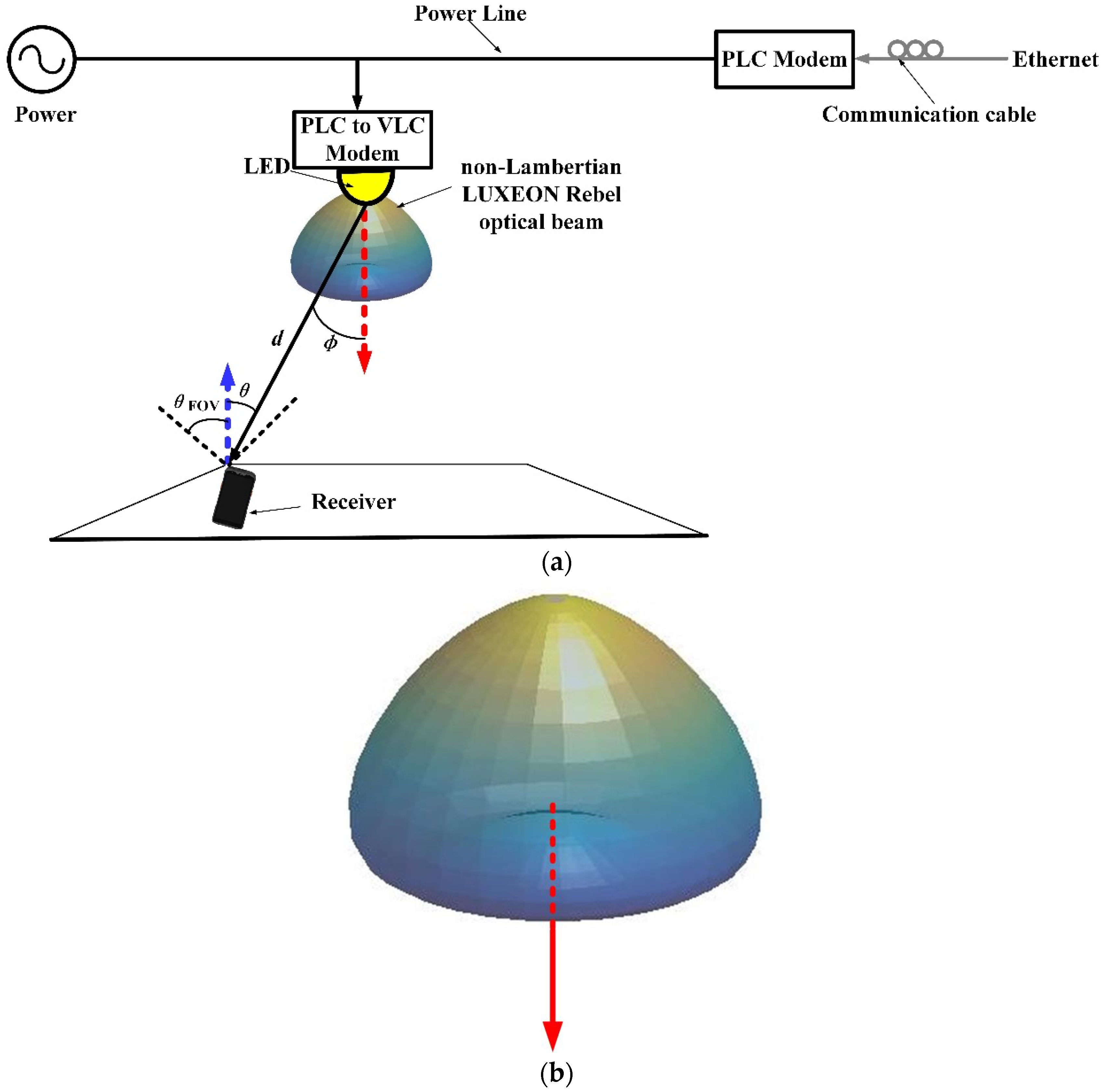
2.2. Hybrid Channel Based on Distinct Non-Lambertian Optical Beam Configuration

Different from the well-discussed Lambertian beam, the spatial radiation intensity of non-Lambertian beams provides distinct spatial selectivity for the emitted optical signal [23,24]. Without a loss of generality, as one representative non-Lambertian optical emission beam with rotational symmetry, the counterpart from the LUXEON Rebel LED was deliberately selected for the investigation of a hybrid PLC and VLC channel in this subsection. The considerations for this choice are that, on one hand, this emission beam presents with quite different spatial radiation characteristics compared with the general Lambertian optical emission beams, while on the other hand, this non-Lambertian emission beam is generated by a commercially available LED, which makes this article applicable for implementation in ubiquitous engineering scenarios.
In one representative indoor hybrid PLC and VLC scenario, when the radiation characteristic is introduced from the LUXEON Rebel non-Lambertian beam, the resulting LUXEON non-Lambertian VLC channel gain at the receiver can be written as follows:
H VLC Rebel f = η LOS Rebel e j 2 π f Δ t LOS + η DIFF e j 2 π f Δ t DIFF 1 + j f / f C ,
where η LOS Rebel denotes the optical channel gain of the LUXEON non-Lambertian LOS signal. Under this LUXEON non-Lambertian beam pattern configuration, the LOS optical channel gain should be specifically represented by the following:
η LOS Rebel = A R P normRebel d 2 I Rebel ϕ cos θ ,               0 θ θ FOV                   0 ,                                                                               θ 0 > θ FOV ,
where P normRebel is the normalization factor for the LUXEON Rebel emission beam, which ensures that the sum power radiated across the whole of the spatial directions is 1 W, and I Rebel ϕ denotes the intensity of the LUXEON Rebel emission beam, which can be profiled by one sum of Gaussian functions [23,24]:
I Rebel ( ϕ ) = k = 1 N 1 g 1 k Rebel exp ln 2 ϕ g 2 k Rebel g 3 k Rebel 2 ,
where ϕ denotes the emission angle, and N1 = 2 is the number of Gaussian functions. Specifically, the values of coefficients in this expression are as follows: g 11 Rebel = 0.76, g 21 Rebel = 0°, g 31 Rebel = 29°, g 12 Rebel = 1.10, g 22 Rebel = 45°, and g 32 Rebel = 21°. Figure 2 illustrates the 3D beam patterns of this LUXEON Rebel non-Lambertian optical beam with rotational symmetry from a side view. Unlike the previous Lambertian optical beam, in this non-Lambertian case, the maximum emission intensity does not appear in the normal direction, i.e., at the direction of the red arrow anymore, but at all directions with an irradiance angle of about 40°.
By substituting (11) into (10), the LUXEON (Lumileds, San Jose, CA, USA) non-Lambertian LOS optical channel gain for this hybrid PLC and VLC can be renewed as:
η LOS Rebel   = A R P normRebel d 2 k = 1 N 1 g 1 k Rebel exp ln 2 ϕ g 2 k Rebel g 3 k Rebel 2 cos θ ,                   0 θ θ FOV               0 ,                                                                                                                                                                                                               θ 0 > θ FOV .
Overall, the final hybrid PLC and VLC channel, based on LUXEON non-Lambertian optical beam configuration for one certain receiver, is represented by the superposed effects of all the LUXEON non-Lambertian LED optical sources and can be given by the following:
H Rebel f = i = 1 N LED H i , PLC f H i , VLC Rebel f ,
where H i , PLC f denotes the PLC channel between the PLC modulator and the i-th LED optical source, H i , VLC Rebel f represents the VLC channel between the i-th LUXEON non-Lambertian LED optical source and the optical receiver, and N LED represents the number of the LED sources that the optical receiver can detect.
As a matter of fact, unlike the Lambertian emission beam and the LUXEON Rebel optical beam, the radiation pattern of the NSPW345CS Nichia LED (Nichia, Tokushima, Japan) is not rotationally symmetric anymore. Thanks to this novel beam asymmetry, the non-Lambertian NSPW345CS Nichia LED was adopted for the following exploration of a hybrid channel based on the non-Lambertian emission beam in this subsection. Obviously, the NSPW emission beam can provide a much more novel spatial radiation characteristic when compared with the baseline Lambertian emission beam, and this asymmetric emission beam, from a representative commercially available LED, can assure that the following work is applicable for future implementation as well.
In one typical indoor hybrid PLC and VLC scenario, when the radiation characteristics of the optical source follow the NSPW non-Lambertian beam, the channel gain of the NSPW non-Lambertian VLC at the receiver could be given as follows:
H VLC NSPW f = η LOS NSPW e j 2 π f Δ t LOS + η DIFF e j 2 π f Δ t DIFF 1 + j f / f C ,
where η LOS NSPW denotes the optical wireless channel gain of the NSPW LOS signal. Under this NSPW emission beam configuration, the LOS channel gain should be specifically represented by the following:
η LOS NSPW = A R P normNSPW d 2 I NSPW ( ϕ , α ) cos θ ,                   0 θ θ FOV             0 ,                                                                                                                 θ 0 > θ FOV ,
where P normNSPW denotes the normalization factor of the asymmetric NSPW emission beam, which ensures that the power radiated across the whole of the spatial directions is 1 W, and I NSPW ( ϕ , α ) is the spatial radiation intensity of the asymmetric NSPW emission beam, which is profiled by the following equation as one sum of multiple Gaussian functions [23,24]:
I NSPW ( ϕ , α ) = m = 1 2 g 1 m exp In 2 ( ϕ g 2 m ) 2 cos 2 α ( g 3 m ) 2 + sin 2 α ( g 4 m ) 2 ,
where α is the azimuth angle, and the coefficient values in the Gaussian functions are written as g 11 NSPW = 0.13, g 21 NSPW = 45°, g 31 NSPW = g 41 NSPW = 18°, g 12 NSPW = 1, g 22 NSPW = 0, g 32 NSPW = 38°, and g 42 NSPW = 22°. Similarly, the 3D display of the NSPW345CS UB light beam is illustrated in Figure 3. By substituting (16) into (15), the asymmetric NSPW optical wireless channel gain for this hybrid PLC and VLC could be renewed as follows:
η LOS NSPW = A R P normNSPW d 2 m = 1 2 g 1 m exp In 2 ( ϕ g 2 m ) 2 cos 2 α ( g 3 m ) 2 + sin 2 α ( g 4 m ) 2 × cos θ ,                                                                                                                                                 0 θ θ FOV             0 ,                                                                                                                                                                     θ 0 > θ FOV .
Overall, the final hybrid PLC and VLC channel, based on an asymmetric NSPW non-Lambertian emission beam for one certain receiver, is represented by the superposed effects of all the asymmetric NSPW non-Lambertian LED optical sources and can be given by the following:
H NSPW f = i = 1 N LED H i , PLC f H i , VLC NSPW f ,
where H i , PLC f denotes the PLC channel between the PLC modulator and the i-th LED optical source, H i , VLC NSPW f represents the VLC channel between the i-th NSPW non-Lambertian LED optical source and the optical receiver, and N LED represents the number of the involved LED sources that the optical receiver can detect. It must be noted that, in this work, for the convenience of analysis, the discussion is limited to a single LED optical source situation, i.e., N LED = 1. The more complicated scenarios, with multiple distributed LED optical sources, are left for investigation in future work.

3. Numerical Evaluation

In this section, a numerical analysis was accomplished for the channel characteristics of hybrid PLC and VLC based on the conventional Lambertian emission beam configuration and the emerging non-Lambertian emission beam configuration. In addition to the abovementioned performance metrics, the overall achievable data rate was also adopted to comparatively evaluate the transmission performance of the investigated hybrid PLC and VLC channels based on distinct optical beam configurations, which is the sum of all achievable data rates from all available subcarriers. The specific expression can be given as follows:
R PLC - VLC = j = 1 M B sub 2 log 2 1 + exp ( 1 ) 2 π P T γ PD s LED H PLC - VLC f j 2 P N ,
where M is the number of subcarriers and B sub denotes the subcarrier bandwidth. A scaling factor of one-half is included, since a spectral efficiency reduction is induced by the signal processing of Hermitian symmetry, to match the inherent limitations to optical intensity modulation of the VLC portion of this hybrid system. Moreover, P T denotes the power allocated to each subcarrier in the electrical domain, P N denotes the noise power to each subcarrier, γ PD denotes the photodiode responsivity at the optical receiver of the VLC portion, and s LED denotes the LED conversion factor from the electrical domain to the optical domain. For the convenience of the investigation, the transmitted signal–noise ratio (SNR) is inherited as the figure of merit to evaluate the relevant transmission performance differences between the hybrid PLC and VLC channels of concern, with distinct beam configurations, which is defined in decibels (dB) and specifically given as follows:
SNR T = 10 log 10 P T P N ,
Specifically, one typical medium-sized empty room was considered, which is consistent with Figure 1a, Figure 2a and Figure 3a. In addition, the main parameters involved for the hybrid PLC and VLC wireless system for a 6G IoT network are included in Table 1.
Here, as for the Lambertian emission beam, the Lambertian index is set as 1 without a loss of generality. The above table summarizes a typical PLC channel with six paths over 30 MHz frequency range, which is consistent with [12]. In the following numerical evaluations, one LED optical transmitter was mounted on the ceiling at the center of the room with the orientation facing towards the floor. The PD-based optical receiver was located along the desktop plane with a straight-upward orientation.

3.1. Channel Frequency Response

To investigate the effect of the receiver position on the channel frequency response characteristics of the hybrid PLC and VLC, three typical receiver position settings, i.e., a central position (2.5, 2.5, 0.85) m, side position (2.5, 0.5, 0.85) m, and corner position (0.5, 0.5, 0.85) m were introduced to the hybrid PLC and VLC systems with distinct optical beam configurations, as is shown in Figure 4. Due to the unique rotational asymmetry of the NSPW non-Lambertian optical beam, one additional position, i.e., a side position 2 (0.5, 2.5, 0.85) m was introduced for the receptive analysis.
For the case of the central receiver position, the direct current (DC) hybrid channel gain is about −52.4 dB, −54.3 dB, and −49.4 dB for the baseline Lambertian optical beam configuration, LUXEON Rebel non-Lambertian optical beam configuration, and NSPW non-Lambertian optical beam configuration, and the according frequency response dynamic range is about 9.09 dB (i.e., −61.5 dB~−52.4 dB), 10.0 dB (i.e., −64.3 dB~−54.3 dB), and 8.5 dB (i.e., −57.9 dB~−49.4 dB), with two frequency response notches that appear at about 10 MHz and 15 MHz. Once the receiver was removed to the side position, the gain metric of this DC hybrid channel was reduced to about −56.3 dB, −55.8 dB, and −57.5 dB, for discussed three configurations, while the dynamic range of the relevant frequency response was about 11.8 dB (i.e., −68.1 dB~−56.3 dB), 11.1 dB (i.e., −66.9 dB~−55.8 dB), and 14.0 dB (i.e., −71.5 dB~−57.5 dB). Note that unlike the baseline Lambertian optical beam configuration and LUXEON Rebel non-Lambertian optical beam configuration, the frequency response at the side position 2, i.e., (0.5, 2.5, 0.85) m for the NSPW non-Lambertian beam configuration, provided a superior response amplitude, thanks to the rotated asymmetrical pattern of the NSPW beam. The relevant gain metric of the DC hybrid channel increased to about −55.0 dB and the respective dynamic range of the frequency response was about 10.4 dB (i.e., −65.4 dB~−55.0 dB).
Once the optical receiver was further removed into the corner position, the gain performance method of the DC hybrid channel was further reduced to about −58.0 dB, −57.6 dB, and −58.6 dB for the three beam configurations of concern, while the relevant dynamic range of the frequency response was about 15.2 dB (i.e., −73.2 dB~−58.0 dB), 14.0 dB (i.e., −71.6 dB~−57.6 dB), and 22.2 dB (i.e., −80.8 dB~−58.6 dB), which verifies the superiority of the LUXEON Rebel beam in mitigating depth fading.
To sufficiently eliminate the potential mutual interference between the alternating current (AC) and the information signal on the power line, in the following work, subcarriers between 0.1 MHz and 25 MHz were utilized to carry the data transmission, which was quite close to the frequency band setting from the work in [11]. For the convenience of the analysis, the subcarrier frequency spacing was 0.5 MHz, as is shown in Figure 4.

3.2. Achievable Rate Performance

In this section, we investigated the achievable rate performance of the hybrid PLC and VLC channels by applying different optical beam configurations. Figure 5 shows the achievable rate versus the transmitted power when applying distinct optical beam configurations at different receiver positions. For the case of the baseline Lambertian optical beam configuration, when the transmitted power is increased to 50 W from the original 5 W, the achievable rates are increased from 152.5 Mbps to 194 Mbps for the central position, while the counterpart of the corner position is enhanced to 118 Mbps from the original 77.3 Mbps. As for the side position, the achievable rate was accordingly increased to 147.8 Mbps from the original 106.4 Mbps. This means that, for the Lambertian optical beam configuration, although the transmitted power is increased to 50 W, the fluctuation range of the achievable rate (i.e., the rate difference between the maximum and minimum among all concerned positions for one certain transmitted power) varied slightly, increasing to 76 Mbps from the original 75.2 Mbps.
On the other hand, as is shown in Figure 5b, once the LUXEON Rebel non-Lambertian optical beam configuration was applied, even for the central receiver position, the original achievable rate was just 131.9 Mbps; when the available transmitted power was increased to 50 W, this transmission rate gradually increased to 173.4 Mbps. As for the corner position, this counterpart was respectively enhanced to 127.3 Mbps from the original 86.2 Mbps. A similar trend could be observed for the side position, where the achievable rate was enhanced to 155.3 Mbps from the original 113.8 Mbps. From the view of the fluctuation range of the achievable rate, this performance metric was changed to 46.1 Mbps from the original 45.7 Mbps. Based on the above analysis, it could be identified that, for the hybrid PLC and VLC channel, the LUXEON Rebel non-Lambertian optical beam configuration could steadily achieve a reduction of about 29.5 Mbps in the fluctuation of the achievable rate, which means that a much more uniform transmission coverage could be derived by using the LUXEON Rebel non-Lambertian optical beam configuration.
Finally, once the NSPW non-Lambertian optical beam configuration was applied to the constructed hybrid PLC and VLC channel, for the central receiver position, the original achievable rate could be up to 180.1 Mbps; when the transmitted power was further increased to 50 W, this transmission rate gradually increased to 222.4 Mbps, which indicates that a rate gain of about 28 Mbps can be achieved compared with the baseline Lambertian optical beam configuration. A similar trend could be observed for the side position, where the achievable rate was enhanced to 127.8 Mbps from the original 86.6 Mbps. Thanks to the inherent rotational asymmetry of the NSPW non-Lambertian optical beam configuration, the other nearby side position (i.e., side position 2) could achieve an original rate of 124.2 Mbps. This performance metric could be increased to 165.7 Mbps, which means that a rate gain of about 17.8 Mbps could be provided by the LUXEON Rebel non-Lambertian optical beam configuration. At the same time, it should be noted that for the more challenging corner position, the original achievable rate is just 64.7 Mbps. Although it could be further scaled to 102.1 Mbps, the rate loss is more than about 21.5 Mbps compared with the respective metrics of the baseline Lambertian optical beam configuration. In addition, the obvious degradation in the fluctuation range of the achievable rate, up to more than 115.4 Mbps, could be identified for the case of the NSPW non-Lambertian optical beam configuration, with an intensification of the rate fluctuation of about 39.4 Mbps compared to the baseline Lambertian case.

3.3. Effect of Azimuth Rotation

Finally, the effect of beam azimuth direction for the integrated PLC and VLC transmission channel was investigated. Intuitively, the baseline Lambertian emission beam and the Rebel non-Lambertian emission beam are omnidirectional and symmetric, therefore any manipulated azimuth rotation to the ceiling-mounted LED optical source will not induce variation to the received signal strength for any position on the working plane of the receiver. On the contrary, the NSPW non-Lambertian optical beam is not omnidirectional or symmetric anymore, and could provide apparent spatial azimuth selectivity. For the convenience of the discussion, the projection of the wide side cross-section of this typical rotating asymmetric beam on the ceiling plane was utilized to indicate the original horizontal azimuth orientation. When the additional horizontal azimuth rotation is introduced to the asymmetric LED beam, the transmission performance of this hybrid channel will be differentially varied according to the spatial position of the individual receiver. In Figure 6, a comparison of the achievable rates versus the azimuth rotation angle is illustrated. Since the NSPW non-Lambertian optical beam can match the axisymmetric emission pattern around the normal axis of the LED, the specific spatial beam radiation, manipulated by the horizontal azimuth rotation of 180°, can perfectly overlap with the initial spatial beam radiation without any horizontal azimuth rotation. Based on this rotation periodicity, the discussed range of horizontal azimuth rotation was between 0° and 180°. As is shown in Figure 6, the effect of the above horizontal azimuth rotation on the superior channel transmission performance of the central receiver position, was attributable to its dependence on the horizontal azimuth rotation on the axis direction of the LED source. Nevertheless, for the side position, the respective achievable rate is significantly affected by the azimuth rotation angle. Up to 37.7 Mbps of rate gain can be obtained by a 90° horizontal azimuth rotation, which makes the asymmetric beam horizontally oriented to the side position. At the same time, for the side position 2, the 90° horizontal azimuth rotation led to about 37.7 Mbps of rate loss from the original achievable transmission performance of almost 136.6 Mbps, due to the orthogonal orientation of horizontal beam with respect to the candidate receiver position. As for the corner position, a similar phenomena can be observed when the azimuth rotation is up to about 30° or 60°, as the relevant achievable rate is increased to about 96.6 Mbps from the initial 75.4 Mbps.
As for the 6G aspect, actually, various popular VLC styles, including hybrid PLC and VLC, are being actively explored in multiple typical application scenarios as one important technique for enabling the future-oriented LED infrastructure-based 6G IoT Network. It must be noted that the coming 6G IoT Network must face the distinct LED infrastructures with customized designs for various lighting targets, but LED infrastructures with conventional Lambertian beam configurations are not well discussed. Therefore, as the main contribution of this work, research on the channel characteristics of hybrid PLC and VLC based on distinct optical beam configurations is essential and fundamental for paving the way to applying VLC, especially hybrid PLC and VLC, in the coming 6G IoT Network.

4. Conclusions

This work is motivated by the limitations of the Lambertian emission beam configuration-based conventional hybrid PLC and VLC techniques paradigm, which fail to cover the investigations of hybrid PLC and VLC based on distinct emission beam configurations. In this article, commercially available optical sources with distinct non-Lambertian beam patterns were employed to configure the novel hybrid PLC and VLC system and the relevant channel characteristics were explored for a future 6G IoT Network as well. For the typical side receiver position under a NSPW non-Lambertian configuration, the achievable transmission performance of the hybrid PLC and VLC channel is up to 165.7 Mbps, while the counterpart of the baseline Lambertian hybrid PLC and VLC configuration is just about 147.8 Mbps accordingly. In future work for the 6G IoT network, the exploration of hybrid PLC and VLC based on distinct optical beams could be extended to customized dynamic beam configurations, beam switching, beam steering, resource allocation, reconfigurable multiple-input multiple-output, and other design-enabling techniques.

Author Contributions

J.D., Determined the theme and structure of the article, provided professional knowledge in the field of visible light communications, wrote and modified the article, and replied to comments from the editors and reviewers; C.-L.I., Provided theoretical knowledge of mobile communication and wireless communication; J.W., Found the literature, participated in the discussion and writing of some of the content; J.S., Looked for the literature, participated in the discussion and writing of some of the content. All authors have read and agreed to the published version of the manuscript.

Funding

This work was supported in part by the National Natural Science Foundation of China (Grants No. 62061043), the Tianshan Cedar Project of Xinjiang Uygur Autonomous Region (Grants No. 2020XS27) and the High-level Talents Introduction Project in Autonomous Region (Grants No. 042419004).

Institutional Review Board Statement

Not applicable.

Informed Consent Statement

Not applicable.

Data Availability Statement

Data are contained within the article.

Conflicts of Interest

The authors declare no conflict of interest.

References

  1. Zhang, Y.; Zhang, H.; Cosmas, J.; Jawad, N.; Ali, K.; Meunier, B.; Kapovits, A.; Huang, L.-K.; Li, W.; Shi, L.; et al. Internet of radio and light: 5G building network radio and edge architecture. Intell. Converg. Netw. 2020, 1, 37–57. [Google Scholar] [CrossRef]
  2. Chowdhury, M.Z.; Hossan, M.T.; Islam, A.; Jang, Y.M. A comparative survey of optical wireless technologies: Architectures and applications. IEEE Access 2018, 6, 9819–9840. [Google Scholar] [CrossRef]
  3. Sun, S.; Yang, F.; Song, J. Sum rate maximization for intelligent reflecting surface-aided visible light communications. IEEE Commun. Lett. 2021, 25, 3619–3623. [Google Scholar] [CrossRef]
  4. Sun, S.; Wang, T.; Yang, F.; Song, J.; Han, Z. Intelligent reflecting surface-aided visible light communications: Potentials and challenges. IEEE Veh. Technol. Mag. 2022, 17, 47–56. [Google Scholar] [CrossRef]
  5. Wang, T.; Yang, F.; Song, J.; Han, Z. Dimming Techniques of Visible Light Communications for Human-Centric Illumination Networks: State-of-the-Art, Challenges, and Trends. IEEE Wirel. Commun. 2020, 27, 88–95. [Google Scholar] [CrossRef]
  6. Ma, S.; Zhang, F.; Zhou, F.; Wang, Y.; Li, S. Simultaneous Lightwave Information and Power Transfer in Visible Light Communication Systems. IEEE Trans. Wirel. Commun. 2019, 18, 5818–5830. [Google Scholar] [CrossRef]
  7. Hamza, A.S.; Deogun, J.S.; Alexander, D.R. Classification framework for free space optical communication links and systems. IEEE Commun. Surveys Tuts. 2019, 21, 1346–1382. [Google Scholar] [CrossRef]
  8. Ma, X.; Yang, J.G.F.; Ding, W.; Yang, H.; Song, J. Integrated Power Line and Visible Light Communication System Compatible with Multi-Service Transmission. IET Commun. 2017, 11, 104–111. [Google Scholar] [CrossRef]
  9. Gao, J.; Yang, F.; Ding, W. Novel Integrated Power Line and Visible Light Communication System with Bit Division Multiplexing. In Proceedings of the 2015 International Wireless Communications and Mobile Computing Conference, Dubrovnik, Croatia, 24–28 August 2015; IEEE: New York, NY, USA, 2015. [Google Scholar]
  10. Ma, X.; Ding, W.; Yang, F.; Yang, H.; Song, J. A Positioning Compatible Multi-Service Transmission System Based on the Integration of VLC and PLC. In Proceedings of the 2015 International Wireless Communications and Mobile Computing Conference, Dubrovnik, Croatia, 24–28 August 2015; IEEE: New York, NY, USA, 2015. [Google Scholar]
  11. Feng, S.; Bai, T.; Hanzo, L. Joint Power Allocation for the Multi-User NOMA-Downlink in a Power-Line-Fed VLC Network. IEEE Trans. Veh. Technol. 2019, 68, 5185–5190. [Google Scholar] [CrossRef]
  12. Ding, W.; Yang, F.; Yang, H.; Wang, J.; Wang, X.; Zhang, X.; Song, J. A hybrid power line and visible light communication system for indoor hospital applications. Comput. Ind. 2015, 68, 170–178. [Google Scholar] [CrossRef]
  13. Song, J.; Ding, W.; Yang, F.; Yang, H.; Yu, B.; Zhang, H. An Indoor Broadband Broadcasting System Based on PLC and VLC. IEEE Trans. Broadcast. 2015, 61, 299–308. [Google Scholar] [CrossRef]
  14. Li, D.; Hu, Y.; Zhang, G.; Pan, C.; Yang, H.; Song, J. An integrated indoor VLC+PLC system for video broadcast and positioning. In Proceedings of the 2021 International Conference Engineering and Telecommunication (En&T), Moscow, Russia, 24–25 November 2021; IEEE: New York, NY, USA, 2021. [Google Scholar]
  15. Yan, Y.; Ding, W.; Yang, H.; Song, J. The video transmission platform for The PLC and VLC integrated system. In Proceedings of the 2015 IEEE International Symposium on Broadband Multimedia Systems & Broadcasting, Ghent, Belgium, 3–5 April 2015; IEEE: New York, NY, USA, 2015. [Google Scholar]
  16. Baig, S.; Asif, H.M.; Umer, T.; Mumtaz, S.; Shafiq, M.; Choi, J.G. High data rate discrete wavelet transform-based plc-vlc design for 5G communication systems. IEEE Access 2018, 6, 52490–52499. [Google Scholar] [CrossRef]
  17. Liu, H.; Zhu, P.; Chen, Y.; Huang, M. Power Allocation for Downlink Hybrid Power Line and Visible Light Communication System. IEEE Access 2020, 6, 24145–24152. [Google Scholar] [CrossRef]
  18. Ma, H.; Lampe, L.; Hranilovic, S. Hybrid Visible Light and Power Line Communication for Indoor Multiuser Downlink. J. Opt. Commun. Netw. 2017, 9, 635–647. [Google Scholar] [CrossRef]
  19. Gao, S.; Zhang, J.; Song, J.; Yang, H. Random channel generator of the integrated power line communication and visible light communication. In Proceedings of the 2017 IEEE International Symposium on Power Line Communications and its Applications (ISPLC), Madrid, Spain, 3–5 April 2017; IEEE: New York, NY, USA, 2017. [Google Scholar]
  20. Nlom, S.; Ndjiongue, A.; Ouahada, K. Cascaded PLC-VLC Channel: An Indoor Measurements Campaign. IEEE Access 2018, 6, 25230–25239. [Google Scholar] [CrossRef]
  21. Nlom, S.M.; Ndjiongue, A.R.; Ouahada, K.; Ferreira, H.C.; Shongwe, T. A simplistic channel model for cascaded PLC-VLC systems. In Proceedings of the IEEE ISPLC 2017—2017 IEEE International Symposium on Power Line Communications & Its Applications, Madrid, Spain, 3–5 April 2017; IEEE: New York, NY, USA, 2017. [Google Scholar]
  22. Komine, T.; Nakagawa, M. Fundamental analysis for visible-light communication system using LED lights. IEEE Trans. Consum. Electron. 2004, 50, 100–107. [Google Scholar] [CrossRef]
  23. Moreno, I.; Sun, C.-C. Modeling the radiation pattern of LEDs. Opt. Exp. 2008, 16, 1808–1819. [Google Scholar] [CrossRef]
  24. Ding, J.; Chih-Lin, I.; Xu, Z. Indoor optical wireless channel characteristics with distinct source radiation patterns. IEEE Photonics J. 2016, 8, 1–15. [Google Scholar] [CrossRef]
  25. Zimmermann, M.; Dostert, K. A multipath model for the powerline channel. IEEE Trans. Commun 2002, 50, 553–559. [Google Scholar] [CrossRef]
  26. Ding, J.; I, C.-L.; Wang, J.; Yang, H. Effects of Optical Beams on MIMO Visible Light Communication Channel Characteristics. Sensors 2022, 22, 216. [Google Scholar] [CrossRef] [PubMed]
Figure 1. Schematic of hybrid PLC and VLC based on baseline Lambertian emission beam for the coming 6G IoT network: (a) the respective application scenario, (b) the respective 3D illustration of beam pattern.
Applsci 14 07481 g001
Figure 2. Schematic of hybrid PLC and VLC based on LUXEON Rebel optical emission beam for the coming 6G IoT network: (a) the respective application scenario, (b) the respective 3D illustration of beam pattern.
Applsci 14 07481 g002
Figure 3. Schematic of hybrid PLC and VLC based on asymmetric NSPW optical emission beam for the coming 6G IoT network: (a) the respective application scenario, (b) the respective 3D illustration of beam pattern from a wide side view, (c) the respective 3D illustration of beam pattern from a narrow side view.
Applsci 14 07481 g003
Figure 4. Hybrid PLC and VLC channel frequency response comparisons for typical receiver positions with distinct optical beam configurations: (a) baseline Lambertian optical beam configuration, (b) LUXEON Rebel non-Lambertian optical beam configuration, and (c) NSPW non-Lambertian optical beam configuration.
Applsci 14 07481 g004
Figure 5. Comparison of achievable rate versus transmitted power of hybrid PLC and VLC channel: (a) baseline Lambertian optical beam configuration, (b) LUXEON Rebel non-Lambertian optical beam configuration, and (c) NSPW non-Lambertian optical beam configuration.
Applsci 14 07481 g005
Figure 6. Comparison of achievable rate versus azimuth rotation angle for hybrid PLC and VLC channel with typical rotating asymmetric beam configuration.
Applsci 14 07481 g006
Table 1. Configuration of main parameters.
ParametersValues
Room size (W × L × H)5 × 5 × 3 m3
Number of transmitter1
Location of transmitter(2.5, 2.5, 3) m
LED Lambertian index1
LED conversion factor0.44 W/A
Photodiode responsivity0.30 A/W
Subcarrier bandwidth0.5 MHz
Number of subcarriers40
Receiver field of view90°
Height of receiving plane0.85 m
Physical area of PD1.0 cm2
Delay τ 1 0.33 μs
Delay τ 2 0.5 μs
Delay τ 3 0.54 μs
Delay τ 4 0.58 μs
Delay τ 5 0.6 μs
Delay τ 6 1.2 μs
Weighting factor g 1 0.54
Weighting factor g 2 0.275
Weighting factor g 3 −0.15
Weighting factor g 4 0.08
Weighting factor g 5 −0.03
Weighting factor g 6 −0.02
Exponent of the attenuation factor k1
Attenuation parameter α 0 −2.1 × 10⁻³
Attenuation parameter α 1 8.1 × 10⁻¹⁰
Disclaimer/Publisher’s Note: The statements, opinions and data contained in all publications are solely those of the individual author(s) and contributor(s) and not of MDPI and/or the editor(s). MDPI and/or the editor(s) disclaim responsibility for any injury to people or property resulting from any ideas, methods, instructions or products referred to in the content.

