Article

CNN-Based Damage Identification of Submerged Structure-Foundation System Using Vibration Data

Department of Ocean Engineering, Pukyong National University, 45 Yongso-ro, Nam-gu, Busan 48513, Republic of Korea
*
Author to whom correspondence should be addressed.
Appl. Sci. 2024, 14(17), 7508; https://doi.org/10.3390/app14177508
Submission received: 31 July 2024 / Revised: 22 August 2024 / Accepted: 23 August 2024 / Published: 25 August 2024
(This article belongs to the Special Issue Artificial Intelligence in Fault Diagnosis and Signal Processing)

Abstract

:
This study presents a convolutional neural network (CNN) deep learning approach for identifying damage in submerged structure-foundation systems using vibration data. Firstly, foundation damage in a lab-scale caisson-foundation system is simulated to measure time-history responses. Singular value decomposition (SVD) responses are derived from the time-history responses. Secondly, the 1-D CNN deep learning model is trained using both the time-history responses and SVD responses. Finally, the trained CNN models are implemented to evaluate the foundation damage under conditions of noise contamination and partially untrained data. The experimental results demonstrate the effectiveness of CNN models for damage identification and highlight the comparative strengths of time-history and SVD data. The CNN model trained using SVD data outperforms the other model when under noise contamination conditions, while the CNN model trained using time-history data maintains better accuracy in partially untrained data conditions. Integrating both types of data enhances the accuracy of damage classification.

1. Introduction

Submerged structure-foundation systems, such as caisson breakwater systems, face significant challenges from extreme conditions like earthquakes and storm surges over their operational lifespan [1]. Caisson systems consist of an above-water concrete cap, the submerged caisson, and the foundation. Over time, several issues can develop in the foundation, such as settlement, overturning, and sliding [2,3]. Additionally, the caisson can suffer from large storm surges, causing severe cracking and material leakage [4]. Due to the inaccessibility of underwater components, innovative evaluation methods are required to assess their structural integrity.
Among several structural health monitoring techniques, vibration-based monitoring has emerged as an effective method for assessing the damage in submerged structures [5,6,7]. Most studies have focused on manual damage identification using vibration features [8,9,10]. Vibration features are complicated and are affected by foundation conditions and environmental factors [11,12]. As a result, assessing submerged structure-foundation systems has remained challenging due to the uncertainties associated with field parameters. Further research is needed to address these complexities and improve the reliability of structural integrity assessments.
Recent studies have demonstrated the effectiveness of 1-D convolutional neural networks (CNNs) in real-time applications and the ability to learn complex tasks. Such 1-D CNN models can be trained using vibration features such as singular value decomposition (SVD) and time-history responses. SVD data are obtained from multiple preprocessing steps for each damage level [13]. As an alternative approach, time-history responses from accelerometers can be directly utilized for the CNN model, bypassing several preprocessing steps, thereby enhancing speed and reducing computational costs [14,15,16].
There has been a lack of research comparing CNN models trained using different vibration features, and investigating how integrating results could improve prediction performance. This study uses both time-history responses and SVD responses for the CNN model. The advantages and disadvantages of each type of training data are identified by evaluating the CNN model under noise contamination and partially untrained data conditions. The main contributions of this study are as follows:
  • A CNN deep learning approach is developed to identify damage in submerged structure-foundation systems using both time-history and SVD data.
  • The performance of the CNN model is evaluated with partially untrained cases, where certain damage levels were excluded from the training and validation datasets.
  • A comparative study between CNN trained using time-history and SVD data is conducted. The results from the two models are integrated to strengthen the damage classification performance.
To achieve these objectives, a CNN deep learning approach for identifying damage in submerged structure-foundation systems using both time-history and SVD data is developed. Firstly, foundation damage in a lab-scale caisson-foundation system is simulated to measure time-history responses. SVD responses are derived from the time-history responses. Secondly, the 1-D CNN deep learning model is trained using both the time-history responses and SVD responses. Finally, the trained CNN models are implemented to evaluate the foundation damage under conditions of noise contamination and partially untrained data.

2. Literature Reviews

2.1. Vibration-Based Techniques for Caisson-Foundation Systems

Many researchers have utilized vibration-based techniques to handle the transient interactions between waves, structures, and foundations [3,8]. For caisson-foundation structures, vital structural information can be obtained from a few sensors strategically placed in the small above-water section [5,6,7]. Ming et al. [17] studied the dynamic response of a caisson breakwater using a rigid body on an elastic foundation model under wave action. Lee et al. [8] employed vibration-based methods to detect damage at the interface between the caisson and the foundation. Huynh et al. [9,10] combined simplified analytical approaches with in situ vibration measurements to assess caisson-foundation system integrity. Lee et al. [11,12] developed a practical scheme to differentiate the impact of foundation conditions and environmental factors on the vibration characteristics of the breakwater system. Pham et al. [13] proposed the pseudo-wave method superposing the vibration responses from several man-made excitations to simulate the wave impact on the caisson system.

2.2. 1-D CNN Deep Learning and Data Acquisition

The compact 1-D CNN excels in extracting features from vibration data with minimal training required [18,19]. The vibration data (i.e., time-history and SVD responses) are one-dimensional arrays with inherent order. The 1-D CNN model is suitable for processing 1-D and sequential input data, as it can effectively learn the ordered patterns by capturing local dependencies. Teng et al. [14] applied 1-D CNNs trained using vibration signals from a numerical model to detect damage in a steel bridge. Huang et al. [15] employed a CNN model to quantify the dynamic stiffness of railway tracks using vibration data. Li et al. [16] implemented an adaptive CNN model for bearing-fault diagnosis in noisy environments.
The vibration data for the CNN model can be obtained by two approaches. In the first approach, vibration data are collected directly from damaged caissons after extreme events such as storms or tsunamis. These data are labeled according to the severity of the damage and used for training. In the second approach, vibration data are collected indirectly through foundation damage simulation. Pham et al. [13] proposed a method called pseudo-damage simulation, where concrete weights were applied on top of the caisson to mimic the effect of foundation damage. In their study, experiments were conducted under laboratory conditions. The location, shape, and severity of foundation damage levels were predetermined.

3. Methodology

3.1. Research Framework

Detecting damage using conventional methods is challenging due to the complexity of the responses. The 1-D CNN approach can be practical to overcome this challenge. The 1-D CNN method trained using vibration data (i.e., time-history and SVD responses) is applied to automate the feature extraction process and to facilitate real-time monitoring.
Figure 1 illustrates the CNN deep learning model scheme for caisson-foundation system using vibration data. This scheme comprises three phases: (1) data acquisition via the vibration technique, (2) construction of the 1-D CNN model for the caisson-foundation system, and (3) evaluation of the 1-D CNN model. In Phase 1, the databanks corresponding to foundation damage on the caisson system are generated for deep learning models. The foundation damage simulation involves removing a certain amount of sand and gravel from the existing foundation. The vibration data (i.e., time-history and SVD responses) are acquired by accelerometers under man-made excitation. The time-history responses obtained from several accelerometers are concatenated to form one continuous response. The SVD responses are derived from the time-history responses using the frequency domain decomposition (FDD) method. The vibration data are processed with data augmentation to form a databank and used for the CNN model in the subsequent phases.
In Phase 2, a 1-D CNN model is developed to detect damage in the caisson-foundation system. The databank is augmented by introducing noise to the vibration. The 1-D CNN model processes the vibration data through several hidden layers to classify the damage levels in the foundation. In Phase 3, the effectiveness of the 1-D CNN model is evaluated for noise-contaminated and untrained damage cases.

3.2. Vibration-Data Acquisition Technique

3.2.1. Vibration Monitoring Method

Figure 2 illustrates a vibration monitoring setup on a submerged caisson-foundation system. This system has three main components: an above-water concrete cap, a submerged caisson, and a foundation. The foundation is constructed with a sand mound and gravel armor. The caisson is oriented perpendicular to the direction of wave propagation and is subjected to impulsive breaking wave forces. The vibration test for in situ submerged caisson-foundation systems uses wave forces as the excitation source. Alternatively, a tugboat with adjustable weight and speed can be used to generate controlled artificial excitation for the vibration tests.
Figure 3 illustrates vibration monitoring for a caisson-foundation system. Several accelerometers are strategically installed on the above-water concrete cap of the caisson to obtain vibration data. These accelerometers are oriented in three directions (x, y, and z) to capture all caisson motions, including heave, sway, and roll. In this study, the time-history responses are acquired by five accelerometers (i.e., ACC 1z, ACC 2z, ACC 2x, ACC 3x, and ACC 2y) for 15 s at a sampling rate of 1 kHz. Only 1000 data points that contain the most important information (i.e., 100 data points before the impact load and 900 data points after) are chosen. These time-history responses from the five sensors are then concatenated to form one continuous response, as shown in Figure 3b. The concatenating technique transforms the data into a 1-D array which is well-suited for the 1-D CNN model. The concatenated signal contains the information of all five accelerations with inherent order. The 1-D CNN model can simultaneously learn the characteristics of time-history responses from all sensors. In addition, concatenating allows the 1-D CNN model to capture the relation movements of five sensors.

3.2.2. Vibration Feature Extraction

Since frequency domain decomposition (FDD) theory was first described by Brincker et al. [20], the method has become popular due to its robustness and efficiency. The FDD method decomposes the vibration response into a series of independent single-degree-of-freedom systems. This is achieved by applying the SVD to the cross-spectral density (CSD) matrix [20,21], which outputs the natural frequencies and mode shapes of the system.
There are four main steps in the FDD method. In the first step, the CSD matrix is computed from the acceleration responses collected from n sensors on the structure. The general form of the CSD matrix S y y ω is as follows:
S y y ω = S 11 ω S 12 ω S 21 ω S 22 ω S 1 n ω S 2 n ω S n 1 ω S n 2 ω S n n ω
In the second step, the CSD matrix is decomposed into unitary matrices (i.e., U ω , V ω ), and diagonal matrix ω ) using the SVD. Due to the symmetricity of S y y ω , the unitary matrices U ω and U ω are identical. The diagonal matrix ω = d i a g σ n ω contains singular values σ n ω in descending order, with the first value, σ 1 ω , representing the highest energy of the dynamic system. The new form of the CSD matrix S y y ω is as follows:
S y y ω = U ω T   ω   V ω
In the third step, natural frequencies are identified by selecting peak frequencies ω p on the singular value chart. The final step involves extracting mode shapes from the first column vector of U ω p at these peak frequencies.
Considered as a linear structural system with light damping, the caisson system exhibits sharp resonance peaks in the SVD chart [22]. These peaks contain critical structural information, making them more significant compared to other regions of the frequency spectrum. To fully exploit the informational content within the SVD responses, a min–max normalization in a logarithmic scale technique is employed as follows [13]:
x = log ( x ) log ( 10 6 ) log ( 10 1 ) log ( 10 6 )
where the range from 10 6 to 10 1 for normalization is empirically chosen to suit the specific characteristics of the data used for deep learning.

3.3. Architecture of a 1-D CNN Model

Figure 4a illustrates the architecture of a 1-D CNN classification model designed to detect foundation damage. The 1-D CNN model trained using time-history data receives 1 × 5000 input data, while the 1-D CNN model trained using SVD data receives 1 × 2048 input data. The 1-D CNN model extracts essential features of vibration data (i.e., concatenated time-history and SVD responses) through multiple CNN layers before providing classification results for the level of foundation damage. The configuration of the 1-D CNN layers is empirically chosen for the specific data characteristics, as detailed in Table 1. The CNN model includes three convolution layers, three max-pool layers, three ReLU layers, one flatten layer, and three dense layers. Convolutional layers are responsible for feature extraction from the input signals. Max-pooling layers then down-sample these features to reduce computational load and mitigate overfitting risks. ReLU layers introduce non-linearity to the network by converting all negative values to zero. The flatten layer reshapes the extracted features into a format suitable for the dense layers. Each node in a dense layer is connected to every node in the previous layer, with each connection associated with a learnable weight parameter. The CNN models are trained with 40 epochs, a learning rate of 0.001, and a batch size of 1. During training, the model minimizes the difference between the predicted and actual labels using the categorical cross-entropy loss function. The accuracy metric is utilized to evaluate the classification performance of the trained model.
Figure 4b shows the data preparation and training procedure for a caisson-foundation system. The time-history responses obtained under foundation damage cases are concatenated and are input into the CNN model. The time-history responses are used to extract the SVD responses. The extracted responses are used for the CNN model trained using SVD data. The prediction results of two CNN models are integrated for damage identification of the caisson-foundation system.
Robustness of the model can be achieved by ensuring the consistency and sensitivity of the training data. To ensure data consistency, experimental variations such as impact load magnitude, temperature fluctuations, and ambient noise are carefully controlled in lab-scale conditions. To achieve the high sensitivity of the training data, the training data are focused on regions susceptible to damage variations (i.e., here, 1000 data points surrounding the impact event were selected for the time-history analysis, and 211 = 2048 data points for the SVD analysis).
To enhance the model’s performance and prevent overfitting issue, data shuffling and early-stopping techniques are implemented [23]. Data shuffling helps to prevent the model from learning the order of the data, and the early-stopping halts training when the model’s performance on the validation set begins to degrade.

3.4. Foundation-Damage Classification Approach

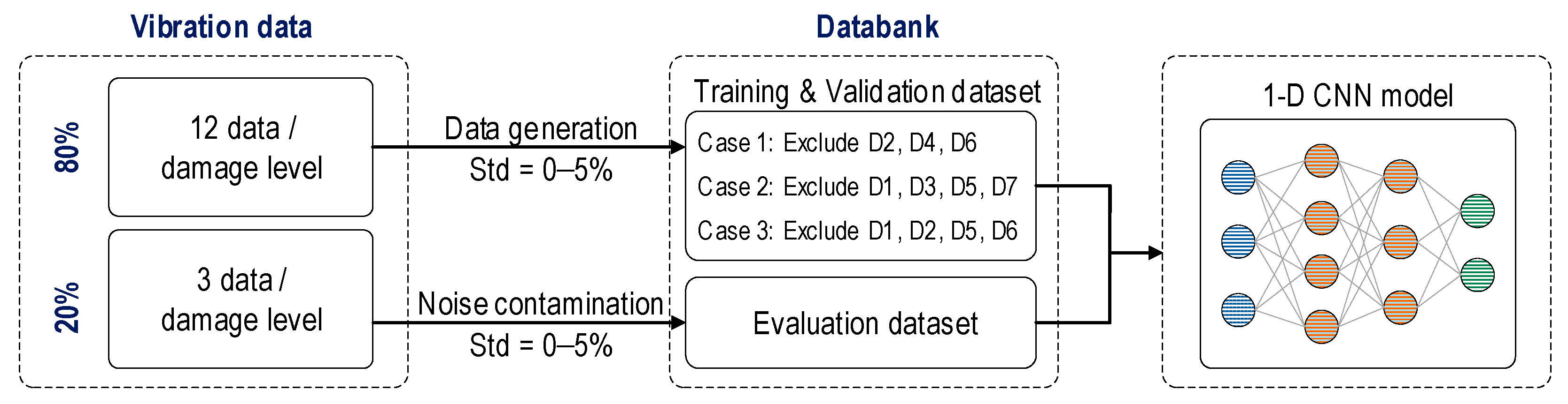
3.4.1. Deep Learning of Noise-Contaminated Databank

Several factors can affect the vibration test, such as noise (including environmental noise and electrical noise from the monitoring devices) and inconsistencies in the excitation source. The data are enriched by obtaining a large number of ensembles to capture as much variation in the excitation source as possible. Despite efforts to control the noise and the magnitude of the vibration source, variations in vibration data are inevitable. Conducting comprehensive experiments that account for all of these variables is challenging and costly. Data augmentation by injecting Gaussian noise into the measured signals is a practical solution for simulating realistic measurement conditions. Introducing noise into the data is also an effective method for enriching the dataset. Several noise levels injected ensure that the CNN model is exposed to a wider range of data during training. It leads to a more robust and general model that can perform on unseen and real-world vibration data.
Figure 5 illustrates the process for configuring the noise-contaminated databank. The vibration data were obtained in 15 ensembles for each foundation damage level. Eighty percent (80%) of the total vibration data was used for training and validation datasets. Data generation used Gaussian noise with standard deviations of 0%, 1%, 2%, 3%, 4%, and 5% of the signal amplitude. The remaining 20% of the total vibration data had noise levels injected ranging from 1% to 16% (in 1% increments) to form the evaluation dataset. This evaluation dataset was used to examine the effect of noise on the accuracy of the 1-D CNN model.

3.4.2. Deep Learning of Partially Untrained Databanks

The foundation of the caisson system sustains various types of damage after extreme events such as storms or tsunamis. For training a CNN model, vibration data can be collected directly from these damaged caissons and labeled according to the severity of the damage. However, a concern is the availability of such data. With variations in shape, location, and severity of foundation damage, each collected sample differs and may not correctly represent feasible damage scenarios. Therefore, it is necessary to train the CNN model by utilizing limited data as well as to recognize unseen damage cases by classifying them into the trained databank of the CNN model. To assess the capability of the 1-D CNN model, certain damage levels were excluded to create partially untrained databanks.
As shown in Figure 6, noise levels ranging from 1% to 5% were added to the 12 ensembles to create the training and validation datasets. Three untrained cases were designed to examine the effect of missing data on the performance of the 1-D CNN. In Case 1, the training and validation set excluded three damage levels: D2, D4, and D6 (from eight damage levels D0–D7), while in Case 2 and Case 3, the training and validation set excluded four damage levels (Case 2: D1, D3, D5, and D7; Case 3: D1, D2, D5, and D6). For the evaluation dataset, the remaining three ensembles were injected with noise levels from 1% to 5% with intervals of 1%.

4. Experiment on a Lab-Scale Caisson-Foundation System

4.1. Vibration Test on a Lab-Scale Caisson System

Figure 7a shows an Oryuk-do caisson-foundation system investigated by Lee et al. [12]. The submerged breakwater system consists of 50 caisson units and has a total length of 1004 m. Each caisson unit is 20 m in width, 20 m in length, and 20.78 m in height. As detailed in Figure 7b, the concrete caisson in the lab-scale experiment was scaled down to 1/20 of the real size, with measurements of 1200 mm in width, 1100 mm in length, and 1300 mm in height. The foundation mound of the lab-scale system is made of a sand layer of 480 mm and an armor gravel layer of 100 mm.
Figure 8 shows the experimental setup for the vibration test on the lab-scale caisson-foundation system. The foundation consisted of a sand mound and gravel armor. The sand mound was precisely dimensioned and compacted to guarantee the stability of the caisson system. The caisson was placed on top of the mound, featuring shear keys to ensure precise alignment and secure interlocking. To further reinforce the structural integrity, a 100 mm layer of gravel was applied on top of the sand mound.
Accelerometers (model PCB 393B04) (i.e., ACC x, ACC y, ACC z) were installed on top of the caisson via steel cubes to measure vibrations along the x, y, and z directions. In this setup, two sensors were placed in the x-direction (labeled as 2x and 3x), one sensor in the y-direction (labeled as 2y), and two sensors in the z-direction (labeled as 1z and 2z).
The data acquisition system comprised a signal conditioner (model 481A, PCB Piezotronics, New York, United States), a terminal block (BNC 2090A), a DAQ card (model 6036E), and a laptop. A steel block suspended from a 1300 mm rope was swung freely from a distance of 400 mm to simulate the impact load on the caisson. The time-history responses were collected in 15 ensembles. The obtained time-history responses were then concatenated according to the previously described methodology.

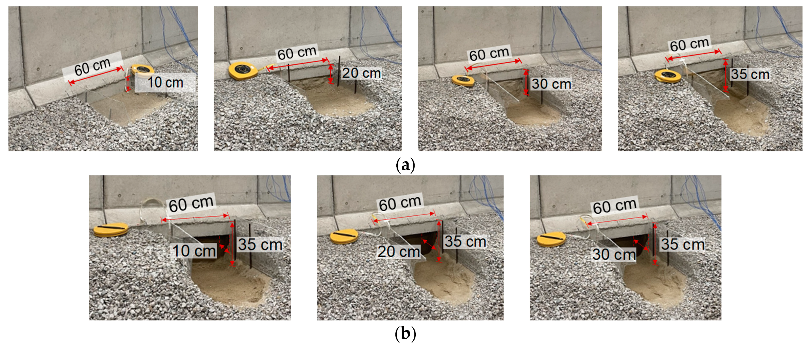
4.2. Foundation-Damage Scenarios

The foundation damage was simulated to mimic a variety of damage scenarios caused by scouring during extreme storm surge events. Figure 9 shows eight levels of foundation damage simulated by sequentially removing various amounts of gravel armor and sand from the foundation mound.
As shown in Figure 9a, the cut-off width was set to 60 cm (i.e., half of the caisson width). Damage 1 to Damage 4 were introduced by removing the depth of the mound up to 10 cm, 20 cm, 30 cm, and 35 cm, respectively. Damage 1 removed 0.37 kN of gravel, which was approximately 2.3% of the armor gravel. Damage 2 removed a total of 0.90 kN material from foundation. It involved 0.46 kN of gravel (about 2.8% of the armor gravel) and 0.44 kN of sand (about 0.7% of the sand mound). Damage 3 resulted in the removal of 0.56 kN gravel (about 3.4% of the armor gravel) and 0.91 kN sand (about 1.5% of the sand mound). Damage 4 removed another 50 mm layer, bringing the total to 0.58 kN of gravel (about 3.6% of the armor gravel) and 1.14 kN of sand (about 1.9% of the sand mound).
As shown in Figure 9b, Damage 5 to Damage 7 expanded the damage to foundation–caisson interface with dug hole depths ranging from 100 mm to 300 mm. This resulted in total extracted sand weights of 1.35 kN, 1.56 kN, and 1.77 kN (about 2.2%, 2.5%, and 2.9% of the sand mound), while the removed gravel remained constant at 0.58 kN. The configuration of the foundation damage scenarios is summarized in Table 2.

4.3. Vibration Data Acquired from Accelerometers

The time-history responses were acquired at a sampling rate of 1.0 kHz. For each impact load, the time-history responses of five sensors (i.e., ACC1z, ACC 2z, ACC 2x, ACC 3x, and ACC 2y) were recorded simultaneously. The observation period was set to 1 s, resulting in 1000 data points per response (90 data points before and 910 data points after the impact load). Comparing the five accelerometers on each caisson, the acceleration magnitude in the z-direction was smaller than in the x- and y-directions. The time-history responses from the five sensors were then concatenated into a single response of 5000 data points. The representative time-history responses of five accelerometer sensors in eight foundation damage levels (D0–D7) are plotted in Figure 10.
The FFD method was used to extract the SVD from the time-history responses. Figure 11 plots the SVD responses calculated simultaneously from all five accelerometers (i.e., 1z, 2z, 2x, 3x, and 2y). The SVD responses were relatively uniform under all foundation damage levels (D0–D7). Three peaks were identified to represent the caisson’s behavior: the first peak frequencies ranged from 25.9 to 27.3 Hz, the second from 183.6 to 186.8 Hz, and the third from 279.8 to 281.2 Hz.

5. Development of 1-D CNN Models

5.1. 1-D CNN Model Using Time-History Response

5.1.1. Databank of Time-History Responses

The concatenated time-history responses were processed with controlled noise contamination to improve the CNN model’s adaptability to real-world conditions. Noise was introduced at 1–10% standard deviation levels across ten iterations. Figure 12 illustrates examples of contaminated responses compared to their original responses.
The time-history responses were used to generate datasets for CNN model development. The responses were acquired in 15 ensembles for each damage level, of which 80% were used for training and validation and 20% reserved for evaluation. A total of 120 responses obtained from eight levels (D0–D7) were divided into 96 responses for training/validation and 24 responses for evaluation. The noise-contamination process generated 4800 responses from the 96 original responses, resulting in a dataset of 4896 responses for training and validation. The evaluation dataset was constructed using the same method to maintain the consistency of the databank structure. The evaluation dataset had 1224 responses, consisting of 24 original responses and 1200 responses generated through noise contamination.
Figure 13 shows the 4896 responses from the foundation damage levels (D0–D7) used for training and validation. Each response consisted of 5000 data points with magnitudes ranging from –0.6 to 0.6. The time-history responses from eight damage levels were labeled accordingly before input into the 1-D CNN model.

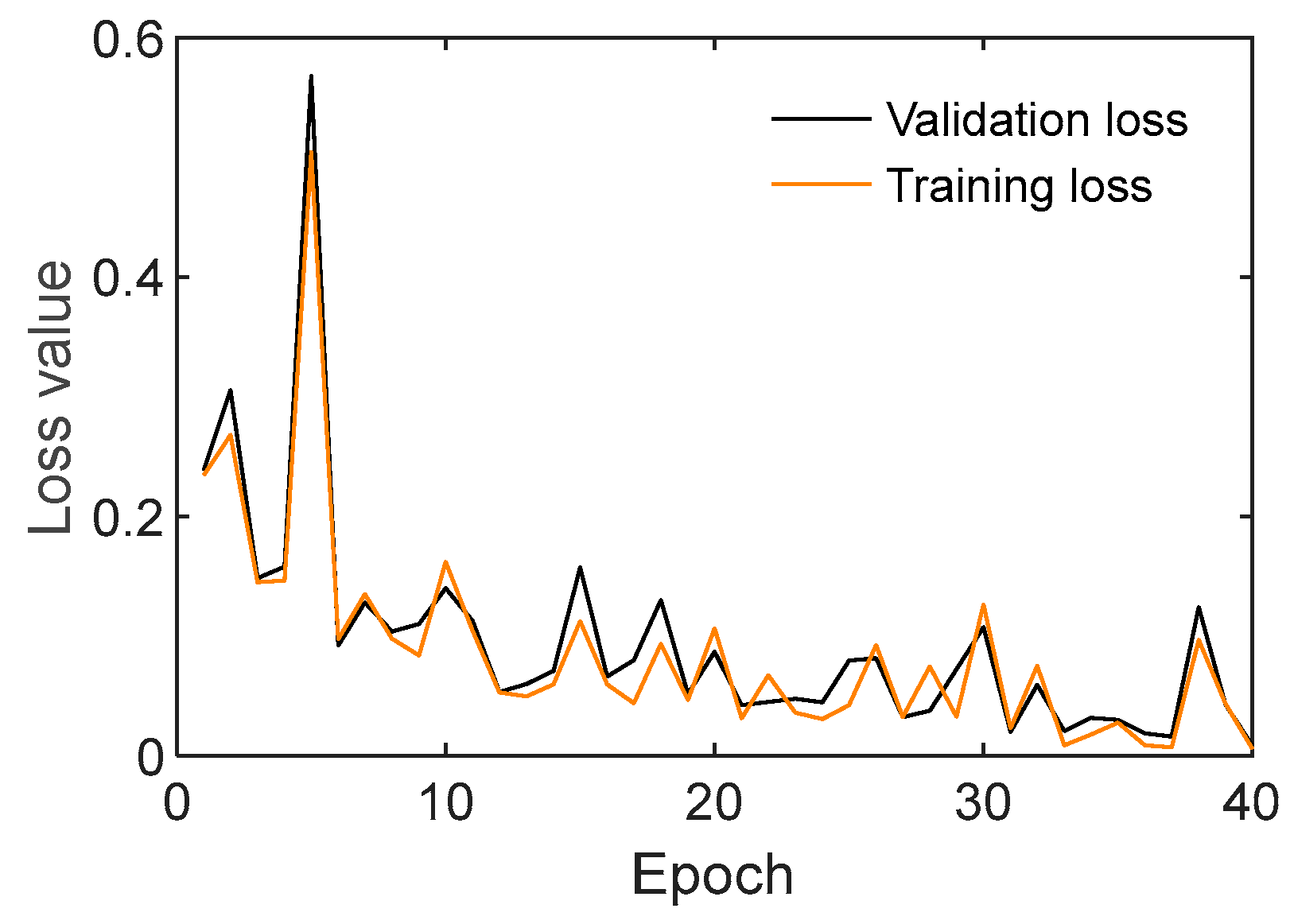
5.1.2. Training Procedures of Time-History Responses

Figure 14 shows the loss values of the CNN model trained by time-history responses. Training loss decreased in the first five iterations and then converged until the end of training. Validation losses sharply decreased in the initial five iterations and maintained stable status until the end at 40th iteration. In general, the training and validation losses performed well and converged after only a few epochs.

5.1.3. Evaluation of 1-D CNN Model Using Time-History Responses

The 1-D CNN model was evaluated using 20% of the time-history responses from the eight damage levels. As shown in Figure 15, confusion matrices were used to quantify the classification performance. The elements on the diagonal positions represent correct classifications (true positives, TP). The off-diagonal elements indicate incorrect classifications (false negatives, FN, and false positives, FP). True positive rate (TPR, so-called ‘recall’) was calculated as TPR = TP/(TP + FN), while false negative rate (FNR) was calculated as FNR = FN/(FN + TP). Precision was calculated as Precision = TP/(TP + FP), and accuracy was calculated as Accuracy = TP/(TP + FP + FN). F1-score was calculated as F1 = (2 × Precision × Recall)/(Precision + Recall).
Figure 15a plots the damage classification results of the CNN model using the time-history databank for a trained noise level of 1%. The red tick (✓) denotes the correct level of inflicted damage. All data were classified correctly except in damage levels D1 (nine misclassifications) and D3 (one misclassifications), resulting in an overall accuracy of 93.75%. Figure 15b plots the damage classification results of the CNN model for a trained noise level of 5%. There were one to six misclassifications in each damage level, and the accuracy of the classification was reduced to 87.50%; nevertheless, the CNN model’s reliability was demonstrated, with the majority of classifications being correct.
Figure 15c shows the damage classification results of the CNN model using time-history databank for an untrained noise level of 6%. Misclassifications appeared in all damage levels except for the intact level (D0). Noticeably, more than half of the data in damage levels D1 and D6 were misclassified. The overall accuracy of classification decreased to 76.88%. For an untrained noise level of 10%, more than half of the data in several damage levels were misclassified, as shown in Figure 15d. The accuracy of the results dropped to 53.12%. Despite this, most data fell in the nearby neighbor classes of the correct ones, suggesting that the CNN model can handle high noise levels with an acceptable error. However, there is a need to develop a technique that can minimize errors and improve the accuracy of the classification.
Figure 16 summarizes the accuracy metrics of the CNN model using time-history databank under the effect of noise. Accuracy, false positive rate (FPR), false negative rate (FNR), and F1-score were chosen to be analyzed (see Figure 16a–d). A better damage classification result was indicated by higher accuracy and F1-score value, and lower FPR and FNR. The accuracy values of the CNN model corresponding to noise levels of 0–5% ranged from 94–87%, followed by a constant decrease until they reached 53% at a noise level of 10%. The FPR value ranged from 4–11% for trained noise levels (0–5%) and abruptly increased to 20% at a noise level of 6%. The FPR continued to rise, reaching 41% at a noise level of 10%. Similarly, the FNR value was below 12.5% for noise levels 0–5% and then significantly increased for noise levels of 6–10%, with a maximum error of 47% at a noise level of 10%. The F1-score remained around 0.92 for trained noise levels 1–5%, then constantly decreased in untrained noise levels until reaching 0.79 at a noise level of 10%.
The CNN model trained by time-history response data demonstrated its feasibility in damage detection and monitoring. It maintained good performance with high noise levels (up to 5%). However, the model showed limitations when confronting untrained noise levels (6–10%).

5.2. 1-D CNN Model Using SVD Responses

5.2.1. Databank of SVD Responses

Figure 17 shows examples of contaminated SVD responses compared to their original ones. The training, validation, and evaluation datasets for the CNN model were generated from 120 SVD responses obtained from eight damage levels (D0–D7), for which 80% of the data (96 responses) were used for training and validation, and 20% of the data (24 responses) were used for evaluation. Noise was introduced at 1–10% standard deviation levels to SVD responses across ten generating iterations. After the noise contamination process, the training and validation datasets consisted of 4896 data, and the evaluation dataset consisted of 1224 data.
Figure 18 visualizes 4896 data points in training and validation datasets for eight foundation damage levels (D0–D7). Each response comprises 5000 data points ranging in magnitude from 0 to 1. These SVD responses were labeled accordingly before input into the 1-D CNN model.

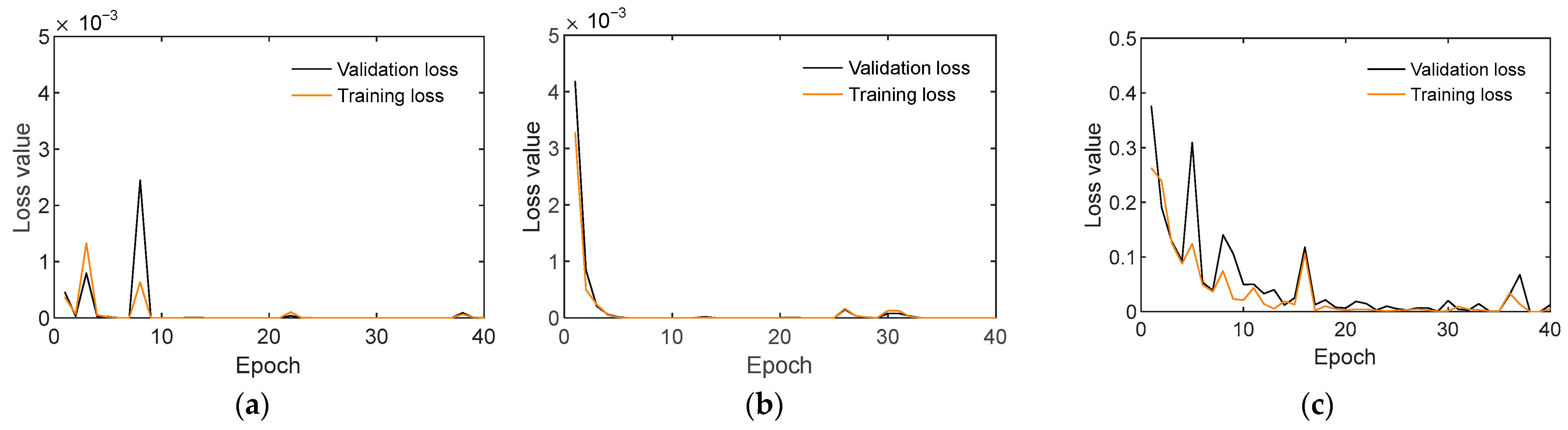
5.2.2. Training Procedures of SVD Responses

Figure 19 shows loss values of the CNN model trained by SVD responses. Both the training and validation losses consistently decreased over 40 iterations and converged to nearly zero by the end of training. The CNN model designed with a compact architecture demonstrated efficient convergence after only a few epochs.

5.2.3. Evaluation of the 1-D CNN Model Using SVD Responses

Figure 20a plots the damage classification results of the CNN model using the SVD databank for the trained noise level of 1%. There were five misclassifications in damage level D3 and two misclassifications in damage level D4. The accuracy of classification reached 95.62%. As the noise level increased up to 5% (Figure 20b), the accuracy decreased to 90%, with one to nine misclassifications in damage levels D1–D4.
Figure 20c shows the damage classification results of the CNN model using the SVD databank for the untrained noise level of 6%. Misclassifications appeared at all damage levels except for the intact level (D0). The overall accuracy of classification was 86.88%. As the noise level increased to 10% (see Figure 20d), the accuracy decreased to 71.25%. There were fewer than five misclassifications out of 20 data for each damage level, except for damage levels D3 and D4. The number of misclassifications was significantly smaller than the model trained using time-history responses at the same noise level.
Figure 21 summarizes the accuracy metrics of the CNN model trained using SVD responses under the effect of noise. Accuracy, false positive rate, false negative rate, and F1-score were analyzed (see Figure 21a–d), and the results were compared to the accuracy metrics of the CNN model trained using time-history responses.
The accuracy of the CNN model trained by SVD responses ranged from 91% to 96% for noise levels 0–5%. It slightly outperformed the CNN model trained using time-history responses, but the difference in accuracy between the two models was not significant. The performance divergence became clearer at higher noise levels (6–10%). At a noise level of 10%, the accuracy of the CNN model trained using SVD responses decreased to 71% compared to 53% using the time-history responses, suggesting that the CNN model trained with SVD responses exhibited improved robustness against untrained noise levels.
For trained noise levels (0–5%), FPR values ranged from 4% to 11% and increased significantly to 20% at a noise level of 6% and continued to rise to 41% at a noise level of 10%. Similarly, FNR values remained below 12.5% for noise levels 0–5%, but increased significantly to a maximum of 47% at noise level 10%.
In Figure 21d, the F1-score of the CNN model trained using SVD responses was above 0.9 for trained noise levels 0–5%. The F1-score rapidly declined for the untrained noise levels and dropped to 0.72 at a noise level of 10%. The F1-score indicated that the performance is not as strong as the CNN model trained using time-history responses.
The p-value of the one-tailed t-test [24] was employed to evaluate the difference in performance of two approaches. A low p-value (typically ≤ 0.05) indicates that the differences in performance are statistically significant. In Figure 21d, the p-value of the F1-score was greater than 0.05, indicating that the performance comparison based on the F1-score was not statistically significant. As shown in Figure 21a–c, the p-values of accuracy, FPR, and FNR were less than 0.05, indicating that using SVD data improved the CNN performance significantly.
In summary, the CNN model trained with SVD responses demonstrated its efficacy in damage detection and monitoring. It maintained good performance even with noise levels up to 5%. This matched the performance of the CNN model trained with time-history responses. However, the model trained with SVD responses demonstrated better performance when dealing with untrained noise levels (6–10%).
The computations were performed on a desktop computer (CPU—Intel Core i7-10700F 2.9 GHz). The training times for the CNN model using time-history and SVD data were 7 and 4 min, respectively. Both approaches demonstrate computational efficiency that is suitable for real-time monitoring applications. With the relatively short training times, models can be quickly updated or retrained when new data are available.

6. Evaluation of 1-D CNN Models for Untrained Damage Cases

6.1. Damage Classification by 1-D CNN Model Using Time-History Responses

Three untrained damage cases were established, as outlined in Table 3. To create partially untrained data scenarios, certain damage levels were excluded from the training and validation datasets. For Case 1, the damage levels D2, D4, and D6 were excluded from among the eight damage levels (D0–D7), resulting in 3060 responses remaining in the training and validation datasets. For Case 2, the training and validation datasets excluded four damage levels (D1, D3, D5, and D7). Case 3 excluded data from damage levels D1, D2, D5, and D6, leaving 2448 responses in the training and validation datasets.
Figure 22 shows the loss values of the CNN models using partially untrained time-history databanks. For all three cases, the training and validation losses decreased sharply in a few initial iterations and converged by the end of the 40 iterations. The training and validation losses demonstrated good performance of all three CNN models.
Figure 23 shows the damage classification results of the CNN model using partially untrained time-history databanks. The red ticks indicate the correct level of the inflicted damage. With untrained cases, the CNN model was limited in accessibility to certain damage levels. When encountering an unseen damage level, the CNN model could not directly classify data to untrained levels. Instead, it was expected to return the classification results in the most similar trained damage levels (the green ticks).
Figure 23a shows the damage classification results for the untrained Case 1. The data in all trained damage levels wasaccurate, with no misclassifications. The untrained damage levels were classified to nearby ones: D2 was classified to D3; D4 was classified to D3 and D5; D6 was classified to D5 and D7. Figure 23b shows the damage classification results for the untrained Case 2. There was no misclassification in the classification results for trained levels (i.e., D0, D2, D4, and D6). The untrained damage levels were classified into nearby ones: data from D1 and D3 were classified as D2; and data from D5 and D7 were classified as D6. Figure 23c shows the untrained Case 3. The distance between trained damage levels increased to two levels when D1, D2, D5, and D6 were neglected. The CNN model maintained its ability to make correct classifications for trained damage levels. The untrained damage levels D1 and D2 were classified as the nearest damage level D3, while untrained damage levels D5 and D6 were classified as the nearest damage level D7.
In practice, only a finite number of damage levels can be provided for model training. The results with partially untrained databank demonstrated the CNN model’s ability to classify unseen damage levels into nearly similar damage levels. This reduced the need to provide many training cases, making the CNN model feasible for real applications in caisson systems.

6.2. Damage Classification by 1-D CNN Models Using SVD Responses

For SVD responses, three partially untrained datasets were generated similarly to time-history responses as shown in Table 3. Figure 24 shows the loss values of the CNN model trained using partially untrained SVD databanks. In both Case 1 and Case 2, the training and validation losses exhibited a sharp decrease in the first ten iterations, followed by convergence to near-zero values by the 40th iteration. For Case 3, the training and validation losses showed a slower initial decline over the first 20 iterations, followed by minor fluctuations until the end of training.
Figure 25 shows the damage classification results of the CNN model with partially untrained SVD databanks. For Case 1 (Figure 25a), all results for trained levels showed no misclassification. The damage levels D2, D4, and D6 were classified to nearby levels D1, D3, and D7, respectively. Case 2 (Figure 25b) demonstrated no misclassification in the results for trained levels (i.e., D0, D2, D4, and D6). The untrained damage levels D1, D3, and D7 were classified into nearby levels D2, D4, and D6, respectively. The untrained damage level D5 was classified into D4 and D6.
In Case 3 (Figure 25c), results for trained levels D0 and D7 showed no misclassification, but 50% of the data for D3 and D4 was misclassified. The untrained damage levels D1 and D2 were classified to the nearest damage level D3; untrained damage level D5 was classified to the nearest damage level D4; and D6 was classified to the nearest damage level D7.

6.3. Discussion on Damage Classification Results

In Figure 26, the damage classification results of CNN models (shown in Figure 23 and Figure 25) are analyzed for untrained Case 1 using the normal probability density function (PDF) [25]. In Figure 26a, the classification results are depicted in blue (based on time-history data) and red (based on SVD data), while the combined results are shown in green. The shaded region represents the range within one standard deviation ( σ ) from the mean value ( μ ) and encompasses 68.8% of the observed values from the central tendency of the prediction.
For the untrained damage D2 in Case 1, the damage classification results (see Figure 23a and Figure 25a) were assessed as shown in the PDF chart in Figure 26a. In the figure, the blue-shaded region indicates damage level D3 based on the time-history data. The red-shaded region indicates damage level D1 based on the SVD data. Combining the two results, the green-shaded region indicates that the damage level was classified to D2.
For the untrained damage D4 in Case 1 (Figure 26b), the blue-shaded region indicated damage levels D4–D5 based on the time-history data, where the mean value leans towards D5. All classification results based on SVD data indicated damage level D3, hence their normal PDF chart is not shown. The combined results in the green-shaded region indicate that the damage level was classified to D4.
For the untrained damage level D6 in Case 1 (Figure 26c), both blue and red-shaded regions indicate damage level D7. Consequently, the green-shaded region for the combined results indicates that the damage level belonged to D7.
In Figure 27, the damage classification results (see Figure 23b and Figure 25b) are analyzed for Case 2 using the PDF chart. For the untrained damage level D1 in Case 2, all results indicated the nearest trained damage level D3. Similar to untrained damage level D7 in Case 2 (Figure 27d), all results indicated the nearest trained damage level D6. The normal PDF chart is not shown for these cases.
For the untrained damage level D3 in Case 2 (Figure 27b), the results based on time-history and SVD data indicated damage levels D2 and D4, respectively. Combining the two results, the green-shaded region indicates that the damage level was classified to D3. For the untrained damage level D5 in Case 2 (see Figure 27c), all three shaded regions indicate that the damage level fell between D5 and D6, with the mean value leaning towards D6.
In Figure 28, the damage classification results (see Figure 23c and Figure 25c) are analyzed for Case 3. For the untrained damage levels D1 and D2 in Case 3 (see Figure 28a,b), almost all results based on time-history and SVD data indicated the nearest trained damage level D3. The green-shade region indicates that the damage belonged to D3.
Figure 28c shows the probability assessment for the untrained damage level D5 in Case 3. In the figure, the blue-shaded region indicates the damage level D7 based on time-history data. The red-shaded region indicates the damage level D4 based on SVD data. Combining the two results, the green-shaded region indicates that the damage level belongs to D5 and D6, with the mean value leaning towards D5. For the untrained damage level D6 in Case 3 (see Figure 28d), all three shaded regions indicate that the damage level belonged to D7.
This visualization highlights the CNN models’ performance with partially untrained data and demonstrates their capability to classify untrained damage levels into the most similar trained levels. Additionally, combining results from two approaches using time-history and SVD data could strengthen classification results and provide additional insights for investigators.
Figure 29 compares the accuracy of CNN models trained using time-history and SVD data under three untrained cases. All CNN models achieved high accuracy. For Case 1 and Case 2, the CNN models trained using time-history responses achieved accuracies of 99.6% and 99.9%, respectively. Meanwhile, the CNN models trained using SVD responses had an accuracy of 100% for both cases. For Case 3, the CNN model trained using time-history data maintained high accuracy at 99.5%. However, the accuracy of the CNN model trained using SVD data fell to 86.9%. Note that the misclassification mainly came from the trained damage levels (i.e., D3 and D4). This comparison reveals that each approach adapted to particular situations. Therefore, using both approaches and integrating their results could provide better insights and enhance overall classification accuracy.

7. Conclusions

This study introduced a novel approach that applies CNN deep learning to both time-history and SVD responses for identifying damage in submerged structure-foundation systems. Firstly, various foundation damage levels were simulated in a lab-scale caisson-foundation system, and corresponding time-history responses were recorded using accelerometers. Secondly, the 1-D CNN deep learning model was trained using time-history responses. Thirdly, the 1-D CNN model was trained using the SVD responses derived from time-history responses. Finally, the trained CNN models were implemented to evaluate the damage within the system’s foundation under noise contamination and partially untrained data.
Four main conclusions of the study are summarized as follows:
(1)
The CNN deep learning model trained using time-history and SVD responses successfully classified the foundation damage of the caisson system.
(2)
The t-test evaluation on performance metrics indicated that the CNN model trained using SVD responses outperformed the CNN model trained using time-history responses, particularly when dealing with untrained noise levels. The findings underscore the effectiveness of using additional vibration features such as SVD data.
(3)
The performance of the CNN model was maintained with partially untrained cases. The CNN models trained using time-history and SVD responses successfully classified the untrained damage levels as the most similar trained damage levels. This outcome demonstrates the robustness and potential effectiveness of the CNN model under in situ conditions.
(4)
Integrating the time-history and SVD responses strengthened the damage classification results and provided additional insights for investigators.
The proposed approach can be directly integrated into existing monitoring systems as a post-processing and decision-making phase. The CNN deep learning technique requires no additional hardware and only a one-time setup, with the ability to be automatically updated as new data become available. By reducing reliance on manual decision-making, this approach mitigates risks associated with human error and offers long-term benefits by saving expert labor costs. By collaborating with industrial partners, vibration data for training can be collected directly from in situ damaged caissons. The CNN model is continuously updated with variations in the shape, location, and severity of foundation damage. The ongoing refinement and expansion of the dataset enhances the reliability of the CNN model, improving its accuracy and robustness in real-world conditions.
Despite the effectiveness of the developed method for damage detection and monitoring, some aspects need to be resolved. Firstly, the feasibility of the method was proven with experiments on a lab-scaled caisson system. It now needs to be verified with the in situ caisson-foundation systems. Secondly, future investigations should consider different types of noise and the influence of environmental factors. Several other data augmentation techniques such as shifting, amplitude scaling, and window slicing could be applied besides Gaussian noise contamination. Thirdly, the verification of the method should be extended to other machine learning models. Although integrating various vibration features has proven effective for the CNN model, further evaluation is necessary to assess its compatibility with alternative machine learning models. Finally, the investigation showed the dependence of CNN models on the availability of vibration data (i.e., time-history and SVD responses). For real caisson systems, simulating damage to submerged foundations is challenging. Additional research on generating training data through indirect methods such as numerical models and pseudo-damage simulation is needed.

Author Contributions

Conceptualization, J.-T.K. and N.-L.P.; methodology, analysis, writing—original draft, N.-L.P.; data recording, N.-L.P. and Q.-B.T.; investigation and data curation, N.-L.P.; writing—review and editing, J.-T.K.; supervision, J.-T.K. All authors have read and agreed to the published version of the manuscript.

Funding

This work was supported by the Basic Science Research Program through the National Research Foundation of Korea: 2022R1A2C10038891361782064340103.

Institutional Review Board Statement

Not applicable.

Informed Consent Statement

Not applicable.

Data Availability Statement

Data available on reasonable request from the corresponding author.

Conflicts of Interest

The authors declare no conflicts of interest.

References

  1. Brunn, P. Port structures, wharves, quays, terminals, and mooring devices. J. Coast. Res. 2005, SI, 139–158. [Google Scholar]
  2. Matsui, T.; Oda, K. Foundation damage of structures. Soils Found. 1996, 36, 189–200. [Google Scholar] [CrossRef] [PubMed]
  3. Oumeraci, H.; Kortenhaus, A. Analysis of the dynamic response of caisson breakwaters. Coast. Eng. 1994, 22, 159–183. [Google Scholar] [CrossRef]
  4. Yu, C. Numerical simulation of pounding damage to caisson under storm surge. E3S Web Conf. 2018, 38, 03046. [Google Scholar] [CrossRef]
  5. Catbas, F.N.; Ciloglu, S.K.; Hasancebi, O.; Grimmelsman, K.; Aktan, A.E. Limitations in structural identification of large constructed structures. J. Struct. Eng. 2007, 133, 1051–1066. [Google Scholar] [CrossRef]
  6. Ho, D.D.; Kim, J.T.; Stubbs, N.; Park, W.S. Prestress-force estimation in PSC girder using modal parameters and system identification. Adv. Struct. Eng. 2012, 15, 997–1012. [Google Scholar] [CrossRef]
  7. Li, H.N.; Yi, T.H.; Ren, L.; Li, D.S.; Huo, L.S. Reviews on innovations and applications in structural health monitoring for infrastructures. Struct. Monit. Maint. 2014, 1, 1. [Google Scholar] [CrossRef]
  8. Lee, S.Y.; Nguyen, K.D.; Huynh, T.C.; Kim, J.T.; Yi, J.H.; Han, S.H. Vibration-based damage monitoring of harbor caisson structure with damaged foundation-structure interface. Smart Struct. Syst. 2012, 10, 517–546. [Google Scholar] [CrossRef]
  9. Huynh, T.C.; Lee, S.Y.; Kim, J.T.; Park, W.S.; Han, S.H. Simplified planar model for damage estimation of interlocked caisson system. Smart Struct. Syst. 2013, 12, 441–463. [Google Scholar] [CrossRef]
  10. Huynh, T.C.; Lee, S.Y.; Dang, N.L.; Kim, J.T. Vibration-based structural identification of caisson-foundation system via in situ measurement and simplified model. Struct. Control Health Monit. 2019, 26, e2315. [Google Scholar] [CrossRef]
  11. Lee, S.Y.; Huynh, T.C.; Kim, J.T. A practical scheme of vibration monitoring and modal analysis for caisson breakwater. Coast. Eng. 2018, 137, 103–119. [Google Scholar] [CrossRef]
  12. Lee, S.Y.; Huynh, T.C.; Dang, N.L.; Kim, J.T. Vibration characteristics of caisson breakwater for various waves, sea levels, and foundations. Smart Struct. Syst. 2019, 24, 525–539. [Google Scholar]
  13. Pham, N.L.; Ta, Q.B.; Kim, J.T. Pseudo-Damage Simulation and CNN Deep Learning for Damage Identification of Submerged Structure-Foundation System. Struct. Health Monit. 2024; under review. [Google Scholar]
  14. Teng, S.; Chen, G.; Yan, Z.; Cheng, L.; Bassir, D. Vibration-based structural damage detection using 1-D convolutional neural network and transfer learning. Struct. Health Monit. 2023, 22, 2888–2909. [Google Scholar] [CrossRef]
  15. Huang, J.; Yin, X.; Kaewunruen, S. Quantification of dynamic track stiffness using machine learning. IEEE Access 2022, 10, 78747–78753. [Google Scholar] [CrossRef]
  16. Li, F.; Wang, L.; Wang, D.; Wu, J.; Zhao, H. An adaptive multiscale fully convolutional network for bearing fault diagnosis under noisy environments. Measurement 2023, 216, 112993. [Google Scholar] [CrossRef]
  17. Ming, G.; Guanying, D.; Jihua, Y. Dynamic studies on caisson-type breakwaters. Coast. Eng. 1988, 2469–2478. [Google Scholar] [CrossRef]
  18. Khodabandehlou, H.; Pekcan, G.; Fadali, M.S. Vibration-based structural condition assessment using convolution neural networks. Struct. Control Health Monit. 2019, 26, e2308. [Google Scholar] [CrossRef]
  19. Lin, Y.Z.; Nie, Z.H.; Ma, H.W. Structural damage detection with automatic feature-extraction through deep learning. Comput.-Aided Civ. Infrastruct. Eng. 2017, 32, 1025–1046. [Google Scholar] [CrossRef]
  20. Brincker, R.; Zhang, L.; Andersen, P. Modal identification of output-only systems using frequency domain decomposition. Smart Mater. Struct. 2001, 10, 441. [Google Scholar] [CrossRef]
  21. Yi, J.H.; Yun, C.B. Comparative study on modal identification methods using output-only information. Struct. Eng. Mech. Int. J. 2004, 17, 445–466. [Google Scholar] [CrossRef]
  22. Ewins, D.J. Modal Testing: Theory, Practice and Application; John Wiley & Sons: Hoboken, NJ, USA, 2009. [Google Scholar]
  23. Sarawgi, Y.; Somani, S.; Chhabra, A.; Sangwan, D. Nonparametric vibration-based damage detection technique for structural health monitoring using 1D CNN. In Proceedings of the Computer Vision and Image Processing: 4th International Conference, Jaipur, India, 27–29 September 2019. [Google Scholar]
  24. Pearson, K. Contributions to the mathematical theory of evolution. Philos. Trans. R. Soc. London 1894, 185, 71–110. [Google Scholar]
  25. Loeve, M.M. Probability Theory, 2nd ed.; Springer: New York, NY, USA, 1960. [Google Scholar]
Figure 1. Scheme of CNN deep learning model for a caisson-foundation system using vibration data.
Applsci 14 07508 g001
Figure 2. Vibration monitoring setup on a submerged caisson-foundation system.
Applsci 14 07508 g002
Figure 3. Vibration measurements for a caisson-foundation system: (a) accelerometer setup and impact load; (b) Concatenated time-history response.
Applsci 14 07508 g003
Figure 4. Schematic of a 1-D CNN classification model: (a) 1-D CNN architecture; (b) data preparation and training procedures.
Applsci 14 07508 g004
Figure 5. Configuration of the noise-contaminated databank.
Applsci 14 07508 g005
Figure 6. Configuration for a partially untrained databank.
Applsci 14 07508 g006
Figure 7. Parameters of the caisson breakwater system: (a) Oryuk-do caisson breakwater system [19]; (b) lab-scale caisson-foundation model [13].
Applsci 14 07508 g007
Figure 8. Experimental setup of the lab-scale caisson-foundation system.
Applsci 14 07508 g008
Figure 9. Foundation damage scenarios: (a) Damage 1–Damage 4; (b) Damage 5–Damage 7.
Applsci 14 07508 g009
Figure 10. Time-history responses of five accelerometer sensors.
Applsci 14 07508 g010
Figure 11. SVD responses of five accelerometer sensors.
Applsci 14 07508 g011
Figure 12. Illustration of noise contamination to time-history responses: (a) 5% noise; (b) 10% noise.
Applsci 14 07508 g012
Figure 13. Visualization of time-history responses for training and evaluation of CNN model.
Applsci 14 07508 g013
Figure 14. Loss values of the 1-D CNN model trained by time-history responses.
Applsci 14 07508 g014
Figure 15. Damage classification results of the 1-D CNN model using the time-history databank: (a) trained 1% noise; (b) trained 5% noise; (c) untrained 6% noise; (d) untrained 10% noise. The red tick (✓) denotes the correct level of inflicted damage.
Applsci 14 07508 g015
Figure 16. Noise effect on the 1-D CNN model trained by time-history data: (a) accuracy; (b) false positive rate; (c) false negative rate; (d) F1-score.
Applsci 14 07508 g016
Figure 17. Illustration of noise contamination to SVD responses: (a) 5% noise; (b) 10% noise.
Applsci 14 07508 g017
Figure 18. Visualization of SVD responses for training and evaluation of the CNN model.
Applsci 14 07508 g018
Figure 19. Loss values of the 1-D CNN model trained by SVD responses.
Applsci 14 07508 g019
Figure 20. Damage classification results of the 1-D CNN model using SVD databank: (a) trained 1% noise; (b) trained 5% noise; (c) untrained 6% noise; (d) untrained 10% noise. The red tick (✓) denotes the correct level of inflicted damage.
Applsci 14 07508 g020
Figure 21. Noise effect on the 1-D CNN model trained using SVD responses compared to the model trained using time-history responses (grey lines): (a) accuracy; (b) false positive rate; (c) false negative rate; (d) F1-score.
Applsci 14 07508 g021
Figure 22. Loss values of the 1-D CNN model using partially untrained time-history databanks: (a) Case 1; (b) Case 2; (c) Case 3.
Applsci 14 07508 g022
Figure 23. Damage classification results of the 1-D CNN model using partially untrained time-history databank: (a) Case 1; (b) Case 2; (c) Case 3. The red ticks indicate the correct level of the inflicted damage. When the CNN model could not directly classify data to untrained levels, it returned the classification results in the most similar trained damage levels (green ticks).
Applsci 14 07508 g023
Figure 24. Loss values of the 1-D CNN model using partially untrained SVD databanks: (a) Case 1; (b) Case 2; (c) Case 3.
Applsci 14 07508 g024
Figure 25. Damage classification results of the 1-D CNN model using partially untrained SVD databanks: (a) Case 1; (b) Case 2; (c) Case 3. The red ticks indicate the correct level of the inflicted damage. When the CNN model could not directly classify data to untrained levels, it returned the classification results in the most similar trained damage levels (green ticks).
Applsci 14 07508 g025
Figure 26. Probability assessment of damage classification results: Case 1: (a) untrained D2; (b) untrained D4; (c) untrained D6. The blue-shaded region shows results based on time-history data, the red-shaded region shows results based on SVD data, and the green-shaded region shows combined results.
Applsci 14 07508 g026
Figure 27. Probability assessment of damage classification results: Case 2: (a) untrained D1; (b) untrained D3; (c) untrained D5; (d) untrained D7. The blue-shaded region shows results based on time-history data, the red-shaded region shows results based on SVD data, and the green-shaded region shows combined results.
Applsci 14 07508 g027
Figure 28. Probability assessment of damage classification results: Case 3: (a) untrained D1; (b) untrained D2; (c) untrained D5; (d) untrained D6. The blue-shaded region shows results based on time-history data, the red-shaded region shows results based on SVD data, and the green-shaded region shows combined results.
Applsci 14 07508 g028
Figure 29. Accuracy of CNN models with untrained cases.
Applsci 14 07508 g029
Table 1. Specification of 1-D CNN layers.
No.TypeDepthFilterStrideNo.TypeDepthFilterStride
1Conv161 × 418ReLU---
2ReLU---9Maxpool3-1 × 22
3Maxpool1-1 × 2210Flatten
4Conv241 × 4111Fc148--
5ReLU---12Fc216--
6Maxpool2-1 × 2213Fc34--
7Conv351 × 8114Classification---
Table 2. Configuration of foundation damage scenarios.
CaseGravel Removed
(% of Gravel Armor)
Sand Removed
(% of Sand Mound)
Descriptions
D0--Undamaged intact state
D10.37 kN (2.3%)-Damage in front slope
D20.46 kN (2.8%)0.44 kN (0.7%)
D30.56 kN (3.4%)0.91 kN (1.5%)
D40.58 kN (3.6%)1.14 kN (1.9%)
D50.58 kN (3.6%)1.35 kN (2.2%)Damage expanded to foundation–caisson interface
D60.58 kN (3.6%)1.56 kN (2.5%)
D70.58 kN (3.6%)1.77 kN (2.9%)
Table 3. Untrained damage cases for evaluating the 1-D CNN model.
CaseScenarioData Type
Training & Validation DatasetsEvaluation Dataset
1Excluding damage levels D2, D4, and D630601224
2Excluding damage levels D1, D3, D5, and D72448
3Excluding damage levels D1, D2, D5, and D62448
Disclaimer/Publisher’s Note: The statements, opinions and data contained in all publications are solely those of the individual author(s) and contributor(s) and not of MDPI and/or the editor(s). MDPI and/or the editor(s) disclaim responsibility for any injury to people or property resulting from any ideas, methods, instructions or products referred to in the content.

