Abstract
The phenomenon of peripheral rock instability is more common in crushed bedrock roadways, and the fundamental reason for this lies in the significantly different characteristics of its peripheral rock stress field. Taking the newly dug belt inclined shaft of PingDingShan TianAn Coal Co., Ltd. No. 6 Mine as the engineering background, a mechanical model of a broken perimeter rock roadway was established by using classical rock mechanics theory. Stress distribution around the roadway of the broken perimeter rock medium was systematically analyzed, and radial and tangential stress formulas of the broken perimeter rock were deduced. Through the formula calculation, it was deduced that there was a stress drop in the intact surrounding rock outside the disturbed zone, and the radial stress of the intact surrounding rock in its deep part was relatively increased, while the tangential stress was relatively decreased. The existence of crushed surrounding rock increased the minimum principal stress and decreased the maximum principal stress of the unfractured surrounding rock, which proves that a well-maintained disturbed zone can play a lining role. Thus, a “U-shaped steel + inverted arch + bottom arch linkage beam + floor bolt compensation” support program was proposed. This joint support program easily forms a closed support structure, which is more effective in controlling the deformation of tunnel perimeter rock. The support structure can effectively resist the deformation of the surrounding rock and enhance bottom drum resistance. Through numerical simulation, it was concluded that the horizontal displacement of the two gangs was reduced by 70%, and the displacement of the top and bottom plates was reduced by 77% after optimization of the support, which effectively controlled the stability of the broken surrounding rock.
1. Introduction
With the innovation of support technology and the improvement of coal mine mechanization, construction technology used for refuge chambers in large cross-section roadways in coal mines is also constantly developing. In recent years, many mines in China have set up a large number of large-section refuge chambers due to the needs of production. However, due to high stress, the complex characteristics of the surrounding rock, and the influence of mining activities, it is extremely difficult to support large-section refuge chambers in fractured surrounding rock; therefore, the phenomenon of the destabilization of the surrounding rock around large-section refuge chambers in fractured surrounding rock is very common in coal mines.
The broken zone of roadway surrounding rock is the main factor leading to the deformation of roadway surrounding rock. When the stability of the roadway is critical, the deep roadway under the rupture state is more severely affected by the disturbance stress and even leads to the overall instability of the surrounding rock structure of the roadway [1]. Therefore, the stability control of deep broken surrounding rock in roadways has attracted the attention of some scholars. For example, Wang Weijun et al. studied the deformation characteristics of fractured perimeter rock under high stress in deep wells and produced a destabilization mechanism, which led to the proposal of “high-resistance pressure and high-intensity support” technology [2]. Meng Qingbin et al. used the characteristic curve method to summarize and provide classical support characteristics and support structure equations, as well as analysis of U-shaped steel support row spacing size and its support pressure provided by a proportional relationship in order for the U-shaped steel support structure parameters to provide effective help [3]. Li Yingjie et al. carried out similar material simulation test research on the damage law of broken and soft rock tunnels and concluded that the damage of this type of perimeter rock tunnel is shear failure from the arch waist first, which then extends to the arch top, and the perimeter rock of the arch top undergoes tensile change to form arch-shaped cracks [4]. Zhao Chengxing et al. adopted the concept of controlling the surrounding rock with two carriers of different sizes and put forward the joint support program of “concrete jetting + grouting bolt/anchor cable + ordinary anchor/anchor cable”, which plays a key role in maintaining the long-term stability of roadways, and it also serves as a reference for the support of roadways in soft rock in the deep part of the country [5]. Meng Bo et al. explored the self-stabilizing and re-bearing instability mechanism of a broken rock anchorage structure through experiments conducted on the broken rock anchorage structure under different preloads, and they concluded that the anchorage structure under a high preload can cause the broken surrounding rock to have more stable self-stabilizing bearing [6]. Feng Guorui and Ma Jingkai established an intrinsic model and an intrinsic equation of bearing damage for crushed perimeter rock with solid grouting, and they explored the dynamic damage evolution law of solid grouting [7]. Anagnostou pointed out that the destructive deformation of weak crushed perimeter rock shows rheological behavior and thought that no big deformation damage is produced in the early stage of excavation but that the crushed perimeter rock would be expanded by creep, and the tunnel would have a big bottom bulge a few years later [8]. Zuo Jianping et al. proposed the mechanical theory of equal-strength support for deep coal mine roadways by analyzing and summarizing the development history of deep roadway support methods domestically and abroad [9]. Luan Bo et al. used numerical simulation and theoretical analysis to derive the development law of a plastic zone of non-equal pressure in a coal roadway under broken surrounding rock, and they proposed the joint support of anchor + net + rope + spray [10]. SHEMYAKIN E I et al. conducted an in-depth study on the mechanisms and conditions of rock fragmentation [11,12,13].
In a large cross-section roadway of broken surrounding rock, anchor rods and anchor cable support are more researched [14,15]. Compared with anchor rods, anchor cable support, and other active support, U-shaped steel support has high tensile strength and compressive strength, a simple structure, and strong support capacity, and it is easy to install and not easy to deform; it is more widely used [16]. In engineering applications, it is used in wall-filling technology for fully closed stents, although the bearing capacity of U-shaped steel support can be greatly improved [17,18,19]. However, the bearing capacity of U-shaped steel support is restricted by different load conditions, support structure, and other conditions. If only relying on its passive support, the self-bearing capacity of deep complete surrounding rock is difficult to manage, and it will still cause the support to be destroyed.
In summary, research on the rock characteristics of broken surrounding rock is more in-depth [20,21,22,23]. The deformation mechanism [24,25], characteristics of broken surrounding rock [26,27], and support theory for large-section broken surrounding rock roadways [28,29] are also constantly discussed. However, for broken zones formed after years of roadway excavation, different characteristics of the stress field in a roadway’s surrounding rock are presented. Therefore, with PingDingShan TianAn Coal Co., Ltd. No. 6 Mine’s new digging belt inclined shaft (North Xinxin Street, Xinhua District, Pingdingshan, China) as the engineering background, and through mechanical analysis, numerical simulation experiments, on-site monitoring, and other methods to study and analyze the deformation and damage in the large cross-section of a roadway’s broken peripheral rock, this paper puts forward the “U-beam + anti-bottom arch + bottom arch interlocking beams + bottom plate anchor compensation” joint support program, which provides a good solution for the control of broken peripheral rock. At the same time, it also provides a new support scheme for the broken surrounding rock of the roadway.
2. Stress Analysis of Broken Perimeter Rock Roadway
When the strength of the surrounding rock of a roadway is low, the surrounding rock of the roadway will be likely to form a fracture zone layer. If the surrounding rock damage is in a brittle form, the bearing capacity of the perimeter rock will decrease significantly; i.e., there is a large stress drop.
The residual strength of the fractured enclosing rock controls the stress distribution of the fractured enclosing rock in the roadway, while the radial stress is continuous; i.e., the radial stress in the fractured zone is equal to the radial stress in the intact enclosing rock. The stress drop in Equation (1) leads to the stress drop in Equation (2) for brittle rupture formation.
—Stress drop; —initial stress; —Termination stress
In the equation
- —Stress drop
- —Radial stress
- —Angle of internal friction of intact enclosing rock
- —Angle of internal friction of the crushing enclosure
- —Uniaxial compressive strength of intact surrounding rock
- —Uniaxial compressive strength of crushed perimeter rock
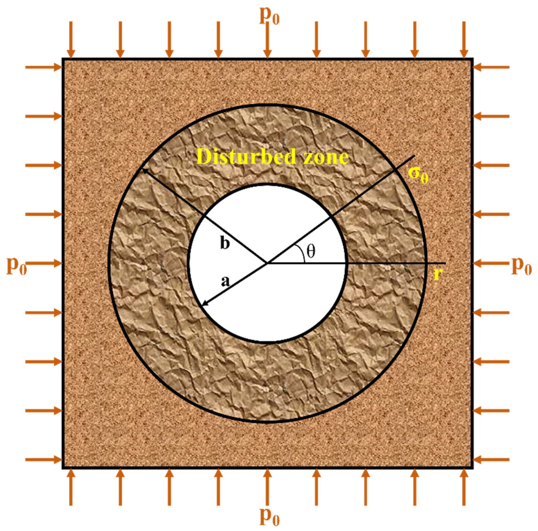
The crushing of the surrounding rock of a roadway changes the mechanical properties of the rock, and its stress distribution is shown in a mechanical model in Figure 1.
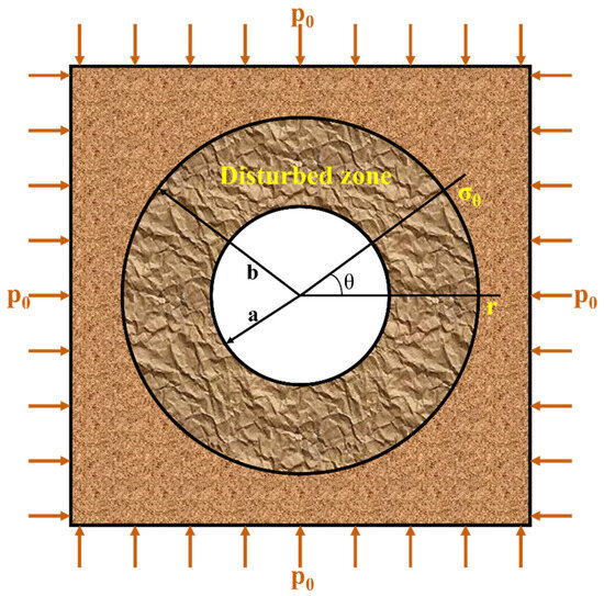
Figure 1.
Mechanical model of a roadway.
Its hydrostatic equilibrium equation is
The residual strength limit equilibrium equation is known to be
Substituting Equation (4) for Equation (3) yields
Integrating Equation (5) yields
Then, its tangential stress is
If the surrounding rock is more fractured, cohesion C0 = 0, and the radial and tangential stresses of the fractured surrounding rock become
From Equation (8), the stress of the crushed surrounding rock is most closely related to the residual strength of the surrounding rock. After many years of excavation of the roadway, the cohesion of the broken surrounding rock still has the stability of the broken surrounding rock. The stability of the roadway is maintained not only by the friction resistance between the broken rock blocks but also by the residual strength and cohesion of the broken surrounding rock, which are the main factors. Therefore, when the inclined well of PingDingShan TianAn Coal Co., Ltd. No. 6 Mine crosses the mining area after many years of excavation, the residual strength and cohesion of the broken rock mass still exist. When digging an inclined well, as long as it is supported in time, even if the support force is not large, the lateral stress of the unbroken rock mass can be increased, thus inhibiting expansion of the plastic area and thus providing a guarantee for the successful passage of the inclined well through the mining area.
The intact surrounding rock outside the fracture zone is in an elastic state, and its stress state satisfies the stress balance equation. According to the boundary conditions outside the disturbed zone, the following equation can be obtained:
From Equations (6) and (9) and the boundary conditions within the fragmentation zone, the following equations are derived:
Equation (10) can be substituted for Equation (9) to find the stress distribution in the intact surrounding rock outside the broken surrounding rock.
The stress of the elastic stress state of the surrounding rock in the roadway is calculated by using Formula (11) and Formula (12), respectively. The stress drop can be obtained (13).
From Equation (13), the radial stress of the crushed surrounding rock channel is larger than that of the deep intact surrounding rock channel, while its tangential stress is exactly the opposite. From this, the existence of crushed perimeter rock increases the minimum principal stress and reduces the maximum principal stress of the deep intact perimeter rock, and if the crushed perimeter rock can be maintained well without a second disturbance, the disturbed zone can play the role of lining. This can be a good explanation for the obvious perimeter rock damage at the beginning of the tunnel excavation, but the perimeter rock damage will not always occur, and the perimeter rock can be a self-stabilizing phenomenon. This phenomenon can be called the “loose self-stabilizing” stage.
3. Mechanisms of “Rock–Support” Interaction
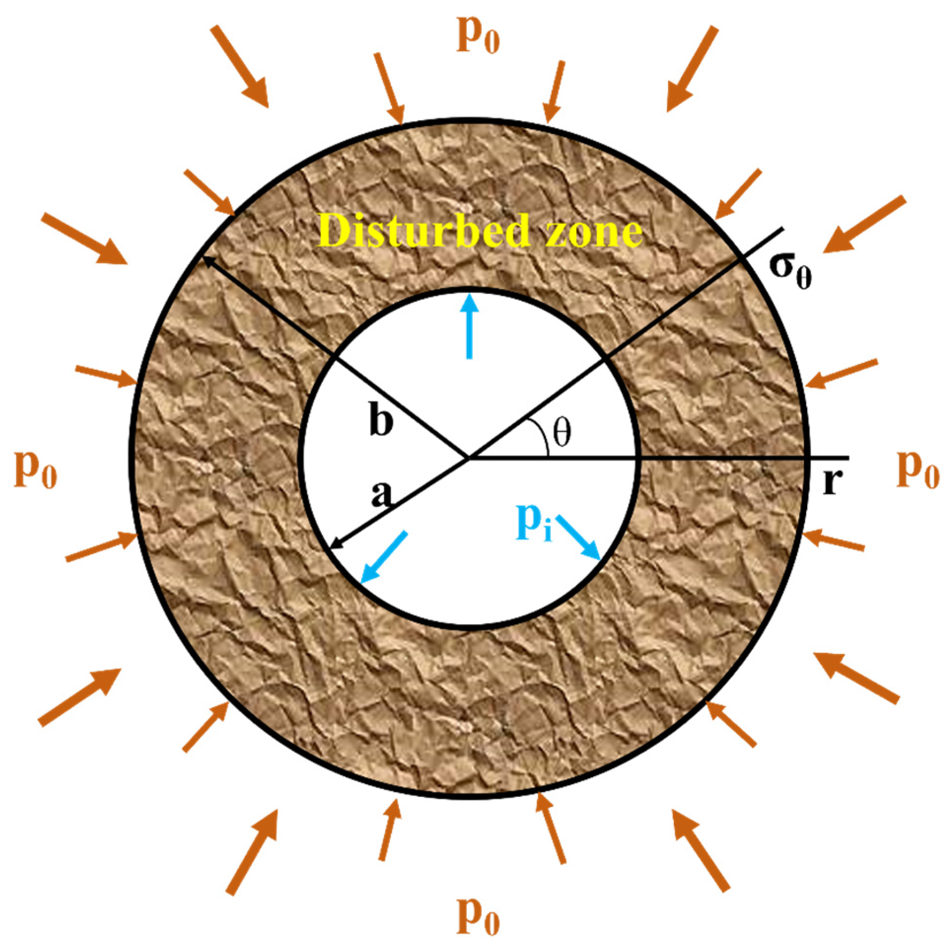
To analyze the interaction mechanism of “surrounding rock–support” in the broken surrounding rock of a roadway, this paper applies the elasticity theory of thick-walled pipe for analysis and research. As shown in Figure 2, the radius of the roadway is a, the radius of the broken perimeter rock is b, the roadway support resistance is pi, the original rock stress is hydrostatic pressure state, and the pressure of the surrounding rock is p0.

Figure 2.
Mechanical model of “surrounding rock–support’’ in the broken surrounding rock of a roadway.
According to the theory of thick-walled tube [30] and Lami’s theorem [31], the stress distribution in the surrounding rock in the elastic zone can be shown as follows:
From the equality of radial stresses at the junction of the elastic zone and the zone of influence of the crushed enclosing rock, it follows that,
Equations (6) and (10) are substituted for Equation (16) to obtain Equation (17); if the radius of the zone of influence of the fractured enclosure is R, Equation (17) can be converted to Equation (18).
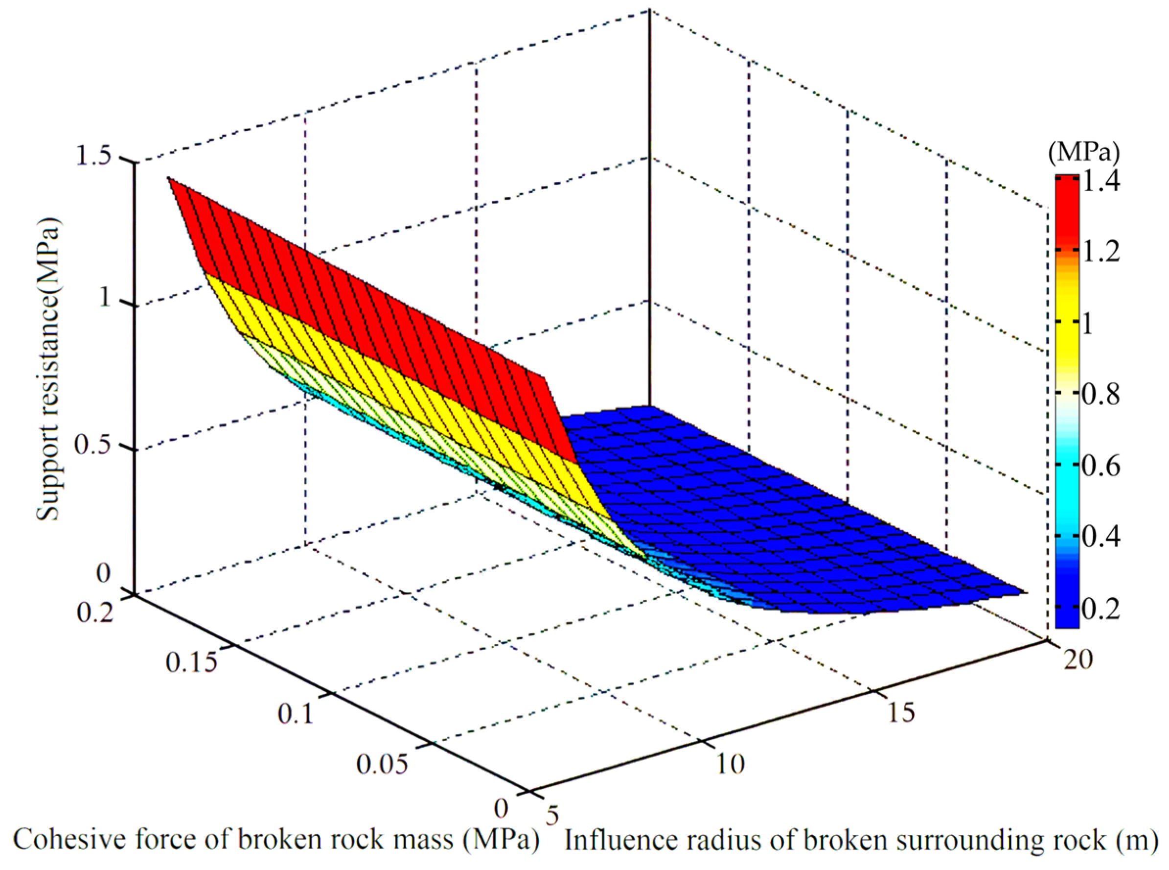
Using Matlab software (Matlab 2014a) to analyze Equation (18) yields Figure 3.

Figure 3.
Relationship between support force, surrounding rock pressure, and influence radius of broken surrounding rock.
From Figure 3, the support force of the broken perimeter rock roadway is inversely proportional to the radius of the broken perimeter rock influence area; with the increase in broken influence area, part of the deformation energy is released, and the pressure of perimeter rock acting on the support becomes smaller. No matter how big the radius of influence of the broken perimeter rock is, the support resistance will not be lower than a certain value; even if the radius of influence of the broken perimeter rock is 0, the support resistance will also be very small. The support force of the broken perimeter rock tunnel is directly proportional to the residual cohesion of the broken rock body, and with the increase in residual cohesion, the greater the support resistance becomes.
4. Support Program Design
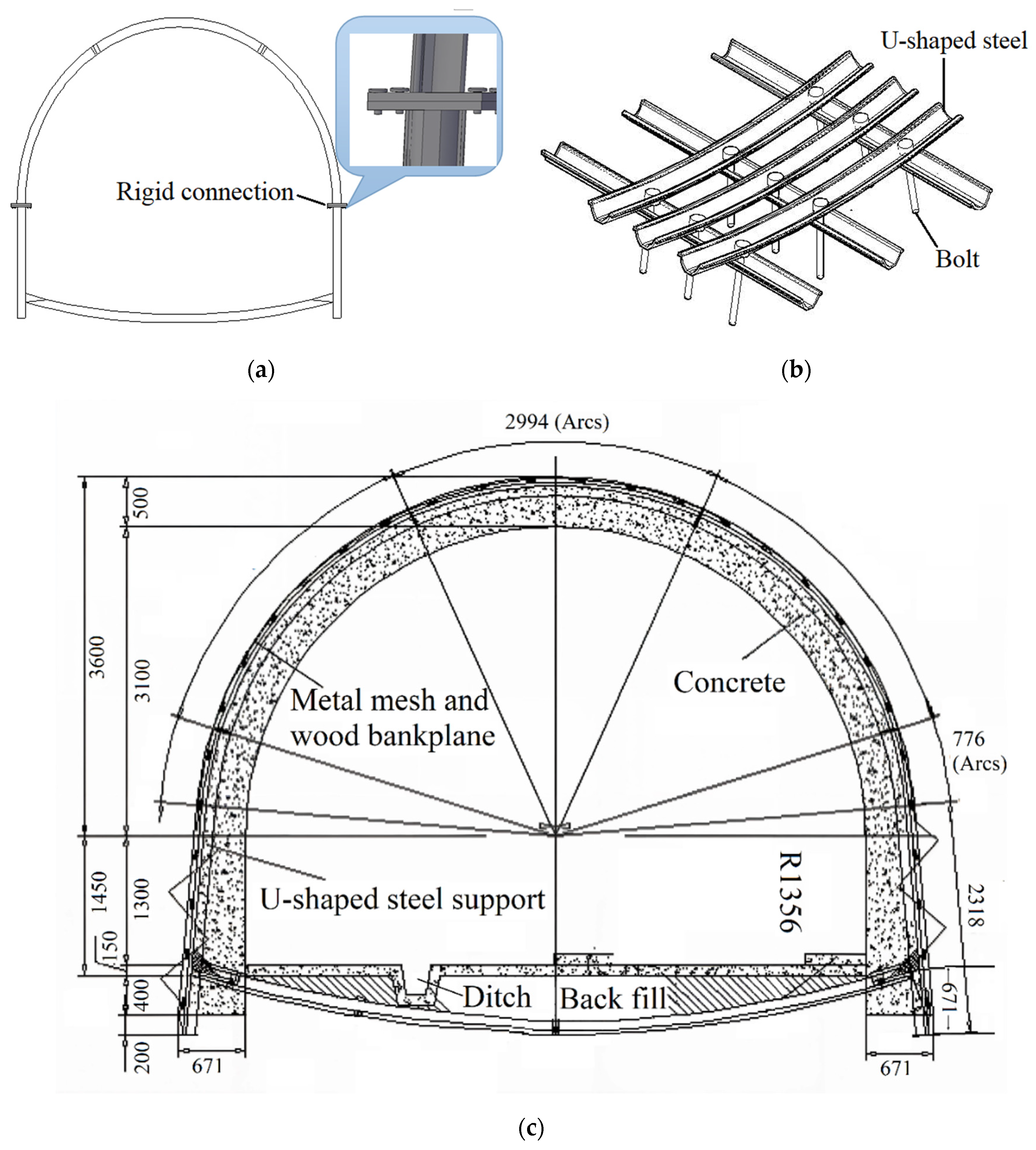
Through the top plate peeper in PingDingShan TianAn Coal Co., Ltd. No. 6 Mine’s new digging belt inclined shaft to identify the scope of perimeter rock loosening, the results show that in the distance from the inner wall of the roadway to 2.4 m in the perimeter rock, fissures are more developed, indicating that the perimeter rock’s broken degree is high, and 1.3 m and 2.1 m in the perimeter rock, the broken degree is large. Therefore, for the broken perimeter rock roadway, if the support for the shaft is not appropriately inclined, accidents will occur, which may cause two gangs of the broken rock body under the action of stress to move to the roadway floor, resulting in serious bottom drum. According to the characteristics of deformation and instability of the roadway in the mining area and theoretical analysis and calculation, the original support “anchor + anchor cable + anchor net spray” joint support technology cannot control the deformation and instability of the broken peripheral rock. The bottom drum phenomenon easily appears when this support is used. Therefore, in order to improve the stability of the broken perimeter rock, as well as the perimeter rock’s reinforcement arch-bearing characteristics and anti-bottom-drumming ability, we propose adopting the “U-shaped steel + inverted arch + bottom arch linkage beam + floor bolt compensation” joint support technology, i.e., the use of U-shaped steel support to improve the supporting structure of the degree of steel, so that the supporting structure is more effective in resisting the deformation of perimeter rock. Through the anti-bottom arch, a bottom arch chain beam and U-beam, combined to form a closed support structure with anchors fastened to the bottom plate as compensation, enhance the support structure to resist the bottom drum effect. The modified support steps are as follows:
- Laying of metal mesh; the size of the metal mesh is 40 × 40 mm, diameter is φ = 4 mm, and the construction requirements of the metal mesh must be close to the surface of the rock.
- Erection of wooden backboards with dimensions of 850 mm × 100 mm × 30 mm and spacing of 500 mm.
- Erection of rigid U36 steel braces with anti-bottom arches and steel connections between the braces to provide greater support resistance at the initial stage, thus improving the stability of the fractured perimeter rock. The spacing of each steel frame is 500 mm, and eight tie rods are provided. Between two neighboring anti-bottom arches, three U36 steel beams with a length of 1 m are set as the bottom arch interlocking beams. At the same time, three anchors are fastened to the bottom plate as compensation, which increases the overall stability of the steel frame.
- Pouring of concrete with thickness of 500 mm and concrete strength of C30.
The specific structure and support parameters are shown in Figure 4.

Figure 4.
(a) U-shaped steel bracket; (b) anti-bottom arch interlocking beams; (c) support program (unmarked numbers are measured in mm).
5. Numerical Simulation Analysis
5.1. Numerical Modeling
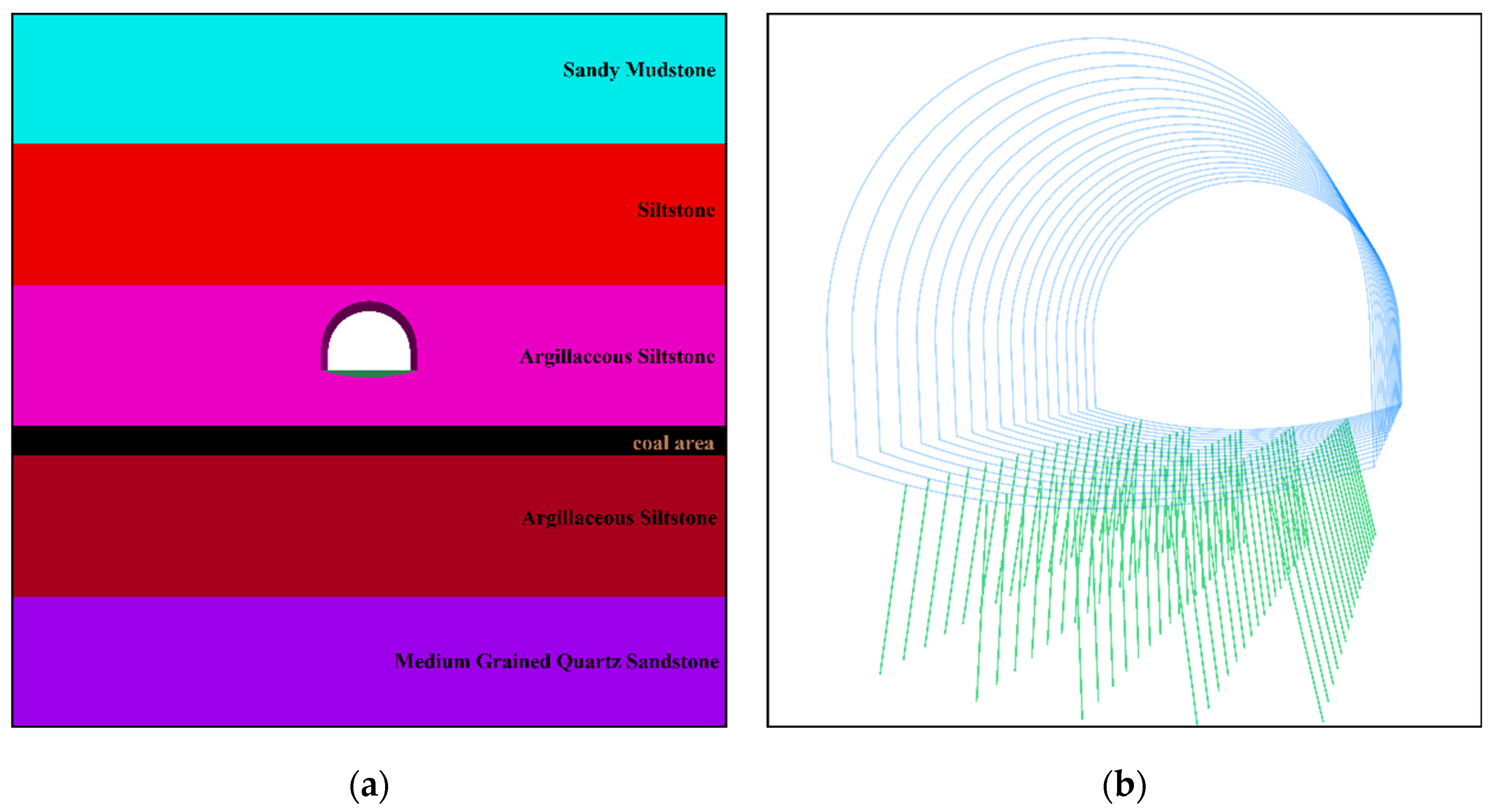
To verify the above theoretical analysis and provide a feasible basis for the optimized support scheme, the numerical simulation software FLAC3D (FLAC3D 6.0) was used to simulate the support scheme. The numerical model was established according to geological field information, as shown in Figure 5. The size of the model is 50 × 10 × 50, and the mechanical parameters of the layers are shown in Table 1.
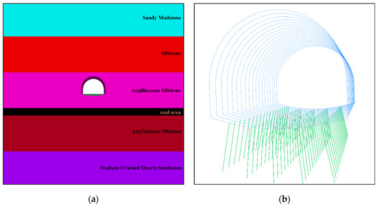
Figure 5.
Numerical analysis model diagram of FLAC3D: (a) numerical analysis model of rock formation; (b) numerical analysis model of support.

Table 1.
Mechanical parameters of rock formation.
5.2. Analysis of Numerical Simulation Results
The cloud diagram of the surrounding rock displacement before and after the optimization of the roadway support is shown in Figure 6 (Figure 7), and the amount of surrounding rock displacement is shown in Figure 8.
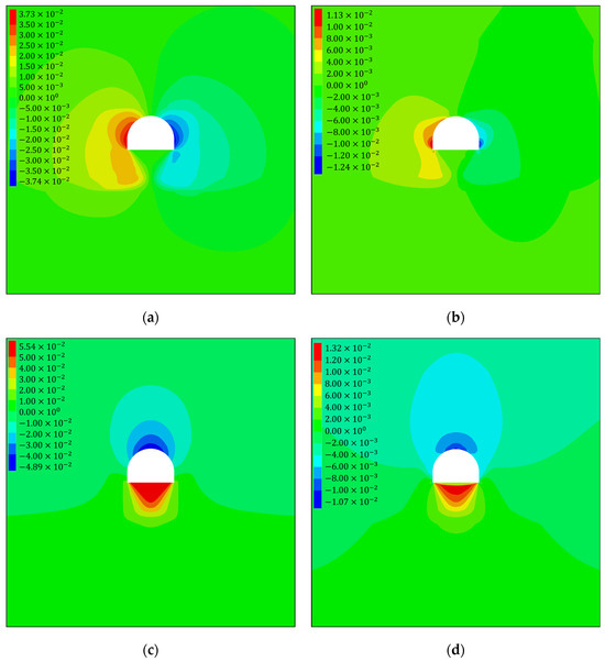
Figure 6.
Surrounding rock displacement nephogram: (a) horizontal displacement nephogram before optimization. (b) Horizontal displacement nephogram after optimization. (c) Vertical displacement nephogram before optimization. (d) Vertical displacement nephogram after optimization.
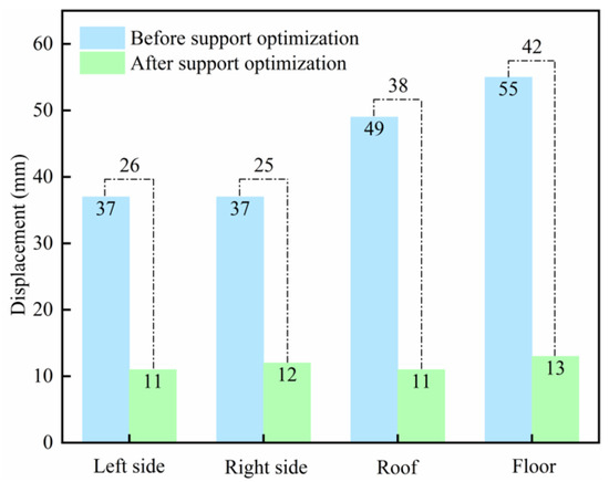
Figure 7.
Surrounding rock displacement.
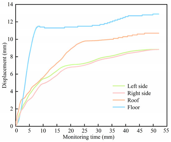
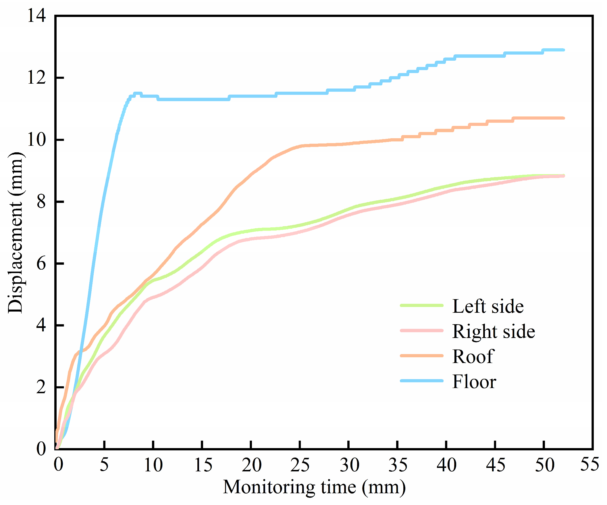
Figure 8.
Surrounding rock displacement monitoring curve.
From Figure 6 and Figure 7, it can be seen that before the optimization of the tunnel support, the horizontal displacement of the two gangs is 37 mm, the maximum subsidence of the top plate is 49 mm, and the maximum deformation of the bottom plate is 55 mm, which results in larger deformation of the bottom plate and easily occurs due to the broken peripheral rock of the roadway; the anchor rods and anchor ropes are weak when controlling the peripheral rock, which leads to the occurrence of the bottom bulge of the roadway. After the optimization of the tunnel support, the maximum horizontal displacement of the two gangs is 12 mm, the top plate sinking is 11 mm, and the maximum deformation of the bottom plate is 13 mm; compared with the pre-optimization conditions, the horizontal displacement of the two gangs is reduced by 70%, the top plate sinking is reduced by 77.5%, and the deformation of the bottom plate is reduced by 76.4%. Through the optimization of the tunnel support, the deformation of the surrounding rock tends to be uniformly distributed, and the stability of the broken surrounding rock is effectively controlled.
6. Numerical Simulation Analysis
To test the feasibility of the optimized joint support technology scheme and the effect of perimeter rock control, the monitoring points were set up in the two gangs and the top and bottom plates of the roadway by the “cross” distribution method, and perimeter rock displacement monitoring was carried out for 60 d; the results of the monitoring are shown in Figure 8. As shown in Figure 8, the maximum displacement of the two gangs is 10 mm, and the maximum displacement of the top and bottom plates is 13 mm, which verifies the feasibility of the optimized joint support technology scheme; the stability of the surrounding rock has been controlled efficiently, and the overall stability of the roadway has been improved greatly, which provides a safety guarantee for underground production.
7. Conclusions
Using the classical rock mechanics theory, a mechanical model of crushed perimeter rock in a roadway was established, the stress distribution law around the crushed rock perimeter in the roadway was systematically analyzed, and radial and tangential stress formulas for calculating the crushed rock perimeter were deduced. Through formula calculation, it was deduced that there was a stress drop in the intact surrounding rock outside the disturbed zone, and the radial stress of the intact surrounding rock in its deep part was relatively increased, while the tangential stress was relatively decreased. The existence of broken perimeter rock increased the minimum principal stress and reduced the maximum principal stress of the unbroken perimeter rock, which proves that the well-maintained broken zone could serve as lining, and these theoretical data are more consistent with the engineering practice.
According to the damage characteristics of the tunnel peripheral rock, the proposed “U-shaped steel + inverted arch + bottom arch linkage beam + floor bolt compensation” joint support technology makes the support structure and the peripheral rock realize a mutual coupling effect, such that the peripheral rock displacement is reduced significantly and tends to be uniformly distributed.
The on-site monitoring experiments show that under this support technology, the displacement of the two gangs of the roadway is only 10 mm, and the maximum displacement of the top and bottom plates is 13 mm; thus, the stability of the surrounding rock has been efficiently controlled, avoiding the problem of bottom drumming in the roadway and verifying the feasibility of this support technology program.
Author Contributions
Conceptualization, W.P. and S.F.; methodology, W.P. and S.F.; software, W.P. and S.F.; validation, W.P. and S.F.; formal analysis, W.P. and S.F.; investigation, W.P. and S.F.; resources, W.P.; data curation, W.P. and S.F.; writing—original draft preparation, W.P. and S.F.; writing—review and editing, S.F. All authors have read and agreed to the published version of the manuscript.
Funding
This research was supported by the Key Project of Hunan Provincial Education Department (22A0337). Supported by the Hunan Provincial Natural Science Found of China (2023JJ50232).
Institutional Review Board Statement
Not applicable.
Informed Consent Statement
Not applicable.
Data Availability Statement
The data used to support the findings of this study are available from the corresponding author upon request.
Acknowledgments
Thanks to PingDingShan TianAn Coal Co., Ltd. provides on-site support.
Conflicts of Interest
The authors declare no conflict of interest.
References
- Lu, C.; Dou, L.M.; Li, H.M. Research on the evaluation of relieve-shot effect by microseism. In Controlling Seismic Hazard and Sustainable Development of Deep Mines; Rinton Press: New York, NY, USA, 2009; Volume 1. [Google Scholar]
- Wang, W.; Peng, G.; Huang, J. Research on high-strength coupling support technology of high stress extremely soft rock roadway. J. China Coal Soc. 2011, 36, 223–228. [Google Scholar] [CrossRef]
- Meng, Q.; Song, Z.; Liu, B.; Huang, B.; Pu, H.; Wang, C.; Xin, X. Interaction Analysis of Surrounding Rock and Bolting-Shotcrete U-Shaped Steel Support Structure in Deep Soft Rock Roadway. Coal Sci. Technol. 2024, 52, 23–36. [Google Scholar] [CrossRef]
- Li, Y.; Pan, Y.; Li, Z. Analysis of mechanism of zonal disintegration of rocks. Chin. J. Geotech. Eng. 2006, 28, 1124–1128. [Google Scholar]
- Zhao, C.; Li, Y.; Liu, G.; Huang, S. Study on surrounding rock support technology of deep soft rock roadway. Coal Sci. Technol. 2022, 50, 76–84. [Google Scholar] [CrossRef]
- Meng, B.; Jing, H.; Wu, J.; Li, X.; Dong, J.; Yin, Q. Model test study on bearing mechanical properties of anchored gravels. Chin. J. Rock Mech. Eng. 2023, 42, 3020–3030. [Google Scholar] [CrossRef]
- Feng, G.; Ma, J.; Li, Z.; Qi, T.; Cui, J.; Guo, W.; Zhao, Y.; Hou, B. Bearing characteristics and damage mechanism of grouting reinforced body for broken surrounding rock. J. China Coal Soc. 2023, 48, 411–423. [Google Scholar] [CrossRef]
- Jager, J.C.; Cookn, G.W. Fundamentals of Rock Mechanics; Institute of Engineering Mechanics of Chinese Academy of, Translator; Science Press: Beijing, China, 1983; pp. 97–98. [Google Scholar]
- Zuo, J.; Liu, H.; Xu, C.; Wen, J.; Liu, D.; Zhu, F.; Ma, Z. Theory and technology of uniform strength support mechanics for deep coal roadway. J. China Univ. Min. Technol. 2023, 52, 625–647. [Google Scholar] [CrossRef]
- Luan, B.; Hua, X.; Li, H.; Zhang, C.; Zhang, Y. Study on stress evolution characteristics and surrounding rock stability of deep coal roadway through fault. Coal Technol. 2024, 43, 28–33. [Google Scholar] [CrossRef]
- Shemyakin, E.I.; Kurlenya, M.V.; Oparin, V.N.; Reva, V.N.; Glushikhin, F.P.; Rozenbaum, M.A.; Tropp, É.A. Zonal disintegration of around underground workings, part IV: Practical applications. J. Min. Sci. 1988, 24, 238–241. [Google Scholar]
- Shemyakin, E.I.; Fisenko, G.L.; Kurlenya, M.V.; Oparin, V.N.; Reva, V.N.; Glushikhin, F.P.; Rozenbaum, M.A.; Tropp, É.A.; Kuznetsov, Y.D. Zonal disintegration of around underground workings, part III: Theoretical concepts. J. Min. Sci. 1987, 23, 1–6. [Google Scholar]
- Adams, G.R.; Jager, A.J. Petroscopic observations of rock fracturing ahead of stope faces in deep-level gold mines. J.-S. Afr. Inst. Min. Metall. 1980, 80, 204–209. [Google Scholar]
- Zhang, B.; Zhang, Z.; Wang, B.; Zhou, L. Experimental study of application of yielding bolt to large deformation tunnel. Rock Soil Mech. 2016, 37, 2047–2055. [Google Scholar]
- Lian, C.; Xu, W.; Wang, Y.; Wang, Z. Numerical simulation of entry performance supported by a new high strength and high pretension yieldable bolts. Rock Soil Mech. 2010, 31, 2329–2335. [Google Scholar]
- Xie, W.; Jing, S.; Wang, T.; Ren, Y.; Zhang, N. Structural stability of U-steel support and its control technology. Chin. J. Rock Mech. Eng. 2010, 29, 3743–3748. [Google Scholar]
- Liu, J.; Zhang, N.; Zheng, X.; Wang, B. Research on buckling failure mechanism of U type steel support loaded deviating longitudinally. J. China Coal Soc. 2011, 36, 1647–1652. [Google Scholar]
- You, C. Stability analysis of U-steel yieldable support. Chin. J. Rock Mech. Eng. 2002, 21, 1672–1675. [Google Scholar]
- Wang, Q.; Xie, W.; Jing, S.; Zang, L. Research on U-shape steel frame and anchor cable collaborative support mechanism and loading law of roadway under dynamical pressure impact. Chin. J. Rock Mech. Eng. 2015, 40, 301–307. [Google Scholar]
- Liu, S.; Zhu, Q.; Jia, H.; Li, X. Characteristics and recognition of the dynamic response of strata interfaces to anchorage hole drilling in coal roadway roof. J. Min. Saf. Eng. 2017, 34, 748–759. [Google Scholar]
- Li, Y.; Zhang, D.; Song, Y.; Fang, Q.; Chen, F. Experimental Research of Progressive Damage of Surrounding Rock for Soft Fractured Deep Tunnel. Chin. J. Rook Mech. Eng. 2012, 31, 1138–1147. [Google Scholar]
- Yang, S.; Huang, Y.-H.; Jiao, Y.-Y.; Zeng, W.; Yu, Q.-L. An experimental study on seepage behavior of sandstone material with different gas pressures. Acta Mech. Sin. 2015, 31, 837–844. [Google Scholar] [CrossRef]
- Porras, R.; Carmona, J.R.; Yu, R.C.; Ruiz, G. Experimental study on the fracture of lightly reinforced concrete elements subjected to eccentric compression. Mater. Struct. 2016, 49, 87–100. [Google Scholar] [CrossRef]
- Zhang, Y. Failure modes analysis and control measures of fractured surrounding rocks for coal roadway. Coal Technol. 2019, 38, 41–45. [Google Scholar] [CrossRef]
- Sun, G.; Wang, P.; Feng, T.; Yu, W.; Yin, Z.; Jiang, Y.; Liu, H.; Li, L. Deformation mechanism and control technology of surrounding rock in soft and broken roof roadway. Coal Sci. Technol. 2020, 48, 209–215. [Google Scholar] [CrossRef]
- Li, G.; Ma, F.S.; Guo, J. Study on deformation failure characteristics and support methods in broken rock mass roadway under high geo-stress. Gold Sci. Technol. 2020, 28, 238–245. [Google Scholar]
- Zhou, Y.; Zhang, J.; Liu, Y.; Guo, Q.; Bo, Y.; Dong, J. Interaction between surrounding rock and support in deep broken roadway and support opportunity. Met. Mine 2022, 17–23. [Google Scholar] [CrossRef]
- Wang, X.; Cui, J.; Zhang, P.; Zhao, X. Support design and stability analysis of deep fractured roadway under static and dynamic condition. Met. Mine 2024, 17–23. [Google Scholar] [CrossRef]
- Liu, S.; Ning, J.; Shi, X.; Zhang, W.; Liu, S.; Xie, X. Optimization and application of bolting and grouting support parameters in roadway with fractured surrounding rock. Saf. Coal Mines 2024, 55, 181–189. [Google Scholar] [CrossRef]
- Bansal, R.K. A Textbook of Engineering Mechanics; Laxmi Publications: Hyderabad, India, 2005; p. 4. ISBN 978-81-7008-305-4. [Google Scholar]
- Yin, H.; Han, M.; Yu, J.; Wang, F. (Eds.) Theory and Experiment of Deep-Sea Thick-Walled Pipeline; Tianjin University Press: Tianjin, China, 2021. [Google Scholar]


Disclaimer/Publisher’s Note: The statements, opinions and data contained in all publications are solely those of the individual author(s) and contributor(s) and not of MDPI and/or the editor(s). MDPI and/or the editor(s) disclaim responsibility for any injury to people or property resulting from any ideas, methods, instructions or products referred to in the content. |
© 2024 by the authors. Licensee MDPI, Basel, Switzerland. This article is an open access article distributed under the terms and conditions of the Creative Commons Attribution (CC BY) license (https://creativecommons.org/licenses/by/4.0/).