Article

Research on the Design of Multi-Rope Friction Hoisting System of Vertical Shaft Gravity Energy Storage System

1
North China Power Engineering Co., Ltd. of China Power Engineering Consulting Group, Beijing 100120, China
2
School of Mechanical and Electrical Engineering, China University of Mining and Technology, Xuzhou 221116, China
3
School of Mechanical and Electrical Engineering, China University of Mining and Technology (Beijing), Beijing 100083, China
*
Author to whom correspondence should be addressed.
Appl. Sci. 2024, 14(17), 7556; https://doi.org/10.3390/app14177556
Submission received: 17 July 2024 / Revised: 19 August 2024 / Accepted: 23 August 2024 / Published: 27 August 2024

Abstract

:
Renewable energy generation methods such as wind power and photovoltaic power have problems of randomness, intermittency, and volatility. Gravity energy storage technology can realize the stable and controllable conversion of gravity potential energy and electric energy by lifting and lowering heavy loads. The hoisting system is an important component of a gravity energy storage system, and its lifting capacity and speed seriously restrict its energy storage capacity, energy conversion efficiency, and operational safety and reliability. In this paper, a design method for a multi-rope friction hoisting system of a vertical shaft gravity energy storage system is proposed. The parameter design and calculation of the hoisting rope, balance rope, and friction wheel of the friction hoisting system under typical conditions were carried out. The static and dynamic anti-slip capabilities of the friction hoisting system under the typical condition were explored. The results show that the maximum acceleration and deceleration speed of the compacted strand wire rope scheme is the largest, and the lifting and lowering time is the shortest. The maximum acceleration and deceleration speed of the triangular strand wire rope scheme is the lowest, and the lifting and lowering time is the longest. The dynamic tension of the hoisting rope at the heavy-load end is positively correlated with the acceleration, and the maximum value occurs in the accelerated lifting stage and decelerated lowering stage of the heavy load. The static anti-slip safety factor between the hoisting rope and the friction lining and the specific pressure between the hoisting rope and the friction lining comply with the requirements of China’s Safety Regulations for Coal Mines. The dynamic anti-slip safety factor of the hoisting system under different rope selection schemes is greater than the minimum value of 1.25 stipulated in the Safety Regulations for Metal and Nonmetal Mines. The research results are of great significance for the safety, reliability, and stable and efficient energy storage of a gravity energy storage system.

1. Introduction

In order to realize the goal of “carbon peaking and carbon neutrality”, the construction of a new type of power system has become the main direction of China’s energy structure transformation [1,2,3,4]. However, the randomness, intermittency, and volatility of renewable energy generation, such as that from wind power and photovoltaic power, pose challenges when integrating large-scale renewable energy into the power system. This results in issues like insufficient power consumption and resource waste [5]. Compared with wind power and photovoltaic power generation methods, gravity energy storage technology has the advantages of large application scale, high conversion efficiency, low cost, long service life, not being affected by the environment, long energy storage time, and no self-discharge. It can realize stable and controllable conversion between gravitational potential energy and electric energy by lifting and lowering heavy loads cyclically through a hoisting system [6], which is suitable for grid peaking and realizing day and night transfer of electric energy, and is of great significance for maintaining the stability of a high proportion of renewable energy power systems [7].
A vertical shaft gravity energy storage system (Figure 1) mainly includes a weight block, a hoisting system, an energy conversion system, and a power grid connection system. The hoisting system realizes the reciprocal lifting and lowering of weights in a wide range of transport distances for energy storage and release. At the same time, the energy conversion system achieves the mutual conversion of mechanical energy and electric energy, and then the electrical energy is integrated into the power grid. The hoisting system is the core component of the gravity energy storage system, and its lifting capacity and lifting speed seriously restrict its capacity, energy conversion efficiency, and operational safety and reliability. Therefore, the design of a friction hoisting system for gravity energy storage system is crucial.
In the process of energy storage, the permanent magnet motor drives the friction wheel to rotate, and the friction between the steel wire rope and the friction lining on the friction wheel drives the loaded cage and the unloaded cage to rise and fall alternately. When the loaded cage is hoisted to the wellhead for unloading, the unloaded cage is lowered to the bottom of the mine for loading. Then, the loaded cage is hoisted again by friction to the wellhead for unloading, while the original loaded cage becomes empty and is lowered to the bottom of the mine for the next loading. In the process of energy release, the loaded cage is lowered under the motor assistance and the action of gravity, and the friction between the steel wire rope and the friction lining on the friction wheel drives the friction wheel to rotate. When the loaded cage is lowered to the bottom of the mine for unloading, the unloaded cage is hoisted to the wellhead for loading. Subsequently, the loaded cage is again lowered to the bottom of the mine for unloading under the motor assistance and the action of gravity, while the original loaded cage becomes empty and raised to the wellhead for the next loading.
The gravity energy storage system is still in the preliminary research stage at home and abroad. Research teams in Europe and the United States have carried out in-depth exploration in the mechanical structure innovation of the hoisting system, such as the use of advanced materials and manufacturing processes to design high-strength and lightweight hoisting parts to reduce energy loss. Part of the research focuses on the development of novel driving mechanisms, such as the use of superconducting magnetic levitation technology to reduce friction resistance and improve lifting efficiency. In addition, many universities and research institutes have carried out theoretical analysis and calculation for the mechanical model and energy conversion efficiency of the hoisting system. By establishing mathematical models, researchers have discussed the system performance and optimization methods under different lifting methods to improve the traditional hoisting technology, such as optimizing the performance of the motor and improving the structure of the transmission device so as to improve the reliability and stability of the system, as well as conducting basic research on new hoisting technologies, such as exploring the use of linear motors or electric cylinders to achieve hoisting functions. In 2013, Fraenkel Weight in the UK proposed a gravity energy storage scheme based on a single winch hoist [8]. In 2018, Gezhouba Zhongke Energy Storage Technology Co., Ltd. proposed a gravity energy storage scheme using a mine elevator to hoist a single heavy load [9]. In 2019, the China Coal Energy Research Institute proposed a gravity energy storage scheme using a mine elevator to hoist multiple heavy loads [10]. In 2020, Gravitricity in the UK proposed a gravity energy storage scheme based on multiple winch hoists to hoist single or multiple heavy loads [11], and completed a 250 kW principle demonstration system test with a 15 m-deep drilling platform [12]. In 2021, American scholars proposed a gravity energy storage scheme for hoisting multiple heavy loads in a vertical shaft using two independent winch hoists [13]. In 2021, the Institute of Electrical Engineering of the Chinese Academy of Sciences proposed a gravity energy storage scheme based on hoisting multiple weights with a gantry hoist [14,15,16]. In the scheme, automatic hoisting devices or cages are used to achieve the hoisting of multiple heavy loads, and multiple heavy objects are placed horizontally in the roadway or vertically stacked in the shaft. Xiao et al. [17] put forward the scheme of building an energy storage tower in a vertical or inclined shaft, and listed their respective application scenarios.
The existing research is still in the conceptual stage of designing a vertical shaft gravity energy storage system with light load and low lifting height, and there has been no research on the design of a vertical shaft gravity energy storage friction hoisting system under kilometer-level, large transportation distance, large load, and high lifting speed conditions. Therefore, a design method for a vertical shaft gravity energy storage friction hoisting system is proposed herein. The parameters of the hoisting rope, balance rope, friction wheel, and derrick of the friction hoisting system under the typical hoisting condition were calculated. The static and dynamic anti-slip capabilities of the friction hoisting system under typical hoisting conditions were investigated. The research results have definite guiding significance for the design of a multi-rope friction gravity energy storage system and ensuring the safety and stability of the system.

2. Design Theory of Multi-Rope Friction Hoisting System with Double Cages in Vertical Shaft

The multi-rope friction hoisting system is an important component of the shaft gravity energy storage system, which is mainly responsible for lifting and lowering heavy loads in the process of energy storage and release. The system is mainly composed of a sheave wheel, hoisting rope, derrick, friction wheel, double cages, and balance rope (Figure 2).

2.1. Calculation Theory and Selection of the Structural Parameters of the Hoisting System

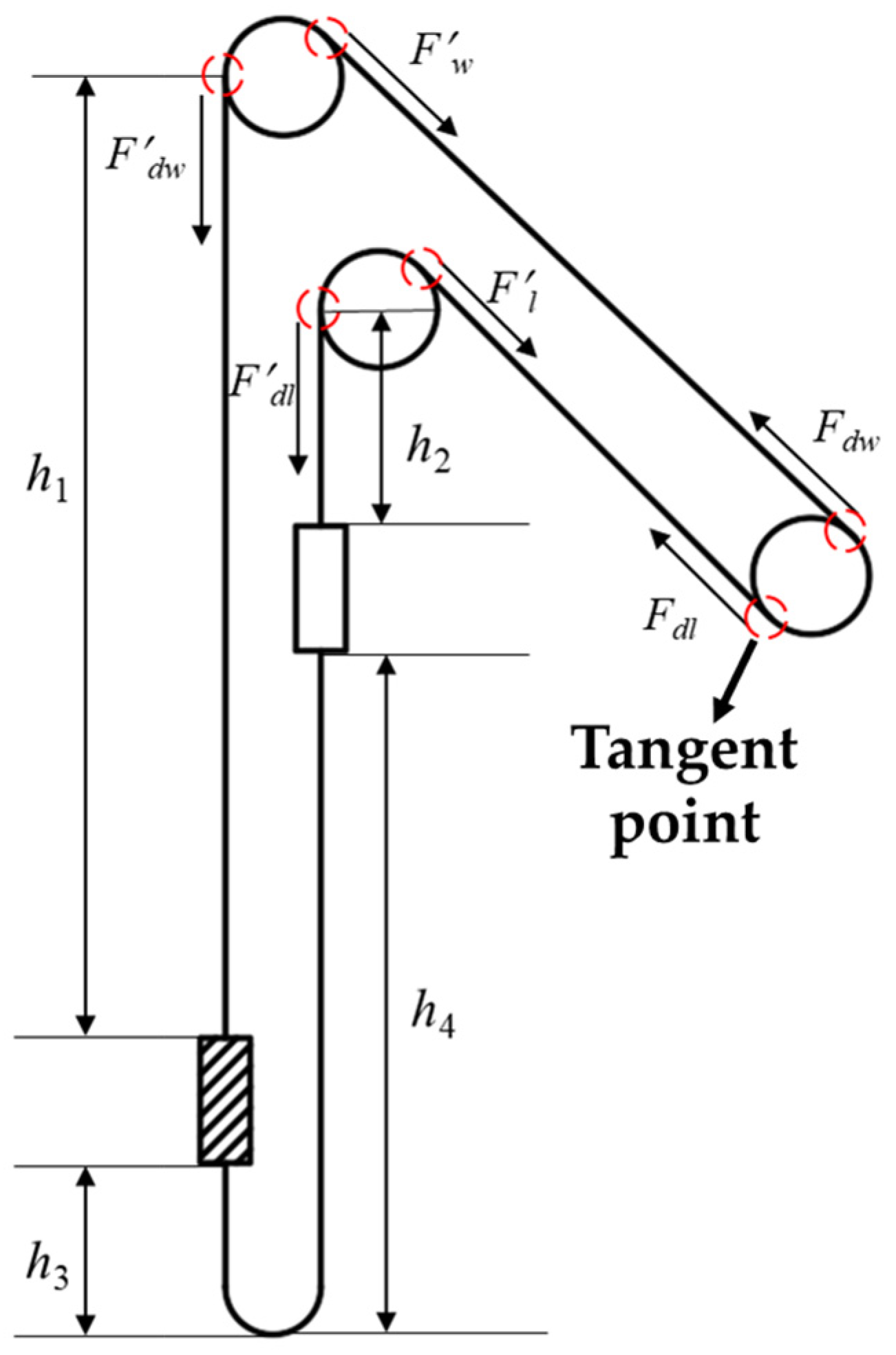
2.1.1. Calculation of Chord Length and Elevation Angle of Upper and Lower Ropes

The calculation formulas for the chord lengths of the upper rope and lower rope Ls and Lx are shown in Equations (1) and (2).
L s = ( H j E 0 ) 2 + ( L 0 + S D t 2 ) 2 ( D g D t 2 ) 2
L x = ( H j H s E 0 ) 2 + ( L 0 D t 2 ) 2 ( D t + D g 2 ) 2
The calculation formulas for the elevation angle of the upper rope and lower rope βs and βx are shown in Equations (3) and (4):
β s = arctan ( H j E 0 L 0 + S D t 2 ) arctan ( D g D t 2 L s )
β x = arctan ( H j H s E 0 L 0 D t 2 ) arctan ( D g + D t 2 L x )
where E0 is the vertical height from the center of the friction wheel to the level of the wellhead lock (rail surface), Hj is the vertical height from the center of the friction wheel to the lock of the wellhead, L0 is the horizontal distance from the center of the friction wheel to the right vertical rope, S is the center distance of the left and right vertical rope, Dt is the diameter of the upper sheave wheel and lower sheave wheel, and Dg is the diameter of the drum.

2.1.2. Calculation of Parameters of Friction Wheel

The calculation formula for the wrapping angle of the hoisting wire rope on the friction lining α is shown in Equation (5):
α = 180 ° + β x β s
where βs is the elevation angle of the upper rope and βx is the elevation angle of the lower rope.
According to Article 417 of China’s Safety Regulations for Coal Mines [18], the ratio of the minimum diameter of the sheave wheel, drum, friction wheel, and guide wheel to the diameter of the steel wire rope should meet the requirements in Table 1.
In addition, according to Safety Inspections—Testing Specifications of In-Service Friction Hoist System for Coal Mines [19], the ratio of the diameter of the sheave wheel, friction wheel, and guide wheel to the diameter of the thickest steel wire in the steel wire rope should not be less than 1200.
A floor-standing multi-rope friction hoisting system was designed and the method of installation on the well was adopted. The ratio of the diameter of the friction wheel, sheave wheel, and hoisting rope in this system should all meet Equations (6) and (7):
D 1 d 90
D 1 δ 1200
where D1 is the diameter of the friction wheel and sheave wheel, d is the nominal diameter of the hoisting rope, and δ is the diameter of the thickest steel wire in the hoisting rope.
According to the requirements of Formulas (6) and (7) and combined with the basic parameters of the floor-standing multi-rope friction elevator in GB/T10599-2023 (Multi-rope friction hoist) [20], the appropriate diameter of friction wheel and the rope groove spacing of the friction wheel is selected.

2.2. Calculation Theory and Selection of Hoisting Rope and Tail Rope

2.2.1. Initial Overhang Height of Hoisting Rope and Tail Rope

The initial position of the cage in this system is at the bottom of the vertical shaft, and there is a certain height difference between the left and right sheave wheels. Therefore, it is necessary to calculate the initial overhang height of the hoisting ropes and tail ropes on both sides separately.
When the heavy-load end is the left cage, the initial overhang height of the hoisting rope at the heavy-load end h1, the initial overhang height of the hoisting rope at the light-load end h2, the initial overhang height of the tail rope at the heavy-load end h3, and the initial overhang height of the tail rope at the light-load end h4 are shown in Equations (8)–(11).
h 1 = H + H t 1 h
h 2 = H t 2 h
h 3 = H 0 + H g + H h
h 4 = H + H g + H h h H 0
When the heavy-load end is the right cage, the initial overhang height of the hoisting rope at the heavy-load end h1, the initial overhang height of the hoisting rope at the light-load end h2, the initial overhang height of the tail rope at the heavy-load end h3, and the initial overhang height of the tail rope at the light-load end h4 are shown in Equations (12)–(15):
h 1 = H + H t 2 h
h 2 = H t 1 h
h 3 = H g + H h
h 4 = H + H g + H h h
where H is the target hoisting height, Ht1 is the height of the sheave wheel at the heavy-load end, Ht2 is the height of the sheave wheel at the light-load end, h is the height of the cage, H0 is the hoisting height at a certain time, Hg is the height of overwind, and Hh is the height of the tail rope ring.

2.2.2. Approximate Unit Weight and Minimum Breaking Force of Hoisting Rope

According to GB/T 8918-2006 (Steel wire ropes for important purposes) [21], the approximate unit weight of wire rope pk and the minimum breaking force of wire rope F0 are calculated through Formulas (16) and (17):
P k = K 1 d 2 100
where d is the nominal diameter of the wire rope and K1 is the mass coefficient of the wire rope and:
F 0 = K 2 d 2 R 0
where K2 is the minimum breaking tension coefficient of the wire rope, d is the nominal diameter of the wire rope, and R0 is the nominal tensile strength of the wire rope.

2.2.3. Minimum Nominal Diameter of Hoisting Wire Rope

According to an empirical formula [22] of wire rope diameter selected in the design manual, the calculation formula for the minimum diameter of the hoisting wire rope dmin is shown in Equation (18):
d min = 100 Q d n 1 K 1 ( K z R 0 m a h 1 ) π
where Qd is the end load of the rope, N1 is the number of hoist ropes, K1 is the mass coefficient of the wire rope, Kz is the comprehensive coefficient of the wire rope, and its formula is K z = 100 K 2 K 3 K 1 g , R0 is the nominal tensile strength of the wire rope, ma is the minimum safety coefficient of wire rope stipulated in the Safety Regulations for Coal Mines, and h1 is the initial overhang height of the hoisting rope at the heavy-load end.

2.2.4. Safety Coefficient of Hoisting Wire Rope

According to Article 408 of the Safety Regulations for Coal Mines, the safety coefficient of hoisting steel wire ropes must meet the requirements in Table 2.
The multi-rope friction hoisting system (floor-standing) for a vertical shaft gravity energy storage system was adopted, and was specially designed for lifting materials. The calculation formula of the minimum safety coefficient of the wire rope ma is shown in Equation (19):
m a = 7.2 0.0005 H
where H is the lifting height.
According to the Safety Regulations for Coal Mines, the safety coefficient of the steel wire rope is the ratio of the sum of breaking force of the qualified steel wire to the maximum static tension Fmax (Equation (20)), so the calculation formula of the safety coefficient of the steel wire rope is shown in Equation (21):
F max = ( Q d + n 1 p k h 1 + n 2 q k h 3 ) g
m = n 1 K 3 F 0 F max m a
where Qd is the end load of the rope, n1 is the number of hoist ropes, n2 is the number of tail ropes, pk is the unit weight of the hoisting rope, qk is the unit weight of the tail rope, h1 is the initial overhang height of the hoisting rope at the heavy-load end, h3 is the initial overhang height of the tail rope at the heavy-load end, m is the safety coefficient of the steel wire rope, ma is the minimum safety coefficient of wire rope stipulated in the Safety Regulations for Coal Mines, and K3 is the conversion factor of the minimum breaking force of the wire rope.

2.2.5. Type Selection of Hoisting Wire Rope

According to the calculation results of the minimum diameter of the hoisting wire rope (Equation (18)) and the minimum safety coefficient stipulated in the Safety Regulations for Coal Mines (Equation (19)), combined with the selection standards of the wire rope in GB/T 8918-2006 (Steel wire ropes for important purposes) and YB/T 5359-2020 (Compact-ed strand ropes) [23], the appropriate type and diameter of the wire rope is selected and the safety coefficient according to the Equation (21) is checked to ensure that the safety coefficient of the hoisting wire rope is greater than the minimum value specified in the Safety Regulations for Coal Mines.

2.2.6. Type Selection of Balance Tail Rope

There are three main types of balance tail rope. The advantage of multi-layer profiled-strand (nonrotating) steel wire rope is that it has a small rotational torque during operation, but the disadvantage is that it is difficult to check for broken wires in the inner strand, and the outer strand is prone to loosening during operation. The advantages of flat steel wire rope are small transverse vibration amplitude, no rotation, and stable and reliable operation. The disadvantage is that the flat steel wire rope is generally manually woven, so it is expensive. Ordinary point contact around strand steel wire ropes can also be used as balance tail ropes, such as 6 × 19, 6 × 37, which have the advantages of low price and sufficient supply. The disadvantage is that the round strand steel wire rope is prone to knotting at the tail rope ring [24].
The selection of balance tail ropes is based on the equal weight tail rope balance scheme [5], which means that the total weight of n1 hoisting steel wire ropes with unit length is equal to the total weight of n2 balance tail ropes with unit length, as shown in Equation (22):
q k = n 1 n 2 p k
where qk is the unit weight of a tail rope, pk is the unit weight of a hoisting rope, n1 is the number of hoisting ropes, and n2 is the number of tail ropes.
According to the calculation result based on Equation (22) and the selection standard of a balance tail rope in GB/T 20119-2023 (Steel wire ropes for balance) [25], the appropriate balance tail rope is selected.

2.3. Static Calculation Theory of Hoisting System

2.3.1. Static Tension Calculation of Hoisting Wire Rope

The hoisting system of the shaft gravity energy storage system is a multi-rope friction hoisting system with double cages (floor-standing). The structure diagram of the hoisting system in the static state is shown in Figure 3. Since the system adopts a double-cage hoisting scheme, and the initial overhang heights of the hoisting wire ropes and tail ropes on both sides of the wheel are different, it is necessary to consider the force conditions of the hoisting system when the heavy load is loaded in different cages. Additionally, due to the use of an equal-weight balanced tail rope scheme (n1pk = n2qk), the static tension at the tangent point of the friction wheel remains approximately constant throughout the hoisting process (assuming the overhang height of hoisting wire rope at the heavy-load end is hc at a certain moment, the overhang height of tail rope is hw, and the hoisting height is Δh, then n1pk(hc − Δh) + n2qk(hw + Δh) = n1pkhc + n2qkhw, with the same principle applying to the light-load end). Therefore, when calculating the static tension of hoisting wire rope, it is only necessary to calculate the static tension at the tangent point of the friction wheel of the hoisting system in its initial position.
When the left-side cage is the heavy-load end, the static tension at the tangent point of the friction wheel at the heavy-load end Fjw and the static tension at the tangent point of the friction wheel at the light-load end Fjl can be calculated through Equations (23) and (24).
F j w = [ n 1 q k ( h 1 L s sin β s ) + n 2 p k h 3 + 1000 ( Q + Q z ) ] g
F j l = [ n 1 q k ( h 2 L x sin β x ) + n 2 p k h 4 + 1000 Q z ] g
When the right-side cage is the heavy-load end, the static tension at the tangent point of the friction wheel at the heavy-load end Fjw and the static tension at the tangent point of the friction wheel at the light-load end Fjl can be calculated through Equations (25) and (26):
F j w = [ n 1 q k ( h 1 L x sin β x ) + n 2 p k h 3 + 1000 ( Q + Q z ) ] g
F j l = [ n 1 q k ( h 2 L s sin β s ) + n 2 p k h 4 + 1000 Q z ] g
where n1 and n2 are the number of hoisting ropes and tail ropes, pk is the unit weight of the hoisting rope, qk is the unit weight of the tail rope, h1 is the initial overhang height of the hoisting rope at the heavy-load end, h2 is the initial overhang height of the hoisting rope at the light-load end, h3 is the initial overhang height of the tail rope at the heavy-load end, h4 is the initial overhang height of the tail rope at the light-load end, Ls and Lx are the chord lengths of the upper rope and lower rope, βs and βx are the elevation angles of the upper rope and lower rope, Q is the lifting load, Qz is the weight of the hoisting container, and g is the acceleration due to gravity.
The values h1, h2, h3, h4 are calculated by Equations (8)–(11) or (12)–(15) according to the position of the heavy-load.

2.3.2. Calculation of the Static Anti-Slip Safety Coefficient between Hoisting Rope and Friction Lining

The multi-rope friction hoisting system utilizes the friction between the wire rope and the friction linings on the friction wheel to transmit motion. According to Euler’s formula for flexible body friction transmission, the ratio of the wire rope tensions on both sides of the friction wheel should satisfy Equation (27) to prevent slipping:
F j l F j w e μ α
where Fjw is the static tension at the tangent point of the friction wheel at the heavy-load end, Fjl is the static tension at the tangent point of the friction wheel at the light-load end, μ is the friction coefficient between the friction lining and the wire rope, and α is the wrapping angle of the hoisting rope on the friction lining.
According to GB 16423-2020 (Safety regulation for metal and nonmetal mines) [26], the static anti-slip safety coefficient δ is defined as the ratio of the force preventing the wire rope from slipping (static friction force) to the difference in tension of the wire rope on both sides of the friction wheel. Thus, the static anti-slip safety coefficient δ can be calculated using Equation (28).
δ = F j l ( e μ α 1 ) F j w F j l
Additionally, GB 16423-2020 (Safety regulation for metal and nonmetal mines) stipulates that the static anti-slip safety coefficient for a multi-rope friction hoisting system should not be less than 1.75, thus δ ≥ 1.75.

2.3.3. Calculation of Contact Pressure between Hoisting Rope and Friction Lining

The contact pressure between the hoisting rope and the friction lining can be calculated using Equation (29):
P = F j w + F j l n 1 d D g
where Fjw is the static tension at the tangent point of the friction wheel at the heavy-load end, Fjl is the static tension at the tangent point of the friction wheel at the light-load end, n1 is the number of hoisting ropes, d is the nominal diameter of the hoisting rope, and Dg is the diameter of the friction wheel.
Additionally, the contact pressure between the wire rope and the friction lining P should not exceed 2 Mpa according to the Safety Regulations for Coal Mines.

2.4. Dynamic Calculation Theory of Hoisting System

2.4.1. Equivalent Mass of the Hoisting System

The hoisting system is a complex motion system. The d’Alembert principle is used to simplify the calculation of the system’s inertial forces. The mass of moving components (wire ropes, sheave wheels, friction wheels, motors, cages, heavy loads) are replaced with a concentrated mass at the friction wheel. This equivalent mass is referred to as the hoisting system’s equivalent mass.
The total equivalent mass ΣM of the system can be calculated using Equation (30) [27].
M = Q + 2 Q z + n 1 p k L c + n 2 q k L w + N m t + m j + m d
When the left-side cage is the heavy-load end and located at the initial bottom position of the shaft, the maximum equivalent mass at the heavy-load end mw and the minimum equivalent mass at the light-load end ml can be calculated using Equations (31) and (32).
m w = Q + Q Z + n 1 p k ( L x + h 1 ) + n 2 q k h 3 + m t
m l = Q Z + n 1 p k ( L s + h 2 ) + n 2 q k h 4 + m t
When the right-side cage is the heavy-load end and located at the initial bottom position of the shaft, the maximum equivalent mass at the heavy-load end mw and the minimum equivalent mass at the light-load end ml can be calculated using Equations (33) and (34):
m w = Q + Q Z + n 1 p k ( L x + h 1 ) + n 2 q k h 3 + m t
m l = Q Z + n 1 p k ( L s + h 2 ) + n 2 q k h 4 + m t
where Q is the lifting load, Qz is the weight of the hoisting container, Lc is the total length of the hoisting rope, Lw is the total length of the tail rope, pk is the unit weight of the hoisting rope, qk is the unit weight of the tail rope, n1 and n2 are the number of hoisting ropes and tail ropes, N is the number of sheave wheel, mt is the equivalent mass of the sheave wheel, mj is the equivalent mass of the friction wheel, md is the equivalent mass of the motor, Ls is the chord length of the upper rope, Lx is the chord length of the lower rope, h1 is the initial overhang height of the hoisting rope at the heavy-load end, h2 is the initial overhang height of the hoisting rope at the light-load end, h3 is the initial overhang height of the tail rope at the heavy-load end, and h4 is the initial overhang height of the tail rope at the light-load end.

2.4.2. Limiting Acceleration/Deceleration

The maximum acceleration/deceleration of the hoisting system can be calculated using Equation (35). Since only the inertial force caused by equivalent mass is considered in the calculation process and the mine resistance is ignored, a certain safety margin should be left for the calculation result, that is, amax = 0.8·a.
a ( e μ α 1 ) F j l δ d min ( F j w F j l ) ( e μ α 1 ) m l + δ d min ( m l + m w )
where δdmin is the minimum dynamic anti-slip safety coefficient for the multi-rope friction hoisting system, 1.25, Fjw is the static tension at the tangent point of the friction wheel at the heavy-load end, Fjl is the static tension at the tangent point of the friction wheel at the light-load end, mw is the maximum equivalent mass at the heavy-load end, ml is the minimum equivalent mass at the light-load end, μ is the friction coefficient between the friction lining and the wire rope, and α is the wrapping angle of the hoisting rope on the friction lining.

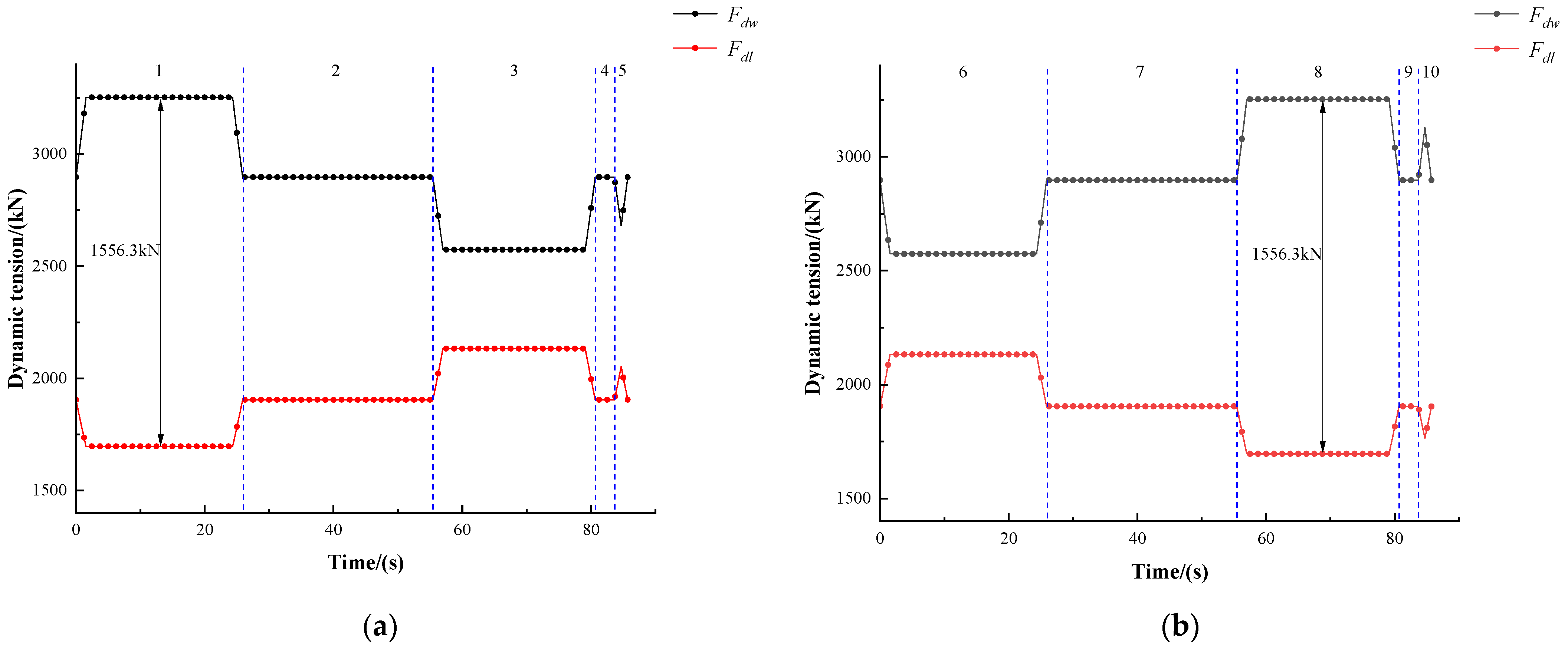
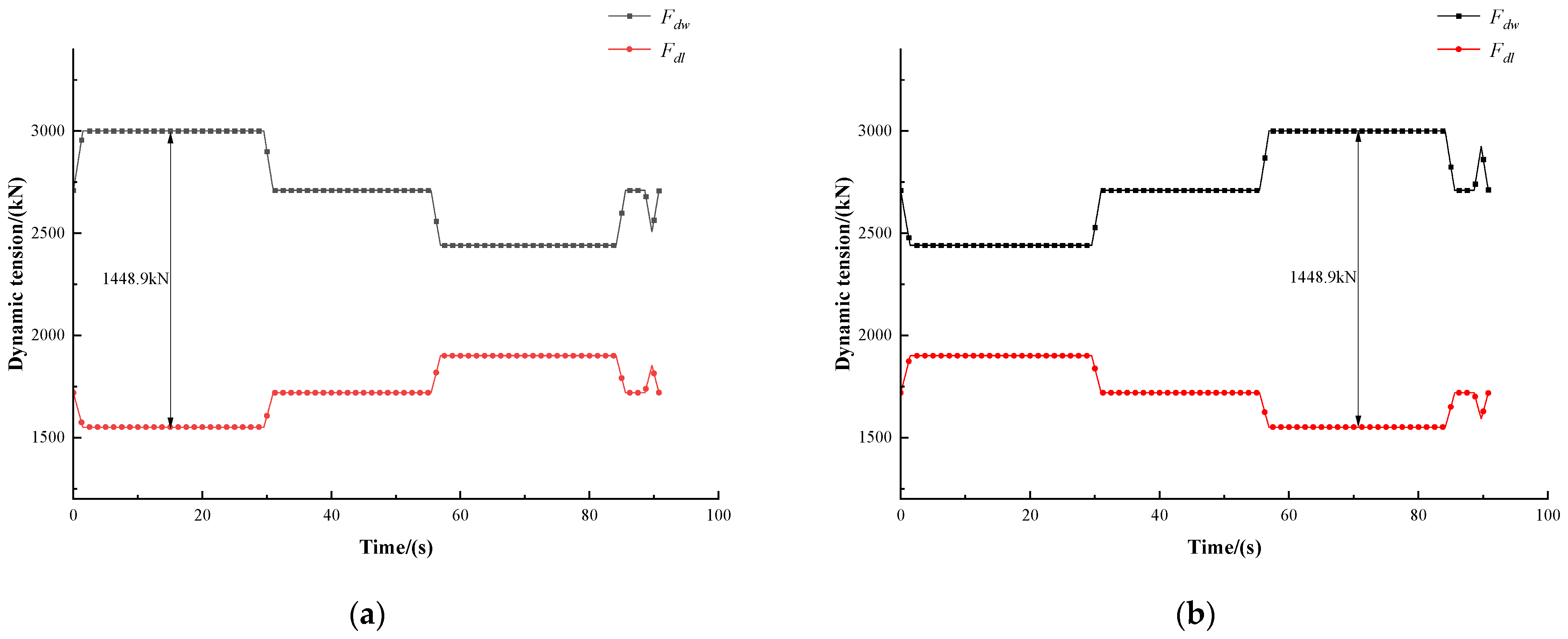
2.4.3. Dynamic Tension of the Hoisting Rope

During the hoisting and lowering processes of heavy loads, several sources of resistance affect the operation of the system, including air resistance, resistance between the cage and the guide rail, and bending resistance between the rope and sheave wheels or friction wheels. The specific resistance coefficients for each condition cannot be precisely determined due to these resistances. Therefore, the resistances can be neglected in the calculations, but a safety margin of 10% to 20% should be added to the computed parameters.
In this study, the dynamic tension of the hoisting rope during the energy storage and release of the shaft gravity energy storage system is calculated considering only the inertial forces caused by the equivalent mass. The influence of mine resistance and elastic vibration of wire ropes is neglected. Since there are multiple stages during the energy storage and release processes, as shown in Figure 4 and Figure 5, and the hoisting system employs a double-cage hoisting scheme, dynamic tension analysis must be performed for the hoisting rope at different loading positions and stages.
According to the dynamic model in Figure 4 and Figure 5, the stress of the hoisting rope at the sheave wheel and friction wheel is analyzed, as shown in Figure 6. Under different working conditions, the dynamic tension at the left tangent points between the rope and the upper and lower sheave wheels is calculated by Equations (36) and (37). The dynamic tension at the right tangent points between the rope and the upper and lower sheave wheels is calculated by Equations (38) and (39). The dynamic tension at the tangent points on both sides of the friction wheel is shown in Equations (40) and (41).
F d w = [ ( Q + Q z ) + ( n 1 p k h 1 + n 2 q k h 3 ) / 1000 ] · [ g + a ]
F d l = [ Q z + ( n 1 p k h 2 + n 2 q k h 4 ) / 1000 ] · [ g a ]
F w = ( 1 + a g ) F d w + k 1 F c + a g × G t
F l = ( 1 a g ) F d l + k 1 F c + a g × G t
F d w = F w m s sin β s a + m j + m d 2 a
F d l = F l + m x sin β x a m j + m d 2 a
where n1 and n2 are the number of hoisting ropes and tail ropes, pk is the unit weight of the hoisting rope, qk is the unit weight of the tail rope, h1 is the initial overhang height of the hoisting rope at the heavy-load end, h2 is the initial overhang height of the hoisting rope at the light-load end, h3 is the initial overhang height of the tail rope at the heavy-load end, h4 is the initial overhang height of the tail rope at the light-load end, Ls is the chord length of the upper rope, Lx is the chord length of the lower rope, βs is the elevation angle of the upper rope, βx is the elevation angle of the lower rope, g is the acceleration due to gravity, a is the acceleration of hoisting system, Fc is the static tension difference on both sides of the friction wheel, calculated by Fc = FjwFjl, k1 is the resistance coefficient, taken as 0.1, Q is the lifting load, Qz is the weight of the hoisting container, Gt is the equivalent mass of the sheave wheel, ms is the mass of the upper rope, mx is the mass of the lower rope, mj is the equivalent mass of the friction wheel, md is the equivalent mass of the motor, mw is the maximum equivalent mass of the heavy-load end, and ml is the maximum equivalent mass of the light-load end.

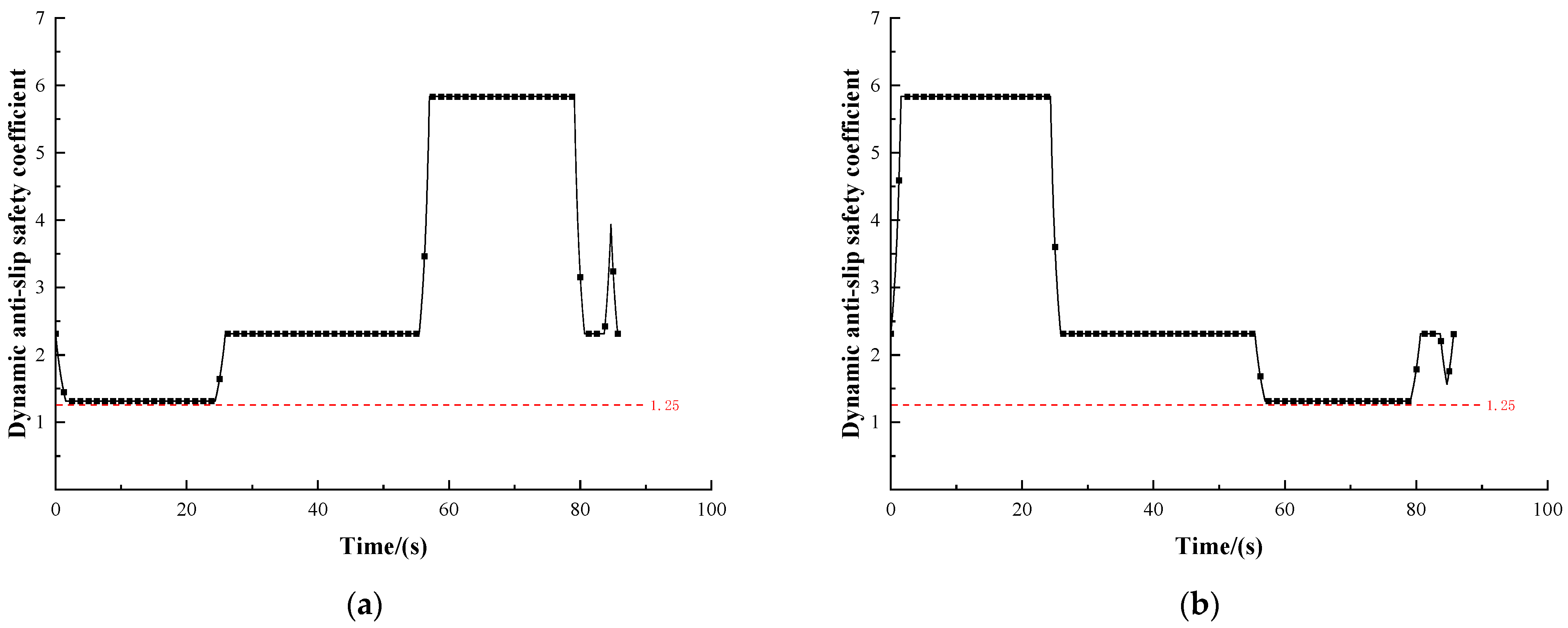
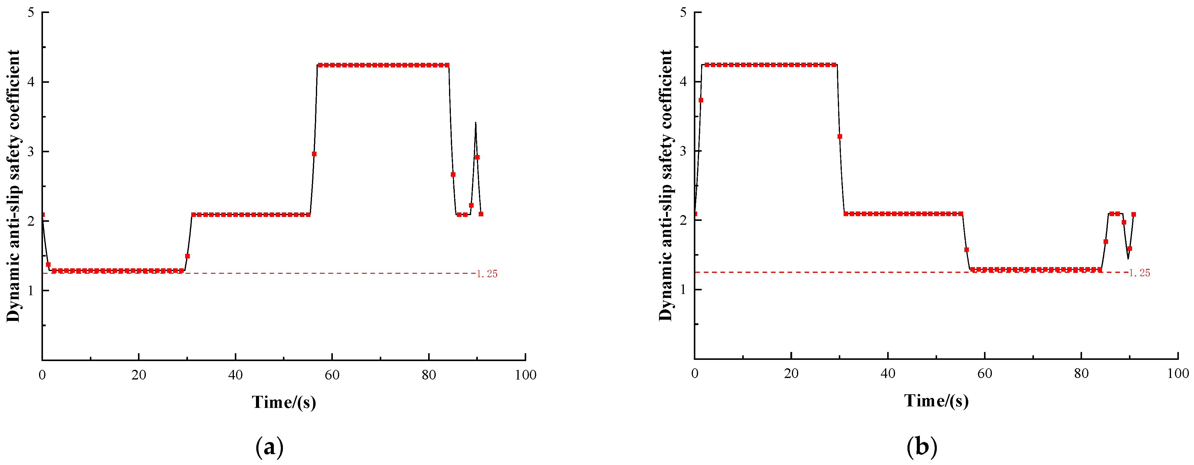
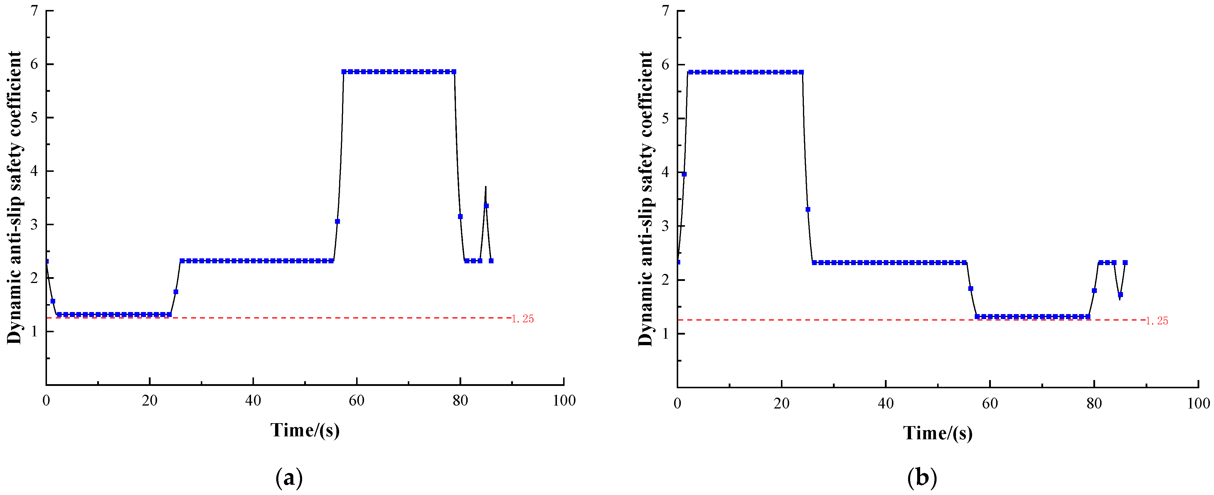
2.4.4. Dynamic Anti-Slip Safety Coefficient

According to GB 16423-2020 (Safety regulation for metal and nonmetal mines), the dynamic anti-slip safety coefficient δd for a multi-rope friction hoisting system can be calculated using Equation (42):
δ d = F d l ( e μ α 1 ) F d w F d l
where Fdw is the dynamic tension at the tangent point of the friction wheel at the heavy-load end, Fdl is the dynamic tension at the tangent point of the friction wheel at the light-load end, μ is the friction coefficient between the friction lining and the wire rope, and α is the wrapping angle of the hoisting rope on the friction lining.
Additionally, GB 16423-2020 (Safety regulation for metal and nonmetal mines) stipulates that the dynamic anti-slip safety coefficient for a multi-rope friction hoisting system should not be less than 1.25, thus δ ≥ 1.25.

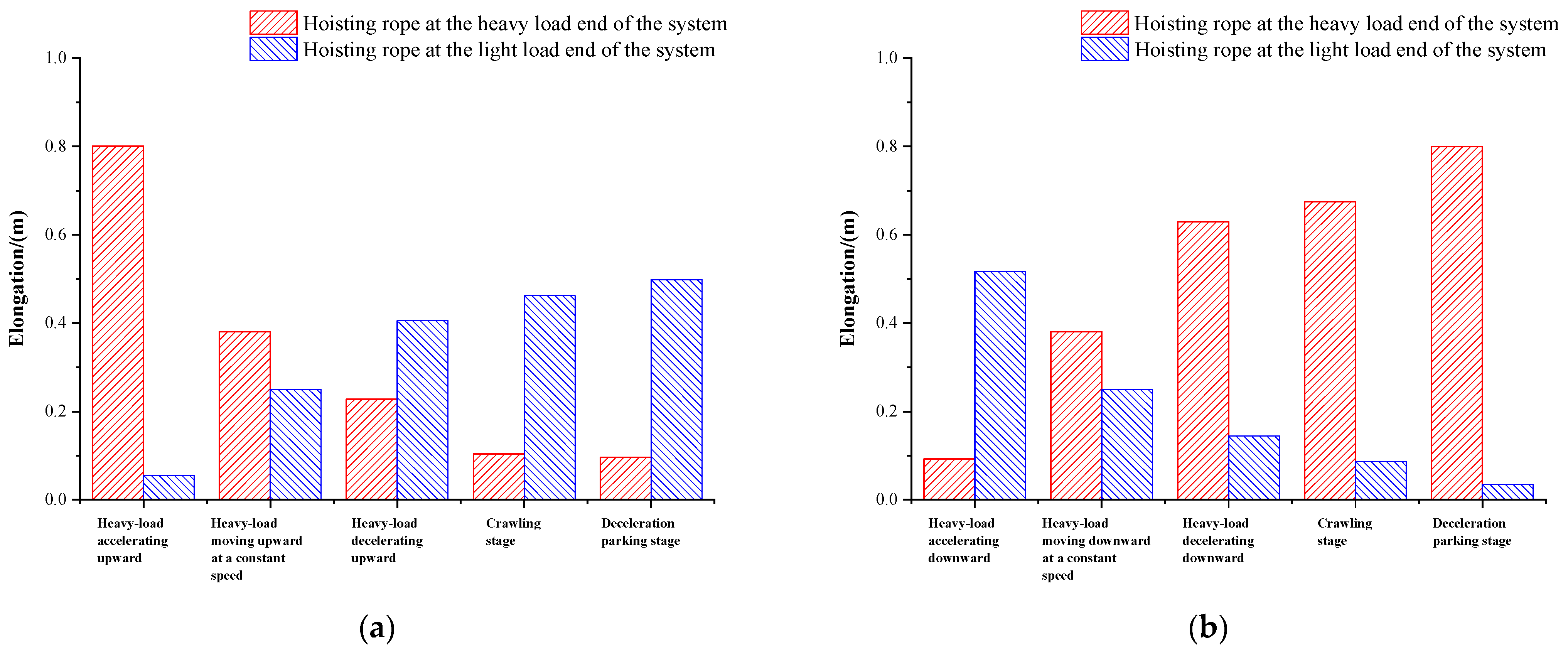
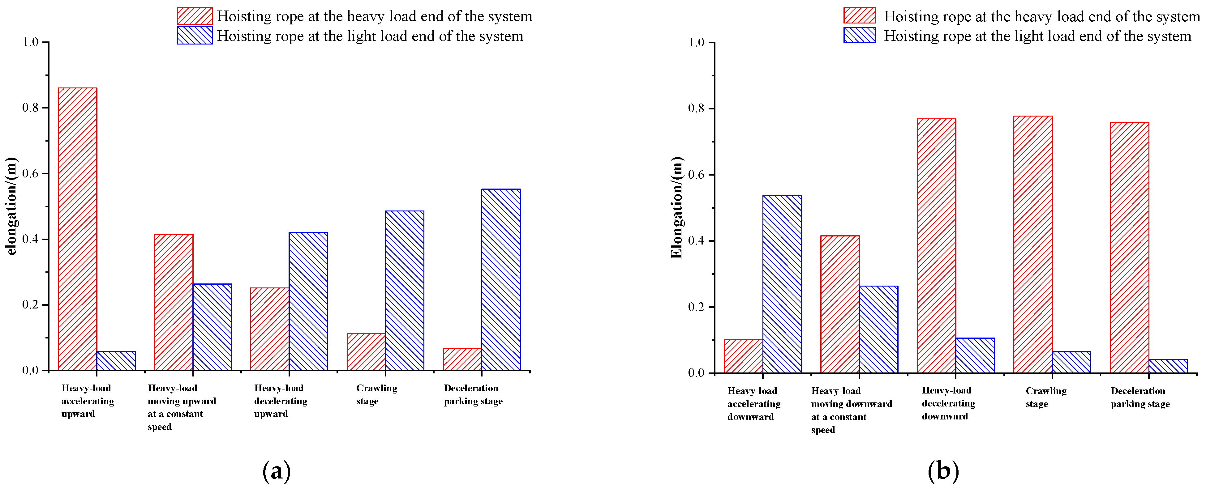
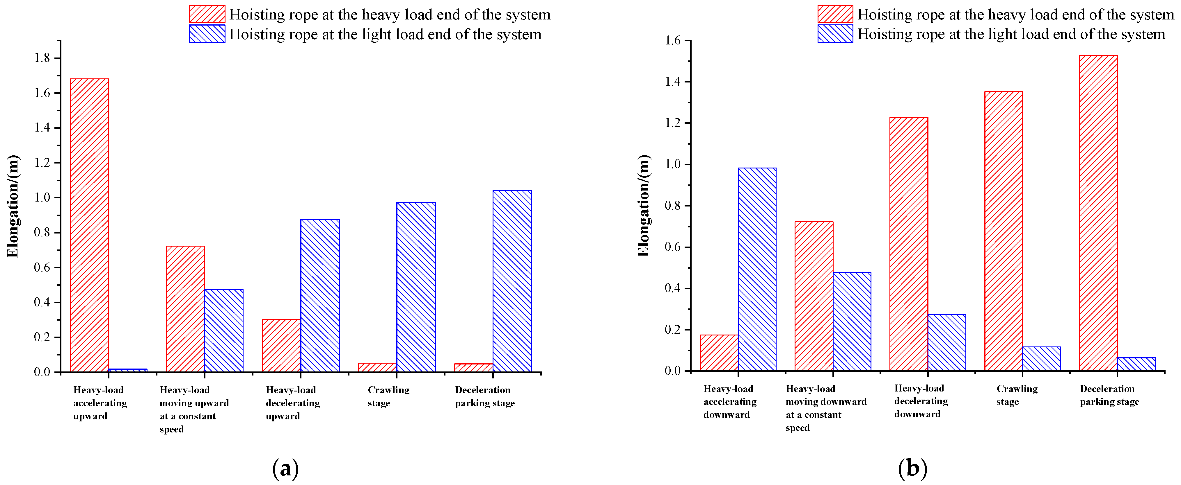
2.4.5. Elongation of Hoisting Wire Rope

The elastic modulus ES of the hoisting wire rope is calculated by Equation (43):
E s = σ z ε
where σz is the nominal stress of rope or strand and ε is the axial strain.
The axial strain ε of the hoisting wire rope is calculated by Equation (44):
ε = Δ L L
where ΔL is the axial elongation of the hoisting wire rope and L is the initial length of the hoisting wire rope.
The nominal stress of rope or strand is calculated by Equation (45):
σ z = F A
where F is the dynamic tension of the hoisting wire rope and A is the cross-sectional area of the hoisting wire rope.
Combining the results from Equations (43)–(45), the elongation of the hoisting rope can be determined as Equation (46):
Δ L = F L A E s
Substituting the calculated results of dynamic tension under different operating conditions into Equation (46) can provide the elongation of the hoisting rope for each specific condition.

3. Design and Calculation Results of Vertical Shaft Multi-Rope Friction Hoisting System

3.1. Operational and Structural Parameters of Typical Hoisting System

Three different types of hoisting wire ropes (round strand, triangular strand, and compacted strand) have been selected for design calculations. Their specific performance parameters are detailed in Table 3. The hoisting system employs a trapezoidal five-stage acceleration curve, as shown in Figure 7, Figure 8 and Figure 9. Taking Figure 7a,b as examples, the hoisting system first undergoes a trapezoidal acceleration process, and the calculation formulas for its acceleration slope can be found in Equations (47)–(51). Subsequently, the system maintains the maximum speed for uniform operation until it reaches the predetermined deceleration position. Next, the system undergoes a trapezoidal deceleration process, and the speed gradually slows down to a crawling speed (v = 0.5 m/s). After maintaining for 3 s in the crawling stage, the system enters the parking stage and finally smoothly reduces the speed to zero. The design of this five-segment acceleration curve aims to enhance the stability and efficiency of the overall operation. The maximum hoisting acceleration/deceleration of three different types of hoisting wire ropes are 0.74 m/s2, 0.61 m/s2, and 0.75 m/s2 respectively. The maximum hoisting speed is 18 m/s and the hoisting distance is 1000 m. The running time of a single hoisting/lowering of three different types of hoisting wire ropes is 85.9 s, 90.7 s, and 85.7 s, respectively. The diameter of the sheave wheel and the spacing of the friction wheel groove are 7000 mm and 425 mm, respectively.
The propagation velocity j of the elastic wave can be calculated by Equation (47):
j = E F P k
where E is the elastic modulus of the hoisting rope, F is the cross-sectional area of the hoisting rope, and Pk is the unit weight of the hoisting rope.
Calculate the ratio of the weight of the first rope to the load at the end of the rope, and construct the transcendental equation, as shown in Equation (48):
α = N 1 P k H c Q d α = λ 1 tan λ 1
where N1 is the number of the hoisting rope, Pk is the unit weight of the hoisting rope, Hc is the overhang height of the first rope, Qd is the load at the end of the rope, and λ1 is the root of the transcendental equation.
Fundamental vibration frequency ω1 can be calculated by Equation (49):
ω 1 = j λ 1 H C H h H R
where j is the propagation speed of elastic wave, Hc is the overhang height of the first rope, λ1 is the root of the transcendental equation, Hh is the height of the tail rope ring, and HR is the height of the container.
The vibration period of elastic wave Tj1 can be calculated by Equation (50):
T j 1 = 2 π ω 1
where, ω1 is the fundamental vibration frequency.
The impact limit value can be calculated by Equation (51):
J 1 = a 1 T j 1
where a1 is the maximum acceleration (deceleration) speed of the hoisting system and Tj1 is the vibration period of the elastic wave.

3.2. Selection Parameters of Hoisting Wire Rope and Balancing Tail Rope

The selection parameters of hoisting wire rope and balancing tail rope are shown in Table 4.

3.3. Static Analysis and Calculation of the Hoisting System

The static calculation results of the hoisting system with different rope selection schemes are shown in Table 5. The maximum static tension at the tangent point of the friction wheel for the three rope selection schemes is consistently observed at the heavy-load end when the right side is the heavy-load end, with values of 2756 kN, 2576 kN, and 2797 kN and the ratio of static tensions is 1.56, 1.62, and 1.55 respectively. The static anti-slip safety coefficient and the pressure ratio between the hoist rope and the friction lining all meet the requirements of the Safety Regulations for Coal Mines. Also, there is little difference in the calculation results when lifting heavy loads on the left and right sides, primarily due to the small vertical distance between the sheave wheels on both sides, resulting in similar calculation results of initial overhang height on both sides of the hoist rope and tail rope.

3.4. Dynamic Analysis and Calculation of the Hoisting System

3.4.1. Equivalent Mass and Limit Acceleration/Deceleration

Table 6 shows the total equivalent mass and limit acceleration/deceleration of the hoisting system for three rope selection schemes. The total equivalent mass of the hoisting system for different rope selection schemes is 736 t, 696 t, and 744 t. The maximum equivalent masses and the minimum equivalent masses are similar when lifting heavy loads on the left and right sides, respectively. The maximum accelerations/decelerations of the hoisting system are 0.74 m/s2, 0.61 m/s2, and 0.75 m/s2, respectively.

3.4.2. Dynamic Tension and Dynamic Anti-Slip Safety Coefficient of Hoisting Rope

The dynamic tension of the hoisting rope at different stages in different rope selection schemes is shown in Figure 10, Figure 11 and Figure 12. The dynamic anti-slip safety coefficients of the hoisting rope at different stages in different rope selection schemes is shown in Figure 13, Figure 14 and Figure 15. In Figure 10, 1 represents the stage of heavy load accelerating upward, 2 represents the stage of heavy load moving upward at a constant speed, 3 represents the stage of heavy load decelerating upward, 4 represents the stage of crawling, 5 represents the stage of parking, 6 represents the stage of heavy load accelerating downward, 7 represents the stage of heavy load moving downward at a constant speed, 8 represents the stage of heavy load decelerating downward, 9 represents the stage of crawling, 10 represents the stage of parking.
As can be seen from Figure 10, Figure 11 and Figure 12, the changing trends of the dynamic tension exerted on the hoisting wire rope at the heavy-load end in different stages for different rope selection schemes are basically consistent with the changing trend of the acceleration control curve, both exhibiting a five-stage variation. This indicates that the dynamic tension on the hoisting wire rope at the heavy-load end is positively correlated with the acceleration. The greater the acceleration, the greater the dynamic tension it undergoes. The dynamic tension of the hoisting wire rope at the light-load end has an opposite changing trend to the acceleration control curve. This is because the movement direction of the light-load end is opposite to that of the heavy-load end, resulting in an opposite changing trend of the dynamic tension. Further observations reveal that the differences in dynamic tension on both sides of pulley for three rope selection schemes are the greatest in the heavy-load accelerated hoisting stage and the heavy-load decelerated lowering stage, which are 1556.3 kN, 1448.9 kN, and 1576 kN respectively. Among them, the second scheme that adopts the fiber core wire rope has the smallest tension difference. This is attributed to the relatively light unit weight of the fiber core wire rope, which has a relatively small influence on the tension difference.
The anti-slip safety was evaluated based on the dynamic tension (Figure 13, Figure 14 and Figure 15). The dynamic anti-slip safety coefficients in each stage for three rope selection schemes all meet the minimum requirement of 1.25 stipulated in the Safety Regulations for Metal and Nonmetal Mines. It is worth noting that in the heavy-load accelerated hoisting and heavy-load decelerated lowering stages, although the dynamic anti-slip safety coefficient meets the specification standard, the anti-slip safety coefficient is relatively low due to the large tension difference on both sides of the pulley, increasing the risk of slippage. Conversely, in the heavy-load decelerated hoisting and heavy-load accelerated lowering stages, due to the opposite changing trends of the dynamic tension on both sides of the pulley, the tension difference decreases, and the dynamic anti-slip safety coefficient significantly increases to the maximum value, reducing the possibility of slippage.
Through comparison, it is found that although the second rope selection scheme performs exceptionally well in reducing the tension difference, its dynamic anti-slip safety coefficient is not significantly increased. Instead, it is similar to other schemes. This is because the dynamic anti-slip safety coefficient of 1.25 is selected when calculating the limit acceleration/deceleration. Therefore, regardless of the calculation method, the dynamic anti-slip safety coefficient under this acceleration will be greater than 1.25. Hence, future research should consider the comprehensive influence of multiple parameters such as speed, acceleration, and hoisting load on the anti-slip safety performance more comprehensively to provide more accurate evaluation and optimization strategies.

3.4.3. Elongation of Hoisting Wire Rope

The elongation of the steel wire rope at the connection between container and rope at different stages in different rope selection schemes is shown in Figure 16, Figure 17 and Figure 18.
As can be seen from Figure 16a, Figure 17a and Figure 18a, in the heavy-load lifting phase, the elongation of the hoisting ropes at the heavy-load end presents a downward trend, and the variation ranges are 0.1 mm–0.8 mm, 0.07 mm–0.86 mm, and 0.05 mm–1.68 mm, respectively. The reason is that with the lifting of heavy-load, the overhang height and dynamic tension of the hoisting rope at the heavy-load end decrease continuously, and the elongation of the rope decreases when the elastic modulus and cross-sectional area of rope are unchanged. On the contrary, the elongation of the hoisting rope at the light-load end continues to increase, and their variation ranges are 0.05 mm–0.5 mm, 0.06 mm–0.55 mm, 0.02 mm–1.04 mm, respectively.
As can be seen from Figure 16b, Figure 17b and Figure 18b, in the heavy-load lowering phase, the elongation of the hoisting ropes at the heavy-load end presents an upward trend, and the variation ranges are 0.09 mm–0.8 mm, 0.1 mm–0.76 mm, and 0.18 mm–1.53 mm, respectively. The reason is that with the lowering of heavy-load, the overhang height and dynamic tension of the hoisting rope at the heavy-load end increase continuously, and the elongation of the rope increases when the elastic modulus and cross-sectional area of rope are unchanged. On the contrary, the elongation of the hoisting rope at the light-load end continues to decrease, and the variation ranges are 0.03 mm–0.52 mm, 0.04 mm–0.54 mm, 0.07 mm–0.98 mm, respectively.
In addition, it is found that the elongation of the compacted strand wire rope is much larger than the other two kinds of steel wire rope, because its elastic modulus is smaller and it deforms easily.

4. Conclusions

In this paper, a design method for a multi-rope friction hoisting system of a vertical shaft gravity energy storage system was proposed. A complete set of calculation and selection theories about the structural parameters, the hoisting rope and the tail rope, and static and dynamic analysis of the hoisting system were proposed. In addition, the parameter calculations of the hoisting rope, balance rope, and friction wheel of the friction hoisting system under typical lifting conditions were carried out. The static and dynamic anti-slip capabilities of the friction hoisting system under the typical condition were explored. The design scheme has definite guiding significance for the design of a hoisting system for a gravity energy storage system.
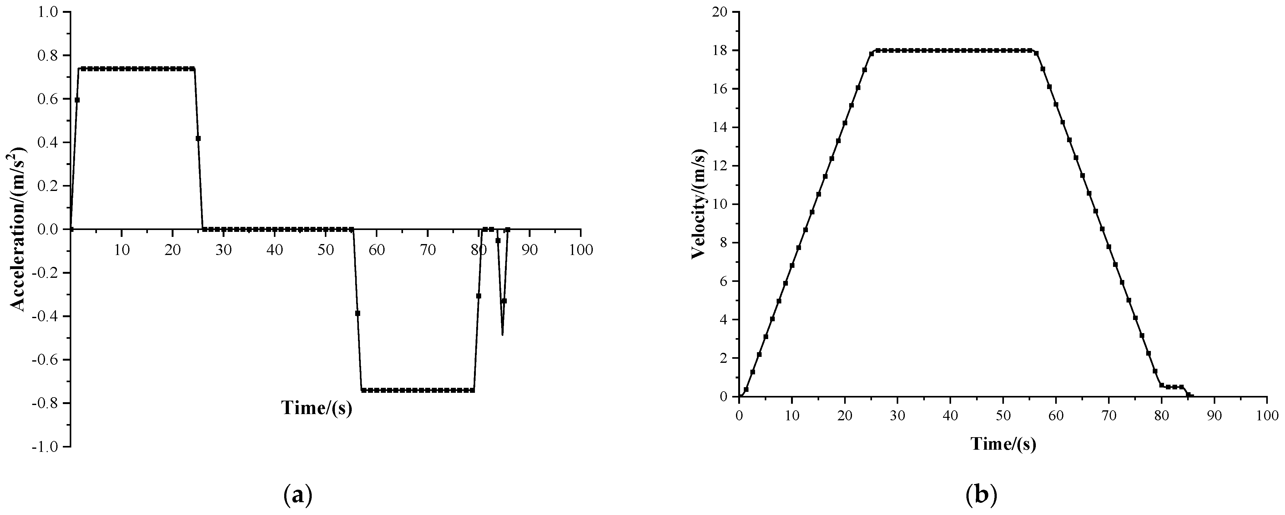
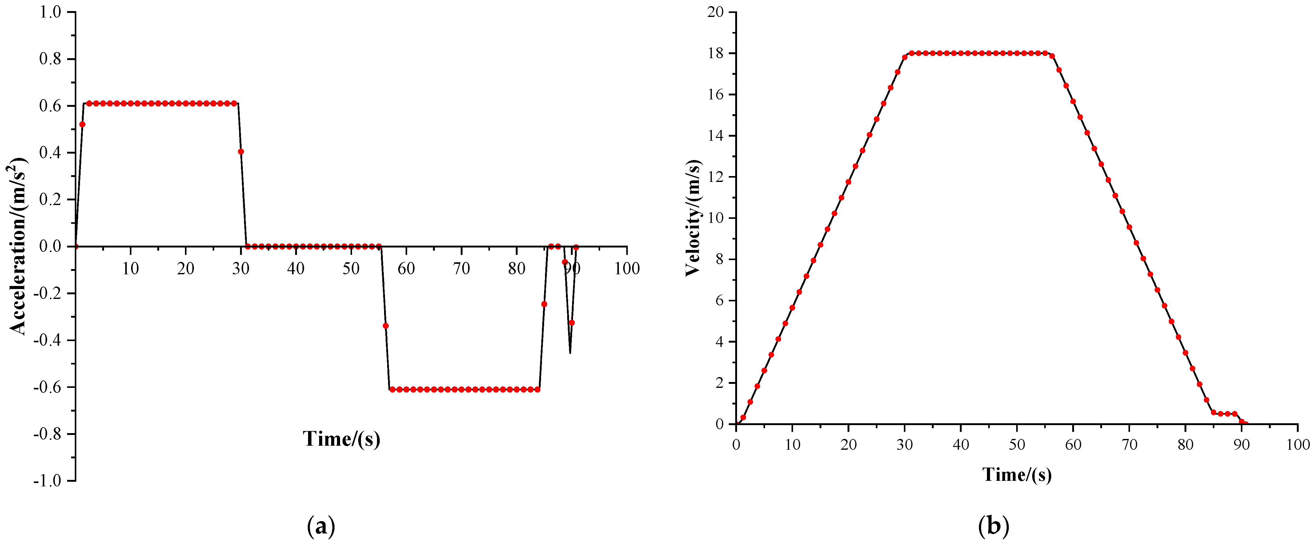
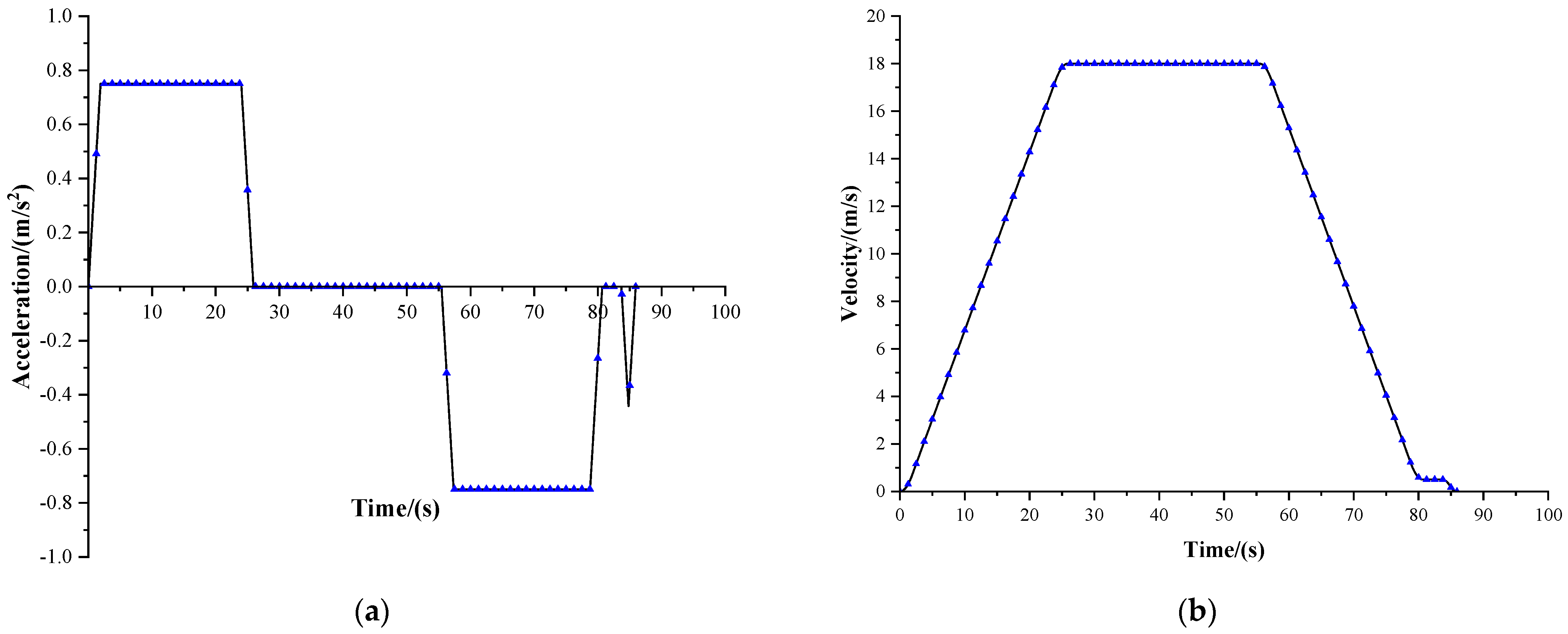
  • The results show that the maximum acceleration/deceleration speed of the compacted strand steel wire rope is 0.75 m/s2, and the time of lifting/lowering is the shortest, which is 85.7 s. The maximum acceleration/deceleration speed of the triangular strand steel wire rope is the smallest, which is 0.61 m/s2, and the time of lifting/lowering is the longest, which is 90.7 s.
  • The maximum static tension at the tangent point of the friction wheel in different rope selection schemes was all at the heavy-load end when the right side was the heavy-load end, which was 2756 kN, 2576 kN, and 2797 kN, respectively, and the ratio of static tension was 1.56, 1.62, and 1.55, respectively. The static anti-slip safety coefficient between the hoisting rope and friction lining and the specific pressure between the hoisting rope and friction lining meet the requirements of the Safety Regulations for Coal Mines.
  • The dynamic tension of the hoisting rope at the heavy-load end is positively correlated with the acceleration, and the maximum values are at the acceleration lifting stage and the deceleration lowering stage of the heavy load: 3252.8 kN, 3000 kN, and 3302.6 kN, respectively. At this time, the dynamic tension of the hoisting rope at the light-load end is the lowest: 1696.5 kN, 1551.1 kN, and 1726.6 kN, respectively. The minimum values appear at the deceleration lifting stage and the acceleration lowering stage of the heavy load: 2573.7 kN, 2400.6 kN, and 2614.2 kN, respectively. At this time, the dynamic tension of the hoisting rope at light-load end is the largest: 2132.8 kN, 1900.6 kN, and 2168.1 kN, respectively.
  • The dynamic anti-slip safety coefficient of the hoisting system in the different rope selection schemes is greater than the minimum value of 1.25 stipulated in the Safety Regulations for Metal and Non-Metal Mines. The elastic modulus of the hoisting rope has a great influence on the elongation of the wire rope. Considering that the elongation of the wire rope will cause the cages on both sides to fail to reach the designated parking position at the same time, it is recommended that hoisting ropes with large elastic moduli be used.
In future study, we will continue to explore the transmission reliability of the hoisting system under different environments and operating parameters and investigate the impact of different lifting parameters (lifting height, lifting speed, and lifting capacity) on the energy storage efficiency of the gravity energy storage system. Finally, we will comprehensively consider the energy storage efficiency, lifting efficiency, and operating reliability of the gravity energy storage system, and come up with an optimal hoisting scheme.

Author Contributions

Conceptualization, Q.S. and D.W.; methodology, Q.S., D.W., X.Z., Y.G. and H.W.; formal analysis, Q.S., D.W., X.Z., Y.G. and H.W.; investigation, Z.X., Q.D., H.Z., B.W. and C.L.; data curation, Z.X., Q.D. and H.Z.; writing—original draft preparation, Q.S., D.W. and Y.G.; writing—review and editing, D.W., Z.X., Q.D. and H.Z.; supervision, Q.S., D.W., X.Z., Y.G. and H.W.; project administration, D.W.; funding acquisition, D.W. All authors have read and agreed to the published version of the manuscript.

Funding

The research was funded by the Special Research on Mechanical and Electrical Control Systems—“Gravity energy storage based on vertical shaft”, funded by North China Power Engineering Co., Ltd. of China Power Engineering Consulting Group. The authors also wish to thank Top-Notch Academic Programs Project of Jiangsu Higher Education Institutions (TAPP) and a project funded by the Priority Academic Program Development of Jiangsu Higher Education Institutions (PAPD).

Institutional Review Board Statement

Not applicable.

Informed Consent Statement

Not applicable.

Data Availability Statement

The data presented in this study are available on request from the corresponding author. The data are not publicly available due to privacy.

Conflicts of Interest

Authors Qinpeng Shi, Xiaochao Zeng and Hao Wang were employed by North China Power Engineering Co. Ltd. of China Power Engineering Consulting Group. The remaining authors declare that the research was conducted in the absence of any commercial or financial relationships that could be construed as a potential conflict of interest.

References

  1. Tang, B.; Li, R. Impact of reduced renewable energy costs on carbon peak and carbon neutrality of power industry. Enterp. Econ. 2021, 40, 53–63. [Google Scholar]
  2. Wu, J.; Tang, G.; Wang, R.; Yanwei, S. Multi-objective optimization for China’s power carbon emission reduction by 2035. J. Therm. Sci. 2019, 28, 184–194. [Google Scholar] [CrossRef]
  3. Ding, J.; Xu, Y.; Wang, Z.; Hu, S.; Chen, H. Estimating the economics of electrical energy storage based on different policies in China. J. Therm. Sci. 2020, 29, 352–364. [Google Scholar] [CrossRef]
  4. Liu, S.; Song, L.; Dai, B.; VICTOR, N. Analysis on optimal dispatching of integrated energy system with additional carbon tax. J. Eng. Thermophys. 2022, 43, 1790–1800. [Google Scholar]
  5. Husin, H.; Zaki, M. A Critical Review of the Integration of Renewable Energy Sources with Various Technologies. Prot. Control. Mod. Power Syst. 2021, 6, 1–18. [Google Scholar]
  6. Li, J.; Zhang, L.; Zhang, B.; Tang, W. Coordinated planning for flexible interconnection and energy storage system in low-voltage distribution networks to improve the accommodation capacity of photovoltaic. Glob. Energy Interconnect. 2023, 6, 700–713. [Google Scholar] [CrossRef]
  7. Tong, W.; Lu, Z.; Chen, W.; Han, M.; Zhao, G.; Wang, X.; Deng, Z. Solid gravity energy storage: A review. J. Energy Storage 2022, 53, 105226. [Google Scholar] [CrossRef]
  8. Triebel, C.; Reincke-Collon, C.; Berninger, U.; Tröndle, T. Method and Apparatus for Operating an Electrical Energy Storage System. U.S. Patent 11,025,063, 1 June 2021. [Google Scholar]
  9. Zhang, Z.; Wu, A.; Zhang, H. Gravity Energy Storage System Depending on Coal Mine. Chinese Patent 209,676,010U, 22 November 2019. [Google Scholar]
  10. Song, L.; Dong, B.; Wang, D.; Wang, S.; Zhu, L.; Wu, Y. Gravity Energy Storage System of Hoisting and Transporting System Based on Mine Vertical Shaft. Chinese Patent 109,665,430A, 23 April 2019. [Google Scholar]
  11. Pedretti, A.; Gross, W. Energy Storage System and Method. U.S. Patent 20,200,028,379, 23 January 2020. [Google Scholar]
  12. O’Grady, C. Gravity powers batteries for renewable energy. Science 2021, 372, 446. [Google Scholar] [CrossRef]
  13. Chaves, E. Modular Gravitational Energy Storage Systems. U.S. Patent 20,210,336,478, 28 October 2021. [Google Scholar]
  14. Qiu, Q.; Xiao, L.; Zhang, J.; Wang, S.; Xia, X.; Tang, W.; Zhang, D.; Guo, W.; Xu, X. Gravity Energy Storage System Based on Vertical Shaft and Roadway. Chinese Patent 113,460,841A, 1 October 2021. [Google Scholar]
  15. Qiu, Q.; Xiao, L.; Nie, Z.; Zhang, J.; Teng, Y.; Wang, S.; Zhao, Y.; Zhou, W. Gravity Energy Storage System Based on Efficient Lifting and Transferring of Multiple Heavy Objects. Chinese Patent 114,151,296A, 8 March 2022. [Google Scholar]
  16. Qiu, Q.; Zhao, Y.; Xiao, L.; Nie, Z.; Zhang, J.; Teng, Y.; Wang, S.; Luo, X.; Zhou, W. Automatic Connection and Parking System for Multi-Weight Gravity Energy Storage. Chinese Patent 114,899,951A, 12 August 2022. [Google Scholar]
  17. Xiao, L.; Zhang, J.; Nie, Z.; Wang, Z.; Wang, S.; Tang, W.; Yan, C.; Li, X.; Xia, X.; Qiu, Q.; et al. Underground energy storage project engineering. Adv. Technol. Electr. Eng. Energy 2022, 41, 1–9. (In Chinese) [Google Scholar]
  18. Emergency Management Department. China’s Safety Regulations for Coal Mines; Emergency Management Department: Beijing, China, 2016.
  19. AQ 1014-2005; Safety Inspections-Testing Specifications of In-Service Friction Hoist System for Coal Mines. State Administration of Work Safety: Beijing, China, 2005.
  20. GB/T 10599-2023; Multi-Rope Friction Hoist. State Administration for Market Regulation, Standardization Administration of China: Beijing, China, 2023.
  21. GB/T 8918-2006; Steel Wire Ropes for Important Purposes. General Administration of Quality Supervision, Inspection and Quarantine of the People’s Republic of China: Beijing, China, 2006.
  22. Li, Y.; Co, Z. Basic Theory of Mine Hoisting System; Coal Industry Press: Beijing, China, 2013. [Google Scholar]
  23. YB/T 5359-2020; Compacted Strand Ropes. Ministry of Industry and Information Technology of the People’s Republic of China: Beijing, China, 2020.
  24. Wang, S. Selection and damage analysis of balance rope of multi rope friction elevator in coal mine vertical shaft. Technol. Enterp. 2013, 3, 273. (In Chinese) [Google Scholar]
  25. GB/T 20119-2023; Steel Wire Ropes for Balance. State Administration for Market Regulation, Standardization Administration of China: Beijing, China, 2023.
  26. GB 16423-2020; Safety Regulation for Metal and Nonmetal Mines. State Administration for Market Regulation, Standardization Administration of China: Beijing, China, 2020.
  27. Ding, S. Study on measuring method of equivalent mass of mine elevating system. Coal Mine Mach. 2017, 38, 53–55. (In Chinese) [Google Scholar]
Figure 1. Working principle of gravity energy storage system. 1—Ground; 2—derrick; 3—sheave wheel; 4—hoisting rope; 5—canister road; 6—lifting container; 7—balance rope; 8—friction wheel; 9—machine-side converter; 10—grid-side converter; 11—transformer; 12—power grid.
Applsci 14 07556 g001
Figure 2. Floor-standing multi-rope friction hoisting system with double cages. 1—Left cage; 2—hoisting rope; 3—upper sheave wheel; 4—lower sheave wheel; 5—friction wheel; 6—right cage; 7—balance rope.
Applsci 14 07556 g002
Figure 3. Schematic diagram of hoisting system of vertical shaft gravity energy storage system.
Applsci 14 07556 g003
Figure 4. Energy storage process of the shaft gravity energy storage system: (a) heavy load on the left side accelerating upward, light load on the right side accelerating downward, (b) heavy load on the left side moving upward at a constant speed, light load on the right side moving downward at a constant speed, (c) heavy load on the left side decelerating upward, light load on the right side decelerating downward, (d) heavy load on the right side accelerating upward, light load on the left side accelerating downward, (e) heavy load on the right side moving upward at a constant speed, light load on the left side moving downward at a constant speed, (f) heavy load on the right side decelerating upward, light load on the left side decelerating downward.
Applsci 14 07556 g004aApplsci 14 07556 g004b
Figure 5. Energy release process of the shaft gravity energy storage system: (a) heavy load on the left side accelerating downward, light load on the right side accelerating upward, (b) heavy load on the left side moving downward at a constant speed, light load on the right side moving upward at a constant speed, (c) heavy load on the left side decelerating downward, light load on the right side decelerating upward, (d) heavy load on the right side accelerating downward, light load on the left side accelerating upward, (e) heavy load on the right side moving downward at a constant speed, light load on the left side moving upward at a constant speed, (f) heavy load on the right side decelerating downward, light load on the left side decelerating upward.
Applsci 14 07556 g005
Figure 6. Force situation between rope and sheave wheels and friction wheel.
Applsci 14 07556 g006
Figure 7. Acceleration and velocity control curve of round strand wire rope: (a) acceleration control curve during the heavy-load lifting phase, (b) velocity control curve during the heavy-load lifting phase.
Applsci 14 07556 g007
Figure 8. Acceleration and velocity control curves of triangle strand wire rope: (a) acceleration control curve during the heavy-load lifting phase, (b) velocity control curve during the heavy-load lifting phase.
Applsci 14 07556 g008
Figure 9. Acceleration and velocity control curve of compacted strand wire rope: (a) acceleration control curve during the heavy-load lifting phase, (b) velocity control curve during the heavy-load lifting phase.
Applsci 14 07556 g009
Figure 10. Dynamic tension of round strand wire rope at different stages: (a) heavy-load lifting phase, (b) heavy-load lowering phase.
Applsci 14 07556 g010
Figure 11. Dynamic tension of triangle strand wire rope at different stages: (a) heavy-load lifting phase, (b) heavy-load lowering phase.
Applsci 14 07556 g011
Figure 12. Dynamic tension of compacted strand wire rope at different stages: (a) heavy-load lifting phase, (b) heavy-load lowering phase.
Applsci 14 07556 g012
Figure 13. Dynamic anti-slip safety coefficients of round strand wire rope at different stages: (a) heavy-load lifting phase, (b) heavy-load lowering phase.
Applsci 14 07556 g013
Figure 14. Dynamic anti-slip safety coefficients of triangle strand wire rope at different stages: (a) heavy-load lifting phase, (b) heavy-load lowering phase.
Applsci 14 07556 g014
Figure 15. Dynamic anti-slip safety coefficients of compacted strand wire rope at different stages: (a) heavy-load lifting phase, (b) heavy-load lowering phase.
Applsci 14 07556 g015
Figure 16. Elongation of round strand wire rope at different stages: (a) heavy-load lifting phase, (b) heavy-load lowering phase.
Applsci 14 07556 g016
Figure 17. Elongation of triangle strand wire rope at different stages: (a) heavy-load lifting phase, (b) heavy-load lowering phase.
Applsci 14 07556 g017
Figure 18. Elongation of compacted strand wire rope at different stages: (a) heavy-load lifting phase, (b) heavy-load lowering phase.
Applsci 14 07556 g018
Table 1. Requirements for the ratio of the minimum diameter of the sheave wheel, drum, friction wheel, and guide wheel to the diameter of the steel wire rope.
Use ClassificationMinimum Ratio
Friction wheel and the sheave wheel of the floor-standing friction hoisting system, and the friction wheel of the tower friction hoisting system with a wrapping angle greater than 180°Aboveground90
Underground80
Friction wheel of the tower friction hoisting system with a wrapping angle of 180°Aboveground80
Underground70
Guide wheel of friction hoisting system80
Drum and the sheave wheel with a wrapping angle greater than 90° of the ground winding hoisting system80
Sheave wheel with a wrapping angle smaller than 90° of the ground winding hoisting system60
Drum of the underground winding hoist and drilling hoist, the leading wheel and tail guide wheel and the sheave wheel with a wrapping angle greater than 90° of the underground overhead passenger device60
Sheave wheel with a wrapping angle smaller than 90° of the underground winding hoist, the drilling hoist and the underground overhead passenger device40
Table 2. Minimum safety coefficient of wire rope under different working conditions.
Service ClassificationMinimum Safety Coefficient
Single rope winding hoisting systemSpecially designed for hoisting personnel9
Hoist personnel and materialsHoist personnel9
Mixed hoist9
Hoist materials7.5
Specially designed for hoisting materials6.5
Friction wheel hoisting systemSpecially designed for hoisting personnel9.2–0.0005H
Hoist personnel and materialsHoist personnel9.2–0.0005H
Mixed hoist9.2–0.0005H
Hoist materials8.2–0.0005H
Specially designed for hoisting materials7.2–0.0005H
Cage guide rope, anti-collision rope and hoisting rope6
Table 3. Operational and structural parameters of typical hoisting system.
ParametersHoisting Rope
Round StrandTriangular StrandCompacted Strand
Operational ParametersMaximum operating speed, vmax/(m/s)18
Hoisting acceleration/deceleration, a/(m/s2)0.740.610.75
Operating time, T/(s)85.990.785.7
Structural parametersUpper rope length, Ls/(m)62.2
Lower rope length, Lx/(m)49.49
Upper rope angle, βs/(°)53.04
Lower rope angle, βx/(°)54.39
Wrapping angle of hoisting rope on friction lining, α/(rad)181.35
Sheave wheel diameter ratioThe calculation result of Equation (6)/(mm)≥5580≥5220≥5400
The calculation result of Equation (7)/(mm)≥3936≥3804≥4400
Friction wheel-groove spacing/(mm)425
Table 4. Selection design of hoisting rope and balancing tail rope.
Design ParameterSelection Scheme
Selection design of hoisting ropeStructureRound strandTriangular strandCompacted strand
6 × 37S + IWR6V × 37 + FC35W × K19S
Number of hoisting rope, n1666
Minimum safety coefficient, ma specified by Regulations6.76.76.7
Minimum nominal diameter, dmin/(mm)6067.254
Actual selected nominal diameter, d1/(mm)625860
Weightlift factor, K10.4180.4050.48
Minimum breaking force factor, K20.3560.360.395
Conversion factor, K31.3211.1771.287
Nominal tensile strength, R0/(MPa)177017701960
Unit weight, pk/(kg/m)16.613.617.3
Cross-sectional area, A/(mm2)301926422827
Elastic modulus, ES/(GPa)210206120
Minimum breaking force, F0/(kN)242021402787
Calculated minimum breaking force, F0/(kN)242221442787
Safety coefficient, m (Calculated value)6.95.87.6
Load ratio = Effective lifting load/Rope weight1.541.881.48
Selection design of balance tail ropeNumber of tail rope, n2443
Unit weight, qk/(kg/m)24.920.434.2
Elastic modulus, Ew/(GPa)120120120
Note: For the selection of the 6V × 37 + FC type hoisting rope, since this model does not have a large diameter of 67.2 mm, the largest diameter available in the selection table, 58 mm, is chosen as the calculation case.
Table 5. Static calculations of different rope selection schemes in hoisting system.
Heavy-Load End PositionCalculation ParameterRound StrandTriangular StrandCompacted Strand
Left cage as heavy-load endStatic tension at friction wheel cut point at heavy-load end, Fj1/(kN)275225732793
Static tension at friction wheel cut point at light-load end, Fj2/(kN)177615961805
Ratio of static tension, Fj1/Fj21.551.611.54
Static anti-slip safety coefficient of the rope-lining, δ2.191.972.20
Pressure ratio of the rope-lining, P/(MPa)1.741.711.82
Right cage as heavy-load endStatic tension at friction wheel cut point at heavy-load end, Fj3/(kN)275625762797
Static tension at friction wheel cut point at light-load end, Fj4/(kN)177115931802
Ratio of static tension, Fj1/Fj21.561.621.55
Static anti-slip safety coefficient of the rope-lining, δ2.171.962.18
Pressure ratio of the rope-lining, P/(MPa)1.741.711.82
Note: According to the Safety Regulations for Coal Mines, the static anti-slip safety coefficient of wire ropes in multi-rope friction hoisting systems must not be less than 1.75. Additionally, the ratio pressure between the wire rope and the friction lining should not exceed 2 MPa.
Table 6. Dynamic calculations of hoisting system with different rope selection schemes (displacement mass and limiting acceleration/deceleration calculation).
ParametersPosition of the Heavy-Load EndCalculation ParameterHoisting Rope
Round StrandTriangular StrandCompacted Strand
Displacement mass of hoisting systemLeft cageMaximum displacement mass at heavy-load end, m1/(t)332312335
Minimum displacement mass at light-load end, m2/(t)229210234
Right cageMaximum displacement mass at heavy-load end, m3/(t)329310334
Minimum displacement mass at light-load end, m4/(t)232212235
Total displacement mass of hoisting system, ∑M/(t)736696744
Limiting acceleration/deceleration of hoisting systemLeft cageLimiting acceleration/deceleration, amax/(m/s2)0.940.780.95
Right cage0.930.760.94
Actual acceleration/deceleration value = 0.8·Min [Left, Right amax]0.740.610.75
Disclaimer/Publisher’s Note: The statements, opinions and data contained in all publications are solely those of the individual author(s) and contributor(s) and not of MDPI and/or the editor(s). MDPI and/or the editor(s) disclaim responsibility for any injury to people or property resulting from any ideas, methods, instructions or products referred to in the content.

