
Methodology and Monitoring of the Strengthening and Upgrading of a Four-Story Building with an Open Ground Floor in a Seismic Region


Abstract
:1. Introduction
2. Research Aims, Scope, and Novelty
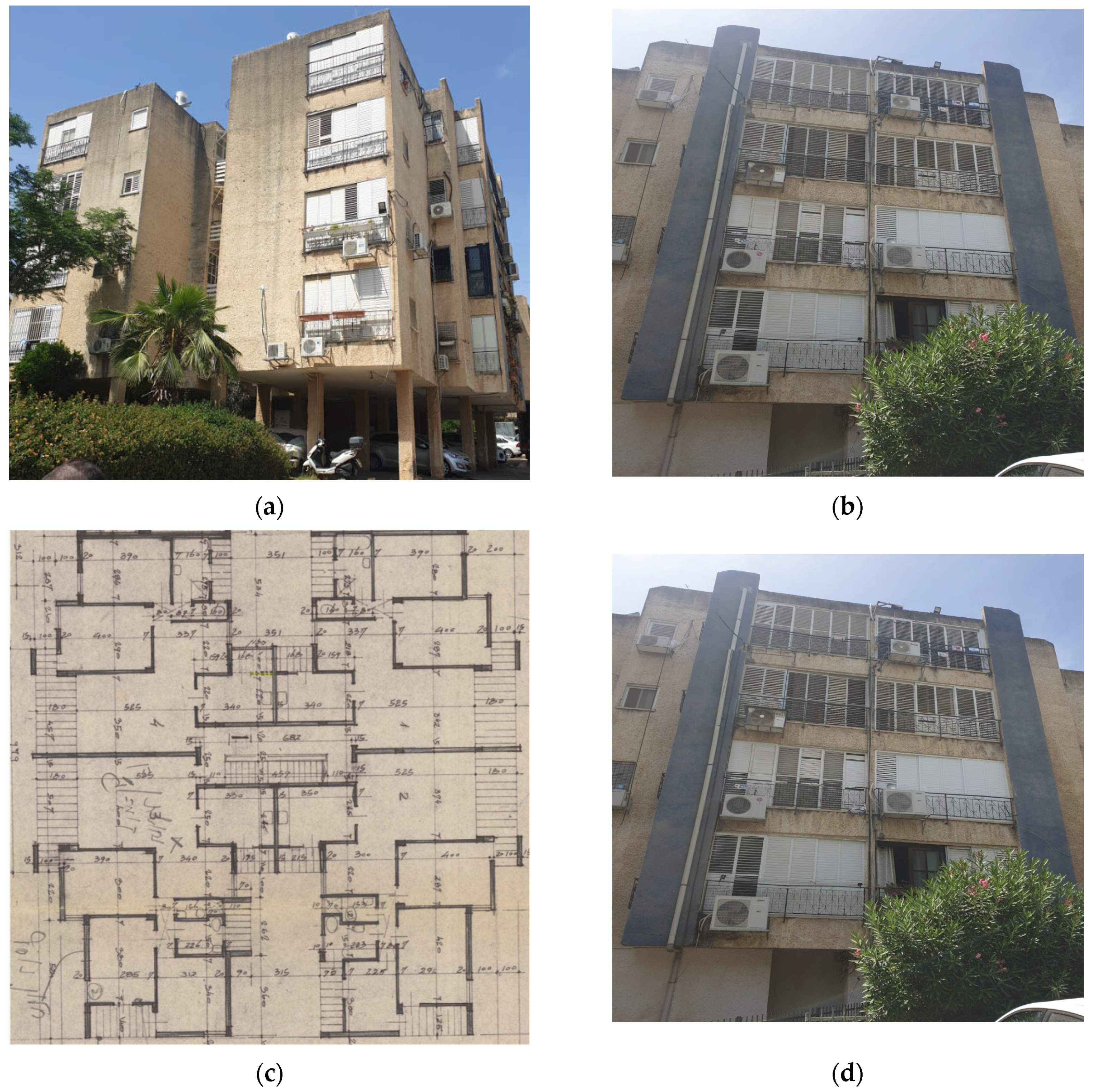
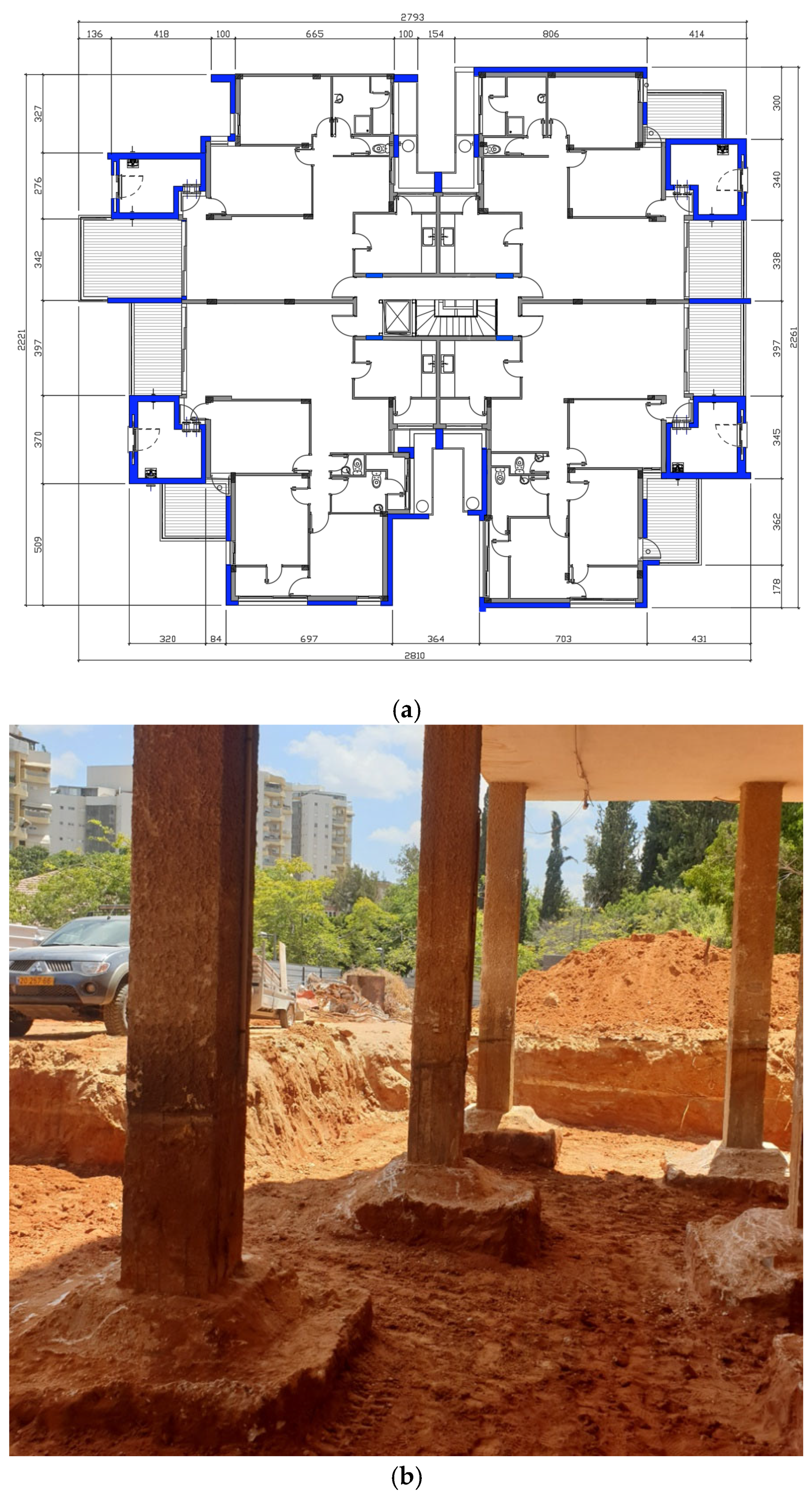
3. Description of the Investigated Building
4. Research Methodology
- -
- Initial 3D linear elastic analysis under vertical static loads only;
- -
- -
5. Measurement Equipment and Testing Setup
5.1. Four-Dimensional Sensor
5.2. 3D Sensor
5.3. Software for Dynamic Data Processing
5.4. Analysis of Sensor Efficiency
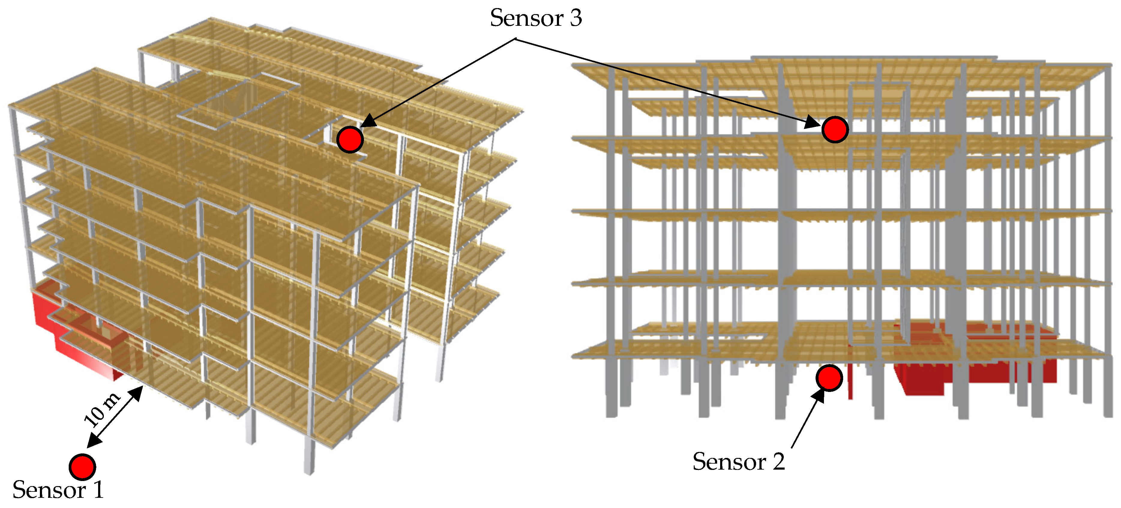
5.5. Sensor Location in the Building
6. Experimental and Numerical Evaluation of the Building’s Dynamic Characteristics in Each Stage of Its Strengthening and Upgrading
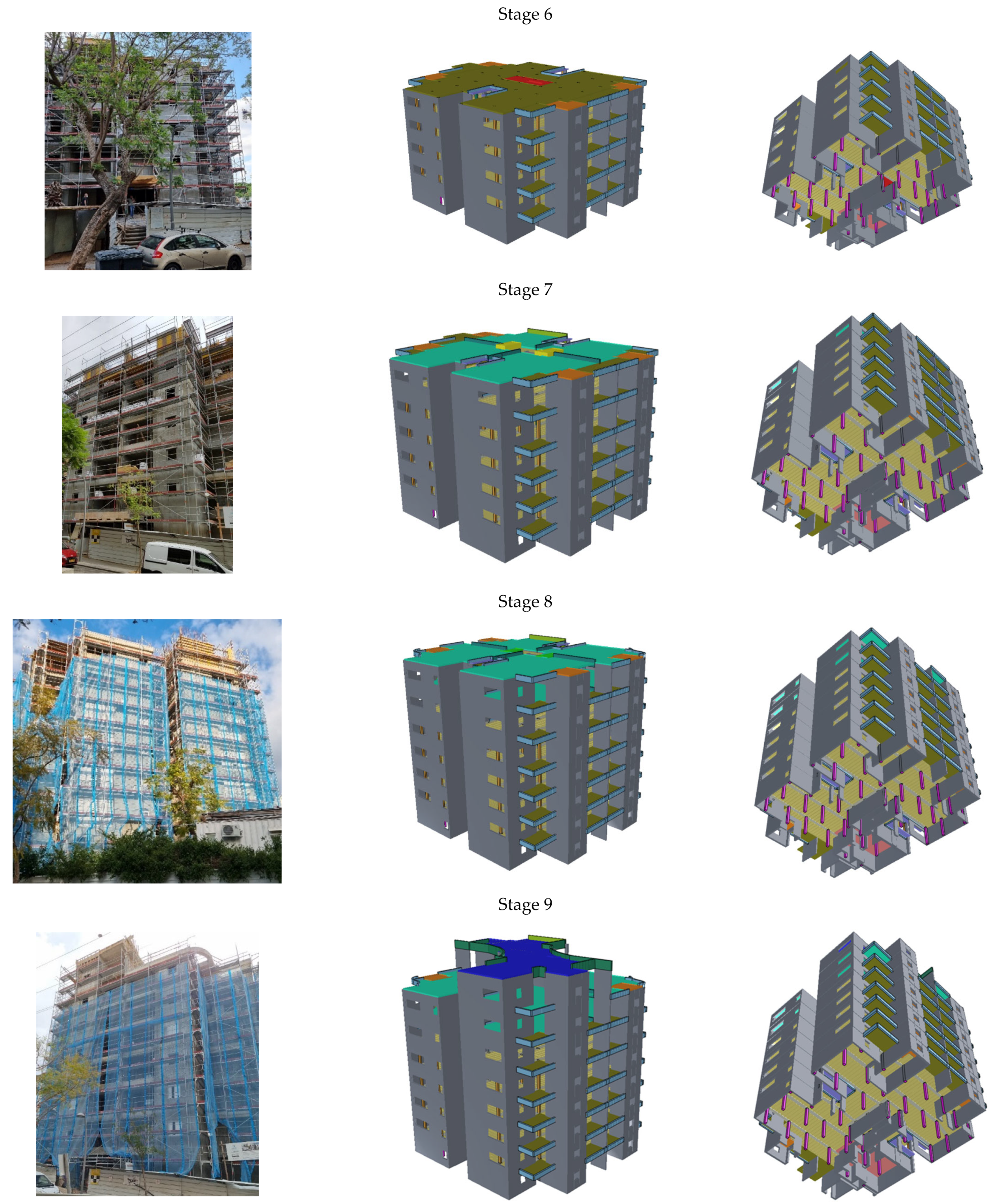
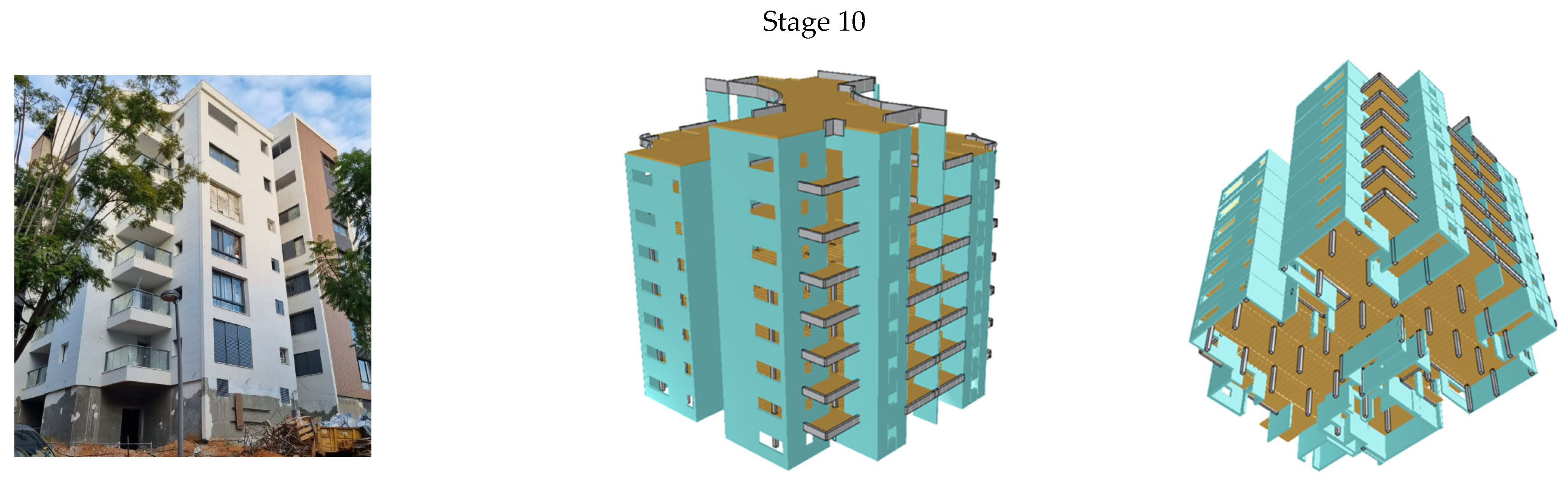
6.1. The Building Strengthening and Upgrading Stages
- -
- Stage 0—the existing building before beginning the work at the site: the building was modeled according to its state (as is) following the guidelines of the modern code [1];
- -
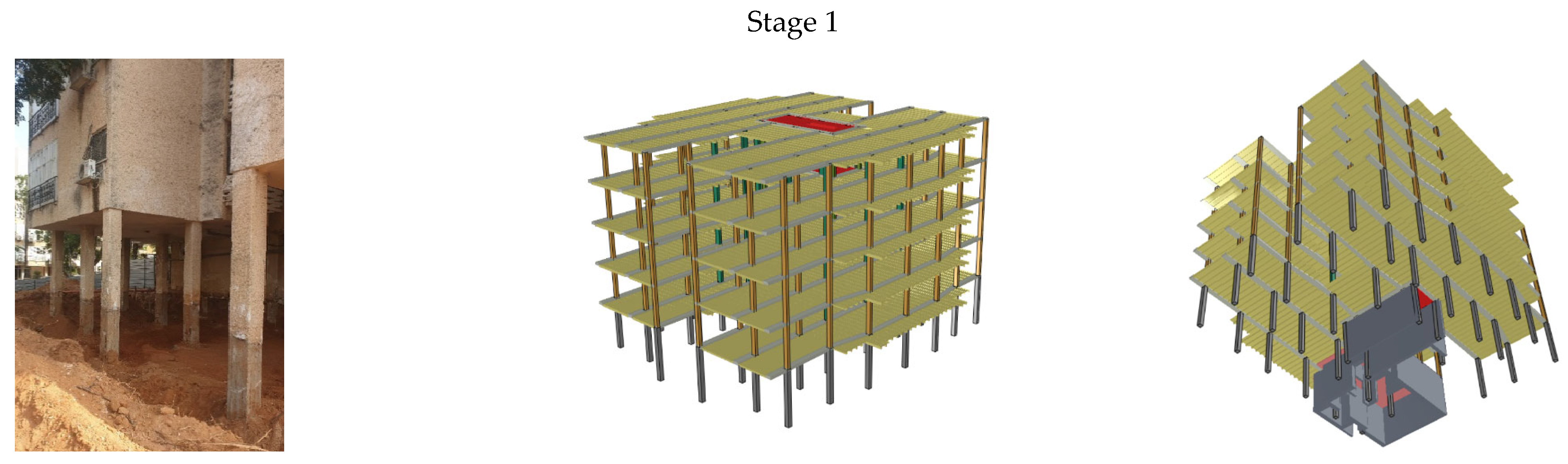
- Stage 1—after completing the excavation for strengthening the foundations: the model was similar to that in stage 0, considering the excavation work required for strengthening the foundation that opened the ground floor columns by about 1 m (see Figure 2b);
- -
- Stage 2—after completing the ground floor columns, walls, and ceilings: the model was based on that used in stage 1, when walls and stiffening cores were added on the ground floor of the building;
- -
- Stages 3–9—after completing the columns, walls, and ceiling of the first to seventh floors, respectively;
- -
- Stage 10—structure in the service condition after completing all non-structural elements (the model based on that used in step 9 and full-service loads).
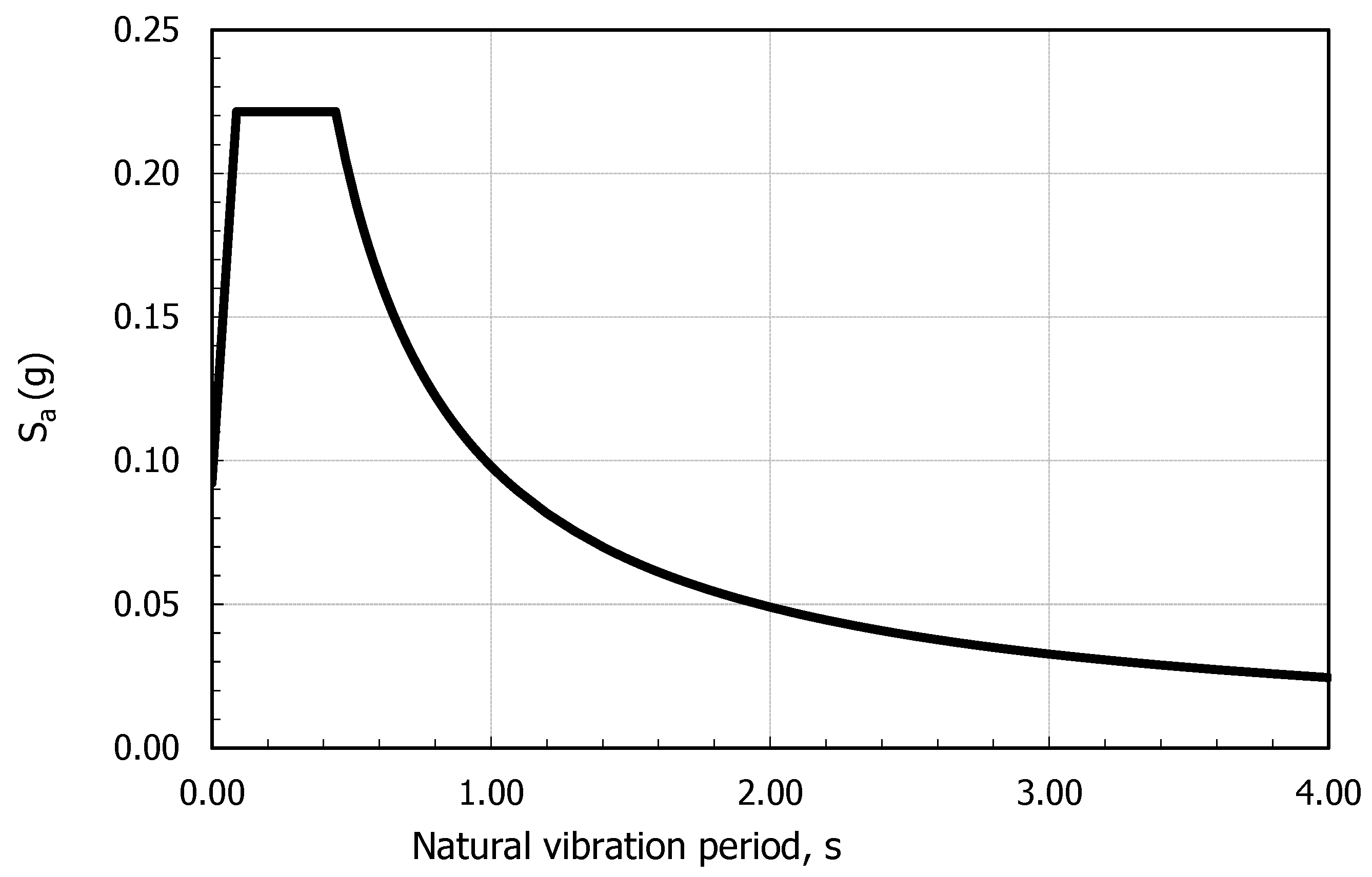
6.2. Comparing and Discussing the Dynamic Characteristics of the Building at Each Strengthening/Upgrading Stage (1–10)
- -
- Peak ground acceleration (PGA), Z = 0.06;
- -
- Horizontal spectral acceleration coefficient for the low natural vibration period, Ss = 0.14;
- -
- Horizontal spectral acceleration coefficient for the natural vibration period of 1 s, S1 = 0.04;
- -
- Site soil class—type D;
- -
- Site coefficient for short vibration periods, Fa = 1.6;
- -
- Site coefficient for long vibration periods, Fv = 2.4;
- -
- Seismic force reduction coefficient that considers nonlinear deformations in the building, K = 1.5;
- -
- Importance coefficient of the building, I = 1.
7. Conclusions
Author Contributions
Funding
Institutional Review Board Statement
Informed Consent Statement
Data Availability Statement
Conflicts of Interest
References
- IS 413; Design Provision for Earthquake Resistance of Structure, Amendment 5. Standard Institution of Israel: Tel Aviv, Israeli, 2013.
- EN 1998-1; Eurocode 8: Design of Structures for Earthquake Resistance—Part 1: General Rules, Seismic Actions and Rules for Buildings. National Standards Authority of Ireland: Dublin, Ireland, 2003.
- EN 1998-3; Eurocode 8: Design of Structures for Earthquake Resistance—Part 3: Assessment and Retrofitting of Buildings. National Standards Authority of Ireland: Dublin, Ireland, 2003.
- ASCE 7-05; Minimum Design Loads for Buildings and Other Structures. American Society of Civil Engineers: Reston, VA, USA, 2013.
- Iskhakov, I.; Yehuda, S.; Ribakov, Y. Experimental and Numerical Investigation of a Real Four-Story Building with an Open Ground Floor in Seismic Region for Proper Strengthening. Adv. Mater. Sci. Eng. 2024, 2024, 7812859. [Google Scholar] [CrossRef]
- Sonuvar, M.O.; Ozcebe, G.; Ersoy, U. Rehabilitation of reinforced concrete frames with reinforced concrete infills. ACI Struct. J. 2004, 101, 494–500. [Google Scholar]
- Canbay, E.; Ersoy, U.; Ozcebe, G. Contribution of reinforced concrete infills to seismic behavior of structural systems. ACI Struct. J. 2003, 100, 637–643. [Google Scholar]
- Kaplan, H.; Yilmaz, S. Seismic Strengthening of Reinforced Concrete Buildings. In Earthquake-Resistant Structures—Design, Assessment and Rehabilitation; BoD–Books on Demand: Schleswig-Holstein, Germany, 2012; Available online: www.researchgate.net/publication/221926358_Seismic_Strengthening_of_Reinforced_Concrete_Building (accessed on 23 April 2023). [CrossRef]
- Gião, R.; Lúcio, V.; Chastre, C. Innovative Seismic Strengthening Techniques to Be Used in RC Beams’ Critical Zones. Buildings 2023, 13, 95. [Google Scholar] [CrossRef]
- Uva, G.; Porco, F.; Fiore, A. Appraisal of masonry infill walls effect in the seismic response of RC framed buildings: A case study. Eng. Struct. 2012, 34, 514–526. [Google Scholar] [CrossRef]
- Manos, G.C.; Papanaoum, E. Assessment of the earthquake behavior of Hotel Ermionio in Kozani, Greece constructed in 1933 before and after its recent retrofit. Retrofit. Herit. Struct. 2013, 25, 25–39. [Google Scholar]
- Nagashima, S.; Mochizuki, M.; Suzuki, M.; Ninomiya, T.; Tamura1, R.; Nakano, T.; Kinoshita, M. Structural performance evaluation of a historical landmark built in the Taisho period. Retrofit. Herit. Struct. 2013, 53, 53–63. [Google Scholar]
- Offir, Y.; Shohat, A.; Cohen, A. Seismic retrofit of B’nai Zion hospital using an innovative damped rocking-mass system. In Proceedings of the 16th World Conference on Earthquake, Santiago, Chile, 9–13 January 2017. [Google Scholar]
- Uranjek, M.; Dolinšek, B.; Gostič, S. Seismic strengthening of churches as a part of earthquake renewal in the Posočje region, Slovenia. Earthq. Resist. Eng. Struct. VIII 2011, 120, 237–248. [Google Scholar]
- Kim, D.H. Assessment on Natural Frequencies of Structures using Field Measurement and FE Analysis. Int. J. High-Rise Build. 2014, 3, 305–310. [Google Scholar]
- Iskhakov, I.; Ribakov, Y. Experimental and numerical investigation of a full-scale multistory RC building under dynamic loading. Struct. Des. Tall Spec. Build. 2005, 14, 299–313. [Google Scholar] [CrossRef]
- Iskhakov, I.; Ribakov, Y. Selection of Base Isolation System Properties Using a Three-Story Structural Part Impulse Tests. Eur. Earthq. Eng. 2005, XIX, 38–42. [Google Scholar]
- Chen, M.C.; Pantoli, E.; Wang, X.; Astroza, R.; Ebrahimian, H.; Hutchinson, T.C.; Conte, J.P.; Restrepo, J.I.; Marin, C.; Walsh, K.D.; et al. Full-Scale Structural and Nonstructural Building System Performance during Earthquakes: Part I—Specimen Description, Test Protocol, and Structural Response. Earthq. Spectra 2016, 32, 737–770. [Google Scholar] [CrossRef]
- Fajfar, P.; Godec, M.A. Compression of Numerical Analysis and Full-Scale Tests for Free Vibration of Three Reinforced Concrete Buildings; IKPIR Publication: Ljubljana, Slovenija, 1982; p. 24 A. [Google Scholar]
- ETABS Verification Examples, CSI Computers and Structures; Computers & Structures, Inc.: Walnut Creek, CA, USA, 2016.
- STRAP Verification Manual, Structural Analysis Program; Version 2014; ATIR Engineering Software Ltd.: Tel Aviv, Israel, 2014.
- Specifications for Raspberry Shake RS4D—Your RS4D Personal Seismograph & Accelerograph—An IoT Home-Automation Device Born on: February. 2017. Available online: https://manual.raspberryshake.org/_downloads/SpecificationsforRaspberryShake4DMEMSV4.pdf (accessed on 14 May 2023).
- Specifications for: Raspberry Shake 3D—Your 3D Personal Seismograph, An IoT Home-Automation Device Born on: February. 2017. Available online: https://manual.raspberryshake.org/_downloads/SpecificationsforRaspberryShake3D.pdf (accessed on 14 May 2023).
- SWARM—Seismic Wave Analysis and Real Time Monitor: User Manual and Reference Guide, Version 3.1.0; February 2020. Available online: https://volcanoes.usgs.gov/software/swarm/doc/swarm_v3.pdf (accessed on 28 May 2023).
- WinQuake Documentation, Version 3.4.2; 3 December 2018. Available online: http://webtronics.com/wqdocs/ (accessed on 28 May 2023).
- Anthony, R.E.; Ringler, A.T.; Wilson, D.C.; Wolin, E. Do Low-Cost Seismographs Perform Well Enough for Your Network? An Overview of Laboratory Tests and Field Observations of the OSOP Raspberry Shake 4D. Seismol. Res. Lett. 2019, 90, 219–228. [Google Scholar] [CrossRef]
- Staat, E. Comparing Inexpensive Raspberry Shakes to Broadband Seismometers in Estimating Deep Earth Structure through The Use of Receiver Functions. Available online: https://raspberryshake.org/wp-content/uploads/StaatPoster465-3.0s_compressed.pdf (accessed on 28 May 2023).


| Phase No. | Phase Name |
|---|---|
| 0 | The existing building before strengthening |
| 1 | After excavation for casting the building raft |
| 2 | After strengthening the existing and casting new ground floor columns, walls, and floor diaphragms |
| 3 | Same as phase 2 on the 1st floor |
| 4 | Same as phase 2 on the 2nd floor |
| 5 | Same as phase 2 on the 3rd floor |
| 6 | Same as phase 2 on the 4th floor (roof of the existing building and upgrading the upper horizontal diaphragm) |
| 7 | Casting columns, walls, and floor diaphragms on the 5th floor (new floor) |
| 8 | Same as phase 7 on the 6th floor |
| 9 | Same as phase 7 on the 7th floor (roof of the strengthened and upgraded building) |
| 10 | The strengthened and upgraded building |
| Stage | Mode | |||||||||
|---|---|---|---|---|---|---|---|---|---|---|
| 1 | 2 | 3 | 4 | 5 | 6 | 7 | 8 | 9 | 10 | |
| 0 | 0.574 | 0.569 | 0.362 | 0.167 | 0.162 | 0.115 | 0.092 | 0.089 | 0.068 | 0.067 |
| 1 | 0.582 | 0.580 | 0.366 | 0.169 | 0.163 | 0.116 | 0.093 | 0.090 | 0.069 | 0.068 |
| 2 | 0.521 | 0.498 | 0.346 | 0.159 | 0.154 | 0.113 | 0.089 | 0.086 | 0.068 | 0.067 |
| 3 | 0.396 | 0.380 | 0.271 | 0.122 | 0.118 | 0.089 | 0.072 | 0.070 | 0.056 | 0.051 |
| 4 | 0.281 | 0.268 | 0.197 | 0.099 | 0.093 | 0.074 | 0.070 | 0.066 | 0.054 | 0.028 |
| 5 | 0.204 | 0.182 | 0.137 | 0.099 | 0.095 | 0.075 | 0.039 | 0.035 | 0.028 | 0.022 |
| 6 | 0.216 | 0.186 | 0.133 | 0.054 | 0.049 | 0.037 | 0.027 | 0.025 | 0.020 | 0.020 |
| 7 | 0.279 | 0.240 | 0.167 | 0.069 | 0.060 | 0.045 | 0.034 | 0.031 | 0.024 | 0.024 |
| 8 | 0.341 | 0.292 | 0.205 | 0.087 | 0.075 | 0.057 | 0.043 | 0.038 | 0.029 | 0.028 |
| 9 | 0.381 | 0.326 | 0.227 | 0.101 | 0.087 | 0.065 | 0.051 | 0.044 | 0.035 | 0.034 |
| 10 | 0.432 | 0.369 | 0.252 | 0.109 | 0.094 | 0.070 | 0.055 | 0.048 | 0.038 | 0.037 |
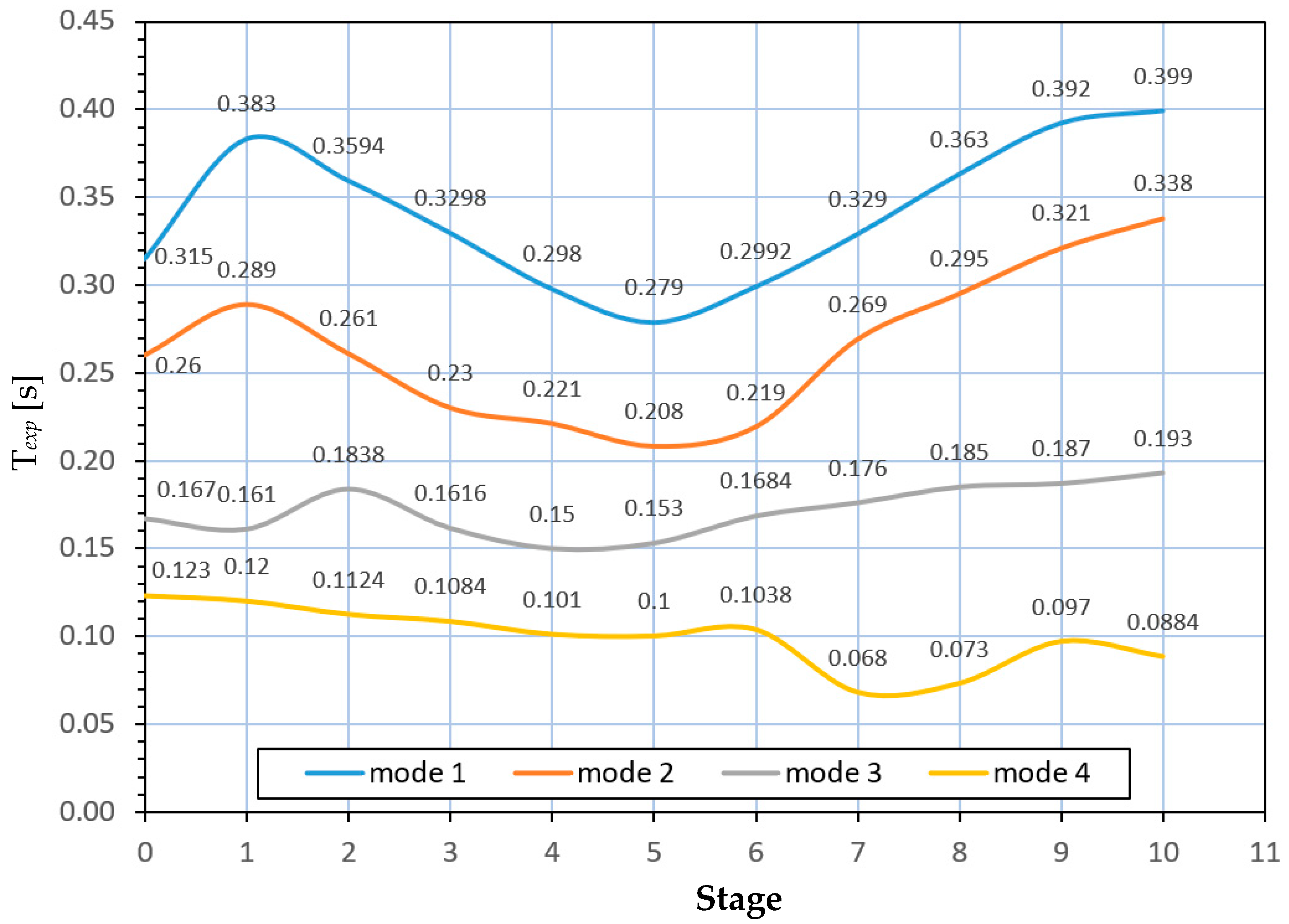
| Stage | Mode | |||
|---|---|---|---|---|
| 1 | 2 | 3 | 4 | |
| 0 | 0.315 | 0.260 | 0.167 | 0.123 |
| 1 | 0.383 | 0.289 | 0.161 | 0.120 |
| 2 | 0.360 | 0.261 | 0.184 | 0.124 |
| 3 | 0.330 | 0.230 | 0.162 | 0.108 |
| 4 | 0.298 | 0.221 | 0.171 | 0.101 |
| 5 | 0.279 | 0.208 | 0.162 | 0.100 |
| 6 | 0.299 | 0.219 | 0.150 | 0.104 |
| 7 | 0.329 | 0.269 | 0.153 | 0.068 |
| 8 | 0.363 | 0.295 | 0.168 | 0.073 |
| 9 | 0.392 | 0.321 | 0.176 | 0.097 |
| 10 | 0.399 | 0.338 | 0.193 | 0.088 |
Disclaimer/Publisher’s Note: The statements, opinions and data contained in all publications are solely those of the individual author(s) and contributor(s) and not of MDPI and/or the editor(s). MDPI and/or the editor(s) disclaim responsibility for any injury to people or property resulting from any ideas, methods, instructions or products referred to in the content. |
© 2024 by the authors. Licensee MDPI, Basel, Switzerland. This article is an open access article distributed under the terms and conditions of the Creative Commons Attribution (CC BY) license (https://creativecommons.org/licenses/by/4.0/).
Share and Cite
Iskhakov, I.; Yehuda, S.; Ribakov, Y. Methodology and Monitoring of the Strengthening and Upgrading of a Four-Story Building with an Open Ground Floor in a Seismic Region. Appl. Sci. 2024, 14, 7581. https://doi.org/10.3390/app14177581
Iskhakov I, Yehuda S, Ribakov Y. Methodology and Monitoring of the Strengthening and Upgrading of a Four-Story Building with an Open Ground Floor in a Seismic Region. Applied Sciences. 2024; 14(17):7581. https://doi.org/10.3390/app14177581
Chicago/Turabian StyleIskhakov, Iakov, Sharon Yehuda, and Yuri Ribakov. 2024. "Methodology and Monitoring of the Strengthening and Upgrading of a Four-Story Building with an Open Ground Floor in a Seismic Region" Applied Sciences 14, no. 17: 7581. https://doi.org/10.3390/app14177581