Article

The Influence of Rock Thermal Stress on the Morphology and Expansion Pattern of the Plastic Zone in the Surrounding Rock of a Deep-Buried Tunnel under High Geothermal Temperature Conditions

1
College of Water Resources and Construction Engineering, Shihezi University, Shihezi 832000, China
2
College of Water Resources and Civil Engineering, Xinjiang Agricultural University, Urumqi 830052, China
3
Xinjiang Water Resources and Hydropower Survey Design and Research Institute Limited Liability Company, Urumqi 830052, China
4
State Key Laboratory of Hydraulics and Mountain River Engineering, Sichuan University, Chengdu 610065, China
5
College of Water Resource and Hydropower, Sichuan University, Chengdu 610065, China
*
Authors to whom correspondence should be addressed.
Appl. Sci. 2024, 14(17), 7589; https://doi.org/10.3390/app14177589
Submission received: 28 June 2024 / Revised: 19 August 2024 / Accepted: 22 August 2024 / Published: 28 August 2024
(This article belongs to the Section Applied Thermal Engineering)

Abstract

:
The extent of the plastic zone is critical in determining the stability and extent of damage to the surrounding rock in tunnels, crucial for designing support structures and thermal insulation layers. This study focuses on understanding how rock thermal stress affects the expansion of the plastic zone in deep-buried tunnels subjected to high geothermal temperatures, based on the derivation of the boundary line formula of the plastic zone in a high geothermal tunnel, and combined with the test results of the hydraulic fracturing method in a high geothermal tunnel of the Bulunkou Hydropower Station in Xinjiang. The findings indicate that thermal stress in the rock mass slows the growth of the plastic zone but significantly increases its extent. However, the influence of thermal stress on the shape and size of the plastic zone is less significant compared to the lateral pressure coefficient. In conditions of high geothermal temperature and geostress, rock mass thermal stress induces substantial changes in the morphology and extent of the plastic zone, which cannot be overlooked and can lead to significant errors if not properly considered. The theoretical formulas derived from engineering analysis, along with observed patterns of plastic zone expansion, demonstrate practical applicability.

1. Introduction

Major infrastructure is a critical driver and pillar of national economic development. Specifically, the scale, growth rate, and complexity of China’s major infrastructure projects are among the highest in the world, with the implementation of national strategies such as “Strong Transportation Country”, “Strong Ocean Country”, “Water Network Construction”, and the “Belt and Road” Initiative.
Several groundbreaking projects, such as high-altitude and cold-weather railways, extremely deep underground ventures, and extraordinarily long undersea tunnels, have introduced unparalleled opportunities and challenges to the progress of engineering construction science and technology. As a result, to keep pace with rapid economic and social development, tunnel construction for diverse purposes is actively advancing. Specifically, the construction of deep tunnels, defined as those exceeding 600 m [1], frequently encounter geological hazards such as high geothermal temperature and high geopathic stress during construction. These factors have become significant obstacles to their rapid development. In high-temperature and high-stress environments, the surrounding rock of deep-buried tunnels undergoes extensive deformation and damage, primarily due to the uneven expansion of the plastic zone [2]. Analyzing the geometry and expansion pattern of the plastic zone has always been crucial to comprehend the damage mechanisms in tunnels and controlling the stability of the surrounding rock.
Through extensive global scholarly exploration, the morphology and expansion characteristics of the plastic zone in the surrounding rock of tunnels under non-uniform stress fields have been thoroughly investigated, resulting in continuous enhancement and refinement of plastic zone theory. The size of the plastic zone in rock surrounding tunnels is influenced by key rock mechanical parameters such as cohesion, internal friction angle, support resistance, and ground stress levels. The shape of the plastic zone depends on the distribution of stress within the rock mass. Particularly, high-ground stress is predominantly responsible for the expansion. J.K. Wu [3] and colleagues elucidated the extension law of the plastic zone in four types of deep-well peripheral rocks. On the other hand, Zheng Yingren and co-authors [4] deduced the equation for the boundary line of the plastic zone in the peripheral rocks of a circular roadway, revealing its tongue or sickle-shaped behavior. Recently, Zhao [5] and collaborators discovered that apart from circular and elliptical forms, the plastic zone morphology in a roadway under a non-uniform stress field can also manifest as a butterfly shape. To validate the range and morphology of the plastic zone under varying stress conditions, Chen Li-wei et al. [6,7] utilized the boundary line equation of the plastic zone in the tunnel surrounding rock under non-uniform stress fields. Guo Xiaofei [8] and colleagues employed FLAC 3D to simulate the plastic zone morphology in the surrounding rock of a circular tunnel, proposing corresponding determination criteria. Ma Nianjie et al. [9] elucidated the theoretical basis for the development of circular, elliptical, and butterfly-shaped plastic zones in the non-uniform stress field of circular roadway surrounding rock. Furthermore, based on observations in the high-stress soft-rock roadway of Qujiang coal mine, Wang Weijun [10] posited that the destabilization of the roadway surrounding rock stems from the pernicious expansion of the plastic zone was induced by localized distortion of the plastic ring.
Furthermore, the high geothermal temperature is known to bear a significant impact on plastic zone extension. The expansion of the rock body caused by high temperature, influenced by geothermal flow and constrained by the surrounding rock, generates thermal stress. Zheng Yingren et al. [4] proposed an approximate formula for calculating the temperature stress field of the rock body. Additionally, He Manchao, et al. [11] suggested that for each degree Celsius change in temperature, the rock generates thermal stress ranging from 0.4 to 0.5 MPa. Meng Wei et al. [12] investigated the influence of geothermal temperature gradients on predicting rock bursts, highlighting that thermal stress can double under constant pressure and horizontal principal stress conditions. They found that at the Sangzhuling tunnel site, rock thermal stress constitutes approximately 61% of gravitational stress. They emphasized that neglecting this thermal stress in rock burst predictions could lead to significant inaccuracies. Li Tianbin et al. [13] performed experimental research focusing on the effects of temperature on tunnel rock bursts under thermal coupling conditions. Their study aimed to understand how thermal factors contribute to the occurrence of rock bursts in tunnels. Furthermore, Yan Jian et al. [14] carried out a comparative analysis of the impact of high geostress and high geothermal temperature on rock bursts in the Sangzhuling and Bayu tunnels. Their research aimed to elucidate how these factors individually and collectively influence the propensity for rock bursts in tunnel environments.
Previous studies by experts have primarily focused on the impact of high geopathic stress on plastic zone expansion, along with the impact of temperature on thermal stress and surrounding rock stability. However, not many studies have explored the specific impact of thermal stress on the plastic zone expansion of tunnel surrounding rock, particularly in tunnels subject to both high geothermal temperatures and high geopathic stresses. This gap in research stems from the vertical stress measured by the hydraulic fracturing method in high geothermal environments failing to account for thermal stresses induced by the geothermal temperature gradient [12], thus resulting in potential deviations in the analysis of plastic zone expansion laws. Therefore, it is imperative to investigate the influence of these unaccounted thermal stresses on the expansion patterns of the surrounding rock’s plastic zone in tunnels characterized by high geothermal temperatures and high geostresses using hydraulic fracturing methods.
This paper emphasizes the high-temperature diversion tunnel of the Bulunkou–Konger hydropower station as the research subject. In particular, it assesses the morphology and expansion patterns of the plastic zone in tunnels with high geothermal temperatures and high geostresses. This study examines the influence of thermal stress on plastic zone morphology and surrounding rock stress characteristics through engineering examples by integrating plastic zone boundary equations that consider thermal stress in rock bodies with measurement data obtained from hydraulic fracturing methods. The endeavor is to provide a theoretical framework for understanding plastic zone expansion laws in tunnels along with the damage mechanisms of surrounding rock, facilitating tunnel excavation and support in practical applications.

2. High Geothermal and High Geostress Tunnel Evolution Law and Its Coupling Characteristics

2.1. Engineering Overview

The high geothermal section of the Bulunkou–Konger Hydropower Station diversion power generation tunnel spans a total length of 4111 m, situated at burial depths ranging from 500 to 1500 m. The average rock temperature during construction exceeds 90 °C, reaching a maximum of 143 °C, a condition rare both domestically and internationally due to the elevated and extensive range of geothermal temperatures. Geostress levels surpassing 20 MPa are classified as high geostress in this context [15]. It is evident that this tunnel section falls within the high geostress zone, owing to the stress environment and lithology of the surrounding rock. The rock mass in this section is hard and intact, devoid of stratification and groundwater outcrop. During construction, the influence of internal water pressure is not considered.

2.2. Pilot Program

The hydraulic fracturing method [16], recommended by the Test Methods Committee of the International Society of Rock Mechanics for determining rock stress, was employed to ensure the acquisition of reliable and precise ground stress data. This method is particularly suitable for intact brittle rock formations. It involves pressurizing the borehole using a hydraulic pump at the intended measurement depth to induce fractures in the borehole wall. The pressure at each characteristic point and the orientation of the fractures are determined during the fracturing process. Next, the magnitude and direction of the geostress in the rock mass near the measurement point are calculated based on the readings from the pump pressure gauge head.
The in situ field test was conducted in a test chamber situated perpendicular to the excavated main cavern, approximately 100 m from the main cave section and at a significant burial depth. The test chamber was excavated in a circular cross-section parallel to the tunnel axis. Three boreholes—YBK1, YBK2, and YBK3—were drilled straight, each spanning approximately 560 m in length and penetrating depths exceeding 2.5 times the tunnel span. The rock encountered in these boreholes exhibits notable hardness, with microfractures observed in certain deep cores. The specific longitudinal arrangement of the test points is outlined in detail in Table 1.

2.3. Test Results

The stress data measured from the three boreholes along the tunnel are presented in Table 2, offering a comprehensive reflection of the stress field distribution within the study area due to the extensive coverage of measurement points. The three principal stresses, denoted by σH > σZ > σh, align with the tectonic features of the primary active fractures within the project area, exhibiting a slip nature.
Through linear fitting analysis, it was determined that the compound correlation coefficients (R2) of the fitted curves for the three boreholes ranged between 0.92 and 0.99, indicating a more satisfactory fitting effect. This approach effectively forecasts the variations in principal stresses and temperatures across different depths of boreholes, thereby illustrating the spatial evolution of the tunnel under conditions of high geothermal temperatures and geostatic stresses (Figure 1). It is apparent that both the principal stresses and temperatures in the three boreholes increase linearly with depth. Furthermore, the gradient of the maximum horizontal principal stress exceeds that of the minimum horizontal principal stress, indicating a higher sensitivity of the maximum horizontal principal stress to variations in borehole depth.

3. Plastic Zone Expansion Law

3.1. Theoretical Calculation of the Plastic Zone

The following basic assumptions are made in order to facilitate the application of the Mohr–Coulomb criterion: (1) the surrounding rock is homogeneous, isotropic, and linear-elastic; (2) the circular tunnel is analyzed as a plane strain problem. On the basis of the elastic stress field equations for radial, circumferential, and tangential stresses of the tunnel surrounding rock [4], the stress solution for the surrounding rock of a circular tunnel in polar coordinates can be derived. This paper employs a simplified coupling method, wherein the theoretical model utilizes a linear superposition of the stress field and temperature. This approach simplifies the consideration of boundary forces and temperature fields, concentrating exclusively on how the temperature field of the surrounding rock affects the stress field while disregarding the reciprocal influence of the stress field of the surrounding rock on the temperature field. Additionally, Meng Wei [12] noted that the vertical stress obtained by the hydraulic fracturing method in a high geothermal temperature environment does not account for thermal stress. The self-gravity stress combined with the thermal stress of the rock body σT is considered in order to better reflect reality. Figure 2 illustrates the mechanical model of the tunnel’s surrounding rock. Consequently, the stress at any point outside the tunnel is as follows:
σ r , T = ( 1 + λ ) σ z + σ T 2 ( 1 r 0 2 R 0 2 ) + ( λ 1 ) σ z σ T 2 ( 1 4 r 0 2 R 0 2 + 3 r 0 4 R 0 4 ) cos 2 θ + p i r 0 2 R 0 2 σ θ , T = ( 1 + λ ) σ z + σ T 2 ( 1 + r 0 2 R 0 2 ) ( λ 1 ) σ z σ T 2 ( 1 + 3 r 0 4 R 0 4 ) cos 2 θ p i r 0 2 R 0 2 τ r θ , T = ( λ 1 ) σ z + σ T 2 ( 1 + 2 r 0 2 R 0 2 3 r 0 4 R 0 4 ) sin 2 θ + τ i r 0 2 R 0 2
where σz represents the self-gravitational stress (MPa); r0 denotes the radius of the cave chamber (m); R0 signifies the radius of the plastic zone at the specified point (m); θ is the polar angle (°) measured from the polar axis; λ denotes the lateral pressure coefficient; pi represents the radial stress acting on the surrounding rocks in the support (MPa); τi denotes tangential stress acting on the surrounding rocks in the support (MPa); σr, σθ and τrθ represent the radial and tangential stresses respectively acting on the surrounding rocks (MPa); σT denotes the thermal stress of the rock body (MPa), σ T = μ β E Z . β is the expansion coefficient of the rock body (°C−1); μ represents the ground temperature gradient (°C/100 m), μ = T T 0 H h ; T signifies the temperature at the burial depth of H (°C); T0 stands for the temperature of the thermostatic zone (°C); E is the modulus of elasticity (MPa); Z signifies the distance from the thermostatic zone (m), Z = H h ; H represents the depth of the buried depth (m); and h denotes the distance of the thermostatic zone from the ground surface (m).
The boundary of the plastic zone is frequently assessed using the plasticity criterion in conjunction with the stress within the plastic zone. Consequently, the elastic stress field Equation (1) is substituted into Carnest’s plasticity criterion Equation (2) [4].
sin φ = ( σ θ   e σ r   e ) 2 + ( 2 τ e   r θ ) 2 σ θ   e + σ r   e + 2 c c o t φ
The plasticity criterion Equation (2) is rearranged to derive the boundary line Equation (3) for the tunnel envelope’s plastic zone under thermal coupling.
cos 2 2 θ a 2 ( 4 α 4 sin 2 φ ω 1 2 + ω 2 ) + a cos 2 θ 2 ( b 2 p i ) ω 1 4 sin 2 φ ( b + 2 ccot φ ) α 2 + ( b + 2 ccot φ ) 2 sin 2 φ ( b 2 p i ) 2 α 4 a 2 ω 2 2 8 τ i 2 α 4 + 4 a ω 2 τ i α 2 sin 2 θ = 0
where ω 1 = 1 + 3 α 4 2 α 2 ω 2 = 1 3 α 4 + 2 α 2 a = ( λ 1 ) σ z σ T b = ( 1 + λ ) σ z + σ T σ T = β E Z T T 0 H h α = r 0 R 0 .
In a non-uniform stress field, provided that the stress and the properties of the surrounding rock are known (as per Table 2), the boundary of the plastic zone can be determined by employing Equation (3), we can derive the implicit Equation (4) involving the binary octave equation concerning (r0/R0) and (θ). This equation allows us to examine the morphology of the plastic zone surrounding the circular tunnel in a non-uniform stress field and analyze its expansion characteristics.
A r 0 R 0 8 + B r 0 R 0 6 + C r 0 R 0 4 + D r 0 R 0 2 + E = 0
where A = 27 ( λ 1 ) σ z σ T 2 + 9 ( λ 1 ) σ z σ T 2 cos 4 θ B = 36 ( λ 1 ) σ z σ T 2 12 ( λ 1 ) σ z σ T 2 cos 4 θ C = 2 ( λ 1 ) σ z σ T 2 + 2 ( 1 + λ ) σ z + σ T 2 + 6 ( λ 1 ) σ z σ T 2 cos 4 θ + 8 ( λ 1 ) σ z σ T ( 1 + λ ) σ z + σ T cos 2 θ D = 6 ( λ 1 ) σ z σ T 2 2 ( λ 1 ) σ z σ T 2 cos 4 θ 2 ( λ 1 ) σ z σ T ( 1 + λ ) σ z + σ T cos 2 θ + 4 ( λ 1 ) σ z σ T c cos 2 θ cot φ E = 2 ( λ 1 ) σ z σ T 2 ( 1 + λ ) σ z + σ T 2 4 c 2 + ( 1 + λ ) σ z + σ T 2 4 c 2 cos 2 φ 4 ( 1 + λ ) σ z + σ T c sin 2 φ .
Because of the intricate and lengthy nature of the implicit equation, directly solving for the radius of the plastic zone presents considerable challenges. Wolfram Mathematica 13.0 software is utilized for processing the solution effectively. By inputting relevant parameters such as cohesion, internal friction angle, tunnel radius, and burial depth a numerical analytical solution for the radius of the plastic zone surrounding the rock is derived using an iterative method. This approach guarantees calculation accuracy to within 1%.

3.2. Distribution Pattern and Expansion Law of Plastic Zone in High Geothermal and High Geostress Tunnels

Changes in geostress and geothermal temperatures are the principal factors driving the expansion of the plastic zone. Their impact on the plastic zone surrounding the rock is manifested in the variations of lateral pressure coefficients and thermal stress within the rock, influenced by the stress characteristics of the surrounding rock. Understanding the interaction among these factors is crucial for analyzing the laws governing the evolution of the plastic zone in tunnels subjected to high geothermal temperatures and high geostress.

3.2.1. Distribution Pattern and Expansion Law of Tunnel Plastic Zone under High Geostress Effect

Assuming that the temperature remains constant both inside and outside the surrounding rock after tunnel excavation, without the presence of support lining, and considering temperatures below 400 degrees, the influence of high-temperature thermal stress on the strength of the surrounding rock is deemed negligible [17]. Consequently, it is posited here that temperature has no impact on the mechanical parameters of the rock. To elucidate the impact of the high geostress environment on the expansion law of the tunnel’s plastic zone, parameters identical to those in Table 2 are utilized. Utilizing Equation (4), and given that the surrounding rock of the tunnel is subjected to high geostress, and cannot exhibit plastic behavior before tunnel excavation, the plastic zone’s shape and the expansion characteristics of the high geostress tunnel are elucidated by varying the lateral pressure coefficient (0.3 ≤ λ ≤ 2.8) to alter the stress state of the surrounding rock (Figure 3). Figure 3 illustrates the close relationship between the shape of the surrounding rock plastic zone and the lateral pressure coefficient. Under varying ground stress conditions, the plastic zone exhibits three primary shapes: circular, elliptical, and butterfly. As λ gradually increases from 0.3 to 2.8, the plastic zone expands through a sequence: vertical butterfly → circular → vertical ellipse → vertical butterfly → vertical butterfly → horizontal butterfly. The maximum radius of the plastic zone experiences rapid growth with λ. However, when the plastic zone is circular or elliptical, this growth is slow and linear. Conversely, for a butterfly-shaped plastic zone, the maximum radius increases exponentially with λ. These observations suggest that the expansion rate of the plastic zone varies depending on its shape and the lateral pressure coefficient.
The morphology and expansion pattern of the plastic zone in high-stress tunnels, as determined in this study, align with findings reported in the literature [18,19]. Both studies suggest that the lateral pressure coefficient increases, and the plastic zone transitions from a circular shape to an ellipsoid before ultimately adopting a butterfly configuration. The discrepancy in the extent of the plastic zone between the two studies is relatively minor, indicating strong consistency and supporting the applicability of the derived theoretical formulas.

3.2.2. Impact of Rock Thermal Stress on the Distribution Pattern of Plastic Zones in Tunnels Subject to High Geothermal Temperatures and High Geostresses

To explore the impact of thermal stress on the plastic zone, we generated plots depicting the morphology of the plastic zone at various temperatures and lateral pressure coefficients using Equation (4) (Figure 4). The findings indicate that in conditions of high geothermal temperature and high geostress, the plastic zone typically takes two primary shapes: elliptical and butterfly. The formation of a uniformly circular plastic zone is hindered by the influence of thermal stress on the rock mass. To succinctly explain the expansion patterns of the plastic zone in tunnels subjected to high geothermal temperature and high geostress, we conducted separate analyses based on the lateral pressure coefficient and temperature.
(1)
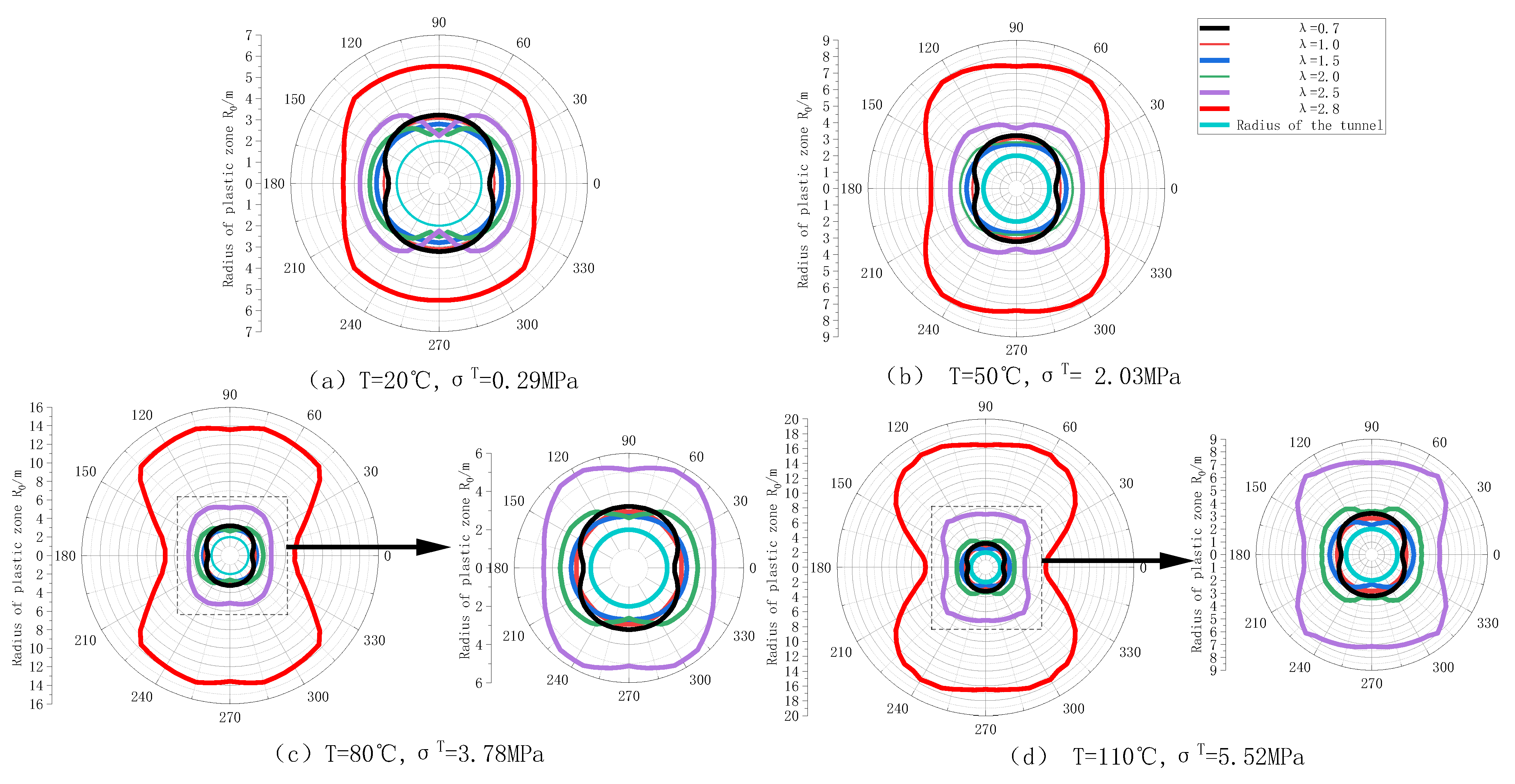
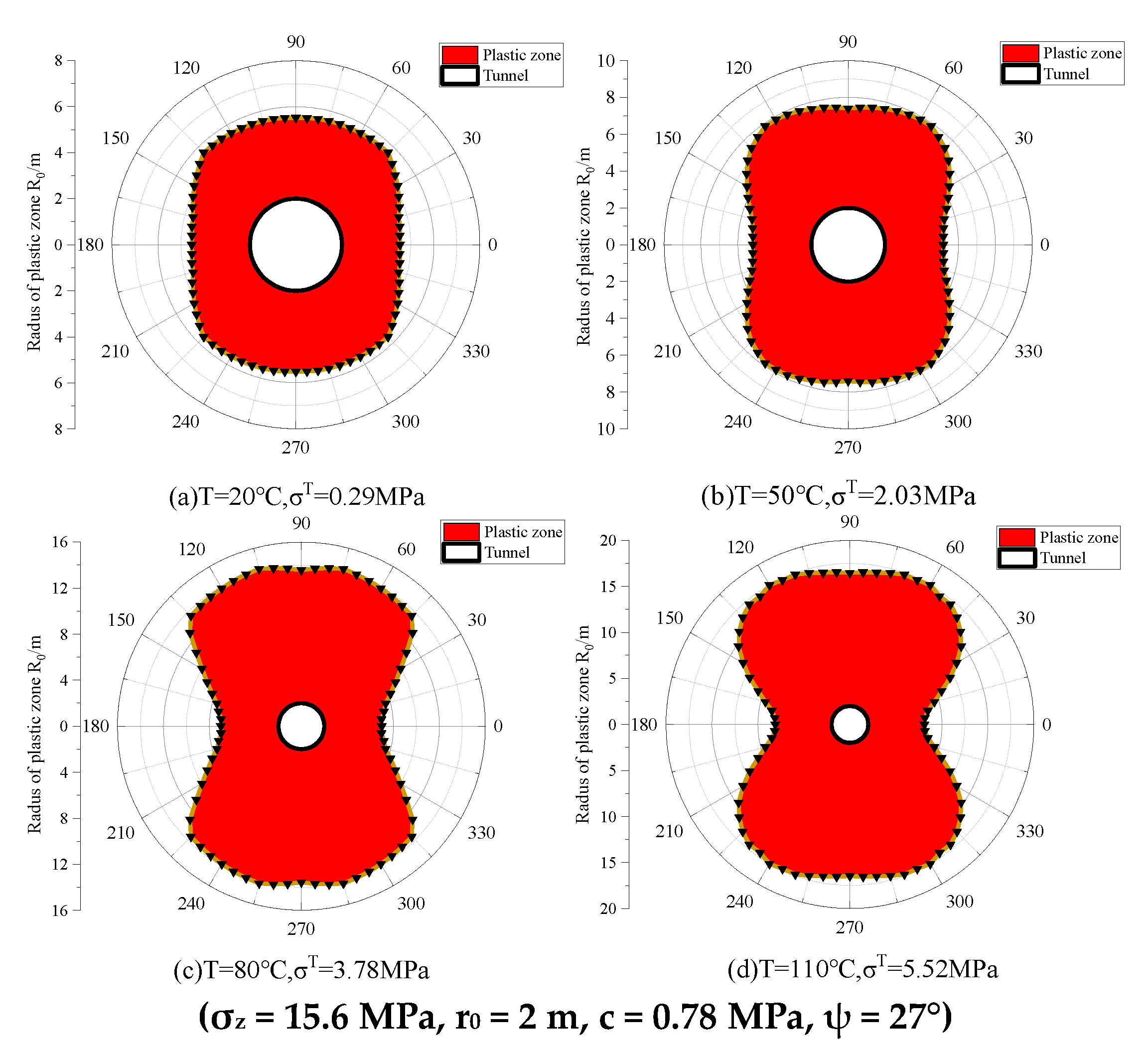
As the temperature gradually rises, so does the thermal stress within the rock body. Consequently, the geometry of the plastic zone undergoes significant changes from an ellipse to a butterfly shape. During this process, both the radius and extent of the plastic zone increase, with the rate of expansion progressively accelerating. Particularly noteworthy is the scenario where T reaches 80 °C and λ equals 2.8, resulting in a noticeable expansion of the plastic zone. In this case, the radius of the plastic zone expands from 7.86 m to 14.13 m. Conversely, at a temperature of 20 °C, the plastic zone assumes a standard vertical butterfly shape with λ at 2.5, distinctly different from the transverse butterfly shape observed under other conditions.
(2)
Variations in the lateral pressure coefficient induce changes in the fundamental shape of the plastic zone, characterized by both elliptical and butterfly forms, exhibiting a similar expansion pattern as described in Section 3.2.1. Within the range of 1.0 ≤ λ ≤ 2.0, the plastic zone assumes an elliptical shape, particularly evident at λ = 1.0, where it transitions from a circular to an irregularly expanded ellipse. As λ diverges further from 1, influenced by the profound stress environment, the plastic zone exhibits uneven expansion, narrowing horizontally while widening vertically along the longitudinal axis, thereby increasing the extent of the plastic zone. When λ < 1.0 or λ > 2.0, the plastic zone adopts an elliptical and butterfly-shaped configuration, mirroring the expansion law outlined in Section 3.2.1. At λ = 1.0 or λ > 2.0, the plastic zone extends towards the tunnel’s corners, resembling a complete butterfly shape, with a notable expansion in range. As λ increases to 2.8, the plastic zone takes on a double funnel shape, or transverse butterfly shape, with a substantial increase in range; however, its butterfly shape remains unchanged.

3.2.3. The Impact of Rock Thermal Stress on the Expansion Law of the Plastic Zone in High Geothermal Temperature and High Geostress Tunnels

The parameters are set as outlined in Table 2 to elucidate the impact of rock thermal stress induced by high geothermal conditions on the expansion pattern of the plastic zone in high geostress tunnels. Considering that 80 °C represents the typical temperature for the majority of high geothermal rock excavations, we analyzed the plastic zone morphology across various λ values using Equation (4) (Figure 5).
Undoubtedly, rock thermal stress moderately retards the morphological development of the plastic zone, resulting in a slightly slower expansion compared to scenarios where rock thermal stress is not considered. Compared to Section 3.2.1, under the same λ = 2, the plastic zone morphology remains unaltered, retaining its non-butterfly shape with a limited range. For λ ≤ 2, there is no significant change in the plastic zone morphology, resulting in a notably slower expansion trend. However, for λ > 2, the morphology and extent of the plastic zone exhibit heightened sensitivity to variations in the lateral pressure coefficient, expanding rapidly outward to form significant lobes. This trend becomes particularly pronounced after λ exceeds 2.8, with the butterfly lobe spreading noticeably at polar angles θ = 25~90°.
Figure 6 illustrates that when considering the thermal stress of the rock mass, the maximum radius of the plastic zone increases with larger values of λ > 1. The change in the radius of the plastic zone is especially pronounced in the surrounding rock with λ > 2, whereas the change in the radius is less significant for other values of λ. For instance, at λ = 2.8, the radius of the plastic zone exhibits a curvilinear increase in the polar angle θ = 0~55°, with a rapid initial increase from 5.17 m to 7.86 m, marking a 34.22% rise, followed by a gradual decrease to 7.4 m, reflecting a more stable decline of 5.85%.
Further investigation into the influence of thermal stress on the expansion of the plastic zone, as supported by ground stress measurements [4], reveals that under deep complex stress conditions, the lateral pressure coefficient exceeds 2. This condition predisposes the plastic zone to unstable forms, particularly the butterfly shape, which is prone to significant deformation. Therefore, λ = 2.8 holds significant research importance. By manipulating temperature to modulate the thermal stress state within the rock mass, we elucidate the evolution process of the plastic zone shape at λ = 2.8 (Figure 7).
Section 3.2.1 establishes that the fundamental morphology of the plastic zone adopts a butterfly shape at λ = 2.8. The plastic zone within the tunnel exhibits varied evolutionary patterns in response to temperature fluctuations. As depicted in Figure 7, at lower temperatures (T < 50 °C), the plastic zone undergoes rapid development, transitioning swiftly from an elliptical to a transverse butterfly shape, accompanied by a substantial increase in size. As temperature rises (T = 80 °C), the development of the plastic zone becomes more moderate, maintaining the transverse butterfly shape with a less pronounced increase in range. Further temperature increases (T = 110 °C) lead to less apparent development of the transverse butterfly-shaped plastic zone, with minimal changes in size. Even higher temperatures (T = 110 °C) result in the plastic zone maintaining its transverse butterfly shape but with indistinct development and minor size increases. Elevated lateral pressure coefficients combined with higher temperatures create larger temperature differentials among the surrounding rocks, resulting in more noticeable changes in plastic zone morphology. This condition facilitates the formation of butterfly-shaped plastic zones characterized by larger butterfly lobes and the extent of plastic damage, albeit with less pronounced size increases.
Using the maximum radius of the plastic zone as an indicator, the evolution of plastic zone morphology with temperature variations at λ = 2.8 was analyzed (Figure 8). The findings indicate that the maximum radius of the plastic zone shows an increasing trend with temperature changes, with the rate of increase initially rising and then declining. A stabilized plastic zone is observed at 20 °C ≤ T ≤ 50 °C with a significant increase, while a deteriorating plastic zone is evident at T ≥ 50 °C, and the rate of increase gradually diminishes at T ≥ 80 °C. Conversely, the minimum radius of the plastic zone generally increases at a more stable rate, yet it ultimately exhibits a larger discrepancy compared to the maximum radius of the plastic zone.
Set K 1 = Δ R max / Δ T , K 2 = Δ R min / Δ T , define K as the plastic zone sensitivity coefficient, and plot the K value curve at λ = 2.8 (Figure 9). When 50 °C ≤ T ≤ 110 °C, the values of K1 and K2 are observed to initially increase and then decrease with temperature. This further confirms that as T increases, the radius of the plastic zone varies significantly, transitioning from an elliptical shape to a butterfly shape, with both the maximum size and range of the plastic zone increasing progressively.
Analysis of Figure 10 reveals that the thermal stress of the rock mass directly correlates with the temperature, thereby increasing the maximum radius of the plastic zone as temperature rises. Notably, for temperatures at or above 80 °C, the radius of the plastic zone in the surrounding rock undergoes a significant increase, while changes are minimal for temperatures below 80 °C. At 110 °C, within the polar angle range of θ = 0~55°, there is a pronounced curvature in the relationship between the radius of the plastic zone in the surrounding rock and the polar angle, leading to a rapid increase from 8.11 m to 17.35 m. The radius of the plastic zone tends to be nearly circular at 20 °C, gradually transitioning to elliptical at 50 °C, and markedly butterfly shaped at 80 °C and 110 °C.
In general, the fundamental shape of the plastic zone in tunnels subjected to high geothermal temperatures and high geostress aligns with that observed in tunnels under high geostress alone, although the expansion pattern varies. Thermal stress from the rock mass slows down the expansion of the plastic zone in high geothermal and high-stress tunnels while increasing its spatial extent. At equivalent lateral pressure coefficients, higher temperatures lead to greater thermal stress within the rock mass, thereby hastening the geometric evolution of the plastic zone and expanding its range. Conversely, when the lateral pressure coefficient deviates significantly from unity (λ = 1), irregular plastic zones are more likely to form, characterized by larger plastic zone extents. Notably, the hierarchy of factors influencing plastic zone morphology is as follows: lateral pressure coefficient > thermal stress of the rock mass. Furthermore, the sensitivity of the maximum plastic zone radius to the lateral pressure coefficient diminishes as the thermal stress of the rock mass increases. Although the impact of thermal stress on the plastic zone is relatively smaller compared to the lateral pressure coefficient, it remains a significant factor deserving attention.

4. Engineering Practice

In the high geothermal environment, it has been shown that direct utilization of hydraulic fracturing stress measurements for analyzing plastic zone extension can result in significant errors [12]. This study centers on the Bulunkou high-temperature diversion tunnel, aiming to demonstrate the practical influence of rock thermal stress on the expansion of the plastic zone. It focuses on determining the radius of the plastic zone in the surrounding rock and the orientation of surrounding rock stress. According to the Code for Design of Railway Tunnels (J449-2016), the tunnel section under examination primarily consists of Class III surrounding rock, and no groundwater seepage was observed during construction. Boreholes SYZK1, SYZK2, and SYZK3 are located at distances of 0 + 454 m, 0 + 503 m, and 0 + 525 m, respectively, along the 6# construction branch hole. Each borehole penetrates an overlying rock layer approximately 560 m thick. To comprehensively study the characteristics of the plastic zone during tunnel construction, parameters were selected based on on-site test findings: the excavation radius for this section is r0 = 2 m, the initial rock temperature is t1 = 85 °C, the self-weight stress is σZ = 15.2 MPa, and the supporting force Pi = 0. These parameters, along with those of the surrounding rock, are detailed in Table 3.

4.1. Stress Comparison within the Plastic Zone

Given the complex terrain of the power diversion tunnels at the Bulunkou Hydropower Station project and practical challenges like mountain denudation, a comparative test was undertaken between the borehole sleeve core lifting method and the hydraulic fracturing method to validate the reliability of test results. Core release testing was conducted in three borehole test holes, and the measurement outcomes are presented in Table 4 and Table 5.
To assess the impact of thermal stress on stress within the plastic zone of the surrounding rock, stress analysis was conducted considering the combined influence of ground temperature and ground stress. This was calculated using Equation (3) and compared with monitored stress obtained via the core lifting method (see Figure 11 and Figure 12).
Based on actual measurements of various rock temperatures (T) and burial depths (H), as detailed in Table 3, it is evident that the thermal stress induced in the rock mass due to the ground temperature gradient in the high-temperature tunnel entrance at Bulun is
σ T   =   μ β E Z   =   β E T T 0     =     0 . 000005     ×     6000     ×     ( 85 20 )     =     1 . 95     MPa
Referring to Table 5, the self-weight stress of the tunnel is approximately 15.2 MPa, indicating that the rock thermal stress constitutes 12.83% of the self-weight stress. This means that the in situ ground stress measured by hydraulic fracturing in the tunnel lacks approximately 13% of the rock thermal stress. In Figure 11, at a σT of 1.95 MPa, the theoretically calculated radial stress ranges from 14.82 to 18.86 MPa, the circumferential stress ranges from 30.26 to 34.89 MPa, and the tangential stress ranges from −4.82 to −1.41 MPa. Most errors between the theoretical and monitoring values, corresponding to various λ, fall within the range of 10.32% to 33.40%, indicating significant discrepancies. The thermal stress within the rock mass significantly contributes to the overall stress. In Figure 12, theoretical values of maximum and minimum horizontal principal stresses for different λ notably diverge from field monitoring data, with errors ranging from 9.91% to 20.63% for maximum horizontal principal stresses and from 9.87% to 21.88% for minimum horizontal principal stresses. This substantial difference between theoretical predictions and field measurements underscores the significant impact of rock thermal stress, affirming the reliability and practical applicability of the theory. Therefore, relying solely on borehole in situ ground stress for analyzing the morphology and extent of the plastic zone would lead to considerable inaccuracies.

4.2. Comparison of the Radius of the Plastic Zone

R 0 = r 0 σ z ( 1 + λ ) + 2 c cot φ 1 sin φ 2 p i + 2 c cot φ 1 sin φ 2 sin φ × 1 + σ z ( 1 λ ) 1 sin φ cos 2 θ σ z ( 1 + λ ) + 2 c cot φ sin φ
To demonstrate the utility of the analytical solution, we selected the parameters from Table 3 and analyzed them by comparing the radius of the plastic zone obtained from Equation (4) with the Ruppneyt formula cited in the literature [20] (Figure 13).
The findings reveal a notable relative error ranging from 6.97% to 24.39% between the theoretical radius of the plastic zone and the value calculated using Ruppneyt’s formula, indicating significant discrepancies. This discrepancy primarily arises from considerations of self-weight stress and the influence of thermal stress on the rock mass, which leads to an evident expansion in the range of the plastic zone. This underscores the substantial impact of rock thermal stress on the morphology of the plastic zone. Therefore, accounting for the thermal stress of the rock mass in high-ground temperature environments results in plastic zone extension values that more accurately reflect real-world conditions. This highlights the practical utility of Formula (4) derived in this study and its alignment with engineering requirements.

5. Discussion

5.1. Expansion Law of the Plastic Zone in the Surrounding Rock of High Geothermal and High Geostress Tunnels

(1)
The plastic zone morphology and expansion law of the high geostress tunnel obtained in Section 3.2.1 shows that the lateral pressure coefficient has a significant effect on the morphology and range of the plastic zone, with the growth of λ, the plastic zone morphology is circle → ellipse → butterfly and the range of the plastic zone is the following: when the plastic zone is round or ellipse, the plastic zone is slow to develop; when the plastic zone is a butterfly, the plastic zone exhibits an exponential trend of rapid growth, and this expansion law from studies [18,19] can be verified.
(2)
Under the conditions of high geothermal temperatures and high geostress, the thermal stress within the rock mass moderates the evolution of plastic zone morphology in tunnels subjected to high geostress, while significantly enlarging the extent of the plastic zone. This influence becomes more pronounced with increasing temperatures. However, compared to the sole impact of high geostress, changes in the morphology of the plastic zone occur more gradually, while the range of the plastic zone exhibits greater variability. These findings are consistent with observed expansion patterns in tunnels with high geothermal temperatures. Nevertheless, the limited research on the morphology and expansion laws of the plastic zone under varying thermal stress conditions in the rock mass, coupled with insufficient relevant references, hinders the direct verification of these results. Thus, further comprehensive investigation and validation are essential.

5.2. Prospect

This paper investigates how tunnel plastic zones expand under conditions of high ground temperature and geostress. It identifies several limitations that require further exploration and refinement. Although the study derives a law for the expansion of plastic zones based on real engineering parameters, directly verifying the shape and expansion process of these zones in tunnels exposed to both high ground temperature and stress is currently impractical.
Given the challenges in directly measuring plastic zones, the focus of scholarly attention shifts toward improving measurement methods. The study utilizes test data from hydraulic fracturing and core lifting tests but lacks thermal stress monitoring data for the tunnel’s rock mass due to testing limitations. Consequently, it is not feasible to directly validate stresses measured by hydraulic fracturing for analyzing plastic zone expansion under high geothermal conditions, potentially introducing errors.
The paper currently employs the Ruppneyt formula to compare laws governing plastic zone expansion, considering thermal stress in the rock mass. This comparison highlights the theoretical accuracy of the plastic zone expansion model and indirectly underscores the significant role of thermal stress in the rock mass in plastic zone development. The credibility of these findings could be strengthened by experimentally validating stress–strain relationships and plastic zone extents influenced by rock mass thermal stress. Achieving this requires research into methods for acquiring stress and strain data of plastic zones under high-temperature conditions, emphasizing the development of tailored test systems for environments with high geothermal activity.

6. Conclusions

(1)
In the high-temperature diversion tunnel at Bulunkou, the three principal stresses are characterized by σH > σZ > σh. Notably, the temperature, maximum, and minimum horizontal principal stresses exhibit an approximately linear increase with the depth of the tunnel borehole, with the maximum horizontal principal stress showing a more pronounced increase.
(2)
The boundary line equation for the plastic zone of the tunnel surrounding the rock, accounting for self-weight stress and considering the thermal stress of the rock body in the hydraulic fracturing method, was derived. Subsequently, the analytical solution for the radius of the plastic zone was obtained via an iterative method. This facilitated the analysis of the morphology of the plastic zone and its expansion law.
(a)
Under high geostress conditions, the lateral pressure coefficient notably influences the morphology and extent of the plastic zone. Specifically, when λ = 1.0, the plastic zone exhibits circular distribution; it adopts an elliptical shape for 1.0 ≤ λ ≤ 2.0; meanwhile, λ ≤ 1.0 or 2.0 ≤ λ, a butterfly-shaped plastic zone emerges. Excessive or insufficient lateral pressure coefficients (compared to λ = 1) are prone to irregular plastic zone formation, markedly expanding the plastic zone range.
(b)
Under the combined influence of high geothermal temperature and geostress, the shape of the plastic zone in tunnels resembles that observed in tunnels subjected primarily to high geostress. Thermal stress in the rock mass slows down the expansion of the tunnel’s plastic zone shape while notably increasing both its radius and extent. Additionally, the plastic zone’s shape shows a more moderated response compared to scenarios influenced solely by high geostress, leading to a broader range of plastic zones. While thermal stress has a lesser impact on the shape and extent of the plastic zone compared to lateral pressure coefficients, its importance should not be underestimated.
(3)
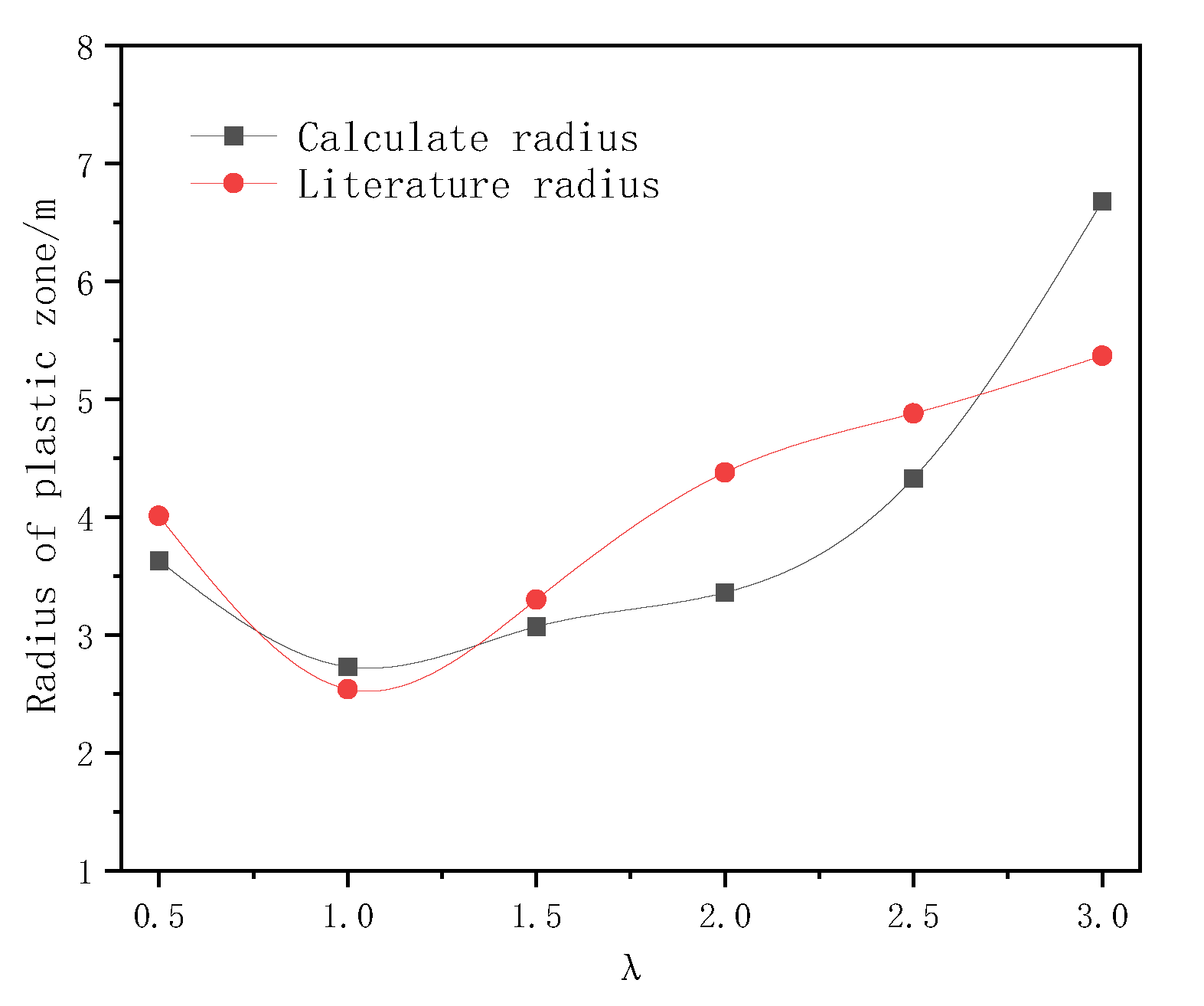
A comparison between the Xinjiang Bulunkou tunnel, affected by high geothermal temperature and geostress, and the theoretical outcomes of this study reveals a significant difference in the radius of the surrounding rock’s plastic zone and the stress induced by thermal interaction. This emphasizes the considerable role of thermal stress in influencing the plastic zone, validating its substantial impact.

Author Contributions

Conceptualization, H.J. and Y.Y.; data curation, Y.Y.; formal analysis, Y.Y.; funding acquisition, H.J. and Q.L.; investigation, H.J., Y.Y., and Q.L.; methodology, H.J., Y.Y. and Q.L.; project administration, H.J. and Q.L.; resources, H.J. and Q.L.; software, Y.Y.; supervision, H.J., J.Z., G.L., and Q.L.; validation, Y.Y.; visualization, Y.Y.; writing—original draft, H.J., Y.Y., and Q.L.; writing—review and editing, Y.Y., H.J., J.Z., G.L., and Q.L. All authors have read and agreed to the published version of the manuscript.

Funding

This study was supported by the National Natural Science Foundation of China (52369021) and the Youth Fund of the National Natural Science Foundation of China (42102312).

Institutional Review Board Statement

Not applicable.

Informed Consent Statement

Not applicable.

Data Availability Statement

Data is contained within the article.

Conflicts of Interest

Author Jun Zhang as employed by the company Xinjiang Water Resources and Hydropower Survey Design and Research Institute Limited Liability Company. The remaining authors declare that the research was conducted in the absence of any commercial or financial relationships that could be construed as a potential conflict of interest.

References

  1. Song, Y.; Gao, Y.S.; J, G.C.; Teng, J.; Liu, K.H. Engineering Geologic Study of Deeply Buried Long Tunnels in Water Conservancy and Hydropower Projects; China Water Resources and Hydropower Press: Beijing, China, 2014. [Google Scholar]
  2. Ma, N.J.; Zhao, X.D.; Zhao, Z.Q.; Li, J.; Guo, X.F. Stability analysis and control technology of mine roadway roof in deep mining. J. China Coal Soc. 2015, 40, 2287–2295. [Google Scholar] [CrossRef]
  3. Wu, J.; Dong, Y.; Jiang, Y.; Yang, Y.; Sun, H.; Yin, D.; Gu, W. Research on plastic zone evolution law of surrounding rock of gob-side entry retaining under typical roof conditions in deep mine. Shock. Vib. 2020, 2020, 8864991. [Google Scholar] [CrossRef]
  4. Zheng, Y.R.; Zhu, H.H.; Fang, Z.C.; Liu, H.H. Stability Analysis and Design Theory of Underground Engineering Surrounding Rock; People’s Transportation Press: Beijing, China, 2012; pp. 17–21. [Google Scholar]
  5. Zhao, Z.Q. Mechanism of Surrounding Rock Deformation and Failure and Control Method Research in Large Deformation Mining Roadway; China University of Mining and Technology: Beijing, China, 2014. [Google Scholar]
  6. Chen, L.W.; Peng, J.B.; Fan, W.; Sun, P. Analysis of surrounding rock mass plastic zone of round tunnel under non-uniform stress field based on the unified strength theory. J. China Coal Soc. 2007, 32, 20–23. [Google Scholar]
  7. Zhang, X.B.; Zhao, G.M.; Meng, X.R. Analysis of plastic zone of circular roadway perimeter rock in non-uniform stress field based on nonlinear uniform strength criterion of rock. J. Saf. Environ. 2013, 13, 202–206. [Google Scholar]
  8. Guo, X.F.; Ma, N.J.; Z, X.D.; Zhao, Z.Q.; Li, Y.E. General morphology of plastic zone of circular roadway perimeter rock and its determination criterion. J. Coal 2016, 41, 1871–1877. [Google Scholar]
  9. Ma, N.J.; Li, J.; Zhao, Z.Q. Research on the distribution law of deviatoric stress field and plastic zone in the surrounding rock of circular roadway. J. China Univ. Min. Technol. 2015, 44, 206–213. [Google Scholar]
  10. Wang, W.J.; Guo, G.Y.; Zhu, Y.J.; Yu, W.J. Malignant extension process and its control of plastic zone of surrounding rock in high stress soft rock roadway. J. Coal 2015, 40, 2747–2754. [Google Scholar]
  11. He, M.C. Current status of rock mechanics in deep mining engineering and its prospect. In Proceedings of the Eighth National Conference on Rock Mechanics and Engineering; Chinese Society of Rock Mechanics and Engineering; Science Press: Beijing, China, 2004; Volume 7. [Google Scholar]
  12. Meng, W.; He, C.; Wu, F.Y.; Chen, Z.Q.; Zhou, Z.H.; Kou, H. Influence of thermal stresses on rockburst prediction in rocks spawned by geothermal gradients. J. Southwest Jiaotong Univ. 2022, 57, 903–909. [Google Scholar]
  13. Li, T.B.; Pan, H.S.; Chen, G.Q.; Meng, L.B. Physical modelling test of temperature effect of tunnel rockburst under heat-force. J. Rock Mech. Eng. 2018, 37, 261–273. [Google Scholar]
  14. Yan, J.; He, C.; Bo, W.; Meng, W.; Wu, F.Y. Rockburst prognosis and characteristics of deeply buried long tunnel complexes in the Yarlung Tsangpo River suture zone. J. Rock Mech. Eng. 2019, 38, 769–781. [Google Scholar]
  15. Xu, L.S.; Tang, B.M.; Mu, C.C.; Yang, J.; Meng, H. Current Research Situation of Problems Related to High Ground Stress and Rock Blasting. Technocogy Highw. Transp. 2002, 4, 48–51. [Google Scholar]
  16. Sun, Y. A review of geostress and its application in mining engineering. West-China Explor. Eng. 2017, 29, 127–129 + 134. [Google Scholar]
  17. Du, S.J.; Liu, H.; Zhi, H.T.; Chen, H.H. Testing study on mechanical properties of post-high-temperature granite. Chin. J. Rock Mech. Eng. 2004, 14, 2359–2364. [Google Scholar]
  18. Guo, X.F.; Guo, L.F.; Ma, N.J.; Zhao, Z.Q.; Li, C. Applicability analysis of the roadway butterfly failure theory. J. China Univ. Min. 2020, 49, 646–653 + 660. [Google Scholar] [CrossRef]
  19. Hao, Z.; Sun, G.Z. Research on the morphological characteristics and evolution law of plasticity zone in the roadway of back mining of extra-thick coal seam. Coal Sci. Technol. 2022, 50, 77–83. [Google Scholar] [CrossRef]
  20. Cai, M.F.; He, M.C.; Liu, D.Y. Rock Mechanics and Engineering, 2nd ed.; Science Press: Beijing, China, 2013. [Google Scholar]
Figure 1. The variation law of principal stress and temperature with the depth of tunnel drilling.
Applsci 14 07589 g001
Figure 2. Mechanical model of circular tunnel considering thermal stress of rock mass.
Applsci 14 07589 g002
Figure 3. Morphology evolution of tunnel plastic zone when lateral pressure coefficient changes.
Applsci 14 07589 g003
Figure 4. Morphology evolution of tunnel plastic zone when thermal stress of rock mass changes.
Applsci 14 07589 g004
Figure 5. Morphology evolution of plastic zone when lateral pressure coefficient of tunnel with high ground temperature changes (T = 80 °C, σT = 3.78 MPa).
Applsci 14 07589 g005
Figure 6. Changes in plastic zone radius with lateral coefficient when thermal stress of rock mass is considered (T = 80 °C, σT = 3.78 MPa).
Applsci 14 07589 g006
Figure 7. Morphology evolution of plastic zone under temperature change of high ground stress tunnel (λ = 2.8).
Applsci 14 07589 g007
Figure 8. Comparison of the maximum radius value of the plastic zone of the tunnel when the temperature changes.
Applsci 14 07589 g008
Figure 9. K value curve when the temperature changes.
Applsci 14 07589 g009
Figure 10. Comparison of plastic zone radius when polar angle changes (λ = 2.8).
Applsci 14 07589 g010
Figure 11. Comparison of theoretical and monitored values of peripheral rock stress under different lateral pressure coefficients.
Applsci 14 07589 g011
Figure 12. Comparison of theoretical and monitored values of horizontal principal stresses in the surrounding rock with different lateral pressure coefficients.
Applsci 14 07589 g012
Figure 13. Comparison of theoretical values of plastic zone radius with those in the literature [20] under different lateral pressure coefficients (unit: m).
Applsci 14 07589 g013
Table 1. Site borehole layout.
Drill Hole NumberAltitude/mDrilling DirectionNumber of Measurement Points
Tilt/°Azimuth/°
YBK13340−5813
YBK23341−4533
YBK33342−5973
Table 2. Test results of drill hole hydraulic fracturing method.
Drill Hole NumberMeasurement
Point
Surrounding Rock
Temperature T/°C
Profundity H/mσH/MPaσh/MPaσz/MPaλ
YBK1172.48.220.010.215.11.3
278.712.022.212.015.21.5
387.516.624.712.715.31.6
491.319.626.213.215.41.7
595.723.326.513.215.51.7
YBK2173.48.419.910.315.11.3
278.412.621.611.015.21.4
385.315.923.111.915.31.5
491.319.626.412.915.41.7
595.323.927.113.115.51.8
YBK3174.18.620.910.515.11.3
278.712.722.611.215.21.4
384.816.223.512.215.31.5
491.619.726.412.815.41.7
595.723.527.813.515.51.9
Note: The dead weight stress is calculated according to the bulk weight of the rock, which is 26.5 kN/m3, and the hole buried depth is 560 m.
Table 3. Mechanical parameters of tunnel envelope.
Modulus of Elasticity
E/Gpa
Poisson’s Ratio
μ
Cohesive Force
C/Mpa
Angle of Internal Friction
ψ/°
Coefficient of Linear Expansion of Surrounding Rock
β/°C−1
60.250.9300.000005
Table 4. Table of results for stress components.
Measurement Point
Number
Depth of Measurement
Point/m
σXσYσZσXYσYZσZX
/MPa
SYZK1-113.321.920.915.6−5.50.50.1
SYZK1-214.522.422.914.9−7.10.8−0.3
SYZK1-315.122.419.815.3−7.30.51.1
SYZK1-416.325.022.015.3−8.71.1−1.1
SYZK2-113.920.516.715.7−7.11.0−1.1
SYZK2-214.521.318.515.2−8.81.3−1.5
SYZK3-113.021.016.515.4−12.03.9−2.0
SYZK3-213.517.621.614.8−12.3−0.81.4
SYZK3-314.019.121.914.6−11.91.1−1.4
Note: The X-axis is due north, the Y-axis is due west, and the Z-axis is vertically upward in a right-handed system.
Table 5. Magnitude and direction of horizontal principal stresses.
Measurement
Point Number
σH/MPaσh/MPaσZ/MPaλ = σHZ
SYZK1-126.915.915.61.7
SYZK1-229.815.514.92.0
SYZK1-328.613.715.31.9
SYZK1-432.414.715.32.1
SYZK2-126.011.215.71.7
SYZK2-228.710.815.21.9
SYZK3-131.06.515.42.0
SYZK3-232.17.114.82.2
SYZK3-332.48.514.62.2
Disclaimer/Publisher’s Note: The statements, opinions and data contained in all publications are solely those of the individual author(s) and contributor(s) and not of MDPI and/or the editor(s). MDPI and/or the editor(s) disclaim responsibility for any injury to people or property resulting from any ideas, methods, instructions or products referred to in the content.

