Abstract
Traditional range–instantaneous Doppler (RID) methods for maneuvering target imaging are hindered by issues related to low resolution and inadequate noise suppression. To address this, we propose a novel ISAR imaging method enhanced by deep learning, which incorporates the fundamental architecture of CapsNet along with two additional convolutional layers. Pre-training is conducted through the deep learning network to establish the mapping function for reference. Subsequently, the trained network is integrated into the electromagnetic simulation software, Feko 2019, utilizing a combination of geometric forms such as corner reflectors and Luneberg spheres for analysis. The results indicate that the derived ISAR imaging effectively identifies the ISAR program associated with complex aerial targets. A thorough analysis of the imaging results further corroborates the effectiveness and superiority of this approach. Both simulation and empirical data demonstrate that this method significantly enhances imaging resolution and noise suppression.
1. Introduction
Radar target recognition technology is one of the most significant research directions in the development of modern radar systems [1]. Over the past few decades, numerous pioneering accomplishments have been achieved in both theoretical research and engineering applications. The key areas of radar target recognition, such as the theoretical analysis of the electromagnetic scattering mechanism of radar targets, the description and feature extraction of target scattering characteristics, and pattern recognition technology, have been thoroughly investigated [2,3,4]. With the advancement of radar technology, serving as the foundation of current synthetic aperture radar (SAR) and inverse synthetic aperture radar (ISAR) imaging, the combination of high radial range resolution resulting from wide bands and high lateral range resolution brought about by high Doppler resolution generates a two-dimensional scattering image of the target, providing more abundant and detailed information about a target. It enables location, orientation, shape, and structure of the target to be determined, which can be utilized for classification and recognition [5,6,7,8]. Consequently, target scattering feature extraction based on the two-dimensional image of radar targets has emerged as an effective approach for obtaining target features in complex electromagnetic environments.
Analyzing the scattering characteristics of three-dimensional electrically large and complex targets is a highly challenging research task [9]. In recent years, many advanced electromagnetic field calculation methods, such as the physical optics method, geometric optics method, physical diffraction theory, geometric diffraction theory, and equivalent edge electromagnetic current method, have been widely utilized in academic circles [10]. The theoretical modeling of complex objects typically employs numerous approaches, such as three-dimensional reconstruction, component decomposition, and the surface element method. However, for three-dimensional electrically large and complex objects, the performance of algorithms is often limited when relying solely on a single electromagnetic field calculation method. Consequently, when addressing different types of targets, some researchers flexibly combine various methods for calculations, taking into account the differences in the physical characteristics of their scattering centers. In view of the substantial differences between the basic theory and practical engineering modeling, some experts tend to employ the component decomposition method to simplify complex objects into standard and regular geometric structures (such as corner reflectors, plates, etc.) for more precise approximate analysis [11].
In recent years, the rapid advancement of deep learning has led to the employment of specially designed neural networks for various radar imaging applications. The deep convolutional neural network (CNN) [12] is utilized to suppress the sidelobes of ISAR images. Neural networks, particularly deep neural networks, typically require substantial amounts of data. To address the challenge of insufficient training data, simulated data are employed, with target images obtained through traditional range–Doppler (RD) processing being input into the model. The ISAR images generated from the ideal point model serve as a reference. A Complex CNN (Complex CNN, CCNN) was proposed in [12] due to the inherent complexity of radar data. Deep neural networks have also been applied to SAR imaging in the presence of motion errors [13], where SAR imaging is framed as a sparse recovery problem [13] and resolved by unfolding the neural network. The deep network is subsequently retrained using simulated data. Experimental results demonstrate that the learned model is effectively transferable from simulated data to the application of actual radar data.
This study builds upon our previous research [14]. In this paper, we introduce several significant enhancements and expansions. Compared with the research presented in [14], this study further addresses the practical challenges of super-resolution and noise suppression, designing a CapsNet that incorporates two convolution types—AKConv and GSConv—with the objective of generating and denoising ISAR images. Additionally, this paper investigates the robustness of the proposed algorithm against noise.
The remainder of this paper is structured as follows: Section 3 provides a detailed explanation of our proposed CapsNet-assisted ISAR imaging method for maneuvering targets, including an in-depth description of the neural network architecture, the introduction of the two novel convolution kernels, the generation of training data, and the network training process. In Section 4, we conduct numerical experiments to validate the effectiveness of the proposed method, making comparisons with other existing algorithms using simulation and several sets of real radar data. Finally, conclusions are presented in Section 5.
2. ISAR Model
2.1. Principles of Electromagnetic Analysis
In the study of scattering characteristics of complex air targets, the scattering center refers to the region on the target that produces the main scattering effect on electromagnetic waves [15]. Key elements for describing the scattering center include its position, amplitude and geometric type. These elements are essential for accurately understanding and predicting the scattering behavior of a target. Currently, methods for determining the scattering center are mainly divided into two categories: non-parametric methods and parametric methods. The non-parametric method primarily relies on Fourier analysis, which extracts relevant information about the scattering center by analyzing the spectral characteristics of the target’s scattered signal. This method does not require a predefined model of the scattering center; rather, it identifies the existence and characteristics of the scattering center through data analysis. In contrast, the parameter method is a model-based parameter estimation technique that typically necessitates defining the scattering center model in advance. It estimates the model parameters through optimization algorithms to ascertain the location, amplitude and geometric type of the scattering center. While this approach generally demands more prior knowledge and computational resources, it offers the advantage of providing a more accurate description of the scattering center.
Through theoretical calculation and experimental verification, the total electromagnetic scattering of complex targets can be attributed to a series of local scattering sources. These local scattering sources, known as equivalent multiple scattering centers (EMscs), are one of the core elements of a target’s scattering characteristics. The translational component is that the target attitude remains unchanged relative to the radar ray, while the rotational component is that the target rotates around a certain reference point. By compensating for the translational component, the target can be equivalent to a planar turntable model, and then the two-dimensional image of the target can be obtained by using the Doppler effect and signal processing techniques.
The plane wave takes the frequency as the irradiation target and the incidence angle as the irradiation target. The expression of the function that defines the two-dimensional scattering image of the target is as follows:
where: —backscattered electric field,
—incident electric field;
—Distance from radar to target
—beam,
represents the two-dimensional scattering center distribution of the target, i.e., the two-dimensional scattering image, which is not only about the coordinate relationship of , but also includes the function of radar frequency and incidence angle . The scattering characteristics can be equivalently regarded as the vector superposition of the backward scattering from scattering centers:
where is the backscatter intensity of the th scattering center, and is twice the time delay from the i th scattering center to the rotation center , namely:
Substitute the above formula into Formula (2) to obtain the following:
where , .
Formula (4) is the scattering echo model constructed by the two-dimensional scattering center of the radar target on the plane, which is also the basic scattering model of radar ISAR imaging.
2.2. ISAR Signal Model
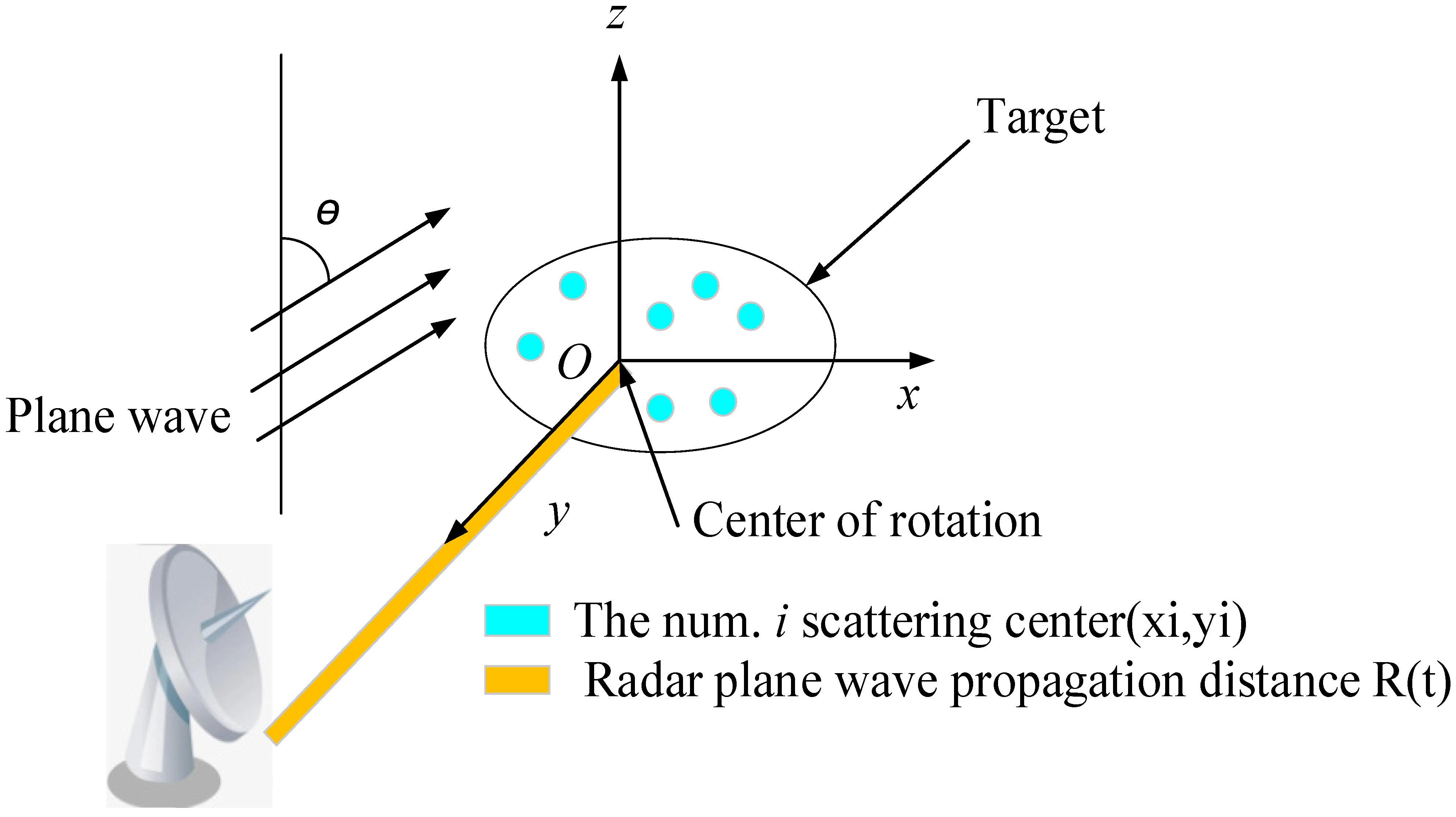
Inverse synthetic aperture radar (ISAR) is a method for acquiring two-dimensional images of targets using signal processing technology, which is widely employed in target detection and recognition, as illustrated in Figure 1. The ISAR imaging results for a target can be obtained by analyzing the reflection cross-section data with respect to frequency and orientation. Specifically, the longitudinal distance (down-range) refers to the distance along the axis that is parallel to the incident direction, and achieving longitudinal distance imaging necessitates the use of broadband scattering field data. The cross-range, on the other hand, is the axis that is perpendicular to the longitudinal distance, which can be simulated by processing the scattered field data obtained from various angles.

Figure 1.
The spatial relationship between radar and target imaging.
For the scattering field data of the target in a small frequency band and a small azimuth angle, that is, if is satisfied, the corresponding ISAR imaging can be obtained by using two-dimensional inverse Fourier transform (IFT). The RCS scattering field of the target is defined as , and then is as follows:
where , , and are the space coordinates; is the frequency; is the wave number; and is the wave number corresponding to the center frequency.
3. CapsNet Assists ISAR Imaging
In this section, a radar ISAR imaging system based on CapsNet is proposed to address the low-resolution issue of the traditional linear TFA.
3.1. A Radar ISAR Imaging System Based on CapsNet
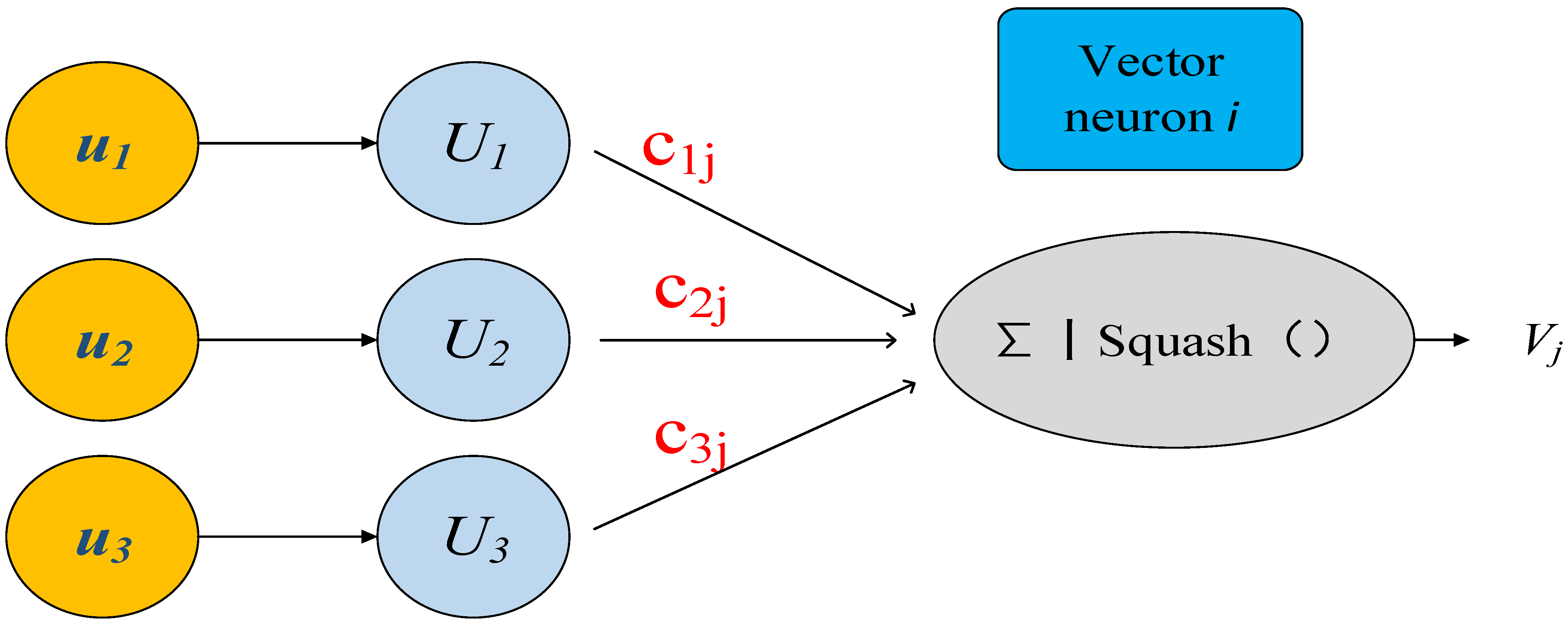
In 2011, Hinton put forward the concept of a capsule [16]. Distinct from the traditional scalar neurons, the capsule network constitutes a vector composed of numerous neurons. The vector length of the capsule neuron model indicates the probability of the existence of the target passed by the upper network, and its direction represents the actual state of the entity, namely, “Instance parameters”, as depicted in Figure 2 [17].

Figure 2.
Capsule neuron model.
The dynamic routing algorithm (squash) solves the problem by the output value of the capsule.
The updated formula is as follows:
where is the dynamic routing coupling coefficient, and is the number of initial similarity weights .
The capsule output is obtained from the lower-level capsule inputs and :
where is derived from , is the weight of the capsule network.
The output should be expressed as a probability. Thus, the output value should be controlled for (0, 1], and can be obtained using nonlinear compression:
The image is initially input into the convolutional layer, where a basic capsule layer is generated through the convolution operation. Subsequently, the data from the basic capsule layer are transmitted to the image via the dynamic routing algorithm (squash). The capsule layer then transfers the data from the image capsule layer to the feature capsule layer. Finally, a fully connected layer is employed to reorganize and model the data from the feature capsule layer. The structure of the CapsNet is illustrated in Figure 3.
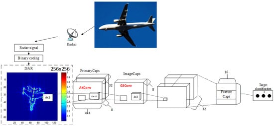
Figure 3.
Schematic diagram of the CapsNetv2 structure.
The contraction path comprises two convolutional layers: AKconv and GSconv. A max-pooling operation with a stride of 2 is employed to down-sample the feature map. Consequently, the number of feature channels is doubled, while the size of each layer’s features is halved. The expansion path consists of up-sampling layers and convolutional layers, where the convolutional layers halve the number of feature channels and double the size of the features.
- AKconv
AKconv, or Alterable Kernel Convolution, is a convolution operation employed in convolutional neural networks, with the aim of addressing the inherent deficiencies in traditional convolutions. AKconv enables the arbitrary setting of convolution kernel parameters, and its size and shape can be freely adjusted in accordance with specific application requirements, thereby more accurately adapting to the target features of different scales. It introduces an innovative algorithm for determining the initial sampling positions for convolution kernels of various sizes, enhancing the adaptability of the network in handling targets of different sizes. It also adopts dynamic offset technology to adjust the sampling positions, achieving more accurate feature capture.
- b.
- GSconv
GSconv (Grouped Spatial Convolution) is a convolution operation in convolutional neural networks that aims to tackle the inherent deficiencies of traditional convolutions. GSconv allows for the arbitrary setting of convolution kernel parameters and can freely adjust its size and shape in accordance with specific application requirements to adapt more accurately to the target features of different scales. It introduces an innovative algorithm for determining the initial sampling positions of convolution kernels of various sizes, enhancing the adaptability of the network in handling targets of different sizes. To deal with the diversity of target shapes, GSconv employs dynamic offset technology to adjust the sampling positions to achieve more accurate feature capture.
3.2. Training of the CapsNet
Regarding the whole structure of the CapsNet, in this section, we discuss its training processing, including the generation of its input and reference. The inputs of the network area series of STFT spectra of the simulated radar signals are generated according to (5), and the number of scatterers is randomly selected from 1 to 5. To consider the noise effect, random Gaussian noise is added to the simulated signals with a signal-to-noise ratio (SNR) changing from 5 to 10 dB. STFT spectra of the simulated signals are computed according to (9) as the input of the network. In our setting, the input image is of size and the reference image is expected to be of since two times up-sampling operations are implemented in the proposed network. The reference image is generated according to (9).
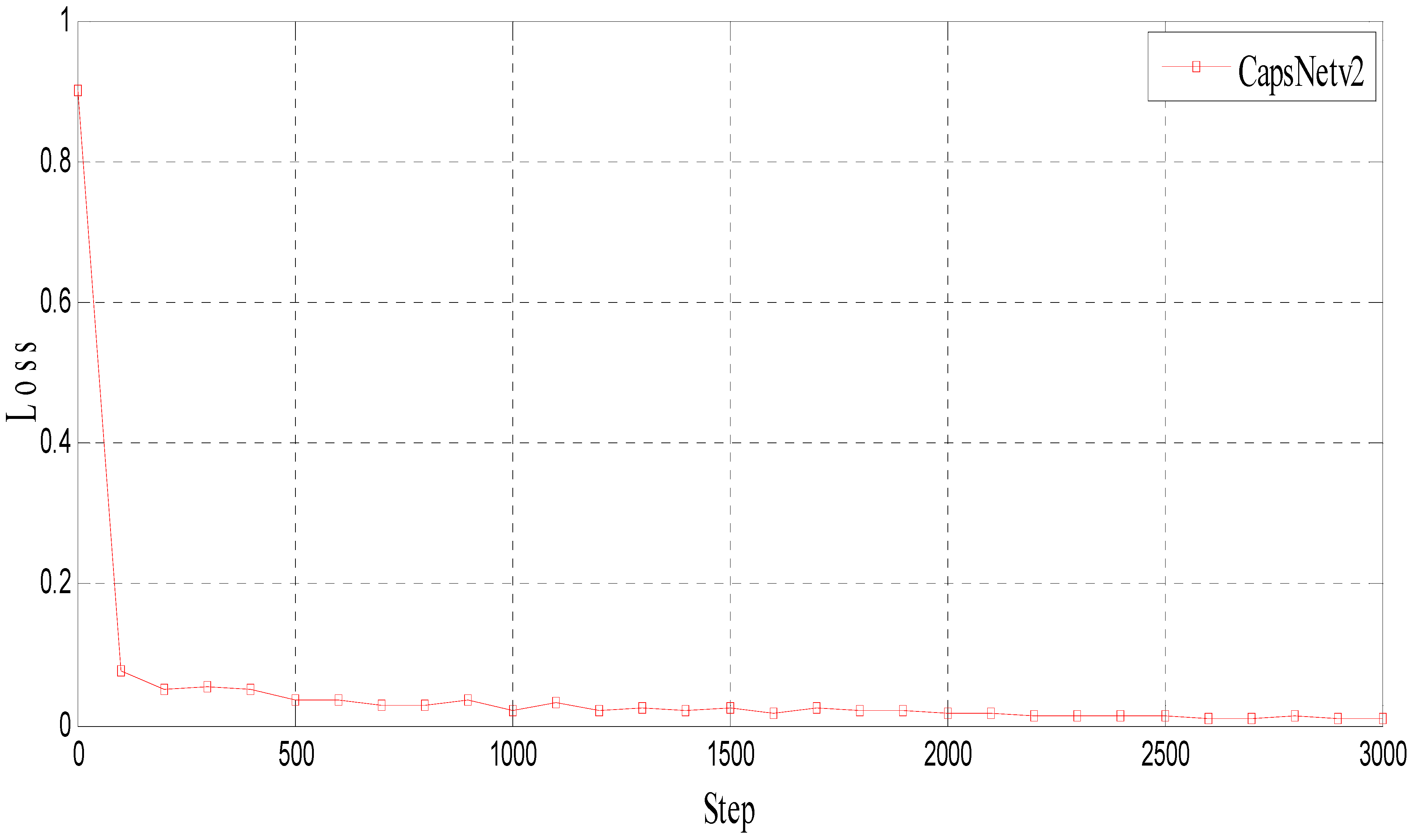
The network is trained to approximate the function, which can transform the noisy low-resolution spectral image to a noiseless ideal image with a high resolution. After training, the loss results of CapsNet are shown in Figure 4. The parameter settings of CapsNet are summarized in Table 1.
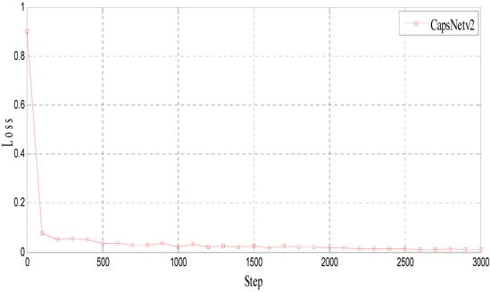
Figure 4.
The loss of CapsNet.

Table 1.
Training parameters.
4. Analysis of Simulation Results and Experimental Results
4.1. Simulation Results
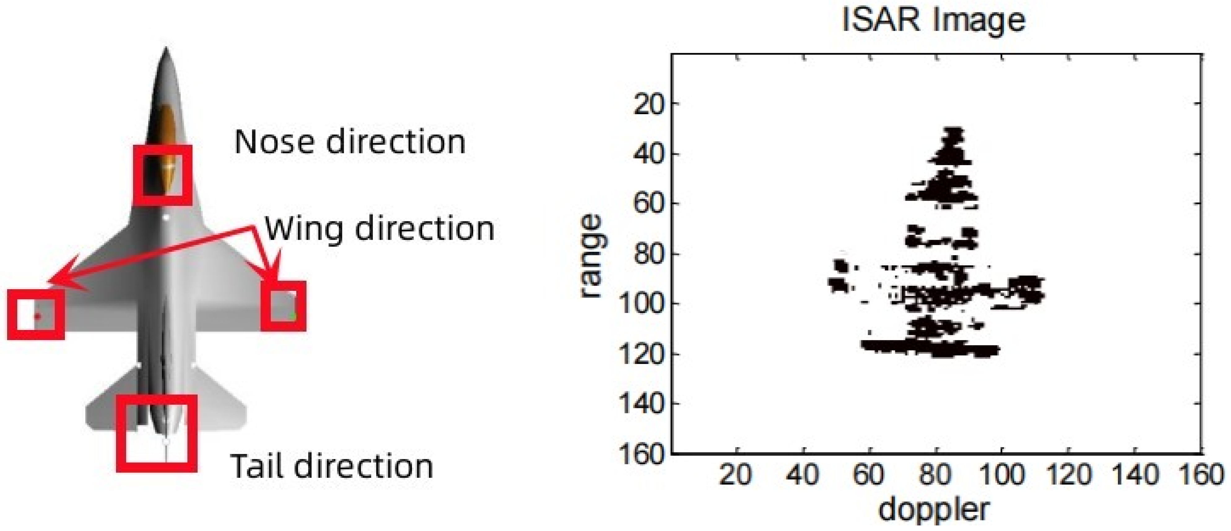
The RCS spatial distribution characteristics of complex air targets exhibit the following features: (1) a high RCS value within a narrow airspace; (2) a low RCS value with certain fluctuations across a wide airspace range. Furthermore, due to the aircraft’s complex structure and the presence of multiple scattering centers, the different incidence angles of the radar will lead to great changes in the spatial distribution characteristics of the aircraft RCS, as shown in Figure 5 [18]. For complex air targets, the scattering centers consist of scatterers with simple geometric structures, such as plates, points, edges, angles, etc. Consequently, complex air targets can be represented as a vector superposition of backscatter from several typical feature directions. The maximum RCS values for these typical feature directions of complex air targets, along with the corresponding contribution positions, are presented in Table 2 [19]. Therefore, this paper proposes a simulation scheme focusing on three typical characteristics of complex air targets: the nose, wing and tail directions.

Figure 5.
ISAR imaging of an aircraft.
Table 2.
Maximum RCS values and contribution positions of typical characteristic directions of complex air targets.
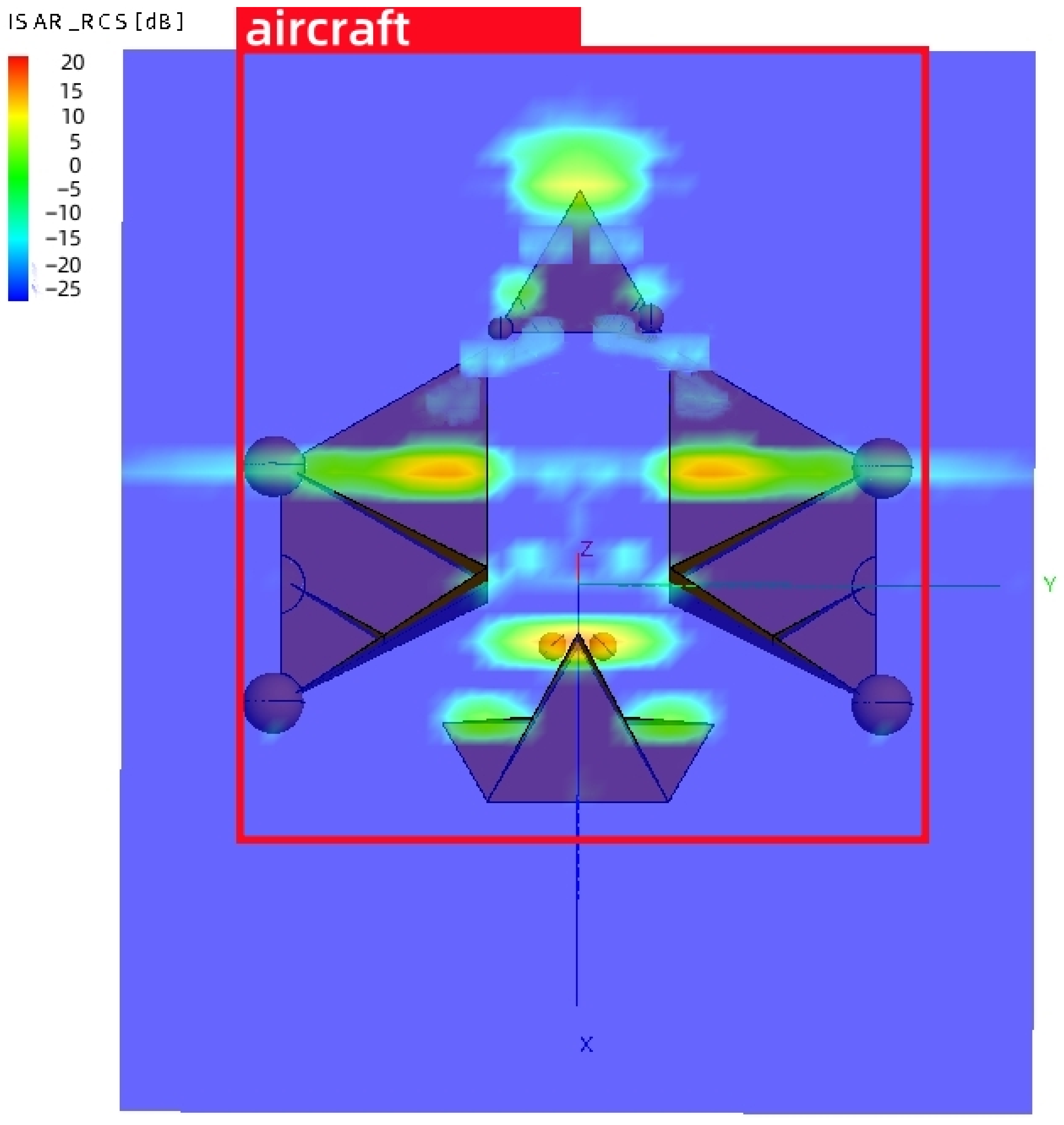
The structure diagram illustrating the simulated assembly of each part of the aircraft is presented in Figure 6. A 60° corner reflector with a side length of 0.6 m, two 60° corner reflectors with a side length of 0.3 m and two Luneberg lens reflector with a radius of 40 mm can be used as the best design scheme for the typical features of the head in Figure 6a, a combination of four 60° corner reflectors with a side length of 0.78 m, two metal balls with a diameter of 200 mm, and a flapper with an offset of 50 mm can be used as the best design solution for the typical features of the wing, a 60° variable corner reflector with a side length of 0.54 m, a metal ball diameter of 80 mm at the top of the left corner reflector, 88 mm at the right reflector and a Luneberg lens reflector diameter of 80 mm are used as the best design scheme for the typical features of the tail.
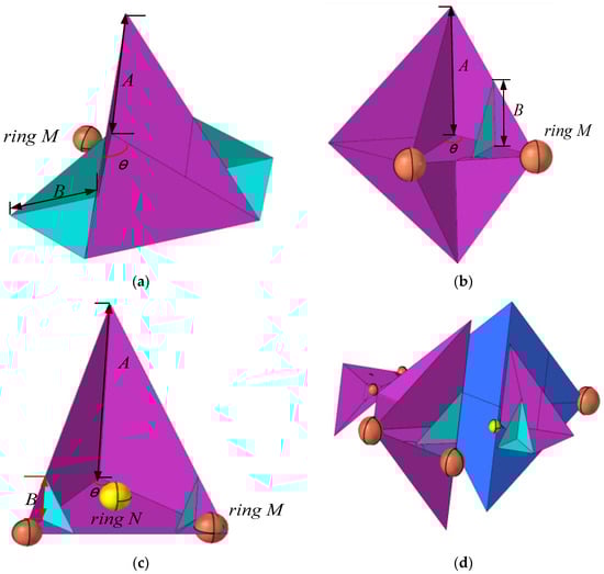
Figure 6.
The structure diagram of the simulation assembly of each part of the aircraft. (a) Typical head orientation. (b) Typical wing simulation. (c) Typical tail orientation. (d) Aircraft omnidirectional simulation.
In this paper, the FEKO 2019 is applied to calculate the far-field RCS distribution characteristics of the target. FEKO is a software program for electromagnetic calculation and electromagnetic field analysis, which is widely used in electromagnetic scattering simulation. FEKO has numerous solvers, and the solvers can be selected according to specific simulation requirements. FEKO integrates many methods of electromagnetic numerical calculation, including the Method of Moments (MOM), the Fast Multipole Method (MLFMM), the Ray Tracing Geometrical Optics Method (RL-GO), the Physical Optics Method (PO), the Geometrical Optics Method (GO), the Geometrical Theory of Diffraction (UTD), and the Finite Element Method (FEM).
The main steps to solve the RCS distribution characteristics using FEKO are as follows:
(1) Model establishment. CADFEKO has the function of establishing geometric models. After modeling the model, as shown in Figure 6d, it is imported into FEKO.
(2) The relevant parameters, such as the incident wave frequency, angle, phase, polarization mode, and single-station working mode, are set, and then the far-field RCS solver is added. The specific set parameters are shown in Table 3.
Table 3.
FEKO solver parameter settings.
(3) Select the appropriate algorithm. Since the model in this paper belongs to an electrically large-sized target, the calculation time using the traditional MOM method is too long and the requirements for the computer configuration are relatively high. Therefore, in this paper, the high-frequency approximation method RL-GO is selected to solve the target RCS to shorten the calculation time.
(4) Mesh the model. The scale of mesh division is generally one-tenth of the wavelength. For the high-frequency approximation method, the division scale can be appropriately increased. In this paper, triangular mesh division is selected, and the number of divided meshes is 1753.
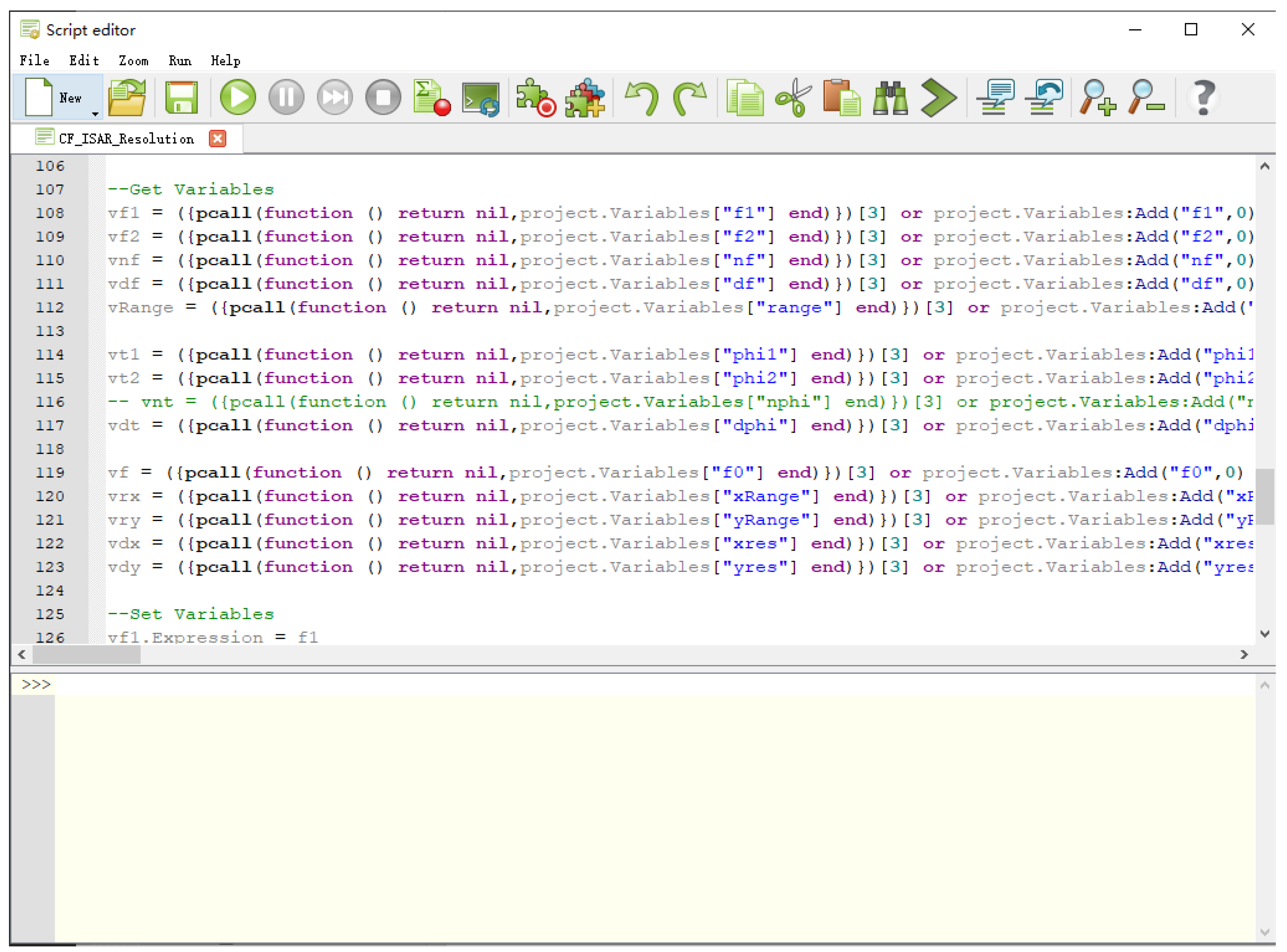
(5) The script for importing the ISAR imaging calculation method in Equation (5) into FEKO is shown in Figure 7. Then, the calculation is performed and POSTFEKO is opened to display the ISAR imaging results. The ISAR imaging results are placed in the prediction set of CapsNet, and finally, the target recognition results can be obtained as shown in Figure 8.
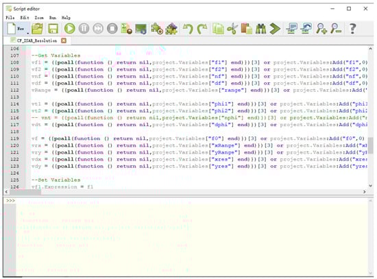
Figure 7.
Set up the ISAR imaging script in FEKO.
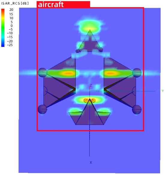
Figure 8.
Recognition results of the aircraft simulation ISAR imaging.
As can be seen from Figure 8, a radar ISAR imaging system based on CapsNet, as proposed in this paper, can accurately identify aircraft ISAR imaging.
4.2. Measurement Results
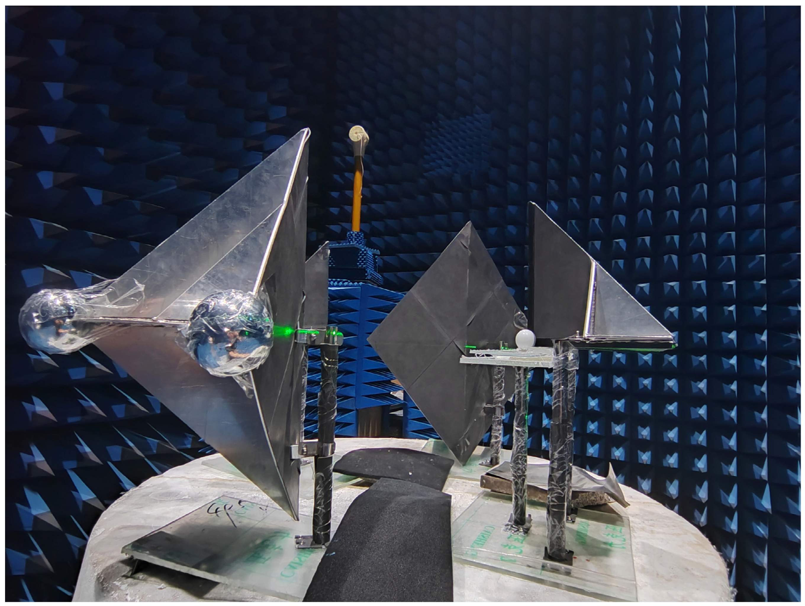
In order to verify this design, this paper made a microwave anechoic chamber measurement experiment model. A microwave anechoic chamber refers to a space where the majority of incident electromagnetic waves are absorbed when they reach the walls, ceiling, and floor, with very little transmission or reflection. Microwaves share certain characteristics with light. Borrowing this concept from optical darkrooms, a microwave anechoic chamber can be created. A microwave anechoic chamber uses absorbing materials to create an enclosed space, thereby creating a pure electromagnetic environment within the chamber. The main working principle of a microwave anechoic chamber is based on the law that electromagnetic waves propagate from a low magnetic permeability to a high magnetic permeability in a medium. High-permeability absorbing materials are utilized to guide the electromagnetic waves. Through resonance, a large amount of the radiated energy of the electromagnetic waves is absorbed, and then the energy of the electromagnetic waves is transformed into heat energy through coupling. The angular reflection material in the model was aluminum with a thickness of 3 mm, which was assembled by welding process. The lower support base was made of acrylic wave-transmitting material, and the back was pasted with wave-absorbing material. The photo of the object is shown in Figure 9.
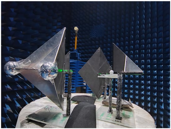
Figure 9.
Physical model of aircraft simulation assembly.
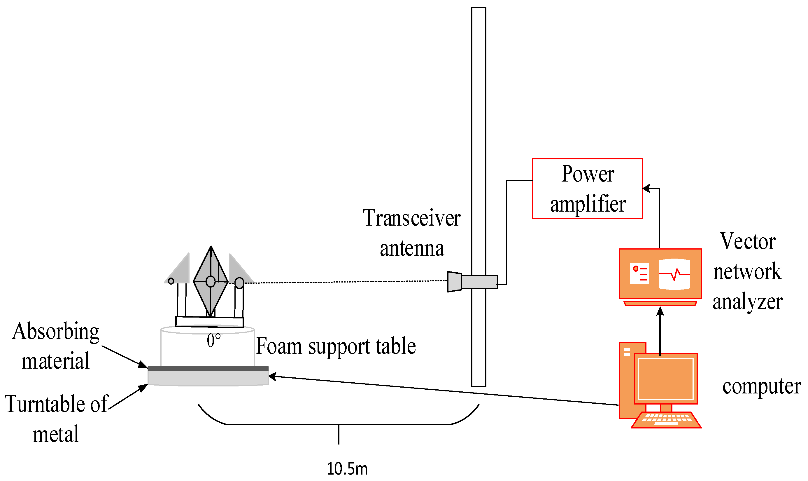
The test system, illustrated in Figure 10, primarily comprises a computer (which includes test control and data processing software), a vector network analyzer, a power amplifier, a transceiver antenna, a turntable controller, a turntable, and a support structure. To enhance measurement accuracy, time gating technology is employed. The two antennas are positioned side by side and perpendicular to the target, facilitating the measurement of the RCS distribution characteristics under far-field conditions, as well as the data required for ISAR imaging. The specific test parameters are detailed in Table 4.

Figure 10.
Test system.
Table 4.
Test parameter.
As shown in the ISAR imaging model in Figure 1 that after translational motion compensation, no matter what kind of non-stationary and complex motion the ISAR conducts, the maneuvering target can still be equivalent to a turntable imaging model that rotates around the reference center O. If it is assumed that the reference origin O is consistent with the self-focusing center of the ISAR target, and the two-dimensional imaging projection plane is perpendicular to the rotation axis, when the maneuvering target conducts non-stationary motion, the angle rotated by the ISAR target within the same time interval is a non-constant variable parameter, which leads to different Doppler frequency values generated by each scattering point of the target during the rotation process.
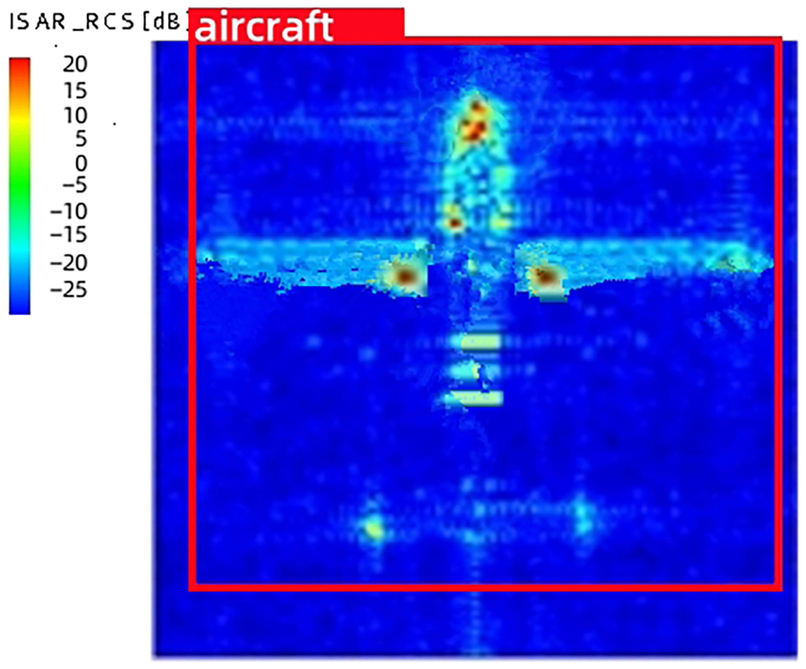
When the target has a stable motion, since the turntable works in a uniform rotation mode, the Doppler frequency of each scattering point is proportional to the azimuth coordinate x value. When sampling at equal intervals, the angle rotated by each scattering point remains constant. Therefore, the azimuth imaging processing process can be directly achieved by separating these Doppler frequencies in the frequency domain. Then, performing DFT transformation on the echo signal can obtain the two-dimensional imaging of the target, which is the ISAR imaging result. Finally, the imaging result is placed in the prediction set of CapsNet for recognition, and the final recognition result is shown in Figure 11.

Figure 11.
Recognition results of the aircraft ISAR imaging.
As illustrated in Figure 11, it can be seen that the radar ISAR imaging system based on CapsNet proposed in this paper can accurately recognize aircraft simulation assembly as a two-dimensional scattering image of the aircraft. The experimental results corroborate the efficacy of the radar ISAR imaging system utilizing CapsNet.
5. Conclusions
To achieve super-resolution ISAR images for maneuvering targets, a novel ISAR imaging method based on deep learning assistance is proposed. The neural network integrates the structure of CapsNet and is trained on samples to learn the inherent mapping function. The trained CapsNet effectively suppresses background noise. Numerical experimental results demonstrate the effectiveness of the proposed method. A novel composite structure based on a corner reflector, Luneberg lens reflector sphere plate, and array technology is proposed. The ISAR image formed through this combination is widely recognized as the aircraft target, which proves that the combination method can effectively simulate the ISAR image result of the aircraft target.
Author Contributions
Conceptualization, Y.W.; methodology, J.H.; investigation, S.Y.; formal analysis, H.G.; software, J.H. All authors have read and agreed to the published version of the manuscript.
Funding
This research was funded by (Ministry of Education of the People’s Republic of China grant) number [20190209400011].
Institutional Review Board Statement
Not applicable.
Informed Consent Statement
Not applicable.
Data Availability Statement
The original contributions presented in the study are included in the article, further inquiries can be directed to the corresponding author.
Conflicts of Interest
The authors declare no conflict of interest.
References
- Zhang, H.H. Adaptive Neighborhood-Preserving Discriminant Projection Method for HRRP-Based Radar Target Recognition. IEEE Antennas Wirel. Propag. Lett. 2014, 1, 1–3. [Google Scholar] [CrossRef]
- Chou, H.T.; Chang, T. Indoor Experimental Setup for Radar Antenna Characterization by Placing a Reference Target at the Focus of Compact Range Reflector. IEEE Trans. Antennas Propag. 2023, 71, 7860–7869. [Google Scholar] [CrossRef]
- Kong, D.H.; Zhang, W.W. Intelligent Prediction for Scattering Properties Based on Multihead Attention and Target Inherent Feature Parameter. IEEE Trans. Antennas Propag. 2023, 71, 5504–5509. [Google Scholar] [CrossRef]
- Dural, G.; Moffatt, D.L. ISAR imaging to identify basic scattering mechanisms. IEEE Trans. Antennas Propag. 1994, 42, 99–110. [Google Scholar] [CrossRef]
- Zhang, S.X.; Li, S.Y. A Novel Azimuth Doppler Signal Reconstruction Approach for the GEO-LEO Bi-Static Multi-Channel HRWS SAR System. IEEE Access 2019, 7, 39539–39546. [Google Scholar] [CrossRef]
- Wang, R. Double-Channel Bistatic SAR System With Spaceborne Illuminator for 2-D and 3-D SAR Remote Sensing. IEEE Trans. Geosci. Remote Sens. 2013, 51, 4496–4507. [Google Scholar] [CrossRef]
- Given, J.A.; Schmidt, W.R. Generalized ISAR-part II: Interferometric techniques for three-dimensional location of scatterers. IEEE Trans. Image Process. 2005, 14, 1792–1797. [Google Scholar] [CrossRef] [PubMed]
- Zhang, S.; Liu, Y. Fast Sparse Aperture ISAR Autofocusing and Imaging via ADMM Based Sparse Bayesian Learning. IEEE Trans. Image Process. 2020, 29, 3213–3226. [Google Scholar] [CrossRef] [PubMed]
- Liu, X.X. Parallel Moment Method Analysis of Electro-large Complex target scattering Problem. Autom. Technol. Appl. 2021, 40, 69–73. [Google Scholar]
- Feng, T.T. Research on Electromagnetic Scattering and ISAR Imaging of Target and Sea Surface with Broken Waves Based on SBR-FSM Hybrid Method. Ph.D. Thesis, Xian University of Electronic Science and Technology, Xi’an, China, 2022. [Google Scholar]
- Gao, H.T.; Ke, H.Y. Application of Component decomposition Method/High frequency hybrid Method in near field prediction of complex target scattering. J. Microw. 2001, 1, 54–59. [Google Scholar]
- Gao, J.B. Enhanced radar imagingusing a complex-valued convolutional neural network. IEEE Geosci. Remote Sens. Lett. 2019, 16, 35–39. [Google Scholar] [CrossRef]
- Mason, E. Deep learning for radar. Prc. IEEE Radar Conf. (RadarConf) 2017, 1, 1703–1708. [Google Scholar]
- Huang, S.; Qian, J. ISAR maneuveringtarget imaging based on convolutional neural network. Prc. IEEE Int. Geosci. Remote Sens. Symp. (IGARSS) 2019, 1, 2551–2554. [Google Scholar]
- Sun, Z.Z. Research on Theory and Method of Target Scattering Feature Extraction Based on Two-Dimensional Image of Radar Target in Optical Region. Ph.D. Thesis, PLA National University of Defense Technology, Changsha, China, 2001. [Google Scholar]
- Xiang, C.; Lu, Z.; Zou, W. MS-CapsNet: A Novel Multi-Scale Capsule Network. IEEE Signal Process. Lett. 2018, 3, 1–6. [Google Scholar] [CrossRef]
- Hao, C. Emotion Recognition from Multiband EEG Signals Using CapsNet. Sensors 2019, 19, 2212. [Google Scholar] [CrossRef]
- Tang, N. Research on ISAR image Feature Extraction and Recognition Technology of Aerial Target. Ph.D. Thesis, National University of Defense Technology, Changsha, China, 2012. [Google Scholar]
- Zikidis, K.C. Early Warning Against Stealth Aircraft, Missiles and Unmanned Aerial Vehicles. Ph.D. Thesis, National University of Defense Technology, Changsha, China, 2018. [Google Scholar]


Disclaimer/Publisher’s Note: The statements, opinions and data contained in all publications are solely those of the individual author(s) and contributor(s) and not of MDPI and/or the editor(s). MDPI and/or the editor(s) disclaim responsibility for any injury to people or property resulting from any ideas, methods, instructions or products referred to in the content. |
© 2024 by the authors. Licensee MDPI, Basel, Switzerland. This article is an open access article distributed under the terms and conditions of the Creative Commons Attribution (CC BY) license (https://creativecommons.org/licenses/by/4.0/).