
Rapid and Cost-Effective Fabrication and Performance Evaluation of Force-Sensing Resistor Sensors


Abstract
:1. Introduction
2. Experimental Method
2.1. Fabrication of the FSR Sensor Sheet
Materials and Preparation
- (1)
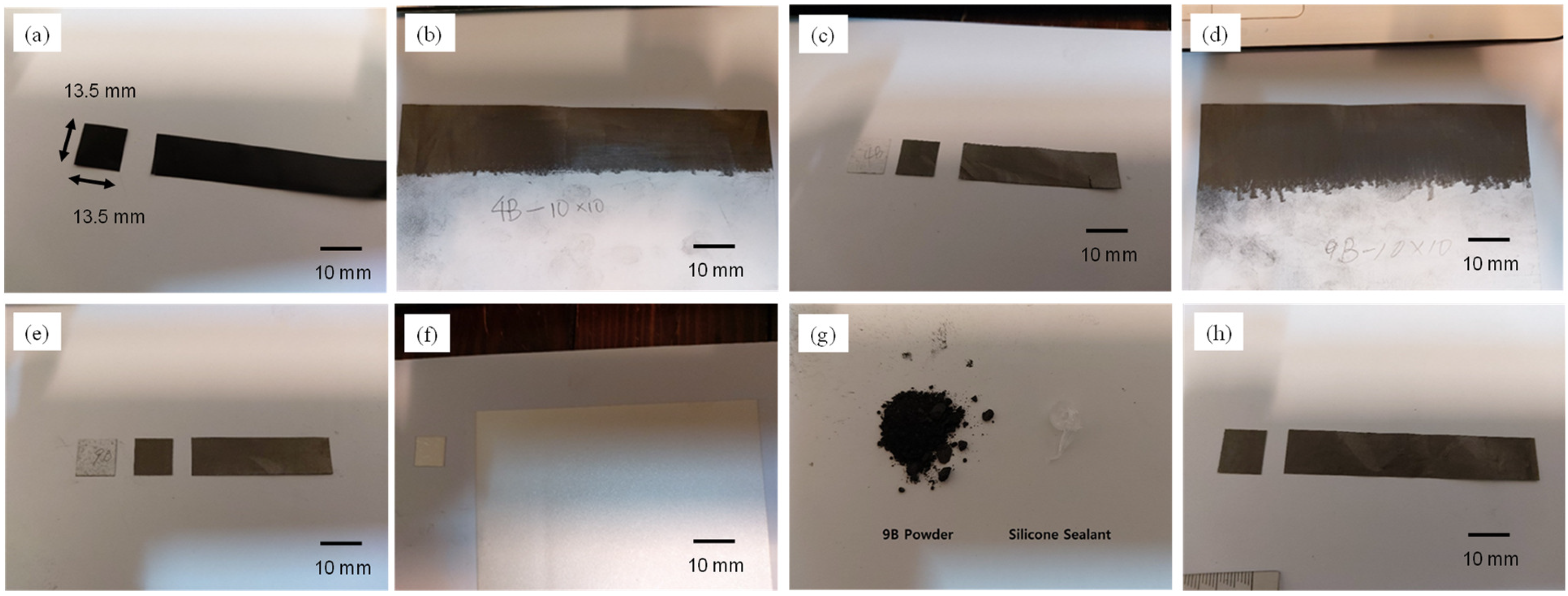
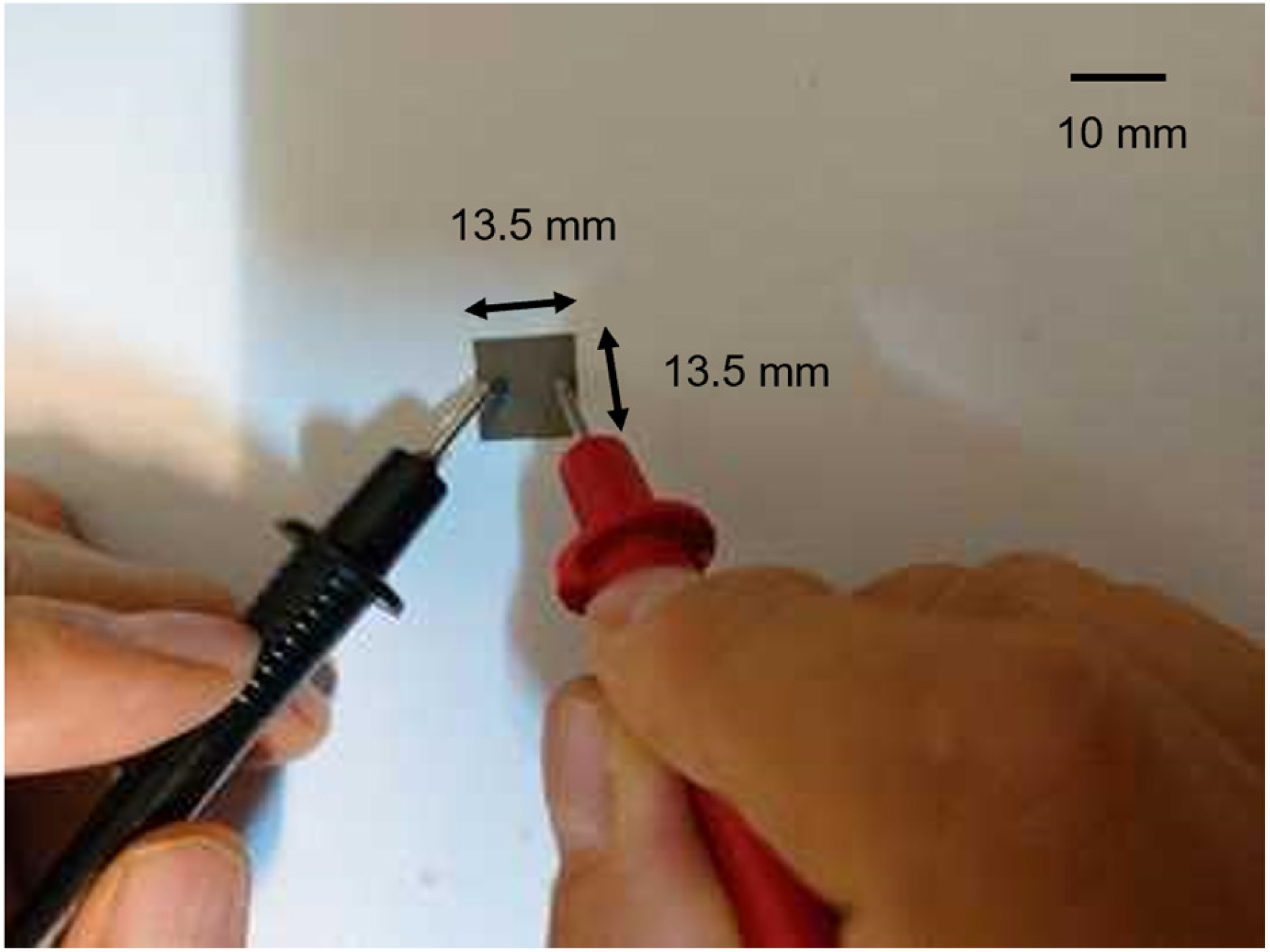
- Force-Sensitive Conductive Sheet (Velostat/Linqstat);Description: Velostat-1361 is a conductive polymer film made from polyolefin infused with carbon black, imparting electrical conductivity [33]. It is commonly used in packaging but has gained popularity among hobbyists for sensor applications due to its resistance-changing properties under bending or force.Application: Velostat is utilized in wearable devices such as shoes that light up when stepped on and systems analyzing the load on the foot’s grounding surface.Preparation: The 280 mm × 280 mm Velostat sheet was cut into 13.5 mm × 13.5 mm pieces to serve as the sensing part of the FSR sensor (Figure 1a).
- (2)
- Hand-made 4B Graphite Sheet;Description: Cretacolor Monolith woodless graphite pencil, 4B, was used to create a conductive sheet on A4 copy paper.Method: The paper was uniformly shaded horizontally and vertically, alternating directions for 10 strokes each. This sheet was then cut into 13.5 mm × 13.5 mm pieces (Figure 1b,c).
- (3)
- Hand-made 9B Graphite Sheet;Description: Similar to the 4B sheet but using a Cretacolor Monolith woodless graphite pencil, 9B.Method: The shading process was identical to the 4B sheet, with horizontal and vertical shading for 10 strokes each, then cutting into 13.5 mm × 13.5 mm pieces (Figure 1d,e).
- (4)
- Piezoelectricity Sheet;Description: Manufactured by Tyco Electronics (TE), this sheet uses silver ink to exhibit piezoelectric properties under mechanical load.Preparation: Specific details about the preparation are indicated in Figure 1f.
- (5)
- Mixture of 9B Pencil Lead Powder and Silicone Sealant;Description: A mixture of 9B pencil lead powder and silicone sealant was used to create a piezoresistive sheet.Method: The 9B pencil lead was shaved into a fine powder using a cutter knife. The powder was then mixed with silicone sealant in a 4:1 ratio to achieve a gel-like consistency. This mixture was evenly applied to copy paper using fingers to ensure uniform thickness and allowed to dry naturally for at least 12 h (Figure 1g,h).
2.2. Fabrication of the FSR Sensor
Step-by-Step Assembly
- (1)
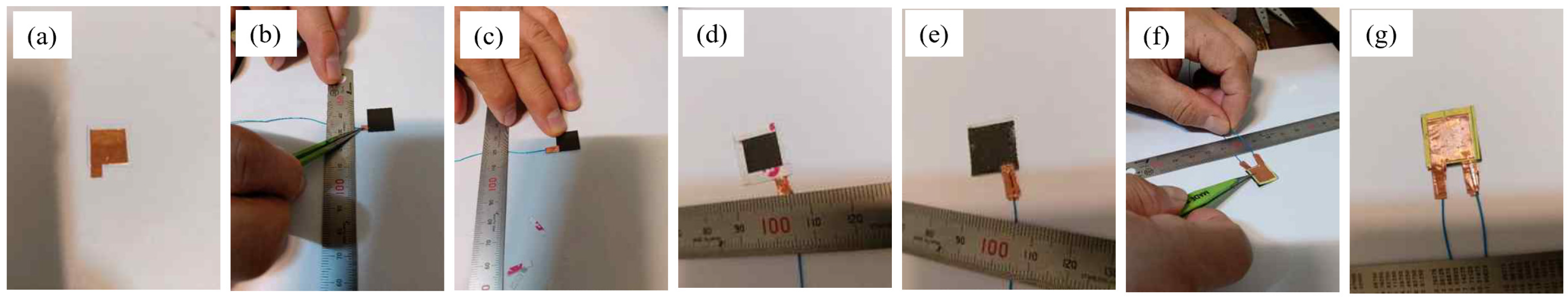
- Electrode attachment;Description: Copper foil (Cu foil) was attached to the back of each FSR sheet to serve as the electrode.Procedure: The Cu foil was adhered to the FSR sheet using conductive adhesive (Figure 3a).
- (2)
- Wire connection;Description: Wrapping wire (0.25 mm) was connected to the Cu foil and the FSR force surface to ensure electrical conductivity.Procedure: The wire was securely attached to the Cu foil (Figure 3b).
- (3)
- Covering and securing;Description: The Cu foil and wire assembly were covered and secured to the FSR sensor to ensure stability.Procedure: The covering process involved adhering the Cu foil and wire assembly as shown in Figure 3c.
- (4)
- Opposite side assembly;Description: The opposite side of the FSR sheet was assembled similarly, with the Cu foil and wire assembly.Procedure: The same steps were followed to prepare the opposite side of the sensor (Figure 3d).
- (5)
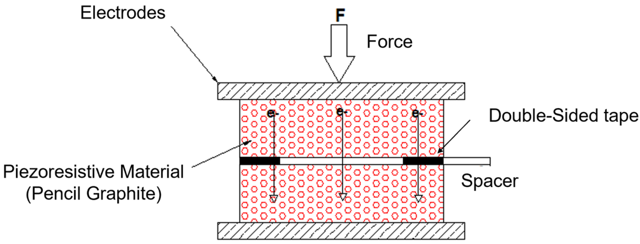
- Double-sided tape application;Description: Double-sided tape served as a spacer between the two FSR sheets.Procedure: The double-sided tape was adhered to one FSR sheet, and the protective paper was peeled off to expose the adhesive (Figure 3e).
- (6)
- Final Assembly;Description: The prepared opposite side was attached to the exposed adhesive side of the double-sided tape, completing the sensor assembly.Procedure: The final step involved carefully aligning and attaching the two FSR sheets (Figure 3f).
3. Results
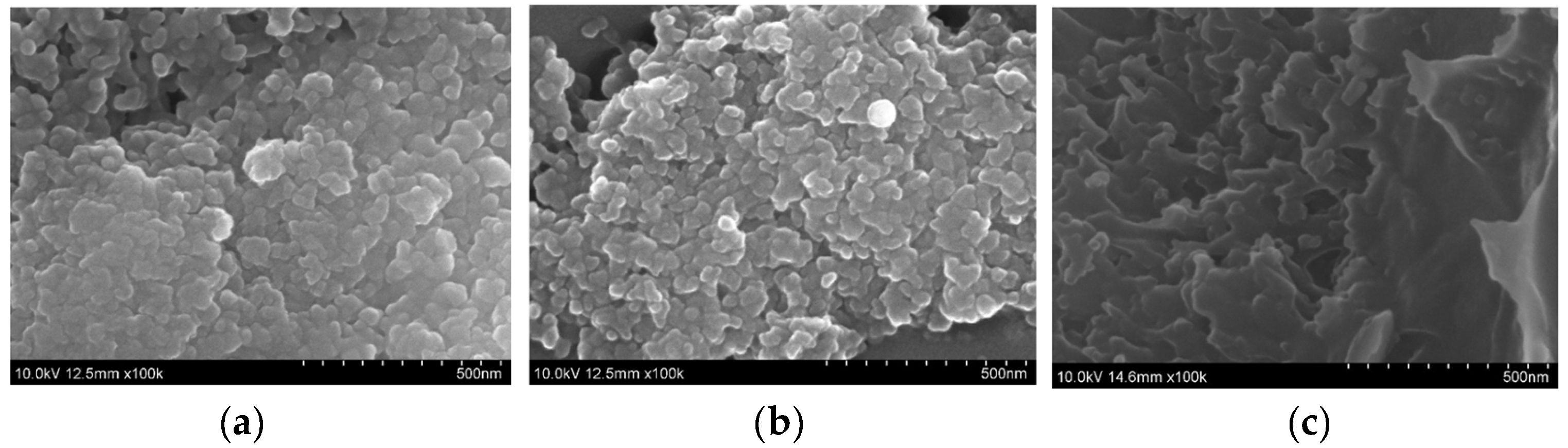
3.1. Analysis of Piezoresistive Components in FSR Sensors
3.2. Resistance of Fabricated FSR Sensors
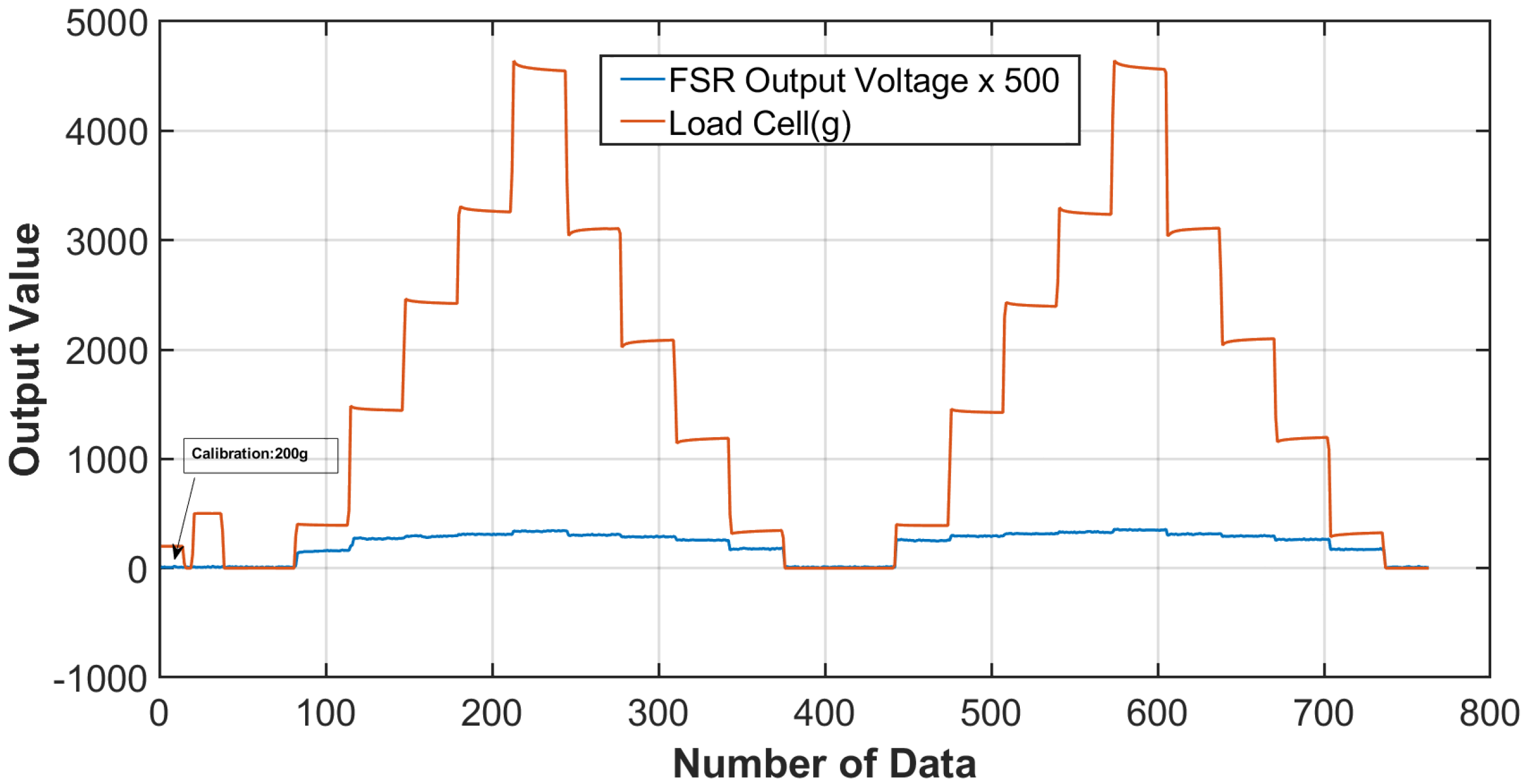
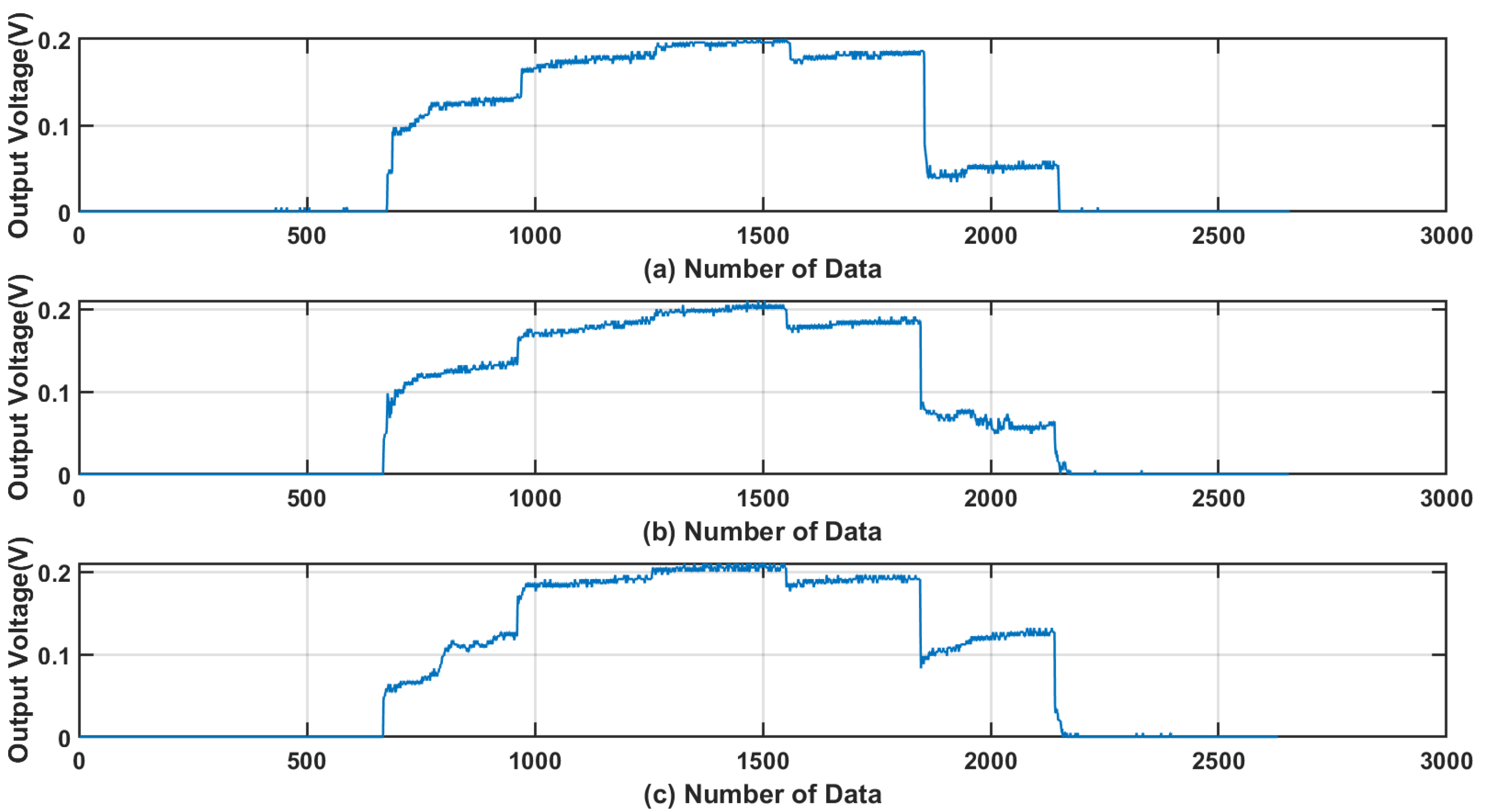
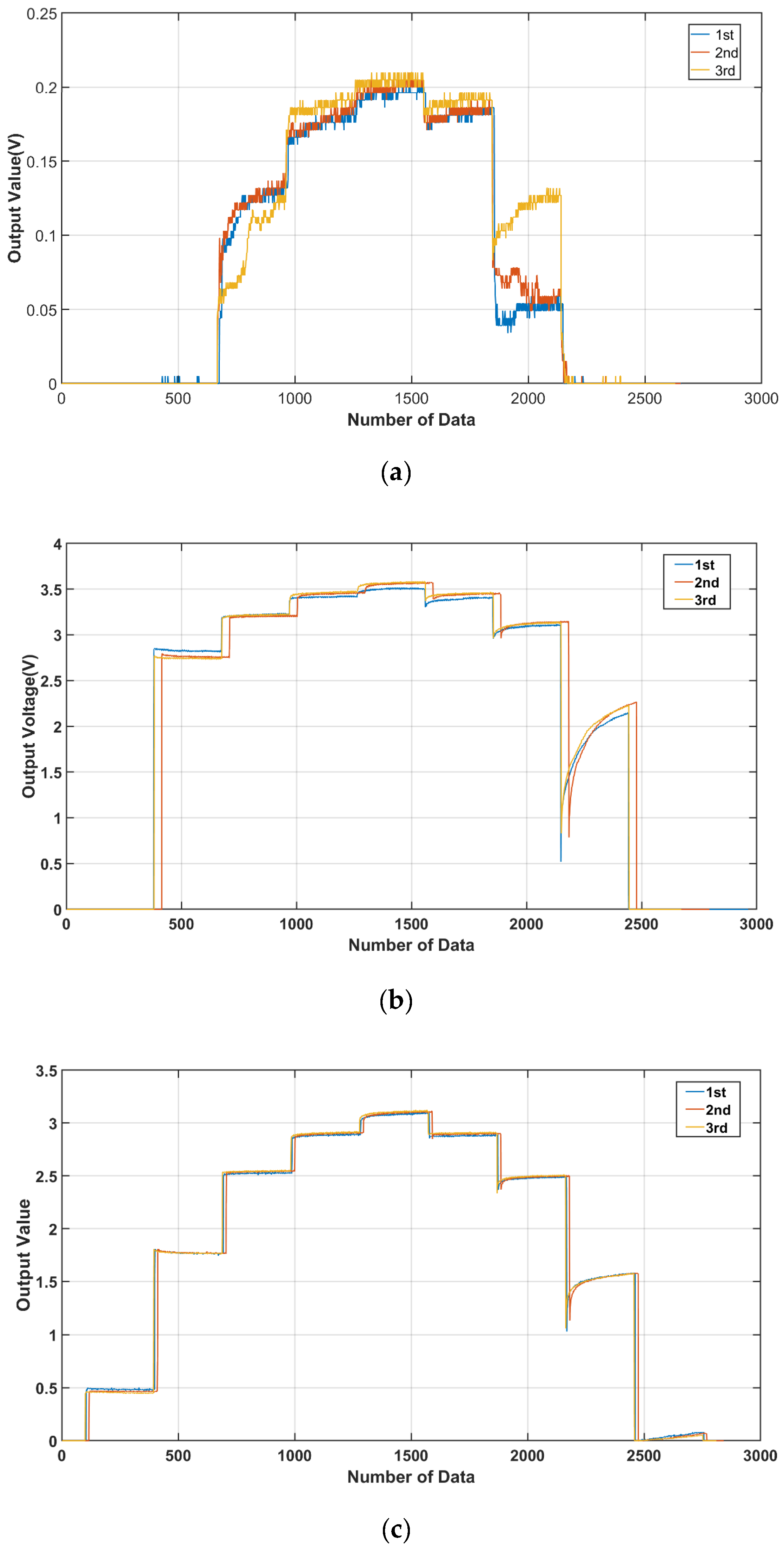
3.3. Load Test of the FSR Sensor
4. Discussion
5. Conclusions
Author Contributions
Funding
Institutional Review Board Statement
Informed Consent Statement
Data Availability Statement
Conflicts of Interest
References
- Chen, S.; Zhang, Y.; Li, Y.; Wang, P.; Hu, D. Recent Development of Flexible Force Sensors with Multiple Environmental Adaptations. Nano Energy 2024, 124, 109443. [Google Scholar] [CrossRef]
- Yeh, S.-K.; Hsieh, M.-L.; Fang, W. CMOS-Based Tactile Force Sensor: A Review. IEEE Sens. J. 2021, 21, 6276–6285. [Google Scholar] [CrossRef]
- Yang, W.; Qin, Y.; Wang, Z.; Yu, T.; Ge, Z. Recent Advances in the Development of Flexible Sensors: Mechanisms, Materials, Performance Optimization, and Applications. J. Electron. Mater. 2022, 51, 6735–6769. [Google Scholar] [CrossRef]
- Shen, G. Recent Advances of Flexible Sensors for Biomedical Applications. Prog. Nat. Sci. Mater. Int. 2021, 31, 872–882. [Google Scholar] [CrossRef]
- Jin, J.; Wang, S.; Zhang, Z.; Mei, D.; Wang, Y. Progress on Flexible Tactile Sensors in Robotic Applications on Objects Properties Recognition, Manipulation, and Human-Machine Interactions. Soft Sci. 2023, 3, 8. [Google Scholar]
- Cheng, M.; Zhu, G.; Zhang, F.; Tang, W.-L.; Jianping, S.; Yang, J.-Q.; Zhu, L.-Y. A Review of Flexible Force Sensors for Human Health Monitoring. J. Adv. Res. 2020, 26, 53–68. [Google Scholar] [CrossRef] [PubMed]
- Giovanelli, D.; Farella, E. Force Sensing Resistor and Evaluation of Technology for Wearable Body Pressure Sensing. J. Sens. 2016, 2016, 9391850. [Google Scholar] [CrossRef]
- Sadun, A.S.; Hassan, M.K.; Sam, M.F.; Jamaludin, M.Z.; Rashid, N.A.; Sharif, M.N.A. Force Sensing Resistor (FSR): A Brief Overview and the Low Cost Sensor for Active Compliance Control. Sens. Bio-Sens. Res. 2023, 35, 100433. [Google Scholar]
- Almassri, A.; Wada, C.; Wan Hasan, W.Z. Evaluation of a Commercial Force Sensor for Real-Time Applications. ICIC Express Lett. 2020, 11, 421–426. [Google Scholar]
- Hall, R.S.; Desmoulin, G.T.; Milner, T.E. A Technique for Conditioning and Calibrating Force-Sensing Resistors for Repeatable and Reliable Measurement of Compressive Force. J. Biomech. 2008, 41, 3492–3495. [Google Scholar] [CrossRef]
- Swanson, E.C.; Weathersby, E.J.; Cagle, J.C.; Sanders, J.E. Evaluation of Force Sensing Resistors for the Measurement of Interface Pressures in Lower Limb Prosthetics. J. Biomech. Eng. 2019, 141, 101009. [Google Scholar] [CrossRef]
- Srinivas, S.; Kumar, A.S. Surface-Activated Pencil Graphite Electrode for Dopamine Sensor Applications: A Critical Review. Biosensors 2023, 13, 353. [Google Scholar] [CrossRef]
- Kurra, N.; Kulkarni, G.U. Pencil-on-paper: Electronic Devices. Lab. Chip 2013, 13, 2866–2873. [Google Scholar] [CrossRef]
- Liao, X.; Liao, Q.; Yan, X.; Liang, Q.; Si, H.; Li, M.; Wu, H.; Cao, S.; Zhang, Y. Flexible and Highly Sensitive Strain Sensors Fabricated by Pencil Drawn for Wearable Monitor. Adv. Funct. Mater. 2015, 25, 2395–2401. [Google Scholar] [CrossRef]
- Ren, T.L.; Tian, H.; Xie, D.; Yang, Y. Flexible Graphite-on-Paper Piezoresistive Sensors. Sensors 2012, 12, 6685–6694. [Google Scholar] [CrossRef]
- Liu, H.; Crooks, R.M. Paper-Based Electrochemical Sensing Platform with Integral Battery and Electrochromic Read-Out. Anal. Chem. 2012, 84, 2528–2532. [Google Scholar] [CrossRef] [PubMed]
- Elangkovan, S.; Zainal Abidin, M.S.; Abd Rahman, S.F.; Che Soh, M.S.; Md Rashid, A.B. Economical Fabrication of Graphite/Paper-Based Humidity Sensor. Indones. J. Electr. Eng. Comput. Sci. 2020, 20, 54–59. [Google Scholar] [CrossRef]
- Zhang, Y.; Duan, Z.; Zou, H.; Ma, M. Drawn a Facile Sensor: A Fast Response Humidity Sensor Based on Pencil-Trace. Sens. Actuators B Chem. 2018, 261, 345–353. [Google Scholar] [CrossRef]
- Chen, X.; Mao, S.; Wang, Y.; Yu, H. Construction and Performance of a Flexible and Eco-Friendly Nanocellulose-Graphite-Based Pressure Sensor for Wearable Applications. In Proceedings of the 2023 IEEE International Conference on Flexible and Printable Sensors and Systems (FLEPS), Boston, MA, USA, 9–12 July 2023; pp. 1–4. [Google Scholar]
- Hussien, E.M.; Rizk, M.S.; Daoud, A.M.; El-Eryan, R.T. An Eco-friendly Pencil Graphite Sensor for Voltammetric Analysis of the Antidepressant Vilazodone Hydrochloride. Electroanalysis 2022, 34, 1402–1410. [Google Scholar] [CrossRef]
- Zhang, J.; Liu, Y.; Zhang, X.; Zeng, L.; Cui, T. Pencil-Trace on Printed Silver Interdigitated Electrodes for Paper-Based NO2 Gas Sensors. Appl. Phys. Lett. 2015, 106, 143101. [Google Scholar] [CrossRef]
- Xu, M.; Liang, T.; Shi, Z.; Chen, H.; Sun, Z. Pencil-Graphite-Paper Based On-Skin Electronics for Wearable Applications. Nat. Electron. 2020, 3, 130–136. [Google Scholar]
- Annu; Sharma, S.; Jain, R.; Raja, A.N. Review—Pencil Graphite Electrode: An Emerging Sensing Material. J. Electrochem. Soc. 2020, 167, 037501. [Google Scholar] [CrossRef]
- Ataide, V.N.; Arantes, I.V.S.; Mendes, L.F.; Rocha, D.S.; Baldo, T.A.; Coltro, W.K.T.; Paixão, T.R.L.C. Review—A Pencil Drawing Overview: From Graphite to Electrochemical Sensors/Biosensors Applications. J. Electrochem. Soc. 2022, 169, 047524. [Google Scholar] [CrossRef]
- Kawde, A.-N.; Baig, N.; Sajid, M. Graphite Pencil Electrodes as Electrochemical Sensors for Environmental Analysis: A Review of Features, Developments, and Applications. RSC Adv. 2016, 6, 91325. [Google Scholar] [CrossRef]
- Romanholo, P.V.V.; Sgobbi, L.F.; Carrilho, E. Chapter One—Exploring paper as a substrate for electrochemical micro-devices. Compr. Anal. Chem. 2020, 89, 1–29. [Google Scholar]
- Yang, T.H.; Shintake, J.; Kanno, R.; Kao, C.R.; Mizuno, J. Low-Cost Sensor-Rich Fluidic Elastomer Actuators Embedded with Paper Electronics. Adv. Intell. Syst. 2020, 2, 2000025. [Google Scholar] [CrossRef]
- Zhao, P.; Xie, P.; Song, Y.; Huang, S.; Zhou, K.; Ding, G.; Chen, X.; Han, S.-T.; Zhou, Y. High-Performance and Degradable All-Paper-Based Pressure Sensor from Conductive Polymer. Adv. Sens. Res. 2023, 2, 2200048. [Google Scholar] [CrossRef]
- Chowdhury, A.H.; Jafarizadeh, B.; Pala, N.; Wang, C. Paper-Based Supercapacitive Pressure Sensor for Wrist Arterial Pulse Waveform Monitoring. ACS Appl. Mater. Interfaces 2023, 15, 53043–53052. [Google Scholar] [CrossRef] [PubMed]
- Gao, L.; Zhu, C.; Li, L.; Zhang, C.; Liu, J.; Yu, H.-D.; Huang, W. All Paper-Based Flexible and Wearable Piezoresistive Pressure Sensor. ACS Appl. Mater. Interfaces 2019, 11, 25034–25042. [Google Scholar] [CrossRef]
- Li, W.; Xiong, L.; Pu, Y.; Quan, Y.; Li, S. High-Performance Paper-Based Capacitive Flexible Pressure Sensor and Its Application in Human-Related Measurement. Nanoscale Res. Lett. 2019, 14, 183. [Google Scholar] [CrossRef]
- Sakhuja, N.; Kumar, R.; Katare, P.; Bhat, N. Structure-Driven, Flexible, Multilayered, Paper-Based Pressure Sensor for Human–Machine Interfacing. ACS Sustain. Chem. Eng. 2022, 10, 9697–9706. [Google Scholar] [CrossRef]
- Andriu, D.; Ernestas, S.; Vytautas, B.; Urte, S.-B.; Baltramiejus, J.; Arunas, R.; Inga, M.-V. Polyethylene-Carbon Composite (Velostat®) Based Tactile Sensor. Polymers 2020, 12, 2905. [Google Scholar] [CrossRef] [PubMed]
- Hasnain, M.; Ullah, Z.; Sonil, N.I.; Ahmad, W.; Khalil, A.; Ali, S.M.; Mustafa, G.M.; Nazar, M.F.; Rouf, S.A.; Shamain, N.; et al. Ultrasensitive Strain Sensor Based on Graphite Coated Fibrous Frameworks for Security Applications. Mater. Today Commun. 2023, 37, 106859. [Google Scholar] [CrossRef]
- Lee, K.; Lee, J.; Kim, G.; Kim, Y.; Kang, S.; Cho, S.; Kim, S.; Kim, J.-K.; Lee, W.; Kim, D.-E.; et al. Rough-Surface-Enabled Capacitive Pressure Sensors with 3D Touch Capability. Small 2017, 13, 1700368. [Google Scholar] [CrossRef] [PubMed]


| FSR Sensor Material (Sheet) | Product Name | Comments |
|---|---|---|
| Velostat-1361 | Adafruit-1361 (New York, NY, USA) | Purchased |
| 4B Pencil + Paper (copy paper) | Cretacolor (Klagenfurt, Austria): Monolith 4B | Purchased |
| 9B Pencil + Paper (copy paper) | Monolith 9B | Purchased |
| TE Piezoelectricity Sheet | TE Conductivity (Schaffhausen, Switzerland) | Purchased |
| 9B + Silicone Sealant+Paper (copy paper) | Silicone Sealant for bathroom: Ohgong (Gwangju, Republic of Korea) | Purchased |
| Chemical Composition (%) | Flexiforce A201-1 | Flexiforce A201-25 | Interlink FSR-402 | |||
|---|---|---|---|---|---|---|
| 1st | 2nd | 1st | 2nd | 1st | 2nd | |
| C | 55.23 | 59.33 | 42.71 | 46.24 | 41.21 | 39.39 |
| O | 36.32 | 33.59 | 36.27 | 37.94 | 18.25 | 19.54 |
| Si | 8.45 | 7.01 | 20.02 | 15.81 | ||
| Sn | 40.53 | 41.08 | ||||
| FSR Sensor Name | Average Resistance | Comments | |
|---|---|---|---|
| 1 | Velsostat | 25.2 kΩ | Hand-made sensor |
| 2 | 4B | 37.12 kΩ | Hand-made sensor |
| 3 | 9B | 13.7 kΩ | Hand-made sensor |
| 4 | TE | 0.27 Ω | Hand-made sensor |
| 5 | 9B + silicone sealant | 0.88 MΩ | Hand-made sensor |
| 6 | Interlink FSR-402 | 0.2 MΩ | Commercial sensor |
| 7 | Flexiforce A201-1 | 1.71 MΩ | Commercial sensor |
| 8 | Flexiforce A201-25 | 33.52 MΩ | Commercial sensor |
| 9 | Flexiforce A201-100 | 53.1 MΩ | Commercial sensor |
Disclaimer/Publisher’s Note: The statements, opinions and data contained in all publications are solely those of the individual author(s) and contributor(s) and not of MDPI and/or the editor(s). MDPI and/or the editor(s) disclaim responsibility for any injury to people or property resulting from any ideas, methods, instructions or products referred to in the content. |
© 2024 by the authors. Licensee MDPI, Basel, Switzerland. This article is an open access article distributed under the terms and conditions of the Creative Commons Attribution (CC BY) license (https://creativecommons.org/licenses/by/4.0/).
Share and Cite
Jung, J.; Lee, K.; Kim, B. Rapid and Cost-Effective Fabrication and Performance Evaluation of Force-Sensing Resistor Sensors. Appl. Sci. 2024, 14, 7774. https://doi.org/10.3390/app14177774
Jung J, Lee K, Kim B. Rapid and Cost-Effective Fabrication and Performance Evaluation of Force-Sensing Resistor Sensors. Applied Sciences. 2024; 14(17):7774. https://doi.org/10.3390/app14177774
Chicago/Turabian StyleJung, Jinwoo, Kihak Lee, and Bonghwan Kim. 2024. "Rapid and Cost-Effective Fabrication and Performance Evaluation of Force-Sensing Resistor Sensors" Applied Sciences 14, no. 17: 7774. https://doi.org/10.3390/app14177774
APA StyleJung, J., Lee, K., & Kim, B. (2024). Rapid and Cost-Effective Fabrication and Performance Evaluation of Force-Sensing Resistor Sensors. Applied Sciences, 14(17), 7774. https://doi.org/10.3390/app14177774