Article

Research on Ride Comfort Control of Air Suspension Based on Genetic Algorithm Optimized Fuzzy PID

1
School of Mechanical Engineering, Tianjin University, Tianjin 300350, China
2
School of Mechanical and Electrical Engineering, Hainan University, Haikou 570228, China
*
Author to whom correspondence should be addressed.
Appl. Sci. 2024, 14(17), 7787; https://doi.org/10.3390/app14177787
Submission received: 3 June 2024 / Revised: 3 July 2024 / Accepted: 8 July 2024 / Published: 3 September 2024

Abstract

:
The air suspension system’s superior variable stiffness, low vibration frequency, and resistance to road impacts significantly elevate both the comfort of vehicle occupants and the overall ride quality. By effectively controlling the air suspension system, its superior characteristics can be fully exploited to enhance the overall performance of vehicles. However, the parameter tuning process of the fuzzy PID controller for air suspension involves subjectivity and blindness, which affects the performance of the suspension system. To overcome these shortcomings, a control strategy combining genetic algorithms with fuzzy PID control is proposed. This strategy involves a genetic algorithm-optimized fuzzy PID air suspension control approach specifically targeting the fuzzy PID controller for air suspension. A 1/4 two-degree-of-freedom air suspension fuzzy PID controller is designed in MATLAB 2019a, utilizing genetic algorithms to optimize the PID parameter tuning process. The ride comfort of the fuzzy PID air suspension after tuning is then investigated. In the study of ride comfort on Class B road surfaces, the simulation and experimental results were consistent. Using a genetic algorithm to optimize a fuzzy PID-controlled air suspension resulted in reductions of the root mean square values for vertical body acceleration, suspension deflection, and wheel dynamic load by 30%, 26%, and 9%, respectively, compared to passive suspension. These reductions are further improvements over the corresponding indices controlled by the fuzzy PID alone, which decreased by 23%, 18%, and 6%, respectively. Thus, the control effect of the genetic algorithm-optimized fuzzy PID is superior to that of the fuzzy PID control. This demonstrates that the fuzzy PID control of air suspension optimized by genetic algorithms can further improve the comfort of vehicle occupants and the ride comfort of driving, providing a reference for active control of air suspension systems.

1. Introduction

The air suspension system boasts superior attributes such as variable stiffness, low vibration frequency, and resistance to road impacts. When integrated into vehicle suspension systems, it significantly improves both ride comfort and handling stability while also minimizing damage to road surfaces [1]. Particularly, the electronic control air suspension system can adjust control forces based on input parameters, enabling adjustments to vehicle posture (especially vehicle height). According to various driving conditions, the suspension system achieves optimal matching and coordinated control of stiffness and damping to adapt to various vehicle usage scenarios, thereby improving the overall performance of vehicles. Li Yanchao conducted control research on the suspension system of electric vehicles by establishing PID control semi-active suspension models and skyhook damping control semi-active suspension models. The results indicated that the PID control semi-active suspension increased the peak value and root mean square (RMS) of suspension dynamic deflection, while the skyhook damping control semi-active suspension increased the peak value and RMS of tire dynamic deformation. This verified the mutual influence among suspension smoothness evaluation indicators, demonstrating that improving one performance aspect might reduce another [2]. Sun Shilei studied vehicle ride comfort by investigating the height adjustment of air springs during the inflation and deflation process of electronically controlled active air suspension. By applying fuzzy PID controllers and BP-PID controllers to analyze the vehicle ride comfort during height changes of free diaphragm air springs, it was found that the fuzzy PID controller effectively suppressed the vertical acceleration of the car body, particularly when the vertical acceleration exceeded 1.0 m/s2. The BP-PID controller effectively suppressed vertical acceleration above 0.8 m/s2, thereby improving ride comfort [3]. Bai Rui presented an adaptive sliding-mode control method, which is used to stabilize the displacement of electronically controlled air suspension in the presence of parameter uncertainties. Simulation research showed that the proposed control method can obtain satisfactory control performance for electronically controlled air suspension [4]. A hybrid fuzzy and proportional-integral-derivative (PID) controller is proposed for roll angle handling of a three-axle truck with an active air suspension system, the pitch angle is controlled by the active suspension system. Roll reduction of a heavy vehicle can improve the ride comfort and rollover tendency of the truck [5]. A fuzzy controller is proposed for the insufficient roll resistance of D23. The results show that the designed controller can further effectively improve the handling stability of vehicles [6]. An optimal fuzzy control with control rules optimized by the genetic algorithm is proposed to evaluate the performance of the control damping and the control air spring of the vehicle air suspension system on ride comfort and road friendliness [7]. An innovative design of an adaptive air suspension system with an LQR control strategy is proposed, and a dynamic model of an air suspension system used in passenger vehicles was designed and simulated for both passive and adaptive systems in MATLAB [8]. A height control strategy for the sprayer body was formulated, and sliding mode control and the on-off control were used to design the suspension height stability controller. The simulation experiment results showed that sliding mode control and on–off control could track and stabilize the height of the sprayer body when it changed under no excitation and D-grade road random excitation. Compared with the on–off control method, the sliding mode control approach had good control ability and precision due to its robustness to change in model parameters [9].
Domestic and international scholars conducted control research on suspension systems based on PID control theory [10,11,12,13,14]. The air suspension system simulation model with PID controller was built, and the experimental results show that air suspension based on PID control strategy can reduce the body vertical acceleration and better increase the ride comfort of vehicles [10]. PID controller and LQR controller for an active suspension system are analyzed, evaluated, and compared. The results have shown that the PID controller supports the optimization of the body acceleration, and the LQR controller supports the optimization of the body displacement [11]. An advanced firefly algorithm was investigated to compute the PID controller for a semi-active suspension system. The study of the controllers has shown significant improvement as the proposed PID-AFA is capable of reducing the amplitude of the sprung acceleration and body acceleration responses up to 56.5% and 67.1% [12]. The PID controller is researched and applied to control the active suspension system of the cars under the different excitations of the road surface and the various car speeds. The research results show that the PID controller for the car suspension system has an obvious impact on reducing the vibration and controlling the car body shaking in comparison with the passive suspension system [13]. Using the Ziegler–Nichols method via the Control System Designer app to tune the PID controller to achieve the desired comfort traveling of passengers and reliable ride-holding of the car [14]. However, they did not provide a clear and effective method for selecting specific control parameters, and the use of PID structures introduced various uncertainties and nonlinearities, making it difficult to determine appropriate PID gains to enhance the robustness of the control system. Therefore, intelligent algorithms like fuzzy logic were employed to fine-tune PID controller gains, enhancing the robustness of the control system. Fuzzy PID control merges the features of PID control with fuzzy control characteristics, offering rapid convergence, robust performance, and a streamlined structure [15,16,17,18]. However, due to the complexity of air suspension systems, the subjective selection of membership functions, fuzzy rules, and PID initial parameters based on experience hindered achieving optimal control effectiveness. Literature [19,20,21] proposed using genetic algorithms to optimize the initial PID parameters of fuzzy PID controllers. However, the fuzzy rules defined in the study still relied on expert experience, making it challenging to achieve optimal control. To address these issues, genetic algorithms were combined with fuzzy PID control to propose a genetic algorithm-optimized fuzzy PID control strategy. A genetic algorithm-optimized fuzzy PID control system tailored for air suspension systems was designed to conduct control research on air suspension systems.

2. Dynamic Modeling of Air Suspension Systems

2.1. Vehicle Model Construction

The air suspension system is a rather complex nonlinear system, making it difficult to establish an accurate model. In a study of vehicle performance, the suspension system should be simplified based on the specific research problem. Key aspects that require detailed investigation should be thoroughly analyzed, while factors with a minimal impact on certain performance characteristics should be simplified or omitted. This approach ensures that the simplified system model retains the main features pertinent to the research problem while remaining both straightforward and practical.
Within the scope of vehicle ride comfort research, focusing primarily on the vertical dynamics of the vehicle, the following assumptions are made based on the operational characteristics of the suspension system.
(1)
During vehicle operation, the road surface unevenness excitation experienced by the left and right tires is identical;
(2)
The effects of the engine, steering, and drivetrain systems on vibrations are neglected in the modeling process;
(3)
The damping of the tires is significantly less than that of the suspension dampers; hence, only the stiffness of the tires is considered, and tire damping is ignored in the modeling;
(4)
The time delay effect of the suspension is neglected in the modeling.
Based on these assumptions, when the vehicle is symmetrical about its longitudinal axis and the left and right wheels experience identical road surface unevenness, the vehicle exhibits only vertical and pitch vibrations. These two degrees of freedom have the most significant impact on ride comfort. In this scenario, the vehicle can be approximated as a planar model. When the mass distribution coefficient of the vehicle’s sprung mass approaches 1, the vertical motion of the concentrated masses above the front and rear axles can be considered independent of each other [22]. Thus, the study of vertical dynamics can be simplified to the vertical motion of a single-axle body. For the analysis of ride comfort, the vehicle model considers one degree of freedom in the vertical direction for the sprung mass and one vertical degree of freedom for the wheel mass, totaling two degrees of freedom. Therefore, the vehicle model is simplified to a quarter-vehicle model. Despite representing only a quarter of the entire vehicle, the quarter-vehicle model retains all the characteristics relevant to suspension studies in practical research contexts.
The 1/4 vehicle model can accurately describe the basic motion state of the vehicle. Moreover, when applying control, it exhibits higher credibility in control effectiveness, and the control effort required for controller design can be simplified. Figure 1 depicts the two-degree-of-freedom 1/4 vehicle model, wherein linear springs replace elastic tires, and tire damping is neglected.
Based on Newtonian mechanics laws, combined with the air spring model, a 1/4 vehicle dynamic model was established.
m 1 z ¨ 1 c z ˙ 2 z ˙ 1 + k t z 1 q + F m 2 g + U = 0 m 2 z ¨ 2 + c z ˙ 2 z ˙ 1 F m 2 g U = 0
In Equation (1), “m1” represents the unsprung mass, “m2” represents the sprung mass, “kt” is the tire stiffness coefficient, “c” is the suspension damping coefficient, “F” denotes the air spring force, “U” represents the active control force, “Z1”, “Z2”, and “q” respectively denote the displacement of the unsprung mass, the displacement of the sprung mass, and the road input excitation.

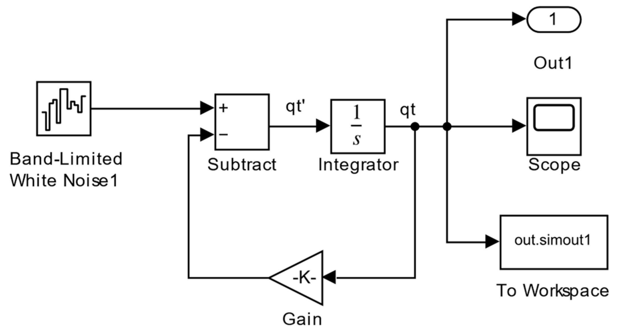
2.2. Road Input Model

During actual driving, vehicles are subject to various external influences, such as lateral winds and road surface unevenness. The study of vehicle ride comfort primarily focuses on the vibrations induced by road surface unevenness. Therefore, the current analysis only considers the effects brought about by road surface irregularities. Road inputs can generally be categorized into two types: deterministic and stochastic inputs. Deterministic road inputs are used when simulating road irregularities like bumps and potholes, which pose significant challenges to vehicle navigation. On the other hand, stochastic road inputs describe the continuous excitation of the road through their statistical properties, providing a standard classification of road quality that better reflects real-world driving conditions. In this study, stochastic road inputs are analyzed, and their mathematical model is established.
Random road profiles were used as input to study the characteristics of the suspension system. The displacement power spectral density and variance described the random road model, with its displacement power spectral density as follows:
G q n = G q n 0 n n 0 W
where, “n0”—the reference spatial frequency, n0 = 0.1 m−1;
n”—the spatial frequency, which is the reciprocal of the wavelength λ, indicating the number of wavelengths contained per unit length, m−1;
Gq(n0)”—the road roughness coefficient, m3;
W”—the frequency coefficient, determining the frequency structure of the power spectral density, commonly taken as W = 2.
Using MATLAB/Simulink (Natick, MA, USA), a road surface white noise model was constructed with a Class B road surface at a vehicle speed of 50 km/h. According to GB7031-1987 [23], the road roughness coefficient Gq(n0) is 6.4 × 10⁻⁵ m3. Figure 2 depicts the simulated road surface model, while Figure 3 shows the time-domain variation of road excitation at 50 km/h. Using MATLAB/Simulink, a road surface white noise model was constructed, selecting a Class B road surface and a vehicle speed of 50 km/h. According to GB7031-1987, the road roughness coefficient Gq(n0) = 6.4 × 10⁻⁵ m3. Figure 2 illustrates the simulated road surface model, and Figure 3 depicts the time-domain variation of road excitation at 50 km/h.

2.3. Selection of Simulation Parameters

In studying suspension performance, three parameters are typically used to evaluate ride comfort: tire dynamic load, vehicle body acceleration, and suspension dynamic deflection. A smaller vehicle body acceleration indicates a more stable suspension, while a smaller suspension dynamic deflection also signifies greater stability. Tire dynamic load should remain within a certain range; excessive load can accelerate tire wear and hinder road maintenance, while insufficient load affects tire traction, impacting vehicle stability.
The study focuses on the air suspension of a specific model of sedan, with model parameters listed in Table 1.

3. Control Algorithm

3.1. PID Controller

PID control is a widely applied control strategy in industrial process control. PID stands for Proportional, Integral, and Derivative and involves adjusting these three parameters to achieve precise control over a system. The basic principle of PID control is to calculate an output based on the deviation between a desired setpoint and the current value of the system. This calculation is performed according to proportional, integral, and derivative relationships. The resulting output is used to control the system, enabling it to reach and stabilize at the desired setpoint.
In the PID control strategy, system control is achieved through three processes: proportional, integral, and derivative, combined with the relative control error output from the system. When designing the system, appropriate weighting coefficients “Kd”, “Ki”, and “Kp” for derivative, integral, and proportional terms are chosen based on the performance requirements of the air suspension. During the tuning process of control parameters, the performance changes in the time domain of the control system are considered, as shown in Table 2 (using the example of a relative increase in tuning parameters).
Using the PID control method, the difference between the ideal vertical acceleration of the car body (acceleration is 0) and the actual vibration acceleration was directly input into the controller. The active control force of the air suspension system served as the output. Through a “trial and error” method, the values of the three parameters “Kp”, “Ki”, and “Kd” were continuously adjusted. The corresponding output curves were observed, and parameter values were tuned based on the control effect. Finally, the three parameters of the PID controller were determined as follows: Kp = 1, Ki = 53, Kd = 0.1.
Based on the above principle, the road input system, air suspension simulation module, and PID control system were combined in Simulink to establish a PID control air suspension simulation model for simulation analysis. The suspension control simulation model is shown in Figure 4, and the vehicle parameters are listed in Table 2.

3.2. Fuzzy PID Controller

F-PID, or Fuzzy PID, utilizes fuzzy logic algorithms and PID control methods to dynamically optimize PID parameters based on specific fuzzy rules. This approach addresses the limitations of traditional PID controllers that cannot adjust parameters effectively. In air suspension control, integrating fuzzy reasoning with PID control allows for the adjustment of parameters according to system requirements, ultimately achieving effective system control.
Utilizing fuzzy logic and the PID control method, the input variables of fuzzy inference were set as the deviation “e” and the rate of change of deviation “ec” of the vehicle’s vertical acceleration. The fuzzy algorithm rules were employed to tune the control parameters of PID, constructing a two-dimensional fuzzy PID controller [15]. This strategy combined the stability performance of PID control with the good dynamic tracking capability of fuzzy control [17]. The operational principle is depicted in Figure 5.

3.2.1. Input and Output of Fuzzy Controller

The vertical acceleration “e” and the rate of change of vertical acceleration “ec” serve as input signals to this controller. Through processes such as fuzzy inference and parameter adjustment, the controller obtains the final output values, namely “ΔKp”, “ΔKi”, and “ΔKd”. These values primarily influence the adjustment of the switching time of the electromagnetic valves and the regulation of airbag pressure, thereby adjusting the stiffness of the air suspension. The final PID parameter values can be obtained accordingly.
K P = K p + K p K i = K i + K i K d = K d + K d
In the Equation, the initial settings of the fuzzy PID are sequentially designated as “Kp′”, “Ki′”, and “Kd′”; The correction amounts “ΔKp”, “ΔKi”, and “ΔKd” are real-time self-adjustments of PID parameters for the suspension system based on actual driving conditions, determined through fuzzy inference; The PID parameter real-time self-adjustment of the suspension system based on actual driving conditions is derived through fuzzy inference. The final parameter settings of the fuzzy PID are denoted as “Kp”, “Ki”, and “Kd”.
Based on the passive suspension test results, the fuzzy domains of the controller input variables “e”, “ec”, and output variables “ΔKp”, “ΔKi”, and “ΔKd” were all selected as [−6, 6]. The quantization factor was Ke = 7.8, Kec = 1.2, and the proportional factor was Ku = 8. The initial values of the fuzzy PID controller parameters were Kp′ = 1, Ki′ = 53, and Kd′ = 0.1.

3.2.2. Selection of Input and Output Variable Domains

Before applying fuzzy control, the input variables undergo fuzzification. Typically, the system’s input parameters are crisp values that are mapped to corresponding fuzzy subsets and membership functions. This process is known as fuzzification. The subsequent operations of the fuzzy controller require the fuzzification of the inputs e and ec. The range of values for e and ec is commonly referred to as the fundamental domain.
Suppose the fundamental domains for the input error and error rate of change are [−e, e] and [−ec, ec], respectively, and the fundamental domain for the output is [−u, u]. If the fuzzy domain for the input is set as [−n, −n + 1,…, 0,…, x − 1, x], then the domain for the error rate of change can be determined as [−m, −m + 1,…, 0,…, m − 1, m], and the output fuzzy domain is [−x, −x + 1,…, 0,…, x − 1, x]. Typically, the input domain is set such that n ≥ 6 and the output domain such that m ≥ 6. For this case, n = m = 6 is selected.
In general, after discretization, e and ec typically need to be transformed to correspond with fuzzy domains using a quantization factor. The expression for the quantization factor is as follows:
K e = n e , K e c = m e c , K u = x u  
Based on passive suspension experiments, the fundamental domains for e and ec are [−0.7, 0.7] and [−5, 5], respectively. The fundamental domains for Kp, Ki, and Kd are [−6, 6], [−1, 1], and [−100, 100], respectively. The fuzzy domains for input and output are both set to {−6, 6}. The constants are Ke = 7.8, Kec = 1.2, Up = 1, Ui = 0.167, and Ud = 16.67. The initial values are Kp′ = 1, Ki′ = 53, and Kd′ = 0.1.

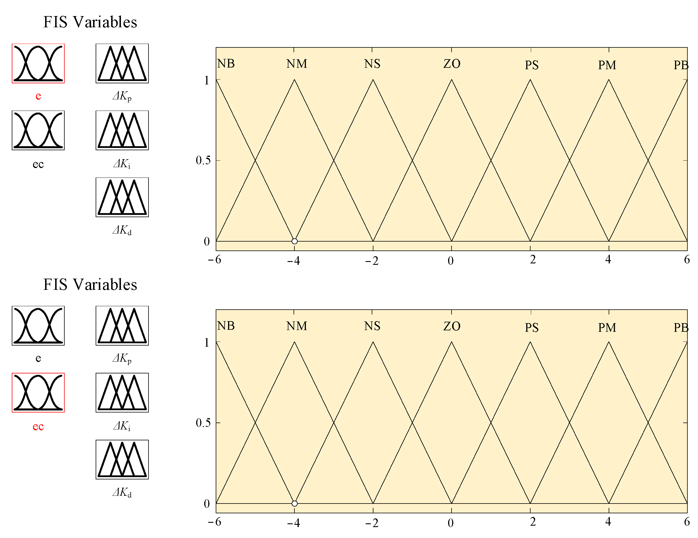
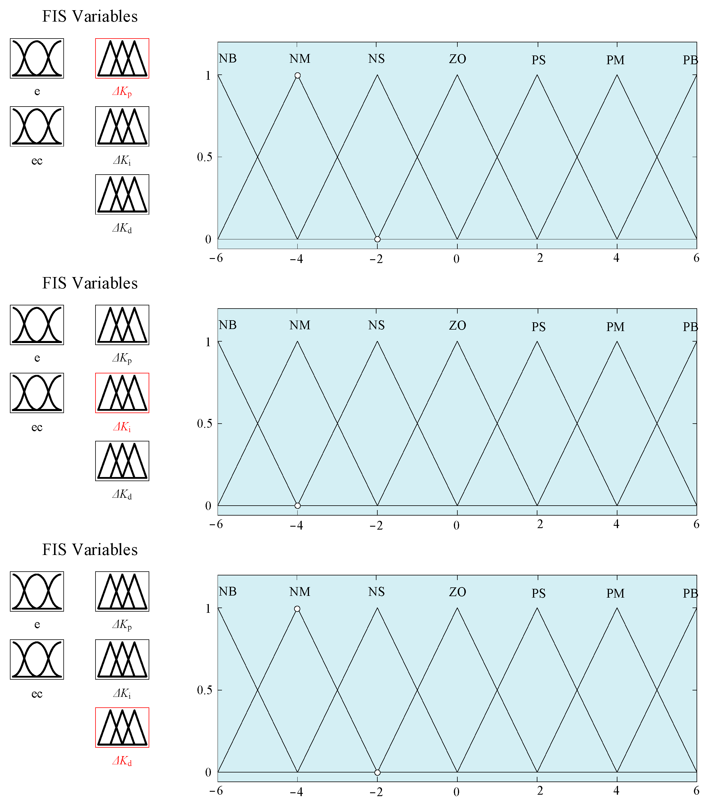
3.2.3. Membership Functions of Fuzzy Variables

The membership functions within the input and output ranges are triangular membership functions. This function can rapidly respond to the occurrence of an error and generate a corresponding adjustment output. Additionally, its computation and expression are relatively simple, and it requires minimal memory space. [NB, NM, NS, ZO, PS, PM, PB] represent the fuzzy subsets of the input and output fuzzy variables. The fuzzy controller employs the Mamdani model and adheres to the following principles when designing control rules: for large errors, the control actions are chosen to prioritize rapid error elimination; for small errors, the control actions prioritize stability to prevent system overshoot. Additionally, the centroid method is utilized for fuzzy decision-making. The centroid method is an ideal defuzzification technique whose fundamental principle involves computing the centroid of the area under the membership function curves. This approach provides smoother output in inferential control. The membership function curves for the input and output are illustrated in Figure 6 and Figure 7.

3.2.4. Establishment of Fuzzy Control Rules

In the process of designing a control system, establishing fuzzy PID control rules is particularly crucial. Fuzzy control rules are formulated based on the linguistic values of input and output variables, arranged or combined to form fuzzy conditional statements. According to the variation patterns in the excitation response of the suspension system, the following control rules are established:
(1)
When |e| undergoes significant changes, choose a larger ∆Kp and smaller ∆Ki, ∆Kd to ensure system stability and effectively control the instantaneous deviation;
(2)
If there are no significant changes in |e| and |ec|, reduce ∆Kp appropriately and select suitable ∆Ki, ∆Kd based on system requirements to ensure minimal overshoot and effectively reduce system response time;
(3)
When |e| changes minimally, increase the values of ∆Kp and ∆Ki, adjusting ∆Kd based on the variation in |ec|. For small |ec|, choose a larger ∆Kd; for large |ec|, choose a smaller ∆Kd;
(4)
When e and ec change in the same direction, indicating an increasing error trend, increase ∆Kp; conversely, decrease ∆Kp.
Based on the variation pattern of the suspension system excitation response and in combination with the actual response during the operation of the air suspension system, the fuzzy control rules corresponding to Table 3, Table 4 and Table 5 were organized and summarized based on operational experience and expert knowledge.

3.3. GA F-PID Controller

A genetic algorithm is a probabilistic optimization algorithm that conducts a probabilistic search based on the natural genetic mechanisms and biological evolution principles in nature, iteratively seeking the optimal solution. It relies on the principles of biological evolution and natural selection, using individual fitness as a basis to perform selection, crossover, and mutation operations to intelligently search for optimal parameter solutions. This intelligent algorithm can optimize one or multiple parameters of a system, thereby enhancing the effectiveness of the controller.
A genetic algorithm is employed to optimize the control rules and membership functions in F-PID controllers, aiming to achieve superior control performance.

3.3.1. Selection of Objective Function

Based on the passive suspension tests and expert experience, when selecting the optimization range for the initial parameters of the fuzzy PID controller, the range of “Kp” was set to [0, 10], the range of “Ki” was set to [0, 10], and the range of “Kd” was set to [0, 5].
When designing a suspension system to enhance vehicle performance, it is necessary to improve the ride comfort, which can be judged based on the vehicle body’s vibration acceleration. The overall posture of the vehicle body is determined by the suspension’s dynamic travel, and this parameter value varies depending on the different suspension structures. The ground-contact performance of the wheels during driving can be described by the tire dynamic load. These three parameters describe the suspension’s performance from different aspects, making them suitable as evaluation indicators. Therefore, the overall performance of the suspension can be judged based on the values of these three parameters. Assuming both active and passive suspensions operate under the same conditions, the objective function for genetic algorithm optimization is constructed by dividing the performance indicators of active suspension by those of passive suspension under identical conditions.
min Q x = J 1 J A + J 2 J S + J 3 J D
s . t . J 1 J A J 2 J S J 3 J D
In the Equation, “Q(x)” represents the objective function; “J1”, “J2”, and “J3” respectively denote the root mean square values of the vehicle vertical acceleration, suspension wheel travel, and dynamic tire load for the active air suspension; “JA”, “JS”, and “JD” respectively represent the root mean square values of the vehicle vertical acceleration, suspension wheel travel, and dynamic tire load for the passive air suspension under the same operating conditions.

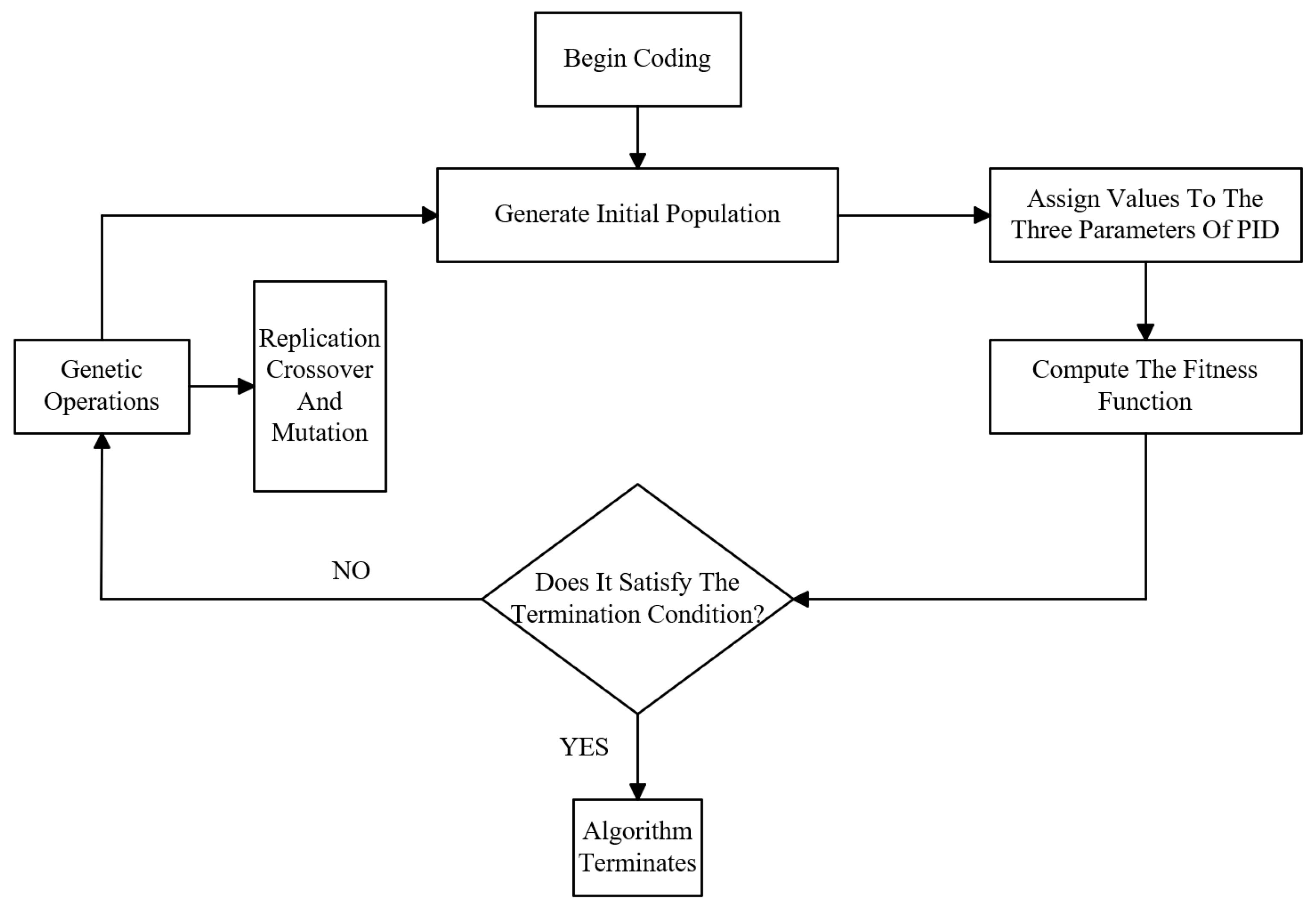
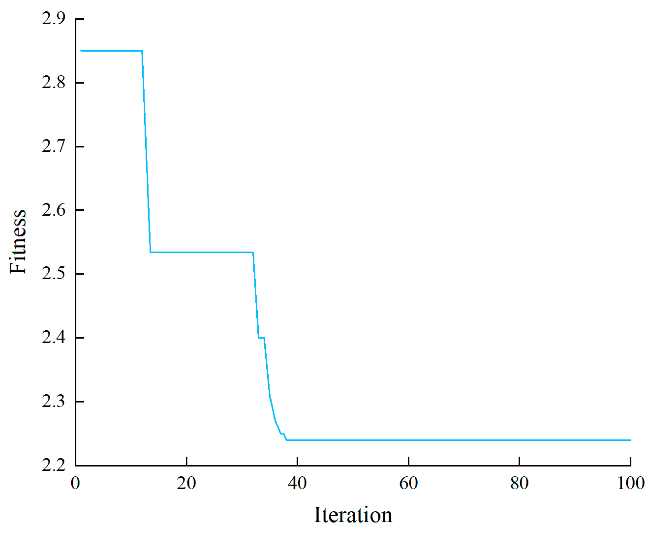
3.3.2. Controller GA Optimization Algorithm

The genetic algorithm achieves optimization through operations such as selection, crossover, and mutation, seeking the optimal solution with the maximum fitness value in the population. The parameter tuning process is shown in Figure 8, and the parameter settings are detailed in Table 6.
The fitness function for this genetic algorithm optimization was set as the reciprocal of the objective function, as shown in Equation (7). The representation of control effectiveness (suspension performance) improves with increasing fitness value.
f = 1 Q x = 1 J 1 J A + J 2   J S + J 3 J D
When using genetic algorithms for controller parameter optimization, the fuzzy PID controller model was invoked, and the suspension ride comfort index was input into the optimization main program of the GA. Genetic algorithms utilize fitness functions to control the program’s operation and determine termination conditions based on the maximum number of iterations. When the genetic algorithm program reaches a specific number of iterations, it will automatically terminate and output the optimal solution. After 100 iterations, the curve of fitness function variation was obtained, as shown in Figure 9.
From Figure 9 it can be observed that starting from generation 38, the fitness value tends to stabilize at 2.2441. At this point, the optimal variables are determined to be (Kp, Ki, Kd) = (10, 6, 1.5). A simulation analysis of the air suspension system was conducted in Simulink using the vehicle model parameters as listed in Table 1.

4. Experimental Research

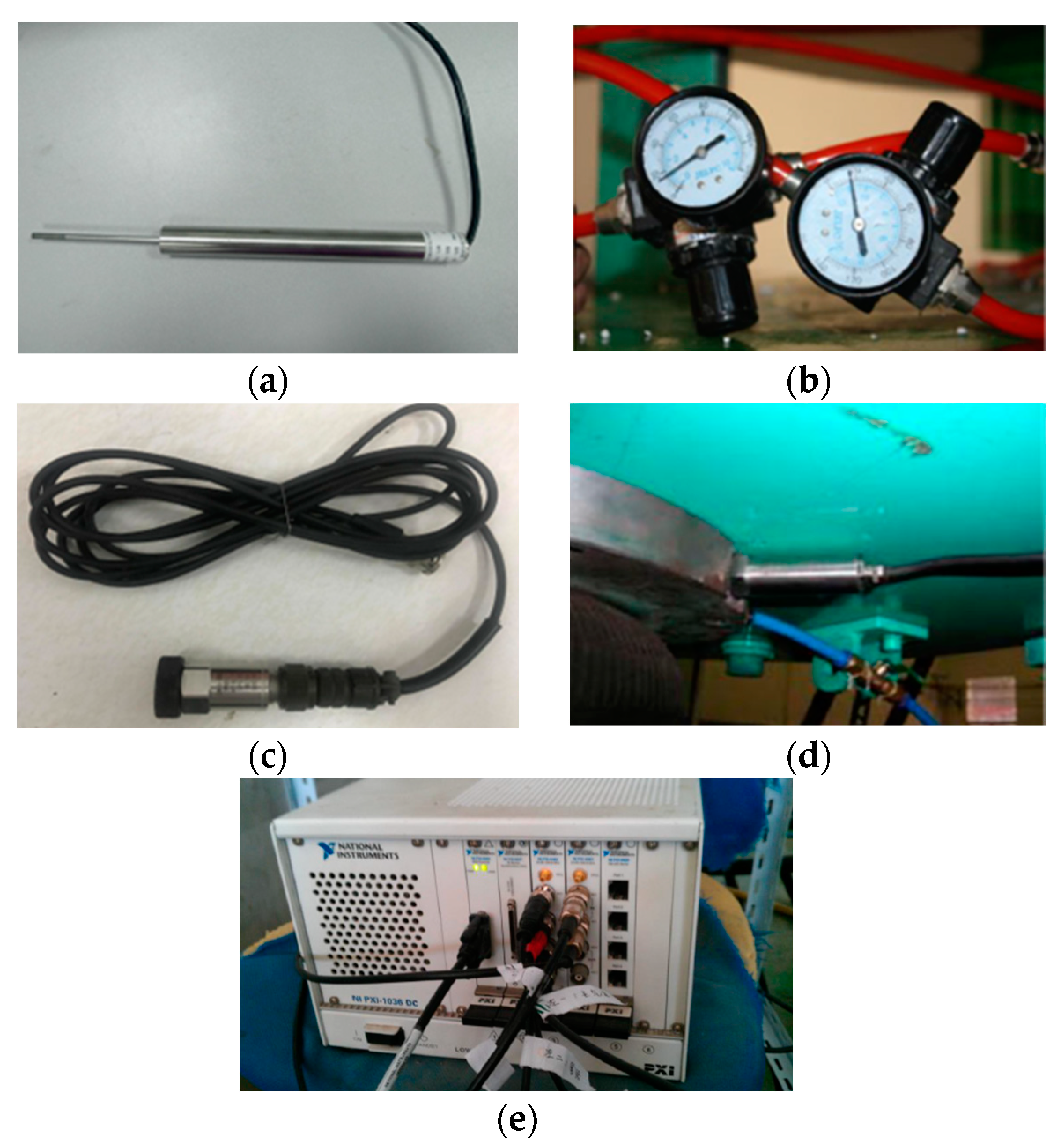
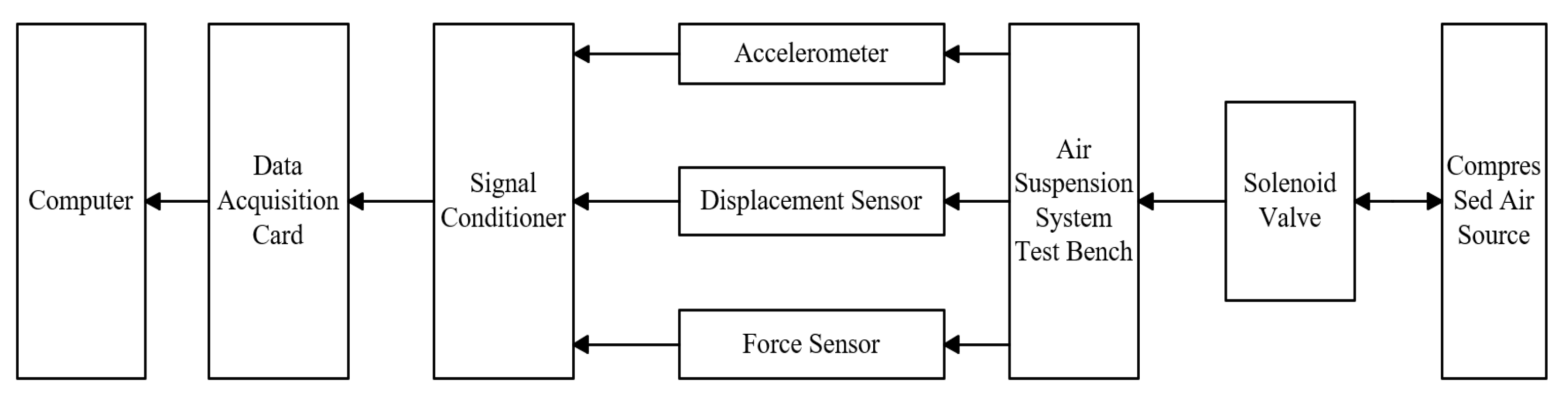
4.1. Air Suspension System Bench Test

A test bench for the air suspension system was designed and constructed for experimental research. The test system mainly consisted of a vibration excitation system, air spring force sensor, displacement sensor, pressure sensor, data acquisition system, air reservoir tank, controller, ball valve, etc. The test bench is shown in Figure 10. The test equipment for the bench test is shown in Figure 11.
The bench test system also includes auxiliary equipment, primarily consisting of pneumatic systems and electrical components such as pressure transmitters. The pneumatic system comprises elements like an air compressor, air reservoir, oil–water separator, and solenoid valves.
During the experiment, control of the air springs was achieved by opening and closing the solenoid valves. Data were tested and collected accordingly. The experimental procedure is illustrated in Figure 12.

4.2. Model Validation

The test parameters on the test bench were set to be the same as those in the simulation, and the simulation model was validated. A comparison between the simulated and experimental response curves of the air suspension is shown in Figure 13.
From Figure 13 it can be observed that due to the simplification of the system in the construction of the simulation model, factors such as the damping of the air spring itself and the stiffness of the damper were neglected. As a result, there exists a certain degree of error between the air suspension simulation curve and the test curve. However, the average error is small and within an acceptable range. The two curves basically coincide, and their trend is also essentially the same. This demonstrates the correctness and feasibility of the established air suspension model, and its simulation results have certain reference values for the analysis of active control strategies for air suspension.

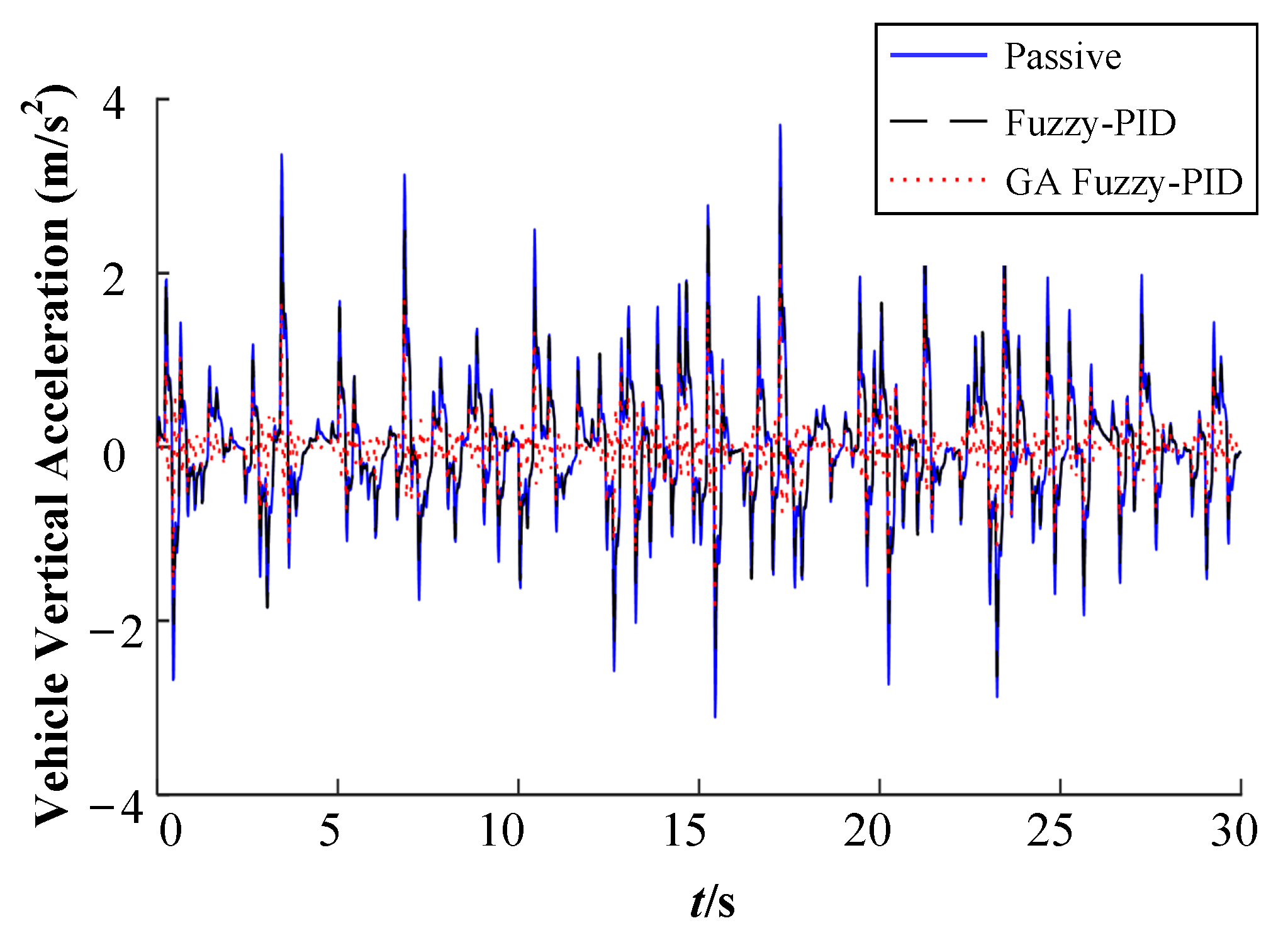
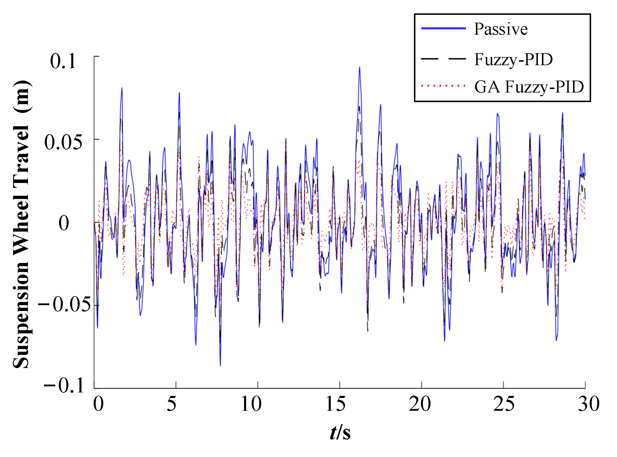
5. Simulation Analysis

Selected B-grade road surface, with a vehicle speed of 50 km/h, for conducting simulation analysis on the suspension model.
The genetic algorithm optimization was utilized to compare the fuzzy PID-controlled active and passive suspensions of the air suspension system before and after optimization. Figure 14, Figure 15 and Figure 16 depict the simulation results for vehicle vertical acceleration, suspension wheel travel, and dynamic tire load. The root mean square values and comparisons of each indicator are presented in Table 7.
When the vehicle speed is 50 km/h and subjected to B-class road surface excitation in the suspension model, as observed from Figure 14, the vertical body acceleration is 1.8062 m/s2. With the application of fuzzy PID control, the maximum acceleration attenuation decreases to 1.3908 m/s2. Furthermore, employing GA F-PID control further reduces the maximum acceleration to 1.2643 m/s2. According to Figure 15, the suspension travel is approximately 0.0337 m. With fuzzy PID control, this value decreases to 0.0276 m, and with GA F-PID control, it further decreases to 0.0249 m. Figure 16 indicates that the tire dynamic load is around 6.0895 kN. After applying fuzzy PID control, this load decreases to 5.7241 kN, and with GA F-PID control, it further decreases to 5.5414 kN.
From Figure 14, Figure 15 and Figure 16, it can be observed that the genetic algorithm-optimized fuzzy PID controller significantly reduces the vertical acceleration of the vehicle, suspension wheel travel, and dynamic tire load. After implementing the GA-fuzzy PID control strategy on the air suspension system, the response curves of the entire system become smoother, and the three performance indicators are optimized to some extent. The comfort, smoothness, and operational safety of the vehicle are also enhanced, achieving a relatively ideal control effect.
In order to comprehensively validate the effectiveness of the genetic algorithm-optimized fuzzy PID air suspension control, smoothness simulations were conducted in MATLAB under different road grades and at different speeds. The simulation results are shown in Table 7, Table 8 and Table 9.
From Table 7, Table 8 and Table 9, it can be observed that under the same conditions, compared to passive suspension, both fuzzy PID and GA-fuzzy PID controlled air suspensions show decreased values in suspension performance evaluation indicators, attenuating vehicle body vibrations and enhancing driving smoothness and ride comfort. Taking Grade B road surface as an example, fuzzy PID controlled air suspension, compared to passive air suspension, showed a decrease of 23%, 18%, and 6% in the root mean square values of vehicle vertical acceleration, suspension wheel travel, and dynamic tire load, respectively. Under the same experimental conditions, the evaluation indicator values corresponding to the genetic algorithm decreased by 30%, 26%, and 9%, respectively. Comparatively, the air suspension fuzzy PID control optimized by GA demonstrates more noticeable control effects and superior suspension performance, further improving the smoothness and comfort of the vehicle.

6. Conclusions

Combining the operational characteristics of air springs and the complex nonlinear properties of air suspension systems within the scope of vehicle ride comfort research, an analysis is conducted on the vertical dynamics of the vehicle. This involves simplifying the vehicle model and constructing a 1/4 two-degree-of-freedom vehicle model. Taking into account typical driving conditions, a mathematical model of random road input is established, and a road white noise model is built using MATLAB/Simulink. The study includes determining air suspension system parameters and ride comfort evaluation criteria for analyzing the ride comfort of the suspension system.
Integrating PID control methodology, the difference between the ideal vertical vibration acceleration (0) of the vehicle and the actual vibration acceleration is directly fed into the controller. The active control force of the air suspension system serves as the output. Using a trial-and-error method, the PID parameters are continuously adjusted based on control effectiveness to optimize their values. Eventually, the PID controller parameters are determined as follows: Kp = 1, Ki = 53, Kd = 0.1. In Simulink, combining the road input system, air suspension simulation module, and PID control system, a PID-controlled air suspension simulation model is established for simulation analysis.
Using fuzzy logic and PID control methods, PID parameters are dynamically optimized based on specific fuzzy rules. The integration of fuzzy reasoning with PID control adjusts parameter values according to system requirements to effectively manage the suspension system. The input signals to this controller are the vehicle’s vertical acceleration error e and its rate of change ec. Through processes such as fuzzy inference and parameter adjustment, the controller generates the final output. By adjusting the switching time of electromagnetic valves, the air pressure in the air springs is regulated to adjust the stiffness of the air suspension system, thereby determining the optimal PID parameter values.
Using genetic algorithms to optimize the control rules and membership functions of the F-PID controller, the performance indicators of active suspension vehicle body acceleration, suspension deflection, and tire load are normalized by their counterparts under the same conditions of passive suspension. This normalization forms the objective function for genetic algorithm optimization, where the reciprocal of the objective function serves as the fitness function. The genetic algorithm calls the F-PID controller model, with ride comfort indicators inputted as optimization parameters in the main GA program, to obtain the optimal values of F-PID controller parameters.
In MATLAB/Simulink, three different controllers were established to implement distinct air suspension control strategies, and the performance of the suspension system was studied through simulation. Time-domain response curves of the air suspension systems were obtained, comparing the effectiveness of fuzzy PID control with and without genetic algorithm (GA) optimization. Post-application of the control strategies, improvements were observed in various performance indicators of the air suspension system compared to the passive suspension. Specifically, the root mean square values of body acceleration, suspension travel, and tire dynamic load were reduced by 23%, 18%, 6%, and 30%, 26%, 9%, respectively, with fuzzy PID and GA-optimized fuzzy PID controls. Notably, the GA-optimized fuzzy PID control demonstrated superior numerical evaluation metrics, further lowering the root mean square values of body acceleration, suspension travel, and tire dynamic load, indicating enhanced control efficacy. This study addresses the limitations of traditional fuzzy PID parameter tuning and underscores the superiority of GA-optimized fuzzy PID control strategies for air suspension systems, offering valuable insights for optimizing active control of air suspensions.

Author Contributions

Conceptualization, S.Z. and M.L.; methodology, S.Z.; software, J.X.; vali dation, S.Z. and Z.W.; formal analysis, S.Z.; investigation, S.L.; resources, J.L.; data curation, S.Z.; writing—original draft preparation, S.Z.; writing—review and editing, M.L.; visualization, J.X.; supervision, S.Z.; funding acquisition, M.L. All authors have read and agreed to the published version of the manuscript.

Funding

This study was supported by Natural Science Foundation of Hainan Province, Grant No. 521RC497 & No. 2019RC144.

Institutional Review Board Statement

Not applicable.

Informed Consent Statement

Not applicable.

Data Availability Statement

Data are contained within the article.

Conflicts of Interest

The authors declare no conflicts of interest.

References

  1. Ming, M. Intelligent Manufacturing Technology of New Energy Vehicle Lightweight Chassis Suspension System. Mach. Build. Autom. 2021, 50, 224–226. [Google Scholar]
  2. Chao, L.Y. Suspension System Optimization and Study on Control of the Electric Vehicle. Master’s Thesis, Qingdao University of Science, Qingdao, China, 2018. [Google Scholar]
  3. Lei, S.S. Research on Control Strategy of Charging and Deflating Characteristics of Electronically Controlled Active Air Suspension. Master’s Thesis, Taiyuan University of Technology, Taiyuan, China, 2019. [Google Scholar]
  4. Rui, B. Nonlinear adaptive sliding-mode control of the electronically controlled air suspension system. Int. J. Adv. Robot. Syst. 2019, 16, 1729881419881527. [Google Scholar] [CrossRef]
  5. Nazemian, H.; Masih-Tehrani, M. Hybrid Fuzzy-PID Control Development for a Truck Air Suspension System. SAE Int. J. Commer. Veh. 2020, 13, 55–69. [Google Scholar] [CrossRef]
  6. Li, H.; Li, S.; Sun, W.; Wang, L.; Lv, D. The optimum matching control and dynamic analysis for air suspension of multi-axle vehicles with anti-roll hydraulically interconnected system. Mech. Syst. Signal Process. 2020, 139, 106605. [Google Scholar] [CrossRef]
  7. Nguyen, V.; Jiao, R.; Zhang, J. Control Performance of Damping and Air Spring of Heavy Truck Air Suspension System with Optimal Fuzzy Control. SAE Int. J. Veh. Dyn. Stab. NVH 2020, 4, 179–194. [Google Scholar] [CrossRef]
  8. Prassad, S.G.; Malar Mohan, K. A contemporary adaptive air suspension using LQR control for passenger vehicles. ISA Trans. 2019, 93, 244–254. [Google Scholar]
  9. Chen, Y.; Zhang, S.; Mao, E.; Du, Y.; Chen, J.; Yang, S. Height stability control of a large sprayer body based on air suspension using the sliding mode approach. Inf. Process. Agric. 2020, 7, 20–29. [Google Scholar] [CrossRef]
  10. Ma, X.F.; Li, K. The Simulation of Air Suspension System Based on PID Control Strategy. Autmobile Appl. Technol. 2017, 8, 142–145. [Google Scholar] [CrossRef]
  11. Anh, N.T. Control an active suspension system by using PID and LQR controller. Int. J. Mech. Prod. Eng. Res. Dev. 2020, 10, 7003–7012. [Google Scholar]
  12. Ab Talib, M.H.; Mat Darus, I.Z.; Mohd Samin, P.; Mohd Yatim, H.; Ardani, M.I.; Shaharuddin, N.M.; Hadi, M.S. Vibration control of semi-active suspension system using PID controller with advanced firefly algorithm and particle swarm optimization. J. Ambient. Intell. Humaniz. Comput. 2021, 12, 1119–1137. [Google Scholar] [CrossRef]
  13. Tian, M.; Nguyen, V. Control performance of suspension system of cars with PID control based on 3D dynamic model. Journal of Mechanical Engineering. Autom. Control. Syst. 2020, 1, 1–10. [Google Scholar]
  14. Shafiei, B. A Review on PID Control System Simulation of the Active Suspension System of a Quarter Car Model While Hitting Road Bumps. J. Inst. Eng. (India) Ser. C 2022, 103, 1001–1011. [Google Scholar] [CrossRef]
  15. Han, S.Y.; Dong, J.F.; Zhou, J.; Chen, Y.H. Adaptive fuzzy PID control strategy for vehicle active suspension based on road evaluation. Electronics 2022, 11, 921. [Google Scholar] [CrossRef]
  16. Bashir, A.O.; Rui, X.; Zhang, J. Ride comfort improvement of a semi-active vehicle suspension based on hybrid fuzzy and fuzzy-PID controller. Stud. Inform. Control 2019, 28, 421–430. [Google Scholar] [CrossRef]
  17. Zhang, P.; Yue, H.; Shi, Z.; Lin, J.; Chen, Z. A fuzzy pid algorithm-based attitude control method of suspension-type small rail vehicles. J. Vib. Eng. Technol. 2022, 10, 111–130. [Google Scholar] [CrossRef]
  18. Ilesanmi, D.; Khumbulani, M.; Adefemi, A.; Kazeem, B. The use of adaptive fuzzy-PID for vibration control in the suspension system of a railcar. In Proceedings of the 2020 IEEE 11th International Conference on Mechanical and Intelligent Manufacturing Technologies (ICMIMT), Cape Town, South Africa, 20–22 January 2020; pp. 130–134. [Google Scholar]
  19. Chen, G.; Lv, S.; Dai, J. Study on PID control of vehicle semi-active suspension based on genetic algorithm. Int. J. Innov. Comput. Inf. Control 2019, 15, 1093–1114. [Google Scholar]
  20. Wang, Y.; Chen, K.; Dong, M. Research on active suspension system of heavy commercial vehicle controlled by PID controller based on genetic algorithm. In Advances in Precision Instruments and Optical Engineering, Proceedings of the International Conference on Precision Instruments and Optical Engineering, Guangzhou, China, 20–22 August 2021; Springer Nature: Singapore, 2022; pp. 555–566. [Google Scholar]
  21. Mudduluru, S.R.; Chizari, M. Quarter and full car models optimisation of passive and active suspension system using genetic algorithm. arXiv 2021, arXiv:2101.12629. [Google Scholar]
  22. Rajamani, R. Vehicle Dynamics and Control; Springer: New York, NY, USA, 2011. [Google Scholar]
  23. GB 7031-1987; Vehicle Vibration Input—Road Flatness Representation. China Standard Press: Beijing, China, 1987.
Figure 1. 1/4 Two-Degree-of-Freedom Model of The Vehicle.
Applsci 14 07787 g001
Figure 2. Road Surface Model.
Applsci 14 07787 g002
Figure 3. Time domain curve of B road surface.
Applsci 14 07787 g003
Figure 4. PID Simulation System of Air Suspension.
Applsci 14 07787 g004
Figure 5. Schematic Diagram of Fuzzy PID Controller.
Applsci 14 07787 g005
Figure 6. Input membership function curve.
Applsci 14 07787 g006
Figure 7. Output membership function curve.
Applsci 14 07787 g007
Figure 8. The Basic Program of Genetic Algorithm.
Applsci 14 07787 g008
Figure 9. Fitness curve.
Applsci 14 07787 g009
Figure 10. Experimental device of suspension.
Applsci 14 07787 g010
Figure 11. Experimental device of suspension. (a) Displacement sensor. (b) The barometer. (c) Acceleration sensor. (d) Pressure transducer. (e) NI data acquisition instrument.
Applsci 14 07787 g011
Figure 12. Block diagram of air suspension test bed.
Applsci 14 07787 g012
Figure 13. Comparison of response curves between simulation results and test results.
Applsci 14 07787 g013
Figure 14. Simulation of vehicle vertical acceleration.
Applsci 14 07787 g014
Figure 15. Simulation of suspension wheel travel.
Applsci 14 07787 g015
Figure 16. Simulation of dynamic tire load.
Applsci 14 07787 g016
Table 1. Part of the structural parameters of the vehicle.
NameNotationValue
Sprung massm2/kg500
Unsprung massm1/kg50
Suspension dampingc/N·s·m−11700
Tire stiffnesskt/N·m−1200,000
Table 2. Relationship between PID regulating parameters and performance indexes.
ParametersRise TimeOvershootSetting TimeSteady-State Error
KpDecreaseIncreaseSlight ChangeDecrease
KiDecreaseIncreaseIncreaseEliminate
KdSlight ChangeDecreaseDecreaseSlight Change
Table 3. Fuzzy control logic of ΔKp.
eec
NBNMNSZOPSPMPB
NBPBPBPMPMPSZOZO
NMPBPBPMPSPSZONS
NSPMPMPMPSZONSNS
ZOPMPMPSZONSNMNM
PSPSPSZONSNSNMNM
PMPSZONSNMNMNMNB
PBZOZONMNMNMNBNB
Table 4. Fuzzy control logic of ΔKi.
eec
NBNMNSZOPSPMPB
NBNBNBNMNMNSZOZO
NMNBNBNMNSNSZOZO
NSNBNMNSNSZOPSPS
ZONMNMNSZOPSPMPM
PSNMNSZOPSPSPMPB
PMZOZOPSPSPMPBPB
PBZOZOPSPMPMPBPB
Table 5. Fuzzy control logic of ΔKd.
eec
NBNMNSZOPSPMPB
NBPSNSNBNBNBNMPS
NMPSNSNBNMNMNSZO
NSZONSNMNMNSNSZO
ZOZONSNSNSNSNSZO
PSZOZOZOZOZOZOZO
PMPBPSPSPSPSPSPB
PBPBPMPMPMPSPSPB
Table 6. Genetic algorithm parameters.
ParametersExplanationParametersExplanation
Encoding MethodBinary EncodingMutation FunctionConstrained Adaptive Mutation
Initial PopulationRandomly Generate Within Specified BoundsCrossover Probability0.9
Population Size30Mutation Function0.1
Selection FunctionRandom Uniform SelectionMaximum Evolution Generations100
Crossover FunctionDiversified CrossoverStopping Generation100
Table 7. Test conditions of A-grade road surface at 70 km/h.
Evaluation CriteriaPassive SuspensionFuzzy PIDGA-Fuzzy PIDPercentage of Fuzzy PID OptimizationPercentage of GA-Fuzzy PID Optimization
Vehicle Vertical Acceleration
(m/s2)
1.04730.81690.754122%28%
Suspension Wheel Travel
(m)
0.01560.01290.011717%25%
Dynamic Tire Load
(kN)
4.34544.12814.04125%7%
Table 8. Test conditions of B-grade road surface at 50 km/h.
Evaluation CriteriaPassive SuspensionFuzzy PIDGA-Fuzzy PIDPercentage of Fuzzy PID OptimizationPercentage of GA-Fuzzy PID Optimization
Vehicle Vertical Acceleration
(m/s2)
1.80621.39081.264323%30%
Suspension Wheel Travel
(m)
0.03370.02760.024918%26%
Dynamic Tire Load
(kN)
6.08955.72415.54146%9%
Table 9. Test conditions of C-grade road surface at 40 km/h.
Evaluation CriteriaPassive SuspensionFuzzy PIDGA-Fuzzy PIDPercentage of Fuzzy PID OptimizationPercentage of GA-Fuzzy PID Optimization
Vehicle Vertical Acceleration
(m/s2)
2.76382.07291.907025%31%
Suspension Wheel Travel
(m)
0.06110.04890.044620%27%
Dynamic Tire Load
(kN)
8.83788.39598.13085%8%
Disclaimer/Publisher’s Note: The statements, opinions and data contained in all publications are solely those of the individual author(s) and contributor(s) and not of MDPI and/or the editor(s). MDPI and/or the editor(s) disclaim responsibility for any injury to people or property resulting from any ideas, methods, instructions or products referred to in the content.

