Article

The Process Optimization Analysis of CBN Abrasive Cu-Sn-Ti Coating Fabrication via the Ultrasonic-Vibration-Assisted Laser Cladding Method

1
School of Mechanical Engineering and Automation, Northeastern University, Shenyang 110819, China
2
Liaoning Provincial Key Laboratory of High-End Equipment Intelligent Design and Manufacturing Technology, Shenyang 110819, China
*
Authors to whom correspondence should be addressed.
Appl. Sci. 2024, 14(17), 7790; https://doi.org/10.3390/app14177790
Submission received: 19 July 2024 / Revised: 14 August 2024 / Accepted: 21 August 2024 / Published: 3 September 2024
(This article belongs to the Special Issue Precision Manufacturing Technology)

Abstract

:
Ultra-precision machining has higher requirements for the performance of abrasive tools, but the traditional grinding wheel has some problems such as irregular grain arrangement, limited chip space, and high grinding temperature. Therefore, a structured grinding wheel suitable for ultra-precision machining is proposed. In this study, the laser cladding method and ultrasonic vibration technology were combined to study the preparation process of a structured grinding wheel. Firstly, the quality evaluation system of the printing layer was established, and the shape coefficient and dilution rate were used to evaluate the laser cladding quality. The effects of laser power, sweep speed, powder feeding speed, and ultrasonic power on the shape coefficient and dilution rate of the printing layer were analyzed by single-factor experiments. The level range of each factor in the orthogonal experiment was established to optimize the process parameters. The surface morphology was observed, and the influence of ultrasonic vibration on the morphology was analyzed. The structured grinding wheel was prepared according to the optimized parameters.

1. Introduction

With the increasingly demanding working conditions such as load and high temperature during ultra-precision machining, higher requirements are put forward for high-performance abrasive tools [1,2,3,4]. The irregular grain arrangement of the traditional grinding wheel is not conducive to improving the grinding performance of the wheel. Therefore, a structured grinding wheel is proposed. It has a good coolant delivery capacity, which can reduce the grinding temperature and achieve ultra-smooth surface generation. Therefore, many scholars have studied the preparation technology of the structured grinding wheel.
Stepien et al. [5] were the first to study microstructure surface machining with a macrostructured grinding wheel, and proposed several classic structured surface machining methods. Silva et al. [6,7] used a dressing tool to process the macrostructure on the surface of a grinding wheel, and then used it to process the structured surface. Mao et al. [8] studied a kind of micro-grooved grinding wheel used for grinding narrow and deep grooves, which can effectively improve the bearing capacity of coolant in the grinding zone. The effect of the micro-groove structure on grinding wheel wear was evaluated through the comparative experiment of grinding narrow and deep grooves, and the wear behavior of the orderly micro-groove grinding wheel was clarified. Through the testing of grinding force, force ratio, and other parameters, it has been verified that the ordered micro-grooved grinding wheel can realize self-sharpness and ensure good grinding performance. In order to determine the influence of structural parameters of the structured grinding wheel on grinding force, Yi et al. [9] determined the critical cutting depth of plow and cutting transition through a single scraping experiment, and analyzed the relevant parameters of the grinding process. A surface morphology model of the structural grinding wheel and a grinding force model of a single grain during the ploughing stage was established. A grinding force calculation model of a straight-groove-structured wheel was established and verified by a grinding experiment. The results showed that the calculated grinding force was in good agreement with the experimental values, and that the groove width has little effect on the grinding force when the intermittent ratio of the structured grinding wheel is constant. However, when the groove width is unchanged, the intermittent ratio has a great influence on the grinding force, and the grinding force decreases obviously with the increase of the intermittent ratio.
Mao et al. [10] proposed a new form of macrostructure grinding wheel, namely, a large spiral angle groove wheel (LSG-GW, β > 85°) and a large spiral angle spoiler groove wheel. A flow field model of the LSG-GW considering the channel parameters and an analysis model of the gas–liquid two-phase field were established. The results showed that increasing the groove width, groove depth, and spiral angle can reduce the pressure of the flow field in the air barrier layer and make the grinding liquid enter the grinding contact zone more easily. Through the analysis of the theoretical model of convective heat transfer co-distribution in heat transfer channels, it was found that the flow disturbance structure can bring more grinding fluid into the grinding contact area and significantly improve the convective heat transfer coefficient in the grinding contact area.
Chen et al. [11] proposed a new type of laser ablative veinlike structured grinding wheel (VLSGW). The venous structure can effectively reduce the flow resistance. Four biomimetic vein channels were ablated on the grinding wheel by a picosecond pulsed laser. The effects of the VLSGW on air return and workpiece surface pressure were analyzed by simulation. The grinding performance of SiC grinding with a VLSGW and an unstructured grinding wheel was compared. Compared with the USGW, the VLSGW can effectively reduce the normal and tangential grinding forces. At the same time, the VLSGW has better workpiece surface topology and wear resistance than the USGW.
Based on the principle of grinding kinematics and the topology of point sets, Lyu et al. [12] proposed a topological mapping grinding method for structured concave surfaces. In the study, a topological space consisting of a workpiece and grinding wheel was established, and the topological features of the structural pits and grinding wheel were extracted. The topological mapping equation of the grinding process was established, and the structural grinding wheel was designed according to the topological mapping equation. Finally, according to a grinding geometry simulation, the influence of grinding parameters on the surface topography of the pits was studied, and grinding experiments were carried out.
Monier et al. [13] studied the influence of the geometric parameters of a structured grinding wheel on the geometry of a structured surface during grinding. Firstly, the geometric parameters of the structured grinding wheel were determined. The synthetic geometric parameters of the structure surface were calculated, and the numerical and simulation models of the structured grinding wheel and grinding process were established according to the relevant working conditions. The results showed that the geometric parameters of each wheel affected the geometry of the structure surface at different rates. Grinding experiments were carried out, and the results showed that there was significant compatibility between the predicted surface and the machined surface, reflecting the accuracy of the proposed method for machining structured surfaces by grinding.
Zhou et al. [14] proposed a grinding surface microstructure method based on structured grinding wheels. Wire Electrical Discharge Machining (WEDM) technology was used to carry out structured dressing on the surface of a grinding wheel. The microstructure of a sapphire surface was ground with the structured grinding wheel after dressing. The effects of grinding speed, grinding depth, and feed rate on the surface roughness at the bottom of the micro-grooves in sapphire under both up-grinding and down-grinding conditions using structured grinding wheels were investigated. The results showed that the surface morphology of the micro-grooves after grinding remained intact, and the surface quality from down-grinding is better than that of up-grinding.
Fan et al. [15] studied the law of the influence of the grinding force of an ordered grinding wheel on workpiece surface geometry. Firstly, according to the parameters of the ribbed drag-reducing surface, a misaligned grinding wheel that can realize the machining of the ribbed drag-reducing surface was designed. Secondly, a simplified model of the grinding process of the rib-reducing surface was established, and a mechanical simulation of the workpiece surface morphology was carried out based on the finite element method. Finally, the influence of grinding speed, grinding depth, grain angle, and layout parameters on the surface geometry of the rib was studied, and the relationship between grinding force and surface topography was comprehensively discussed. In order to analyze the influence of grinding process parameters on the reflection effect, Chen et al. [16] carried out a theoretical exploration of the grinding process and workpiece surface topography of a grooved structured wheel with a large spiral angle. A macroscopic mathematical model and a microscopic particle random distribution model of the large spiral angle grooved grinding wheel were established, and the cutting process of the chip-cutting edge of the grinding wheel was deduced and calculated. Based on a model of the mechanism involved in grinding surface macro profile generation, the numerical mapping relationship between the spiral groove control parameters and process parameters and the reflection effect coefficient was calculated. The surface morphology of the workpiece after theoretical grinding was observed and compared with that of the workpiece after the actual grinding of the spiral groove grinding wheel. Wang et al. [17] proposed a method of planar topological mapping for grinding structured surfaces in order to obtain an array of trailing wave pits. Based on point-set topology theory, topological feature analysis and feature parameter extraction were carried out on the trailing wave element and arrangement. Combined with the mechanism of pitted surface grinding, the topological space-mapping relationship between the grinding wheel and the workpiece was established in the grinding process, and a grain-cluster structured grinding wheel was designed. MATLAB software was used to simulate and analyze the trailing wave surface grinding process. The influence law of related parameters was obtained, and the grinding of the structured surface was realized through a grinding test. In order to obtain a structured reticulated surface, Zhang et al. [18] designed a grinding wheel with an end face with a grain sequence arrangement and established a kinematic equation of the grinding grain. The surface topography of the grinding grain was obtained by computer simulation, and the influence law of the grain arrangement parameters and grinding parameters of the grinding wheel on the surface texture topography was discussed. The results indicate that the relative positioning of the grinding wheel and workpiece has a significant impact on the surface topography. By increasing the rotational speed of the grinding wheel and reducing the leaf sequence coefficient, a more uniform surface can be achieved.
Wen et al. [19] used synthetic diamond as an abrasive, bronze binder as a binder, and molybdenum disulfide and titanium dioxide nanoparticles with a certain mass fraction as filling materials to prepare a bronze binder self-lubricating diamond wheel. The abrasive wear of the diamond wheel during the grinding of ceramic materials is reduced, and the quality of the machining surface is improved. A new self-lubricating diamond wheel with a bird-feather structure was obtained by using a pulsed laser to ablate the designed bird-feather structure, reducing the geometry on the surface of the diamond wheel. The results show that the addition of nanoparticles does not reduce the mechanical properties of the grinding wheel, the ablative quality of the grinding wheel surface is higher, and the non-ablative area is not affected. Hou et al. [20] proposed a new method to make grooves with diamond cutting tools to manufacture structured grinding wheels with U-shaped grooves. The diamond cutting tools, chip, and groove structure were examined by SEM and EDS. No significant cracks were found on the sides and bottom of the groove, and the width of the groove was close to the thickness of the tools. A grinding test of the grooved grinding wheel was carried out and compared with that of an ungrooved grinding wheel. The grooved wheel was found to reduce the grinding force and grinding temperature and eliminate workpiece burns.
Deng et al. [21] conducted research on diamond grinding wheels with a regular hexagonal structure, strong hydrophilicity, and high wear resistance. A new laser structure technology based on the coordinated control of focusing position and scanning times was proposed, which can effectively produce hexagonal structures with a small angle and a depth of a few millimeters on the surface of the grinding wheel. The results showed that, compared with the unstructured grinding wheel, the hydrophilicity of the structured grinding wheel was significantly improved; its surface hydrophilicity increased with the increase in structural distance and depth, and the grinding peak temperature and surface damage were also effectively reduced. Hou et al. [22] proposed a new grooving method using a reciprocating laser scanning strategy combined with alternating forward and backward trajectories. The ablation effects of an ultrafast laser on an abrasive, ceramic bond and an SA90JV grinding wheel were studied from the angle of groove shape. The results showed that, compared with sequential scanning, reciprocating scanning can achieve a U-shaped groove profile and a high material removal rate.
Laser cladding technology has advantages in the field of CBN grinding wheel preparation, such as a high material utilization rate, short manufacturing cycle, and green environmental protection [23]. In addition, the grinding wheel prepared by the laser cladding method is easy to structure, and the interface joint can realize chemical metallurgical combination, increase the holding force of the abrasive particles, and effectively improve the service life of the grinding wheel. Ultrasonic-vibration-assisted laser cladding technology can overcome production barriers that the traditional grinding wheel sintering process cannot. With ultrasonic assistance, the CBN particles can produce high-frequency fine vibrations in the molten pool, so as to achieve the orderly arrangement of the particles in the three-dimensional plane. In addition, the effects of ultrasonic vibration can refine the grain and improve the mechanical properties of the grinding layer.
In this paper, the optimal level range of each process parameter (ultrasonic power, laser power, sweep speed, powder feeding speed) was determined by a single-factor single-channel sweep experiment, and then an orthogonal experimental analysis was carried out. Variance and range analyses of the orthogonal experiment results were carried out to provide the optimal process parameters for grinding wheel preparation.

2. Fabrication Method and Experiments

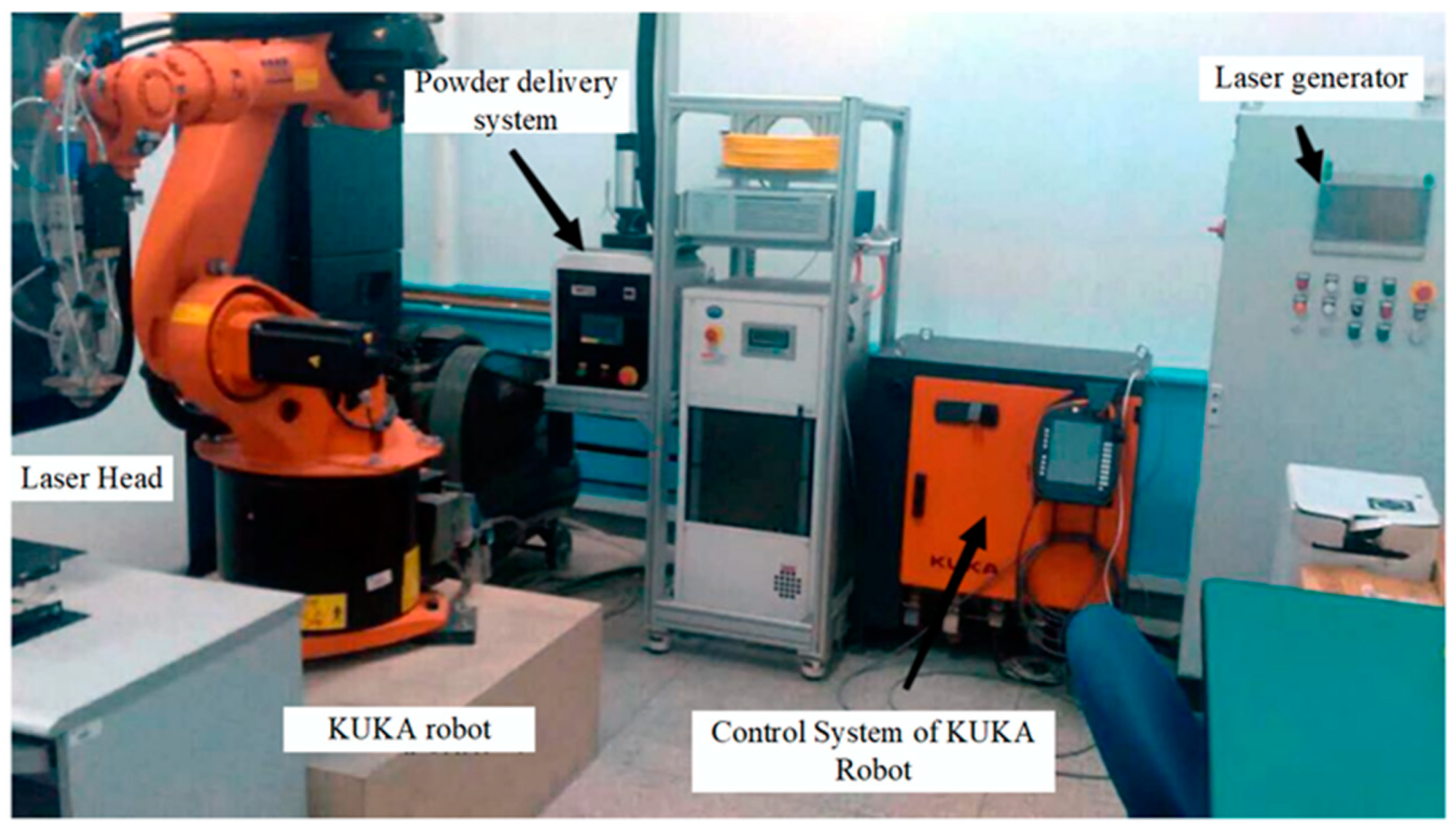
2.1. Experimental Equipment

The laser cladding equipment used in this study is shown in Figure 1, including a KUKA robot, laser generator, laser head, powder-feeding system, and protective gas system. The ultrasonic system includes an ultrasonic generator, amplitude converter, and transducer. Table 1 lists the specific parameters. The robot arm used in this experiment is the KUKA ZH30/60III, (KUKA Robotics Co., Ltd., Augsburg, Germany.) which is an intelligent robot that can be linked with six axes. The RaychamRC52 laser head (Nanjing Zhongke Raycham Laser Technology Co., Ltd., Nanjing, China) is installed at the end of the arm, and the IPG YLR-500 fiber laser (IPG Photonics Corporation, Oxford, MS, USA) is equipped with a maximum power of 500 W.

2.2. Fabrication Materials

The end-face-structured CBN grinding wheel prepared by ultrasonic-assisted laser cladding technology is divided into two parts: a printing layer and a matrix. The printing layer is composed of CBN grain and a copper-based binder. The purpose of fabricating a structured grinding wheel using ultrasonic-assisted laser cladding technology is to achieve chemical metallurgical bonding between the printing layer and the matrix. Compared with the traditional grinding wheel manufacturing method, it improves the holding force of the binder on the abrasive particles. The method of structuring is changed to reduce the thermal stress in the manufacturing process. The residual stress of the printed part is reduced and the grinding performance of the grinding wheel is enhanced.
The selection of abrasive particles must first consider their strength, particle size, crystal type, and surface conditions. Next, it is necessary to consider the oxidation of abrasive particles under the action of a laser heat source. The hardness of CBN is second only to diamond, and the thermal stability is stronger than diamond. The wear resistance is four times that of traditional abrasives, while having good thermal conductivity. Therefore, in this study, the Funnike CBN-980T abrasive particle (Funik Superhard material Co., Ltd., Zhengzhou, China) was selected; its surface was plated with titanium, and the particle size was 100–120 mesh.
In the process of laser cladding, in order to ensure that the binder can be uniformly and completely covered on the matrix, it is necessary to make a reasonable choice of matrix materials and properties. The matrix needs to have sufficient strength to avoid cracking and crushing during grinding due to the high-speed rotation of the grinding wheel. In addition, considering the economy of the selected base material, 45 steel was finally determined as the matrix material for the ultrasonic-vibration-assisted laser cladding for preparing the grinding wheel.
If the melting point of the metal bond is too low, it will affect its bonding strength with the grinding wheel matrix, resulting in the CBN particle falling off during grinding. This will not only affect the grinding effect, but also reduce the service life of the grinding wheel. If the melting point of the bond is too high, it will make the grinding wheel formation process difficult to control. The metal bond should also have good wettability for the CBN particles [24] to fully fill the gap between the CBN abrasive particles and the 45 steel abrasive wheel matrix, and improve the holding power of the abrasive particles. Due to the nature of CBN particles, they are difficult to wet using ordinary metal materials, and materials containing active elements are usually used as grinding wheel bonds. At the same time, the strength and hardness of the binder should meet the subsequent grinding requirements [25]. To prevent the rapid wear of the bond layer in the grinding process and extend the service life of the grinding wheel, in this study, spherical Cu-Sn-Ti alloy was selected as the binder with a particle size of −100−+250 mesh. The mass fraction of each element is shown in Table 2.

2.3. Quality Evaluation Parameter

In order to evaluate and optimize the influence of the laser cladding process parameters on the quality of the printing layer, a printing layer quality evaluation system was established. Figure 2 shows a schematic diagram of the melt pool of the printing layer.

2.3.1. Shape Factor γ

The shape factor of the melt pool is defined as the ratio of the melt pool width to the forming height:
γ = B H
The shape factor γ directly reflects the spreading state of the powder layer on the surface of the matrix. Generally speaking, when the shape coefficient γ 2 , the printing layer and the matrix will have a better combination of topography. The larger the width and the lower the height, the better the quality.

2.3.2. Dilution Rate η

The purpose of laser cladding is to use a laser as a heat source to print alloys with special properties on the surface of the matrix, forming a strong metallurgical bond with the matrix while maintaining a low dilution rate. A lower dilution rate η can avoid the influence of the matrix material on the performance of the cladding layer. The dilution rate η is also a description of the cross-section morphology of laser cladding coatings.
The dilution rate for laser cladding is:
η = A 2 A 1 + A 2 = h H + h
where A 1 is the printing layer cross-section area; A 2 is the cross-section area of the melting matrix; H is the melt height; and h is the melt depth of the matrix.
Since the dilution rate has a great influence on the properties of the cladding layer, the ratio h / H of the depth of the melt pool on the surface of the matrix material h to the height of the cladding layer H is a very important value to judge the dilution rate. An excessive dilution rate will increase the impurities entering the print layer, reduce the performance of the print layer, and increase the possibility of deformation and even cracking. If the dilution rate η is too low, it is difficult to form a solid chemical metallurgical bond between the printing layer and the matrix, and the printing layer can easily fail. Usually, the dilution rate should be controlled in a reasonable range (2–10%) according to the powder material. A reasonable selection of process parameters can obtain the appropriate dilution rate [26,27].

3. Effects of Process Parameters on the Performance of the Printing Layer
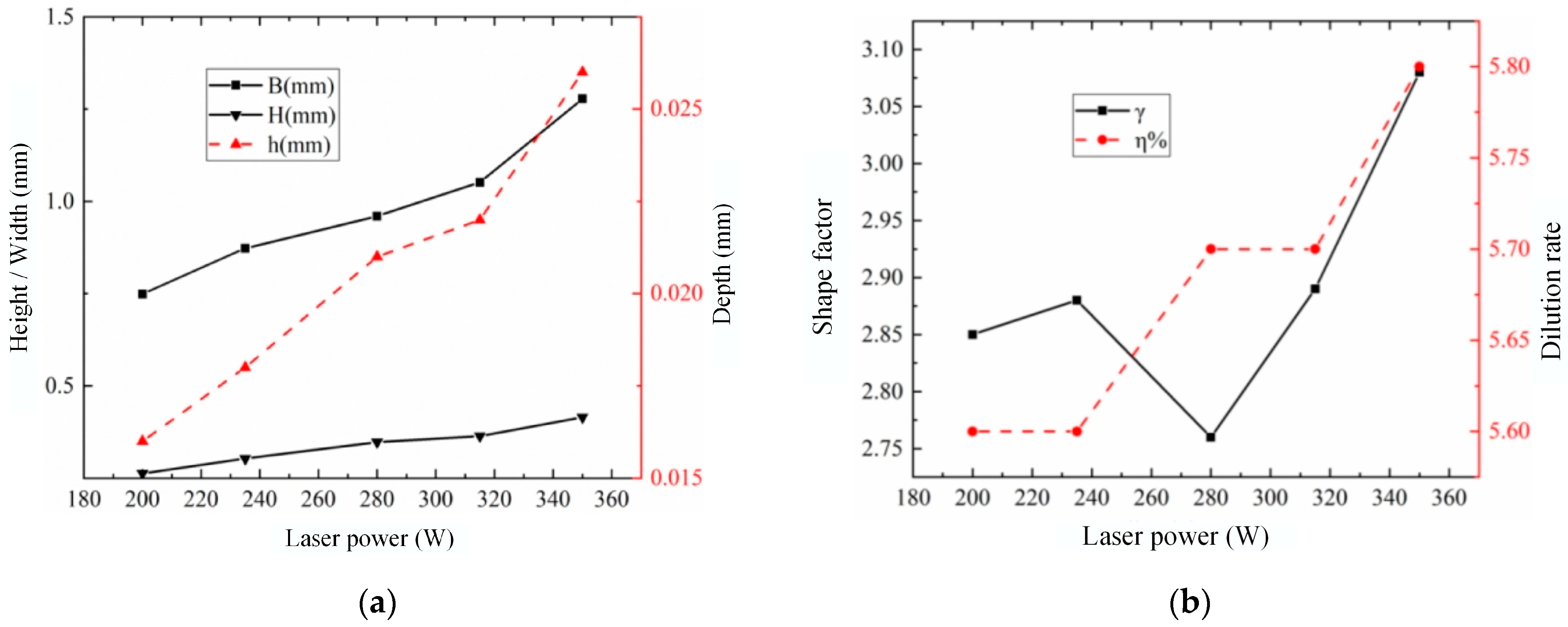
3.1. Laser Power

In order to optimize the process parameters, it is necessary to explore the influence of each parameter on surface quality. The level values of laser power Pl, sweep speed vs, powder feeding speed vr, and ultrasonic power percentage Ps were determined through single-factor experiments. The single-factor experimental design and result analysis under different laser powers are shown in Table 3.
From Figure 3a, it can be seen that as the laser power gradually increases, the melt width B and the melt height H both increase, which indicates that the higher the laser power, the deeper the matrix melts. This indicates that as the laser power increases, the heat-affected zone gradually expands. In Figure 3b, it can be seen that the dilution ratio is around 5%, and the shape coefficient γ is also greater than 2, which indicates that the combination of the printing layer is relatively good.
When the laser power is higher, the sintering temperature has already exceeded the stable limit of CBN, which will inevitably lead to a decrease in the quality of the formed part. After observation and analysis, it was found that the cladding layer had a relatively regular shape in the experiments with a laser power of 200 W and 235 W, and the shape coefficient of the 235 W parameter was higher. Therefore, it can be determined that the most appropriate laser parameter level is around 235 W. The final determined laser power levels are 220 W, 235 W, and 250 W.

3.2. Sweep Speed

Table 4 shows the single-factor experiment design and results for sweep speed. In cases where the other three parameters remain unchanged, a too-fast sweep speed will shorten the dwell time of the laser on the mixed powder, and the energy absorbed by the powder layer will decrease. This will inevitably lead to irregular and discontinuous defects in the cladding pool. A too-low sweep speed may cause the powder layer to absorb a large amount of excess energy, forming a flake-like morphology, which affects the cladding quality.
As shown in Figure 4a, it is not difficult to see that as the sweep speed gradually increases, the melt width B and melt height H both decrease, and the melt depth h also decreases. This means that when the other three parameters are fixed and the sweep speed is relatively slow, the dwell time of the laser spot on the same area increases, and the heat accumulation will inevitably increase, causing more powder melting and the expansion of the heat-affected zone.
As shown in Figure 4b, the dilution ratios of all experimental groups meet the requirements, but the shape coefficient with a sweep speed of 3 mm/s is too low, indicating a poor surface bonding effect. Although the shape coefficient of group 2 meets the requirement of greater than 2, its surface bonding effect is not good due to its proximity to the boundary. Therefore, after comprehensive consideration, it is advisable to have a sweep speed of above 4 mm/s. The level values for this parameter are selected as 5 mm/s, 6 mm/s, and 7 mm/s.

3.3. Powder Feeding Speed

Table 5 presents the experimental design and result analysis regarding the powder feeding speed. As shwon in Figure 5, with the remaining three process parameters unchanged, the increase in the powder feeding speed leads to an increase in powder output at the same time, resulting in a decrease in melt width B and an increase in melt height H, while the melt depth h remains basically unchanged. This is because when the energy absorption is not saturated, many powders will melt, resulting in an increase in H. After saturation, the height H will stabilize within a certain range. It can be seen that H has stabilized in groups 3, 4, and 5, and the shape coefficients of these three groups have also stabilized between 2.8 and 2.9. The dilution ratio η meets the requirements. Therefore, the level values for determining the powder feeding speed are 1.7 r/min, 1.8 r/min, and 1.9 r/min.

3.4. Ultrasonic Power

The experimental design and result analysis are shown in Table 6 and Figure 6. Under the action of ultrasonic vibration, the melt pool of experimental groups 2–4 was relatively uniform, with no significant changes in width B and height H. The melt depth increased slightly, which is a result of the thermal effect of ultrasonic vibration and other factors. Thus, the selected ultrasonic vibration power level values are 5%, 10%, and 15%.
The level values of each factor established in the single-factor experiment are shown in Table 7.

4. Process Optimization and Analysis

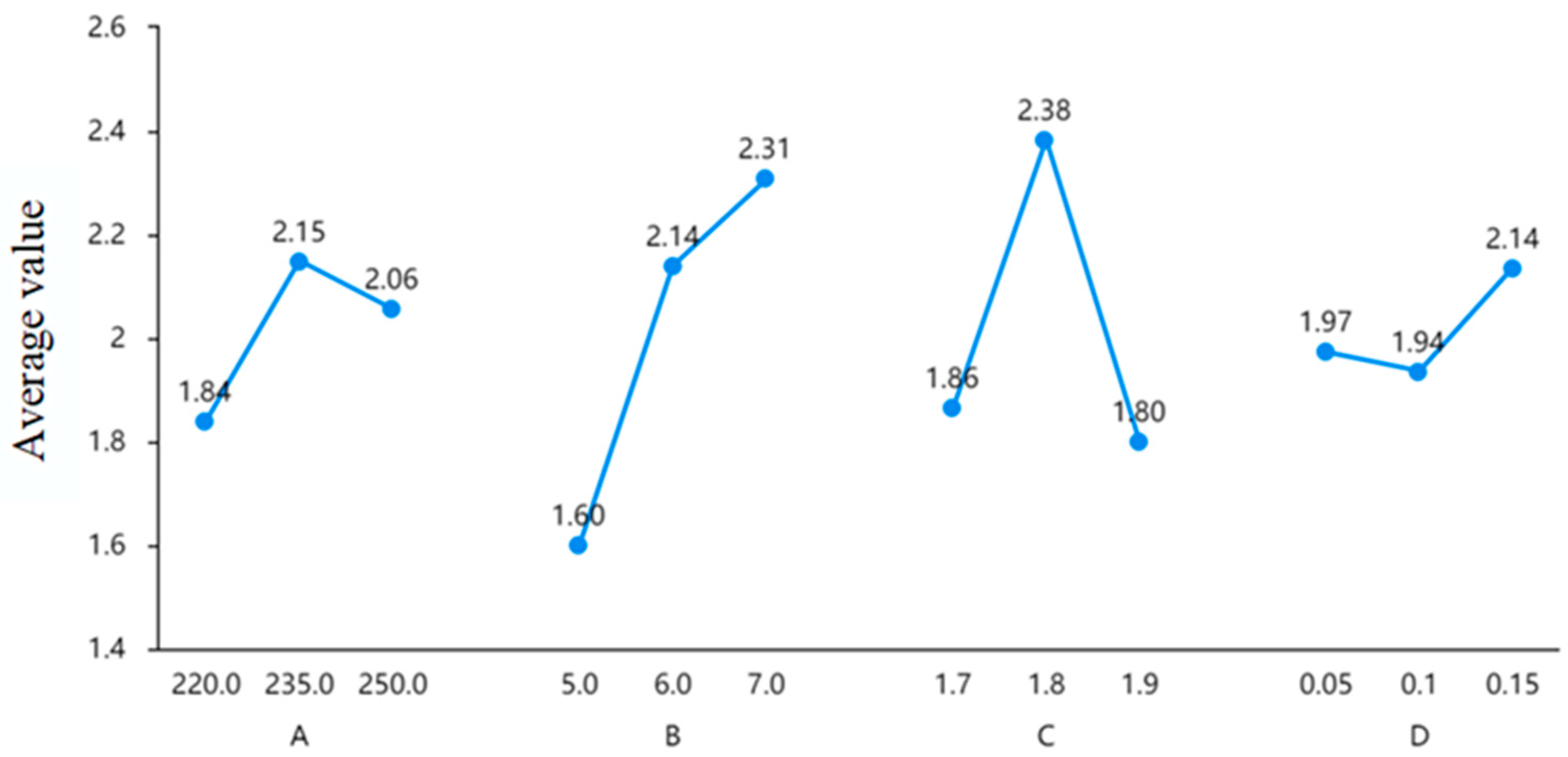
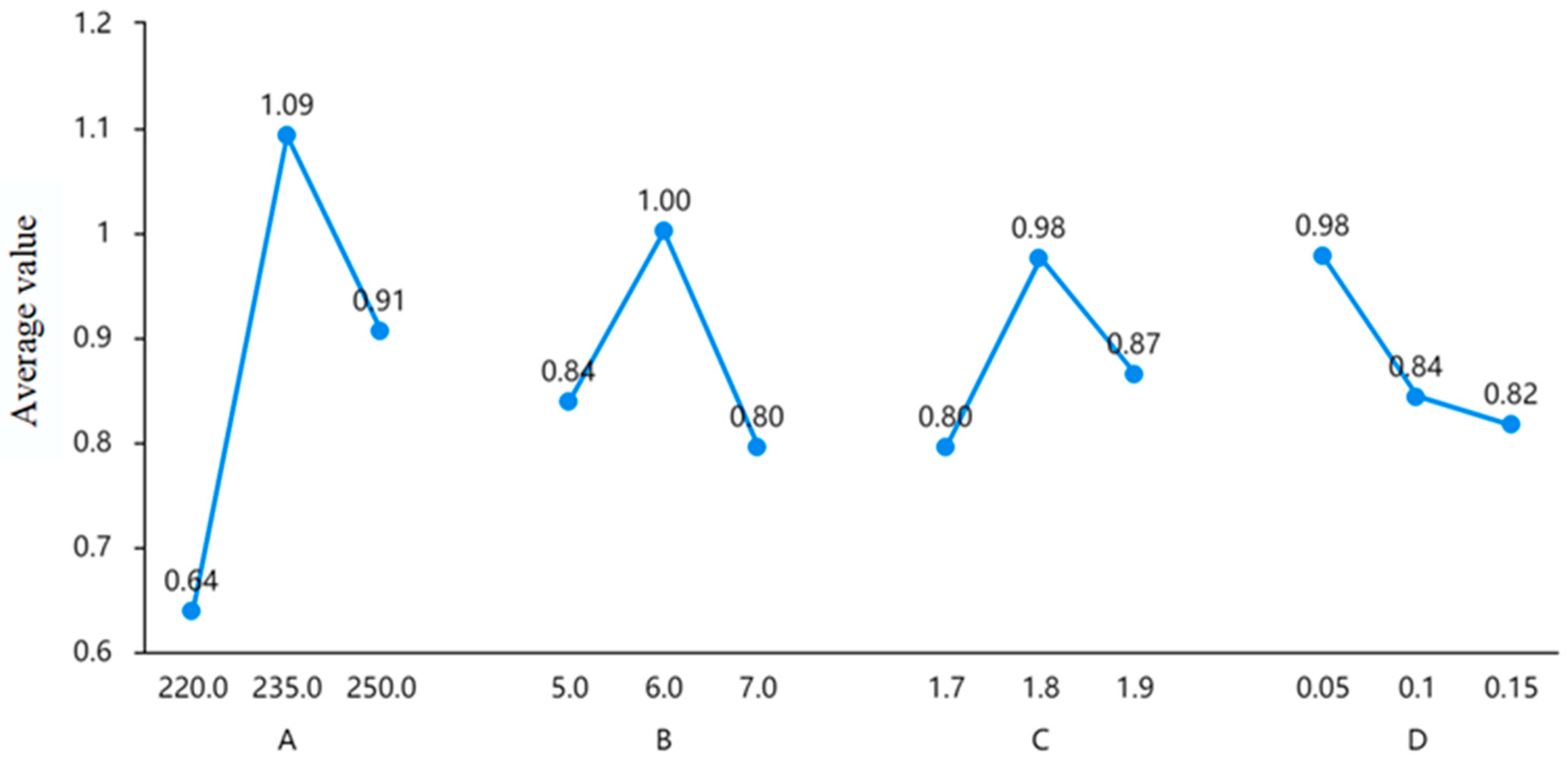
4.1. Orthogonal Experiment Design and Range Analysis

The orthogonal experiment and the experimental results are shown in Table 8. The range analysis results are shown in Table 9, Table 10 and Table 11.
The K value in the range analysis table is the sum of the experimental data for a certain factor at a certain level, while the K avg value is the average value of the corresponding K. The R is the difference between the maximum and minimum values of the mean. The size of R reflects one factor that has the most significant impact on the shape coefficient γ. The larger the R, the greater the impact. The smaller the R, the more stable it is, and the less significant the impact.
As shown in Table 9, compared to the influence of various factors on the shape coefficient γ, the sweep speed (B) has the most significant impact, followed by the powder feeding speed (C), and then the laser power (A). However, the size of the ultrasonic power has no significant effect on the shape coefficient γ.
Figure 7 shows the intuitive level graph of various factors’ K avg, which shows that, for the shape coefficient, the effects of laser power (A) and powder feeding speed (C) on the shape coefficient γ show a trend of first increasing and then decreasing. The influence of factor B, which is the sweep speed on the shape coefficient, gradually increases. The influence of ultrasonic power percentage (D) is basically maintained within a certain range, with little fluctuation.
Table 10 shows the range analysis of various factors on the width B of the melt pool. Through the comparison of R values, the factor that has the greatest impact on the width of the melt pool is laser power (A), while the other three factors have no significant impact on the width B.
From Figure 8, it can be seen that the first three factors have an increasing and then decreasing trend on width B, indicating that the best advantage is covered in the middle section. The ultrasonic power percentage consistently decreases, but the decrease is not significant and tends to flatten out in the later stages.
Table 11 shows the range analysis of the height H. It can be seen that the most significant factors affecting the height are laser power and sweep speed, while the other two factors have little effect on the height.
In Figure 9, it can be seen that for the data on the influence of height H, the influence of sweep speed and ultrasonic power factors on H shows a continuous downward trend, and the sweep speed decreases faster. The effect of laser power on the height H shows a trend of first increasing and then decreasing. The powder feeding speed has little effect and remains stable.
Different level values were given at the optimal level values in Table 9, Table 10 and Table 11, but it can be determined that all three indicators (B, H, γ) perform best at a laser power of 235 W. Thus, a three-factor analysis of variance is needed to further determine the optimal process parameters.

4.2. Three-Factor Analysis of Variance

Table 12 shows the analysis of variance of the shape coefficients for sweep speed, powder feeding speed, and ultrasonic power. It can be seen that factors B (p = 0.156 > 0.05), C (p = 0.198 > 0.05), and D (p = 0.690 > 0.05) did not show significant differences, indicating that the three factors do not have a different relationship with γ.
From Table 13, it can be seen that there is no significant difference in the width B among sweep speed, powder feeding speed, and ultrasonic power.
From Table 14, it can be seen that there is no significant difference in the sweep speed, powder feeding speed, and ultrasonic power in terms of the height H.
In the absence of significant differences, the selection of process parameters can be carried out through single-factor and orthogonal range analysis combined with surface morphology. Due to the fact that the shape coefficient reflects the ratio of width B to height H, the optimal level of shape coefficient is given priority. The optimal parameter selection is 235 W, 6 mm/s, 8 r/min, and the ultrasonic power percentage is 15%.

5. Surface Morphology Is Affected by Ultrasonic Vibration

Based on the determined optimal process parameter combination (laser power of 235 W, sweep speed of 6 mm/s, powder feeding speed of 1.8 r/min), comparative experiments were conducted on the effect of ultrasonic-vibration-assisted laser cladding on the surface morphology of the cladding layer. The mechanism of ultrasonic-vibration-assisted laser cladding was analyzed by taking the same position in the middle of the formed part to observe the morphology of the CBN. As shown in Figure 10, the surface morphology was observed using a laser confocal microscope.
The exposed area map of CBN abrasive particles in the printing layer can be seen in Figure 11. The exposed height of the CBN abrasive particles prepared with ultrasonic vibration (as shown in Figure 11a) is within the range of 253 μm–737 μm. The exposed height of the CBN abrasive particles (as shown in Figure 11b) is between 235 μm and 1310 μm. In the absence of ultrasonic vibration, there is a significant difference between the highest and lowest points of the exposed height range of the CBN abrasive particles. The interval size with ultrasonic vibration is about 484 μm, while the interval size without ultrasonic vibration is 1075 μm. The exposed area without ultrasonic vibration is already about twice the size of the area with ultrasonic vibration, which indicates that the abrasive particles cannot stabilize in a very small exposed area without ultrasonic vibration.
The instability of the exposed height of abrasive grains can degrade the grinding performance of CBN grinding wheels. Not only will it cause a larger force on a single CBN abrasive particle, but the force between different CBN abrasive particles will also be uneven. Grinding wheels with abrasive particles of an excessive protrusion height can also affect the surface roughness of the workpiece after grinding. The arrangement of abrasive particles in the three-dimensional position of grinding wheels prepared under ultrasonic vibration is relatively uniform, and there are more abrasive particles in the same height range than those without ultrasonic vibration. Therefore, the force on the abrasive particles will be more uniform by using a grinding wheel prepared with ultrasonic vibration, and the grinding performance can be improved.

6. Preparation of Structured CBN Grinding Wheel

As shown in Figure 12a, three-dimensional modeling software (UG NX 12.0) was used to model the grinding wheel matrix in advance, and the laser sweep path was drawn on the surface of the matrix. Then, the generated trajectories were simulated to eliminate the problems of axis over-limit and interference. Finally, a trace program was generated using the post function as shown in Figure 12b.
Since the ultrasonic-vibration-assisted system and the grinding wheel matrix are connected by threads, the 45 steel grinding wheel matrix designed is relatively simple in structure and can meet the needs of the ultrasonic platform, as shown in Figure 13. The prepared ultrasonic-vibration-assisted laser cladding CBN grinding wheel is shown in Figure 14. It can be seen that the binder powder is fully melted, which improves the sticky powder phenomenon on the surface of the grinding wheel.

7. Conclusions

In this paper, the preparation process of an ultrasonic-vibration-assisted laser cladding structured CBN grinding wheel was studied. The specific research results are as follows:
(1)
The effects of laser power, sweep speed, powder feeding speed, and ultrasonic power on the shape coefficient and dilution rate of the printing layer were analyzed through single-factor experiments. With the gradual increase in laser power, the melt width B and the melt height H increased. As the sweep speed gradually increased, the melt width B and the melt height H decreased. With the increase in the powder feeding speed, the melt width B was reduced and the melt height H increased, while the melt depth h remained basically unchanged. With the increase in ultrasonic power, the width B and height H did not change significantly, and basically maintained stability, while the penetration depth increased slightly.
(2)
The optimal range of influencing factors such as laser power, sweep speed, powder feeding speed, and ultrasonic power was determined. The level values for laser power were 220 W, 235 W, and 250 W; the level values for sweep speed were 5 mm/s, 6 mm/s, and 7 mm/s; and the level values for powder feeding speed were 1.7 r/min, 1.8 r/min, and 1.9 r/min. The ultrasonic power level values were 5%, 10%, and 15%.
(3)
Range analysis and variance analysis of the experimental results were carried out through orthogonal experiments. The most significant influence on the shape factor γ was the sweep speed, followed by powder feeding speed and laser power. The most significant influence on the height of the printing layer H was laser power and sweep speed. The corresponding optimal parameters were a laser power of 235 W, a sweep speed of 6 mm/s, a powder feeding speed of 1.8 r/min, and an ultrasonic power percentage of 15%. Thus, process parameter optimization was realized.
(4)
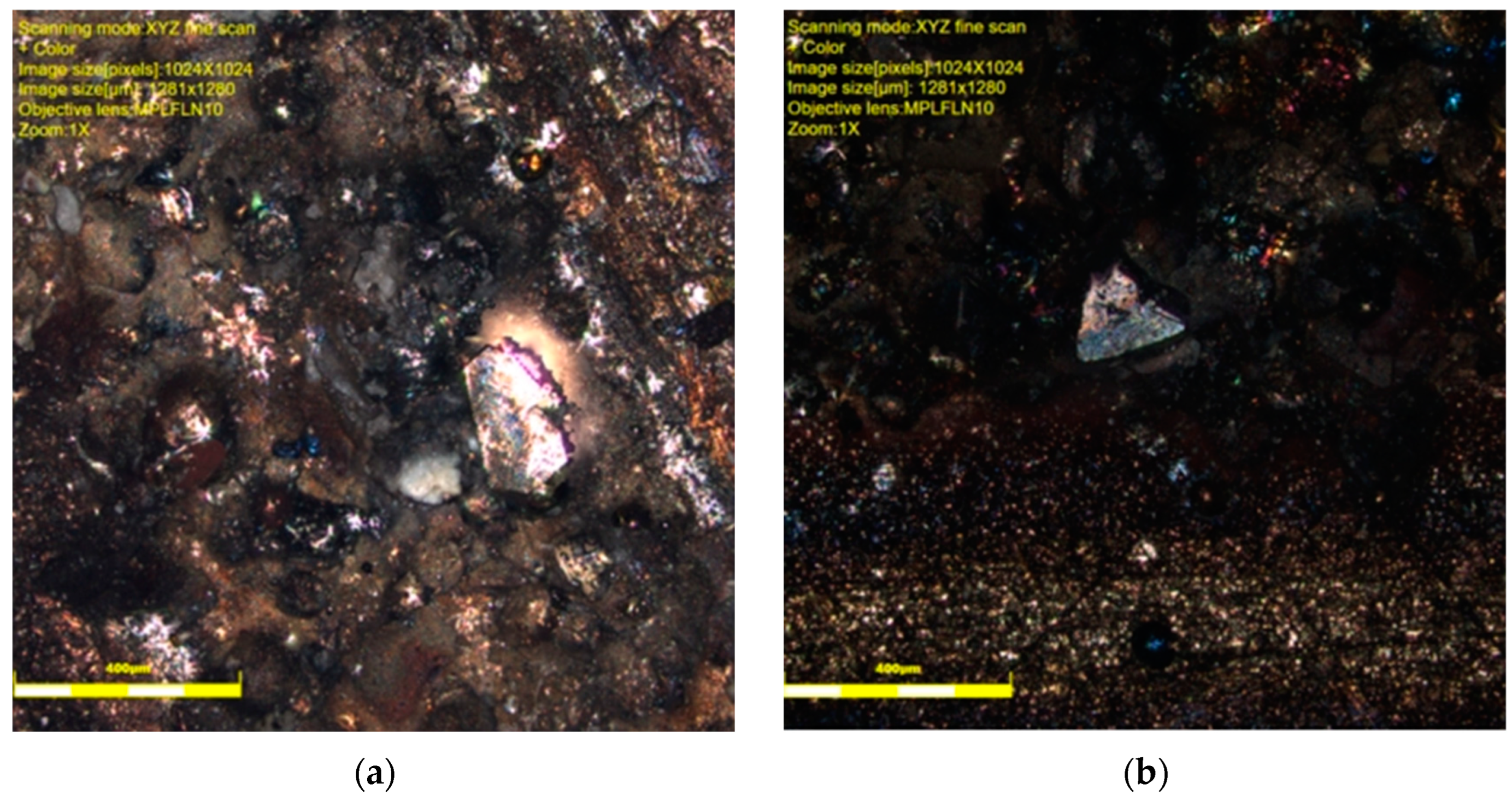
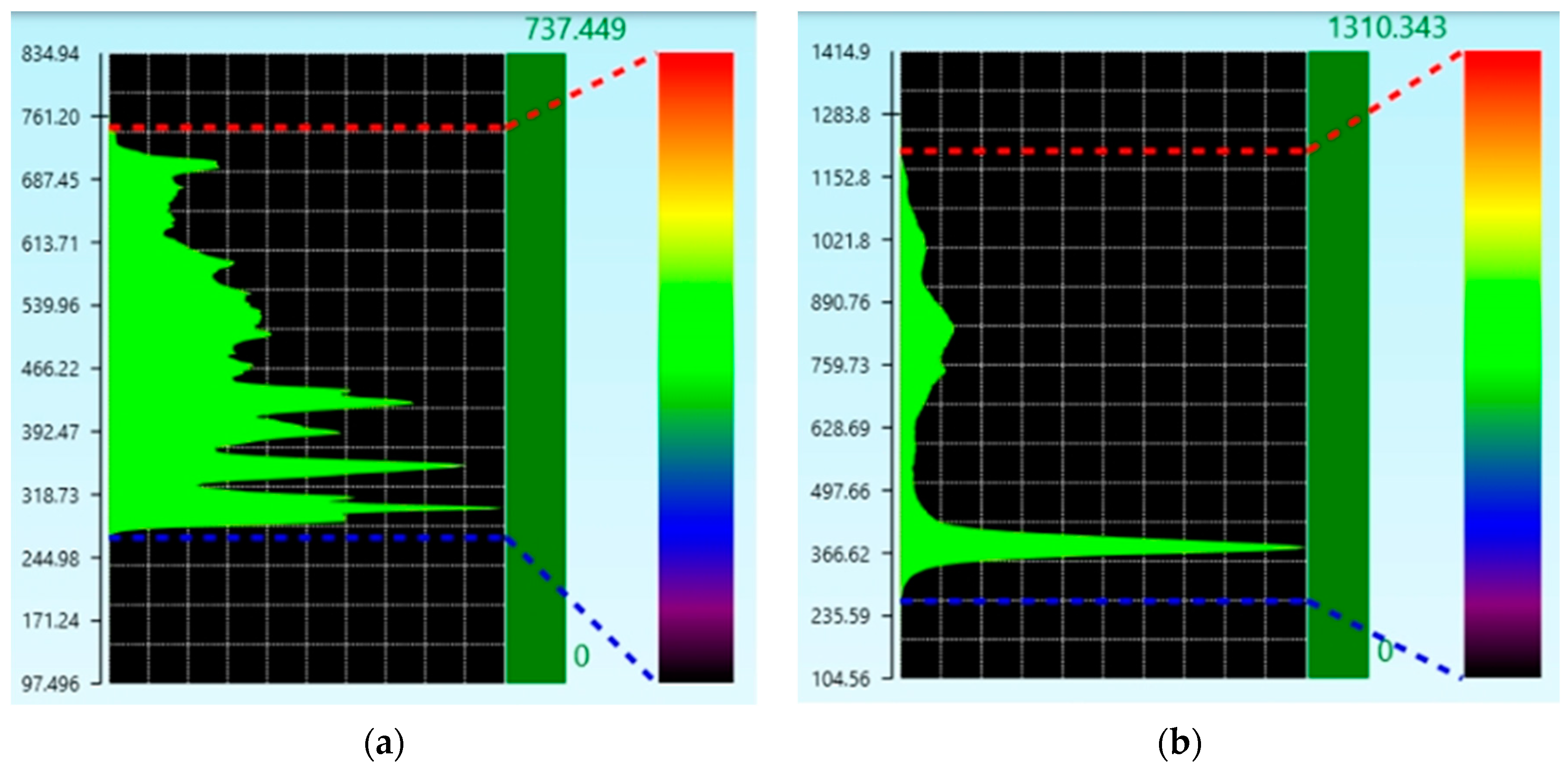
By comparing the two kinds of grinding wheel printing layers prepared with and without ultrasonic vibration, it was found that the ultrasonic effects can provide the printing layer with better surface morphology constraints. The height of each printing layer was more consistent and the CBN distribution inside the melt pool was uniform. In the case of applying ultrasonic vibration, the difference between the highest point and the lowest point of the exposed height of the CBN particles was small at about 484μm, while the size of the interval without ultrasonic vibration was 1075μm. It is proven that ultrasonic vibration can stabilize the protrusion height of CBN abrasive particles in a range. The sticky powder phenomenon on the surface of the printing layer and the grinding wheel was also improved.

Author Contributions

Conceptualization, J.L. and M.M.; methodology J.L. and M.L.; software, J.L. and M.M.; formal analysis, J.L. and M.M.; investigation, J.L., M.M. and M.L.; resources, M.M.; writing—original draft preparation, J.L.; writing—review and editing, J.L., T.Y. and J.Z.; visualization, J.L.; supervision, T.Y. and J.Z.; funding acquisition, T.Y. and M.L. All authors have read and agreed to the published version of the manuscript.

Funding

This research was funded by [the National Natural Science Foundation of China] grant number [52075088, 52305453], [the Fundamental Research Funds for the Central Universities] grant number [N2423023, N2223012], [the Natural Science Foundation of Hebei Province] grant number [E2021501027], and [Science and Technology Project of Hebei Education Department] grant number [QN2022204].

Institutional Review Board Statement

Not applicable.

Informed Consent Statement

Not applicable.

Data Availability Statement

The original contributions presented in the study are included in the article, further inquiries can be directed to the corresponding authors.

Conflicts of Interest

The authors declare no conflicts of interest.

References

  1. Zhao, J.; Chen, S.; Li, W.; Lan, Y.; Khudoley, A.; Zhang, Q.; Yao, C.; Wang, Z. Molecular dynamics simulation and experimental study of the material machinability characteristics and crack propagation mechanisms for fused silica double nanoscratches. Tribol. Int. 2024, 199, 109982. [Google Scholar] [CrossRef]
  2. Qu, S.; Sun, X.; Dong, Z.; Liu, Y.; Yang, H.; Zhang, W.; Mu, S.; Wang, Z.; Yu, T.; Zhao, J. Simulation and experimental investigation of material removal profile based on ultrasonic vibration polishing of K9 optical glass. Tribol. Int. 2024, 196, 109730. [Google Scholar] [CrossRef]
  3. Gu, Y.; Li, Z.; Lin, J.Q.; Zhou, X.Q.; Xu, Z.S.; Zhou, W.D.; Zhang, S.; Gao, Y.H. Enhanced machinability of aluminium-based silicon carbide by non-resonant vibration-assisted magnetorheological finishing. J. Mater. Process Technol. 2024, 324, 118223. [Google Scholar] [CrossRef]
  4. Zhao, J.; Xu, X.; Li, W.; Hang, W. Material removal modes and processing mechanism in microultrasonic machining of ball ceramic tool. Ceram. Int. 2024, 50, 28844–28856. [Google Scholar] [CrossRef]
  5. Stepien, P. Mechanism of grinding wheel surface reproduction in regular surface texture generation. Surf. Eng. 2008, 24, 219–225. [Google Scholar] [CrossRef]
  6. Silva, E.J.; Kirsch, B.; Bottene, A.C.; Simon, A.; Aurich, J.C.; Oliveira, J.F.G. Manufacturing of structured surfaces via grinding. J. Mater. Process Technol. 2017, 243, 170–183. [Google Scholar] [CrossRef]
  7. da Silva, E.J.; Bottene, A.C.; de Oliveira, J.F.G.; Atoatte, A.; Rodrigues, A.D. Grinding process for profiled texturing. CIRP Ann. Manuf. Technol. 2016, 65, 337–340. [Google Scholar] [CrossRef]
  8. Mao, C.; Li, X.; Zhang, M.; Zhang, J.; Zhang, W.; Luo, Y.; Tang, W.; Tang, K.; Bi, Z.; Hu, Y.; et al. Wear behaviors of electroplated CBN grinding wheel with orderly-micro-grooves in grinding narrow-deep slot. Int. J. Adv. Manuf. Technol. 2024, 131, 2857–2868. [Google Scholar] [CrossRef]
  9. Yi, J.; Yi, T.; Deng, H.; Chen, B.; Zhou, W. Theoretical modeling and experimental study on grinding force of straight groove structured grinding wheel. Int. J. Adv. Manuf. Technol. 2023, 124, 3407–3421. [Google Scholar] [CrossRef]
  10. Mao, M.; Liu, S.; Jiang, J.; Sun, S.; Wang, D. Study on flow field and convective heat transfer characteristics in grinding zone of large spiral angle flow disturbance grooved wheel. Int. J. Adv. Manuf. Technol. 2023, 129, 39–63. [Google Scholar] [CrossRef]
  11. Chen, Z.; Zhang, X.; Wen, D.; Li, S.; Wang, X.; Gan, L.; Rong, X. Improved grinding performance of SiC using an innovative bionic vein-like structured grinding wheel optimized by hydrodynamics. J. Manuf. Process 2023, 101, 195–207. [Google Scholar] [CrossRef]
  12. Yushan, L.; Guoxun, W.; Xingshan, L.; Yongchao, Q. Research on the mapping grinding of dimple surface with ordered pattern based on topological theory. Int. J. Adv. Manuf. Technol. 2022, 121, 6205–6223. [Google Scholar] [CrossRef]
  13. Monier, A.; Guo, B.; Zhao, Q.; Guo, Z.; Mahmoud, T.S.; El-mahallawi, I. The effects of structured grinding wheel designed parameters on the geometries of ground structured surfaces. Int. J. Adv. Manuf. Technol. 2022, 120, 5551–5571. [Google Scholar] [CrossRef]
  14. Zhou, F.; Xu, J.; Zhang, W.; Yu, H. Study on bottom surface quality of sapphire micro-groove grinding with structured grinding wheel. J. Hunan Univ. 2024, 51, 20–26. [Google Scholar]
  15. Fan, Z.; Lv, Y.; Li, X. The effect of force on the surface of rib grinding with ordered grinding wheel. Comb. Mach. Tools Autom. Process. Technol. 2024, 2, 151–154+159. [Google Scholar]
  16. Chen, T.; Li, Y.; Jiang, J. Theoretical model and mechanism of mirror effect of spiral grooved grinding wheel. Comb. Mach. Tools Autom. Process. Technol. 2023, 10, 43–48. [Google Scholar]
  17. Wang, W.; Li, X.; Lv, Y.; Sun, Y.; Li, X. Study on the trailing wave surface of topological grinding array with structured grinding wheel. Lubr. Seal. 2023, 48, 89–96. [Google Scholar]
  18. Zhang, D.; Lv, Y.; Li, X. Study on the grinding surface of grain grain with end grinding wheel with grain blade sequence arrangement. One Weight Tech. 2023, 3, 34–37. [Google Scholar]
  19. Wen, D.-D.; Zhang, X.-H.; Wan, L.-L.; Jiang, J.; Ding, Y.; He, T.Z.-S. Experimental study on grinding SIC ceramics with bird feather structure self-lubricating diamond wheel. Surf. Technol. 2023, 52, 91–101. [Google Scholar]
  20. Hou, Z.; Yao, Z. Grooving and Grinding Performance of Structured Wheels Fabricated with Diamond Cutting Blades. In Proceedings of the 2022 International Conference on Mechanical Engineering and Power Engineering (MEPE), Wuhan, China, 27–29 December 2022. [Google Scholar]
  21. Deng, H.; Wu, X.; Yuchi, G.; Liu, G.; Xu, Z.; Yi, J. Research on laser preparation and grinding performance of hydrophilic structured grinding wheels. Ceram. Int. 2023, 49, 7649–7661. [Google Scholar] [CrossRef]
  22. Hou, Z.; Yao, Z.; Sun, Y.; Shen, H. Grooving profile control for structured grinding wheels with picosecond pulsed laser. Int. J. Adv. Manuf. Technol. 2022, 119, 5851–5862. [Google Scholar] [CrossRef]
  23. Ma, M. Research on Ultrasonic-Assisted Laser 3D Printing Technology of Structured Grinding Wheel. Master’ Thesis, Northeastern University, Shenyang, China, 2022. [Google Scholar]
  24. Park, W.J.; Jung, H.Y.; Huh, S.C.; Yoon, H.K.; Lee, K.K. The strength and hardness of metal matrix composites by binder additives. In Advances in Fracture and Strength; Pts, 1–4, Kim, Y.J., Bae, H.D., Kim, Y.J., Eds.; Trans Tech Publications: Zurich, Switzerland, 2005; pp. 489–494. [Google Scholar]
  25. Meyer, L.; Witt, G. Investigation of the track width-dependent melt pool characteristics during laser-sintering of polyamide 12 in correlation to various focus diameters. Progress. Addit. Manuf. 2020, 5, 19–25. [Google Scholar] [CrossRef]
  26. Ji, Y.; Ren, H.; Zhao, L. Teaching consideration of wetting Angle theory for evaluating heterogeneous nucleation effectiveness. Chin. Mod. Educ. Equip. 2020, 17, 115–117+120. [Google Scholar]
  27. Chen, J.; Li, Y.; Huang, W. Study on two kinds of cracking behavior and mechanism of cladding layer in laser rapid forming process. Appl. Laser 2002, 3, 300–304. [Google Scholar]
Figure 1. The laser cladding system.
Applsci 14 07790 g001
Figure 2. Schematic diagram of the melt pool.
Applsci 14 07790 g002
Figure 3. Influence of laser power on printing layer: (a) The melt width, melt height and melt depth; (b) the shape factor and the dilution rate.
Applsci 14 07790 g003
Figure 4. Influence of sweep speed on printing layer: (a) The melt width, melt height and melt depth; (b) the shape factor and the dilution rate.
Applsci 14 07790 g004
Figure 5. Influence of the powder feeding speed on printing layer: (a) The melt width, melt height and melt depth; (b) the shape factor and the dilution rate.
Applsci 14 07790 g005
Figure 6. Influence of ultrasonic power on printing layer: (a) The melt width, melt height and melt depth; (b) the shape factor and the dilution rate.
Applsci 14 07790 g006
Figure 7. Average value diagram of the shape factor ((A): Laser Power; (B): Sweep Speed; (C): Powder Feeding Speed; (D): Ultrasonic Power Percentage).
Applsci 14 07790 g007
Figure 8. Average value diagram of the width ((A): Laser Power; (B): Sweep Speed; (C): Powder Feeding Speed; (D): Ultrasonic Power Percentage).
Applsci 14 07790 g008
Figure 9. Average value diagram of the height ((A): Laser Power; (B): Sweep Speed; (C): Powder Feeding Speed; (D): Ultrasonic Power Percentage).
Applsci 14 07790 g009
Figure 10. The surface morphology of the cladding layer (a) with ultrasonic vibration and (b) without ultrasonic vibration.
Applsci 14 07790 g010
Figure 11. CBN abrasive grain exposed interval (a) with ultrasonic vibration and (b) without ultrasonic vibration.
Applsci 14 07790 g011
Figure 12. The generation of sweep trajectory. (a) The sweep path. (b) PQArt track generation.
Applsci 14 07790 g012
Figure 13. Grinding wheel matrix.
Applsci 14 07790 g013
Figure 14. The prepared grinding wheel.
Applsci 14 07790 g014
Table 1. Experimental equipment model parameters.
Experimental InstrumentModel
Robotic armKUKA ZH30/60 Ⅲ
Shielding gasAr
Laser headRaycham RC52
Powder-feeding systemRC-PGF-1
Laser generatorIPG YLR-500
Ultrasonic system2000 bdc
Table 2. Mass fraction of elements in binder.
Elementwt%
CuBal.
Sn18.93
Ti10.37
Table 3. Laser power single-factor experiment design and results.
No.Pl
(W)
vs
(mm/s)
vr
(r/min)
Ps
(%)
B
(mm)
H
(mm)
h
(mm)
γη
120061.8100.7490.2630.0162.855.6
223561.8100.8730.3030.0182.885.6
328061.8100.9600.3480.0212.765.7
431561.8101.0520.3640.0222.895.7
535061.8101.2780.4150.0263.085.8
Table 4. Sweep speed single-factor experiment design and results.
No.Pl
(W)
vs
(mm/s)
vr
(r/min)
Ps
(%)
B
(mm)
H
(mm)
h
(mm)
γη
123531.8101.0330.5640.0351.835.8
223541.8100.9710.4600.0282.115.7
323551.8100.9530.4220.0252.265.5
423561.8100.8730.3030.0182.885.6
523571.8100.8380.2900.0162.895.2
Table 5. Powder feeding speed single-factor experiment design and results.
No.Pl
(W)
vs
(mm/s)
vr
(r/min)
Ps
(%)
B
(mm)
H
(mm)
h
(mm)
γη
123561.2100.9080.2830.0163.215.3
223561.4100.9110.2980.0173.065.4
323561.6100.9050.3150.0182.875.4
423561.8100.8730.3030.0182.885.6
523562.0100.8710.3100.0172.815.4
Table 6. Ultrasonic power single-factor experiment design and results.
No.Pl
(W)
vs
(mm/s)
vr
(r/min)
Ps
(%)
B
(mm)
H
(mm)
h
(mm)
γη
123561.800.8380.3120.0152.774.5
223561.850.8610.3040.0172.835.5
323561.8100.8730.3030.0182.885.6
423561.8150.8710.2980.0182.925.7
Table 7. Orthogonal experiment factor level.
LevelA
Laser Power Pl
(W)
B
Sweep Speed vs
(mm/s)
C
Powder Feeding Speed vr
(r/min)
D
Ultrasonic Power Percentage Ps
(%)
122051.75
223561.810
325071.915
Table 8. L9(34) orthogonal experiment table and results.
No.ABCDB (mm)H (mm)γ
122051.750.6150.5011.23
222061.9100.7130.4261.67
322071.8150.5900.2252.62
423551.9150.9770.5921.64
523561.851.4100.5432.60
623571.7100.8910.4032.21
725051.8100.9280.4811.93
825061.7150.8820.4102.15
925071.950.9080.4352.09
Table 9. Range analysis Table 1.
ItemLevelABCD
K1.7--5.59-
1.8--7.15-
1.9--5.4-
5-4.8-5.92
6-6.42--
7-6.92--
10---5.81
15---6.41
2205.52---
2356.45---
2506.17---
K avg1.7--1.86-
1.8--2.38-
1.9--1.8-
5-1.6-1.97
6-2.14--
7-2.31--
10---1.94
15---2.14
2201.84---
2352.15---
2502.06---
Optimum level23571.815
R0.310.710.580.2
Level quantity3333
Number of repetitions per level r3333
Table 10. Range analysis Table 2.
ItemLevelABCD
K0.05---2.93
0.1---2.53
0.15---2.45
1.7--2.39-
1.8--2.93-
1.9--2.6-
5-2.52--
6-3--
7-2.39--
2201.92---
2353.28---
2502.72---
K avg0.05---0.98
0.1---0.84
0.15---0.82
1.7--0.8-
1.8--0.98-
1.9--0.87-
5-0.84--
6-1--
7-0.8--
2200.64---
2351.09---
2500.91---
Optimum level23561.80.05
R0.450.210.180.16
Level quantity3333
Number of repetitions per level r3333
Table 11. Range analysis Table 3.
ItemLevelABCD
K0.05---1.48
0.1---1.31
0.15---1.23
1.7--1.31-
1.8--1.25-
1.9--1.45-
5-1.57--
6-1.38--
7-1.06--
2201.15---
2351.54---
2501.33---
K avg0.05---0.49
0.1---0.44
0.15---0.41
1.7--0.44-
1.8--0.42-
1.9--0.48-
5-0.52--
6-0.46--
7-0.35--
2200.38---
2350.51---
2500.44---
Optimum level23551.90.05
R0.130.170.070.08
Level quantity3333
Number of repetitions per level r3333
Table 12. Variance analysis table for shape factor.
Difference SourceSum of SquaresdfMean SquareFp
Intercept36.562136.562481.8560.002 **
B0.81920.4095.3950.156
C0.61520.3074.0510.198
D0.06820.0340.4480.69
Residual0.15220.076
R2: 0.908; * p < 0.05, ** p < 0.01.
Table 13. Variance analysis table for width.
Difference SourceSum of SquaresdfMean SquareFp
Intercept6.95916.95944.6860.022 *
B0.0720.0350.2250.816
C0.04920.0250.1590.863
D0.04520.0220.1430.875
Residual0.31120.156
R2: 0.345; * p < 0.05, ** p < 0.01.
Table 14. Variance analysis table for height.
Difference SourceSum of SquaresdfMean SquareFp
Intercept1.79211.792143.8640.007 **
B0.04420.0221.780.36
C0.00720.0040.2910.775
D0.01120.0050.4410.694
Residual0.02520.012
R2: 0.715, * p < 0.05 ** p < 0.01.
Disclaimer/Publisher’s Note: The statements, opinions and data contained in all publications are solely those of the individual author(s) and contributor(s) and not of MDPI and/or the editor(s). MDPI and/or the editor(s) disclaim responsibility for any injury to people or property resulting from any ideas, methods, instructions or products referred to in the content.

