Review

Advancements in Key Parameters of Frequency-Modulated Continuous-Wave Light Detection and Ranging: A Research Review

1
Key Laboratory of Luminescence Science and Technology, Chinese Academy of Sciences & State Key Laboratory of Luminescence Science and Applications, Changchun Institute of Optics, Fine Mechanics and Physics, Chinese Academy of Sciences, Changchun 130033, China
2
University of Chinese Academy of Sciences, Beijing 100049, China
3
Jlight Semiconductor Technology Co., Ltd., Changchun 130033, China
*
Authors to whom correspondence should be addressed.
Appl. Sci. 2024, 14(17), 7810; https://doi.org/10.3390/app14177810
Submission received: 24 July 2024 / Revised: 30 August 2024 / Accepted: 2 September 2024 / Published: 3 September 2024
(This article belongs to the Special Issue Optical Sensors: Applications, Performance and Challenges)

Abstract

:
As LiDAR technology progressively advances, the capability of radar in detecting targets has become increasingly vital across diverse domains, including industrial, military, and automotive sectors. Frequency-modulated continuous-wave (FMCW) LiDAR in particular has garnered substantial interest due to its efficient direct velocity measurement and excellent anti-interference characteristics. It is widely recognized for its significant potential within radar technology. This study begins by elucidating the operational mechanism of FMCW LiDAR and delves into its basic principles. It discuss, in depth, the influence of various parameters on FMCW LiDAR’s performance and reviews the latest progress in the field. This paper proposes that future studies should focus on the synergistic optimization of key parameters to promote the miniaturization, weight reduction, cost-effectiveness, and longevity of FMCW LiDAR systems. This approach aims at the comprehensive development of FMCW LiDAR, striving for significant improvements in system performance. By optimizing these key parameters, the goal is to promote FMCW LiDAR technology, ensuring more reliable and accurate applications in automated driving and environmental sensing.

1. Introduction

LiDAR is an active remote-sensing technology that uses lasers for imaging, reconnaissance, and ranging. It boasts advantages such as high-resolution, precision, portability, and high immunity to interference and finds widespread use in meteorology, laser-induced processes, and intelligent driving [1].
Currently, LiDAR detection technology is bifurcated into two main types: incoherent and coherent. Incoherent detection, or direct detection, involves the direct measurement of the intensity variation of the reflected light signal. This straightforward and efficient method is prevalent in time-of-flight (TOF) l LiDAR systems.
Conversely, coherent detection technology uses heterodyne detection methods, comparing the frequency or phase difference between the echo and local oscillator signals for detection. Frequency-modulated continuous-wave (FMCW) LiDAR represents the forefront of this technology [2].
TOF LiDAR is often favored for its high accuracy, rapid response, and broad applicability. However, its performance may be limited within complex environments. FMCW LiDAR, however, has demonstrated significant advantages, positioning it as an advanced detection technology. Its primary benefit lies in the use of coherent detection technology, which eliminates the need for expensive single-photon detection devices and the generation of high peak power pulses. Additionally, FMCW LiDAR exhibits a high resistance to various interferences, including background illumination and ground scattering. When detecting dynamic targets, FMCW LiDAR leverages the optical Doppler frequency shift in received light signals, using the Doppler effect to instantly measure the target’s velocity. This technology achieves high-resolution distance measurements while simultaneously acquiring distance and velocity information of the target in a single measurement process. The interference resistance of FMCW LiDAR denotes its capability to negate the effects of other light sources, enhancing its reliability in complex environments. With significant advantages in accurate velocity and position measurement, as well as noise suppression from light and environmental factors, FMCW LiDAR is particularly suitable for scenarios requiring target velocity information. Table 1 summarizes the advantages and disadvantages of both detection methods [3], highlighting the widespread research interest in FMCW LiDAR due to its numerous advantages.
This paper focuses on FMCW LiDAR, emphasizing its fundamental principles. It subsequently explores the impact of several key parameters on FMCW LiDAR performance and summarizes recent research advances in the field. Future research should aim to optimize these critical parameters collaboratively to enhance the miniaturization, portability, cost-effectiveness, and longevity of FMCW LiDAR systems. This endeavor seeks to improve the performance of FMCW LiDAR systems comprehensively, providing more reliable and precise solutions for applications in autonomous driving and environmental sensing.

2. FMCW LiDAR

FMCW LiDAR represents an advanced ranging technology that excels in precisely measuring distances to targets. Esteemed for its broad measurement range and superior accuracy, FMCW LiDAR enables non-contact measurements, distinguishing itself as a versatile tool. A primary advantage of FMCW LiDAR lies in its capacity to ascertain velocity information. In FMCW operation, the LiDAR emits a frequency-modulated continuous laser, which is split into two beams. One beam is directed toward the target, while the other serves as a reference signal or local oscillator, directed to the photodiode (PD) [4]. The sampled signal is compared with a reference signal in the frequency domain, and the distance and velocity of the target object are then calculated using the Doppler effect. Given its distinctive capabilities, FMCW LiDAR has emerged as an important area of interest within the field of LiDAR technology.

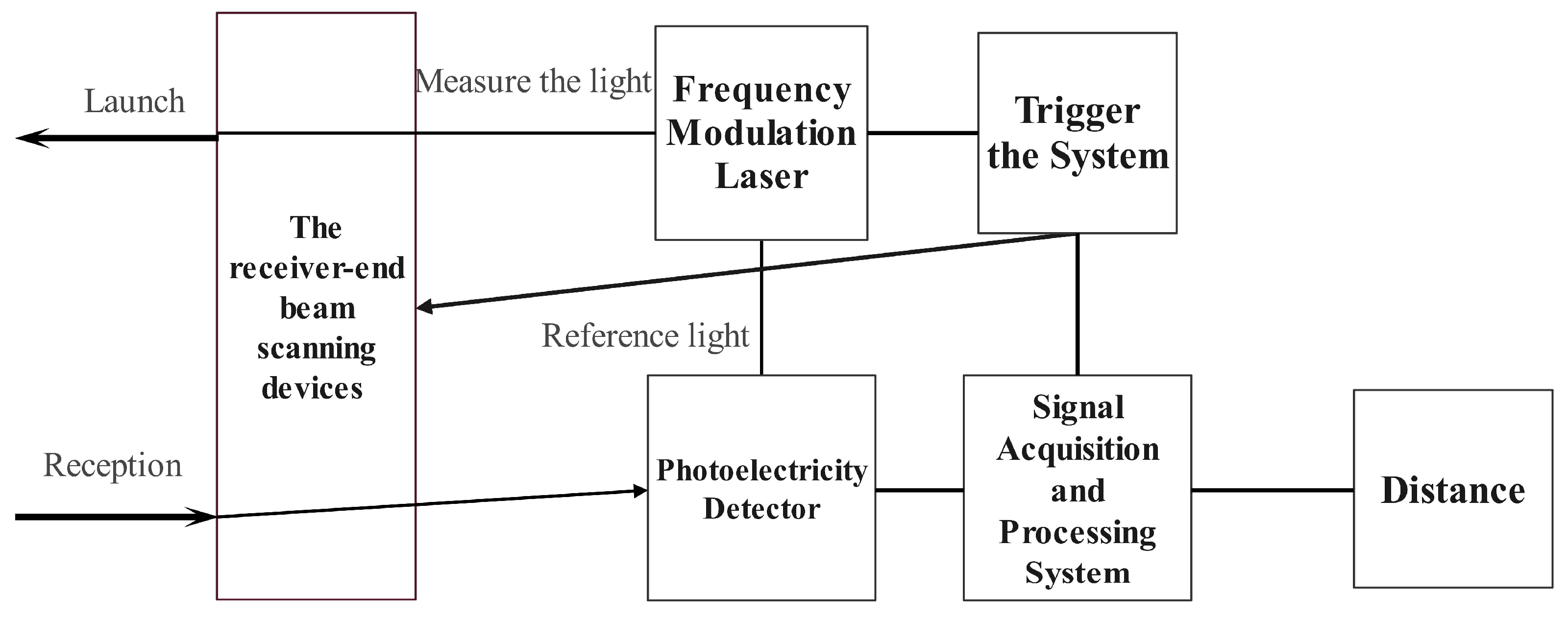
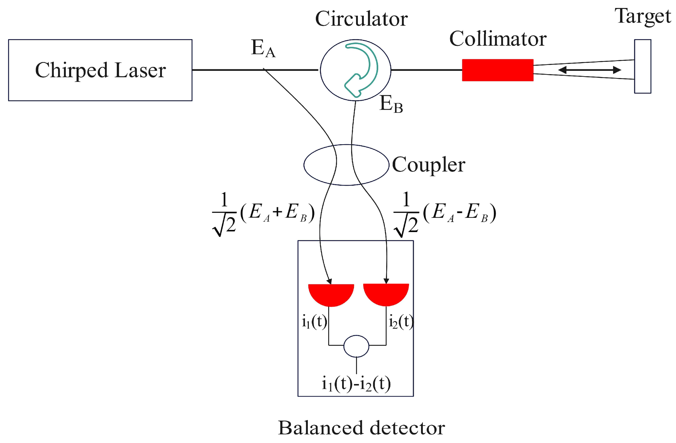
2.1. FMCW LiDAR System Architecture

The FMCW LiDAR operates as an advanced radar system, emitting light waves of constant, significant power that vary in temporal frequency or phase during cyclic changes. This system uses coherent detection technology to perform measurements by analyzing differences between echo and transmitted signals, demonstrating a high degree of precision.
In FMCW LiDAR systems, the core components include the trigger system module, the signal acquisition and processing system module, the receiver-end beam scanning system, the frequency-modulated laser, and the photodetector, as depicted in Figure 1. Upon receiving a command to start measurement, the trigger module initiates and simultaneously activates the frequency-modulated laser module, the receiver-end beam scanning system, and the signal acquisition and processing module. In the single-point measurement mode, the receiver-end beam scanning system may remain stationary, typically used for precise measurements of fixed targets, hence focusing on a fixed point without the need for dynamic scanning. However, in dynamic measurement modes, scanning across multiple targets or entire target areas is required; thus, the receiver-end beam scanning system operates synchronously, dynamically adjusting the direction of received beams to continuously scan points in space, relaying data to the computer for processing in real-time. The frequency-modulated laser module, under the control of the trigger signal, produces a laser frequency modulated by triangular or sawtooth waves. Ninety-nine percent of the laser is transmitted through an optical fiber path into free space for measurement, while one percent is directly transmitted to the photodetector for interference with the reflected measurement light. The signal acquisition and processing module starts synchronously, processing the interference signals from the photodetector.
The trigger module is composed of both software and hardware triggering elements. In continuous measurement mode, this module is tasked with delivering software-generated instructions to the laser. As the laser emits a linearly frequency-modulated beam, it concurrently sends synchronization signals to the acquisition card and the receiver-end beam scanning system. Upon receiving the beat frequency signals and data from the receiver’s beam scanning device, the system processes this information collectively to estimate the target’s characteristics. The synchronization of the triggering is vital for the accuracy of measurements. Imprecise synchronization may lead to inconsistent data, thereby impacting the final measurement results.
The receiver-end beam scanning devices of FMCW LiDAR systems can take various forms in different designs, each with its specific advantages and application scenarios. The main types include one-dimensional and two-dimensional steering mirrors, which can be precisely controlled through mechanical or motor mechanisms to adjust the beam’s direction, suitable for applications requiring rapid and precise angular adjustments; micro-electromechanical systems (MEMS) scanning mirrors utilize miniature motors to drive small mirrors for fast and accurate beam scanning, ideal for portable or miniaturized LiDAR systems where space and weight are critical considerations; optical phased array (OPA) chips are key hardware components for implementing OPA technology, using electronically controlled optical phase modulators to change the beam’s propagation direction without mechanical movement, offering extremely high scanning speed and flexibility; reflective mirror systems use directional mirrors to optimize optical path design, ensuring laser transmission to the target area; and three-dimensional rotation platforms typically include two motors, controlling rotation in horizontal and vertical directions, capable of dynamic scanning in multiple directions, thus providing a comprehensive view and high-precision angular resolution. The selection of these scanning technologies in FMCW LiDAR systems depends on specific application requirements, such as scanning speed, precision, system size, and cost, to achieve efficient and precise target detection and distance measurement [5].
The signal acquisition and processing unit comprises a high-speed acquisition card, a computer, and measurement software. This unit collects the photonic signals after beat frequency via the high-speed acquisition card, where the signals undergo preprocessing such as amplification and filtering to enhance signal quality. Initially, the signals pass through a broadband, low-noise filter, followed by a low-pass filter to reduce noise and interference, thereby improving the signal-to-noise ratio. After filtering, the signals are amplified by a variable gain amplifier (VGA) and undergo analog-to-digital conversion (A/D). The digital signals are further processed in the measurement software, including digital filtering to select the required frequency bands and extract useful spectral components. Subsequently, fast Fourier transform and spectral subdivision are performed to extract signal frequency values, thus estimating target characteristics. Depending on the specific configuration of the system and application requirements, these data can be further processed to determine the spatial location of the target or other relevant characteristics.

2.2. FMCW LiDAR Principle of Operation

Figure 2 shows the basic ranging principle diagram of FMCW LiDAR. FMCW LiDAR uses a modulated continuous laser signal to measure the distance and speed of the target by mixing the transmitted light and the received light. The system uses a linear frequency modulated chirped laser as the transmission signal and the local oscillator signal to mix the weak scattered signal with the strong local oscillator signal on the detector. The signal is significantly amplified by this mixing process, allowing relatively noisy detectors to be used. Due to the use of coherent detection, FMCW LiDAR can directly measure the velocity of moving objects by sensing the Doppler shift of light, and because the detector can only detect light close to the frequency of the local oscillator light, it is almost unaffected by interference from ambient light. Although more sophisticated implementations may replace the balanced detector with a full coherent receiver and introduce additional components to sample multiple polarizations, this does not have a major influence on the basic physics of operation.
The system combines the light from the two input A and B on a coupler and then detects it by two photodiodes. The photocurrent difference i ( t ) between the two photodiodes is used as the output of the receiver; the system can obtain the frequency difference through the photocurrent difference, thereby measuring the distance and speed of the target. The electric field E 1 of the first photodiode and the corresponding photocurrent i 1 t are
E 1 = 1 2 E A + E B = 1 2 A cos ω A t + B cos ω B t , i 1 t = 1 2 i A + i B + i A i B cos ω A ω B t ,
where E 1 represents the electric field of the first photodiode, i 1 t is the photocurrent of the first photodiode, E A and E B represent different input light fields, A and B are the amplitude of E A and the amplitude of E B , i A and i B represent different input time-averaged photocurrents, and ω A and ω B represent different light frequencies.
The second photodiode electric field E 2 and the corresponding photocurrent i 2 t are
E 2 = 1 2 E A E B = 1 2 A cos ω A t B cos ω B t , i 2 t = 1 2 i A + i B i A i B cos ω A ω B t ,
where E 2 represents the electric field of the second photodiode, i 2 t is the photocurrent of the second photodiode, E A and E B represent different input light fields, A and B are the amplitude of E A and the amplitude of E B , i A and i B represent different input time-averaged photocurrents, and ω A and ω B represent different light frequencies.
The output current i ( t ) is the difference between the first photodiode photocurrent i 1 t and the second photodiode laser photocurrent i 2 t :
i t = i 1 t i 2 t = 2 i A i B cos ω A ω B t   ,
where i 1 t is the photocurrent of the first photodiode, i 2 t is the photocurrent of the second photodiode, i A and i B represent different input time-averaged photocurrents, and ω A and ω B represent different optical frequencies. Therefore, the optical heterodyne detector directly measures the frequency difference ω A ω B between the two input beams, and the FMCW LiDAR directly uses this to measure the target distance, which we will discuss in Section 2.3.1.
The basic working principle of FMCW LiDAR is to emit a laser beam with linear frequency modulation and receive the light signal reflected by the target. The frequency of the emitted light changes linearly over time to form a frequency modulated signal. The received reflected signal is mixed with the emitted signal, and the frequency difference can be used to measure the distance of the target, while the Doppler shift in the signal can be used to measure the speed of the target.
In the case of a static target, the signal received by the FMCW LiDAR system is simply a time-delayed version of the transmitted signal. By mixing the transmitted and received signals on an optical heterodyne receiver, the frequency difference between the transmitted and received signal can be extracted. The frequency difference is proportional to the round-trip time:
R = c · τ 2 ,
where R is the target distance, c is the speed of light, and τ is the time delay.
When the target object is moving, the received signal will have an additional frequency shift, f D , due to the Doppler effect. This frequency shift is proportional to the speed v of the target object:
f D 2 v λ   ,
where λ represents the wavelength, f D represents the additional frequency shift due to the Doppler effect, and v is the velocity of the target object
The performance of FMCW LiDAR is also affected by the modulation waveform. The modulation waveform frequency used varies depending on the measurement purpose [6]. Commonly used waveforms include triangle wave and sawtooth wave.

2.2.1. Triangular FMCW

The operational mechanism of triangular FMCW LiDAR unfolds in a three-step sequence. Initially, the frequency of the transmitted signal linearly varies up and down periodically with time, the rise time is equal to the fall time, and the average value of the frequency is f C . The transmission delay from the collimator to the target and then scattering back to the receiver is τ , and the range of the signal frequency is the bandwidth B . The frequency difference consists of the amount of frequency change f R and the Doppler shift f D introduced by the propagation delay τ , and the frequency difference Δ f 1 and Δ f 2 between f R and f D can be obtained by coherent demodulation of each of them. The frequency difference Δ f 1 and the frequency difference Δ f 2 generated at the rising and falling edges of the frequency each differ by f D from f R . Subsequently, the frequency difference f R and the Doppler shift f D introduced by the distance can be calculated using Δ f 1 and Δ f 2 through coherent demodulation, as illustrated in Figure 3. The formula for calculating the frequency difference is as follows [7]:
f R = f 1 + f 2 2 f D = f 1 f 2 2 γ = 2 B T τ = f R γ = f 1 + f 2 T 4 B     v = f D · c f c = f 1 f 2 · c 2 · f c R = c · τ 2 = f 1 + f 2 · c 4 γ .
This formula defines f 1   as the frequency difference generated on the rising edge of the frequency, f 2 as frequency difference generated on the falling edge of the frequency, v as the target the velocity projection on the line between LiDAR and the measured target, R as the distance between the FMCW LiDAR and the target object, c as the speed of light, and f c as the central frequency of the optical wave in the transmitted signal. f D represents the Doppler shift. The symbol τ is used to denote the time taken for the collimator to emit radiation toward the target object and then scatter back to the receiver. f R represents the amount of frequency change, while γ denotes the rate of frequency change of the signal. B represents the range of frequency change of the signal, i.e., the bandwidth, which is generally 3 GHz, and T denotes the period of a chirp, which is generally 10 μs to 50 μs.

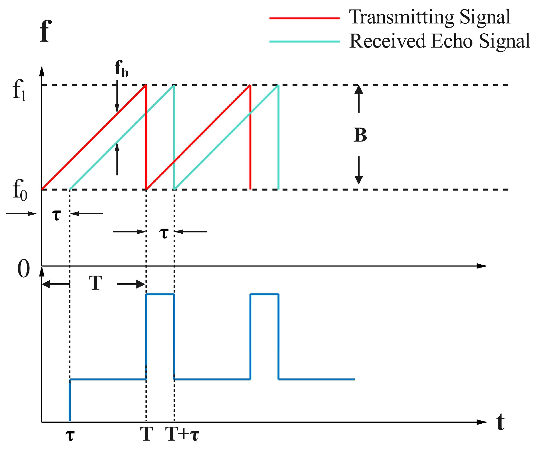
2.2.2. Sawtooth-Shaped FMCW

Sawtooth FMCW technology facilitates the determination of both distance of a target through the noncoherent accumulation of signals over multiple periods. This technique generates a two-dimensional dataset, subsequently analyzed via a two-dimensional FFT to obtain detailed information on the target’s distance, as shown in Figure 4. The figure illustrates the variation of the laser optical frequency over time after modulation. B represents the modulation range of the laser, denoted as f 0 , f 1 . The two sawtooth waves correspond to the optical frequencies of the two light beams, where the solid and dashed lines represent fixed frequency values at a given moment. Due to a time delay τ between the two light beams, a frequency difference is observed upon reception. The employed formula is structured as follows [8]:
R = O P D 2 n = T · c 2 n B · f b .
The formula includes various variables: f b represents the absolute value of the frequency difference between the signal light and the local oscillator light; it contains crucial information regarding the distance to the target. Optical path difference ( O P D ) stands for the optical path difference between two coherent beams. B signifies the laser’s frequency-modulation range (the bandwidth). T represents the modulation period. c refers to the speed of light. n indicates the refractive index. R is the distance to the detection target.

2.3. FMCW LiDAR Key Parameters

With the continuous advancement of LiDAR technology, FMCW LiDAR has demonstrated exceptional performance in various aspects. Its advantages in interference resistance, long-distance measurement capability, and high resolution can be attributed to the meticulous design and fulfillment of its key performance metrics.
FMCW LiDAR stands out for its exceptional anti-interference performance, reliably resisting external disturbances and ensuring consistent performance in complex environments. Through strategic modulation signal frequency range selection and system parameter optimization, the system guarantees precise distance measurements, even for remote targets. By focusing on key performance indicators such as frequency modulation range, FMCW LiDAR achieves significant resolution, substantially improving target recognition and localization. This enables the system to acquire finer spatial information during measurements, thereby enhancing the accuracy of target recognition and localization. These characteristics allow FMCW LiDAR to better handle complex scenarios such as electromagnetic interference and ambient light disturbances in practical applications, providing a reliable foundation for precise measurements.
This study delves into several pivotal performance indicators of the FMCW LiDAR system, evaluating their significance in system evaluation and their direct impact on its operational efficiency.

2.3.1. Detection Distance and Accuracy

Detection range stands as a crucial parameter for evaluating LiDAR system’s performance. Figure 5 shows the FMCW ranging method. First, the transmitter sends out a set of frequency ft that linearly varies with the time laser signal. The modulation bandwidth for B and modulation time for t s will be adjusted after the laser beam beams for the local oscillation beam and the detection of the beam. Then, the detection of the beam after experiencing a detection distance of d after the echo beam produced by the detection system to receive—due to the existence of flight delay t E —the received echo beam frequency f r and the frequency of the local oscillation beam f t differ with the frequency of the beam fb, as shown in the image below [9].
f b = 2 · R · B c · t s
The equation governing this process incorporates several variables: c is the speed of light; t s is modulation time; R is the detection distance; f b is the frequency difference between the echobeam and the local oscillation beam at the same moment; and B signifies the laser’s frequency-modulation range.
Due to the limitations of the detector devices, the high-frequency component cannot be detected, so the light intensity expression for the received mixed frequency beam:
I t = A · B cos ω A t ω B t t + φ A φ B = A · B cos 2 π f b t + φ A φ B .
In the equation, I t is the light intensity of a mixed-frequency beam; A and B are the electric field amplitudes of the local oscillator beam and the probe beam; ω A t and ω B t are the electric field frequencies that change linearly with time; and φ A and φ B are the electric field phases of the local oscillator beam and the probe beam. The frequency of the resulting mixing signal is the desired frequency difference f b , which can be combined with Equation (8) to find the detection distance R .
In FMCW LiDAR, the maximum detection range is a crucial indicator influenced by several factors. This range is determined by the repetition period of the transmitted signal, where only return signals received within this period or sooner can be accurately interpreted as distance information. Returns arriving after this period risk being misinterpreted as signals from subsequent signals, creating potential ambiguity [10].
Moreover, the maximum detection range is contingent on the coherence length of the optical wave signal. When the target’s echo exceeds this length, beat frequency signal might significantly diminish, resulting in a lower signal-to-noise ratio (SNR) and preventing effective detection. The SNR is further influenced by the transmitted light power, receiver’s bandwidth and sensitivity, and the level of environmental noise.
Notably, FMCW LiDAR has the advantages of high precision and large data volume compared with microwave radar; however, the detection ability of FMCW LiDAR is affected by the atmospheric environment (including very large rain, snow, haze, and other factors). The impact of atmospheric transmission on LIDAR is primarily reflected in the atmospheric absorption, atmospheric scattering, and atmospheric turbulence. When the FMCW LiDAR is utilized in medium- and short-range detection, the impact of atmospheric turbulence is less than that of atmospheric absorption and atmospheric scattering.
As FMCW LiDAR technology advances, its application scope broadens, promoting an escalation in performance requirements. Current research efforts aim to improve detection accuracy and performance through such as balanced detectors, PIN photodiode (PIN-PD), and optical phased array (OPA) to satisfy the growing need for high-performance detection systems. OPA technology represents a significant research avenue within this domain, offering substantial benefits for improving the integration of radar systems.
OPA technology, which precisely controls the phase of light beams to create a main beam with specified directivity for accurate scanning [11]. The optical beams emitted by each waveguide or antenna can be considered as slits propagating through the air and interfering with each other. According to the multi-slit Fraunhofer diffraction model, these interfering beams will be reinforced in certain directions while being attenuated in others, thus enabling beam steering. By controlling the phase differences between each beam, it is possible to direct the enhanced interference beams and achieve beam scanning. Optical phased arrays can be classified into one-dimensional and two-dimensional scanning systems based on the dimension of the scanned output beam. One-dimensional scanning in optical phased arrays can be directly realized by modulating the phase difference of the beams. Two-dimensional scanning, on the other hand, is typically achieved using one of two methods: one involves etching a grating on the waveguide and utilizing the diffraction characteristics of the grating, where altering the wavelength of the laser can control the direction in the second dimension; the other method uses a two-dimensional emitter array to achieve two-dimensional beam scanning.
The primary materials used in the fabrication of optical phased arrays (OPA) include lithium niobate, liquid crystals, ceramics, and silicon-based materials. Currently, with the rapid advancement of silicon photonics technology, it has become feasible to fabricate optical phased array chips using silicon-on-insulator (SOI) technology. Compared to traditional mechanical radar systems, OPA chips achieve fully solid-state beam scanning and control using electrical signals, eliminating the need for mechanical movement and thereby significantly enhancing radar reliability and lifespan. Additionally, OPA chips manufactured using complementary metal oxide semiconductor (CMOS) technology are compact, cost-effective, and have low drive power consumption. These chips can also be integrated with laser and detector chips, making them an optimal choice for developing solid-state, low-cost, and automotive-grade LiDAR systems. Furthermore, advancements in OPA technology open new possibilities for the integration of FMCW LiDAR systems, including combined integration with laser emitters and detector chips. This represents a new trend in the development of low-cost, high-performance FMCW LiDAR technology. Due to their substantial benefits in size reduction and cost efficiency, OPA technology is considered one of the most promising directions in LiDAR technology development.
The array scale of OPA has continually expanded, advancing from 128 channels to as many as 9216 channels. Despite the high complexity in driving and controlling large-scale OPA arrays, there are now dense electronic driving circuits and sophisticated algorithms available to coordinate the elements within these arrays. Additionally, the scanning field of view of OPA is progressively broadening, and the level of sidelobe suppression is also being enhanced. Some entities have developed complete chip packaging, high-speed driving circuits, and advanced high-throughput signal processing techniques, successfully achieving high-quality FMCW point cloud outputs [12].
In 2023, the WATTS MR team at the Massachusetts Institute of Technology proposed an on-chip FMCW LiDAR system based on a 9216-channel OPA chip. The inter-element spacing within the OPA chip is 1.7 μm, with an aperture size of 94 mm2, and a scanning field of view of 50° × 11°. The system achieved coherent detection of targets beyond 50 m, with an average power of 125 μW per driving unit, a resolution time of less than 3.8 μs, and a capability of producing 10,000 point clouds per second [13].
Although the operating principles of silicon-based OPA are relatively mature, optimizing power consumption costs and device structures remains a crucial consideration in designing silicon-based solid-state FMCW LiDAR systems for long-range, high-resolution detection. Currently, the detection range and accuracy are relatively limited, which does not yet meet the needs for long-range, high-precision detection. In the short term, such technology may find applications in areas like vehicular LiDAR. Future research directions include the continuous improvement and high-level integration of high-power semiconductor lasers, low-loss passive optical transmission devices, high-performance on-chip OPA architectures, and balanced receiver arrays. If the issue of losses can be addressed, this technology could be further applied in long-range, high-precision target detection.

2.3.2. Distance Resolution and Ranging Accuracy

The distance resolution of the FMCW LiDAR system, indicative of the minimum distinguishable separation between targets within a single measurement. The distance resolution is primarily influenced by the modulation bandwidth B of the light source, and the distance resolution must satisfy the following criterion [14]:
S r = c 2 · n · B .
The equation shows a negative correlation between distance resolution S r and the modulation range B of the light source, with c denoting wavelength and n the refractive index. Expanding the modulation bandwidth B of the light source leads to a reduction of the distance resolution S r ; i.e., the distance resolution becomes smaller, and the accuracy of the system increases. Therefore, expanding the modulation range of the light source emerges as a viable strategy for enhancing the ranging resolution of the LiDAR. In FMCW LiDAR, the distance resolution is mainly influenced by the light source’s performance parameters, making the generation of high-quality frequency-modulated optical signals a key area of research focus within the scientific community [15].
The distance resolution and SNR will jointly affect the ranging accuracy of FMCW LiDAR; the accuracy of the LiDAR’s range measurements is intricately related to the SNR. When the SNR exceeds a certain threshold, the ranging data distribution aligns with a normal distribution, ensuring high accuracy. However, a decline in SNR broadens the data distribution range, consequently diminishing the ranging accuracy.
In addition, the period of the FMCW LiDAR also indirectly affects the ranging accuracy. The period mainly affects the speed and density of point cloud generation, but it also affects the ranging accuracy of the system. A shorter period usually increases the sampling frequency, which, in turn, increases the point cloud density, providing more-accurate distance measurements in real-time processing. However, a period that is too short may introduce nonlinear errors, which may have a negative impact on ranging accuracy. These errors usually come from inaccurate frequency modulation or problems with the dynamic response of the system. Therefore, finding a suitable period to balance the sampling rate and error is the key.

2.3.3. Angular Resolution

The angular resolution of FMCW LiDAR refers to the ability of the LiDAR to discriminate targets at the same distance R but at different relative angles in a single measurement [16]. According to the Rayleigh criterion of a Gaussian beam, the beam divergence angle θ is affected by the aperture d of the collimator at the transmitter end and the wavelength λ of the optical carrier wave, which satisfies θ = 1.27 λ d . The distinguishable radial distance S A can be expressed as follows when the measurement distance is R :
S A 2 R · sin θ 2 .
In the equation, S A is the radial distance angular resolution, R is the measurement distance, and θ indicates the beam divergence angle. With a fixed operating wavelength, common methods to improve angular resolution include increasing the optical apertured of the receiving system or reducing the beam divergence angle θ . The angular resolution of FMCW LiDAR depends not only on the characteristics of the light source but also on the optical design of the receiving system. In the receiving system, the beam divergence angle θ is constrained by the aperture d . A larger aperture helps to reduce the beam divergence angle, thereby enhancing the angular resolution. Therefore, FMCW LiDAR used for imaging is often combined with synthetic aperture techniques. By conducting multiple measurements of a target at different positions and applying correlation algorithms, the virtual aperture is enlarged to improve angular resolution [17].

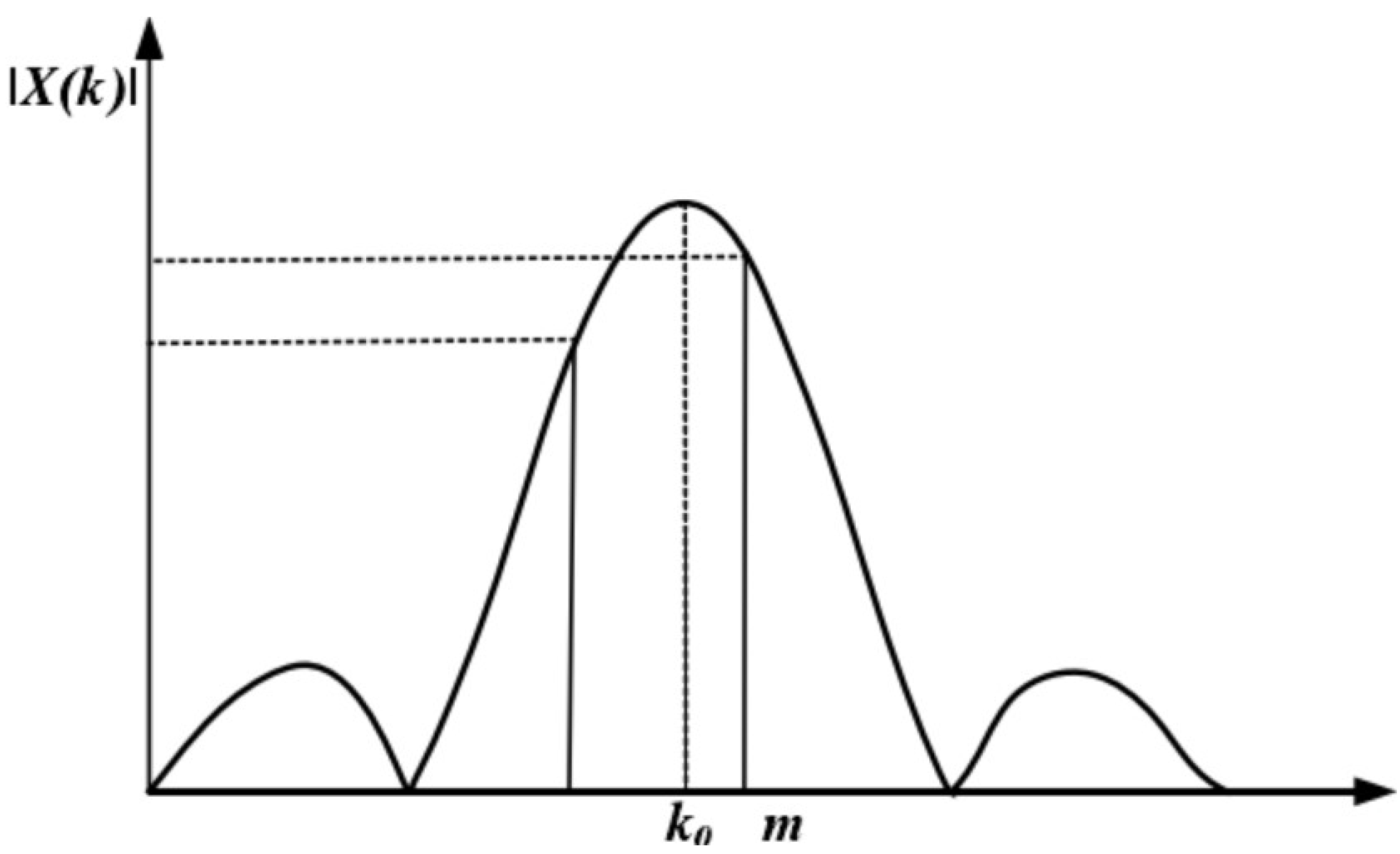
2.3.4. Random Noise and Signal Processing

In practice, FMCW LiDAR is subjected to various types of interference, and random noise is also an important influencing factor that leads to a decrease in range accuracy. Since the laser transmission loses a large amount of optical energy in the atmosphere, the received echo signal has a very low signal-to-noise ratio and is susceptible to noise interference. The main noise in the ranging process is generated by the internal components of the system, as well as noise entering the system through the receiver, including time-domain waveform continuity, amplitude, and phase of random noise, belonging to the Gaussian noise. The power spectral density distribution of these noises is again a constant value; thus, the noise in the differential frequency signal can be treated as Gaussian white noise.
Figure 6 illustrates the actual signal waveform detected by the FMCW LiDAR. The detected echo signal in the figure contains a sinusoidal signal; however, the superposition of random noise leads to varying degrees of distortion in the amplitude and phase of the waveform, thereby reducing the signal-to-noise ratio of the signal. Excessive noise power can lead to incorrect estimation of spectral peaks in spectral analysis, resulting in a reduction in range accuracy. Therefore, denoising the signals in the processing of the acquired signals is necessary to ensure that the frequency values of the differential frequency signals can be correctly extracted.
Due to the advantages of digital signal processing, the fast Fourier transform (FFT) spectral analysis method is often employed to process the beat frequency signals. Following discrete processing, the expression for the sequence of the beat frequency signal is obtained as follows [18]:
x n = A cos ω 0 n + φ 0 , n 0 , N 1 ω 0 = 2 π · f 0 f s , ω 0 ϵ 0,2 π .
In the equation, x n represents the discretely processed beat frequency signal, and N is the sampling length. f 0 is the frequency of the beat frequency signal, and f s   is the sampling frequency. ω 0 denotes the signal’s discrete angular frequency, and φ 0 represents the initial phase of the signal. A represents the amplitude of the signal, which indicates the strength or magnitude of the difference frequency signal. The variable n denotes the discrete time index, which is the sequence number of the signal at discrete time points, typically ranging from 0 to N 1 .
Based on the conjugate symmetry property of the FFT spectrum of the real signal, it is generally sufficient to analyze only the first N / 2 points of the discrete spectrum. The expression for the power spectrum G ( K ) of the signal x n for the first N / 2 points is given by
G K = A 2 2 · sin π K K 0 π K K 0 , K 0 , N 2 1 , K 0 = N f 0 f s .
In the formula, K 0 represents the position of the signal frequency within the discrete spectrum; N is the sampling length; f 0 is the frequency of the beat frequency signal; f s is the sampling frequency; A represents the amplitude of the signal, which indicates the strength or magnitude of the difference frequency signal; and the variable K represents an index in the discrete frequency spectrum, indicating the K t h frequency bin in the spectrum, that is, the frequency coordinate corresponding to the spectral peak. The power spectrum G ( K ) of the signal x n is illustrated in Figure 7, where m denotes the index of the spectral line with the peak amplitude. When the frequency under test coincides exactly with the peak spectral line of the discrete spectrum, i.e., K = K 0 , the amplitude of the power spectrum reaches its maximum value. In this case, the frequency estimation equals the exact true value, resulting in zero estimation error. However, more commonly in practice, the actual peak value of the signal lies within the interval between two discrete spectral lines. If the frequency point corresponding to the nearest spectral line to the peak is directly used as the result of the frequency estimation, it will produce a significant estimation error, with an error range of [ f s 2 N , f s 2 N ].
Improving SNR and resolution is achievable through two main strategies: directly modulating the emitted laser with an optical modulator to increase the echo signal’s SNR [19]; and utilizing wavelet transform for echo signal-processing. Although modulating the emitted laser directly with an optical modulator improves the signal-to-noise ratio, it increases the design cost, leading many researchers to favor wavelet analysis [20] for noise reduction.
Wavelet analysis involves applying appropriate translations and dilations to the original signal, decomposing it into sub-signals with distinct time-domain and frequency-domain characteristics. These sub-signals exhibit varying properties in terms of spatial resolution, frequency, and directionality. This method reveals specific local behaviors of the original signal and provides a basis for localized analysis in both time and frequency domains. Wavelet analysis is characterized by multi-resolution analysis capabilities, making it effective for studying and analyzing non-stationary signals and achieving optimal denoising results.

2.3.5. FM Linearity

Frequency-modulation linearity is crucial in FMCW LiDAR systems, referring to the uniformity and consistency of frequency changes during signal transmission. A lack of high linearity in the frequency-modulation process can significantly impair measurement accuracy and resolution. Non-linear frequency-modulation can lead to a broadened spectrum of the detected beat signal, complicating the identification of effective frequency peaks, which, in turn, impacts the accuracy of frequency estimations. The linearity of frequency modulation is directly and critically related to the performance of the laser source. The performance parameters of the light source in FMCW LiDAR impose stringent requirements on the laser linewidth and modulation bandwidth, and these factors collectively determine the performance and application range of the FMCW LiDAR system [21].
In an FMCW LiDAR system, the modulation of the laser frequency causes its wavelength to change in the opposite direction:
λ = c f ,
where λ is the wavelength, f is the frequency, and c is the speed of light. When the laser frequency is modulated by a triangular waveform, the wavelength changes. The receiver measures this wavelength change by analyzing the received optical signal spectrum and calculates the distance to the target. Coherent demodulation technology is used to detect these wavelength changes. Specifically, the wavelength change is inferred by comparing the frequency difference between the transmitted signal and the returned signal. A high-bandwidth coherent receiver can accurately measure these frequency changes and infer the distance to the target. This method also applies to sawtooth modulation waveforms because the basic principle of wavelength change is the same under different modulation waveforms.
In FMCW LiDAR systems, modulation depth is usually measured using modulation frequency. This is because the modulation frequency is in the GHz range, and the distance resolution is directly related to the frequency, while the modulation wavelength is in the picometer range, so frequency modulation is more suitable for adjustment in practical applications. In fact, as indicated by Equation (10), when the laser frequency is modulated, the wavelength will correspondingly change. Therefore, although the focus of discussion is on the modulation frequency, this does not imply that the laser wavelength remains unchanged. The receiver detects these wavelength changes by analyzing the frequency spectrum of the optical signal, enabling precise measurement. FMCW LiDAR systems utilize three principal laser source types: internally modulated laser sources, externally modulated laser sources, and chirped-pulse laser sources [22]. The predominant modulation methods in FMCW LiDAR involve internal and external modulation.
Internally modulated laser sources offer precision in controlling laser frequency and intensity by adjusting the resonant parameters of the laser cavity during the laser oscillation’s formation phase. This technique commonly employs distributed-feedback semiconductor lasers, which depend on thermo-optic effects and carrier dispersion effect for modulation. Advantages of internally modulated laser sources include their structural simplicity, the capability to deliver high-power laser signals, and suitability for long-range detection applications [23].
An externally modulated laser transmission system comprises a single-frequency laser and an optical modulator. The laser generated by the single-frequency laser is modulated by the optical modulator to achieve linear modulation of the frequency of the output. This is achieved by externally realizing the modulation process, which reduces the complexity of the system and effectively avoids non-linear effects due to the increase in the modulation bandwidth. This is due to the excellent linearity of the optical modulator. The use of a laser with a narrow linewidth as the emitting source enables the modulated output signal to have a large modulation bandwidth and a very narrow linewidth, thereby achieving high resolution and high accuracy detection of the target. This method provides a solution to effectively reduce nonlinear interference while maintaining the advantage of modulation bandwidth [24].
Chirped-pulse lasers are produced using various techniques, including time-domain stretching, Fourier domain mode-locked lasers, and frequency-shifted feedback lasers [25,26,27]. Although these signals are not continuous light beams, their low-duty cycle allows chirped pulse laser signals to be regarded as FMCW LiDAR signals. Within each pulse period, the frequency of the signal linearly varies with time. Therefore, FMCW LiDAR systems utilizing chirped pulse laser sources are widely considered an effective realization of FMCW LiDAR technology. This approach enhances the performance of FMCW LiDAR by leveraging the characteristics of chirped pulse lasers, enabling operation over a broader frequency range and thus providing higher measurement accuracy and update rates. This technology extends the application range of FMCW LiDAR across various fields, offering significant support for high-precision measurements and dynamic target tracking.
In the modulation method, the internal modulation method is relatively easy to achieve a large tuning range by directly changing the resonant cavity parameters; however, the existence of the laser buildup time causes the instantaneous linewidth of the output FM light to be relatively wide, resulting in a reduction in the coherence length of the light source, or the tuning rate must be limited in order to establish a stable light field. External modulation can rapidly change the instantaneous frequency of the light field while maintaining the excellent properties of the seed light through tuning mechanisms such as electro-optic effects and sound and light effects, but the limited bandwidth of the electro-optic effect limits the increase in the tuning range of the light source (i.e., it limits the maximum resolving power that can be achieved with the system) [28].
For the selection of the light source in FMCW LiDAR, the specific application scenarios must be considered (e.g., the current widely concerned about the automated driving of the vehicle LiDAR). In vehicular applications, FMCW LiDAR must meet specific performance criteria. These include a minimum detection range of 300 m, centimeter-level distance resolution of at least 0.1° angular resolution, and an omnidirectional data update rate exceeding 10 Hz. To satisfy these specifications, the coherence length of the LiDAR light source must exceed 600 m, implying a linewidth of less than 150 kHz and a repetition period greater than 2 µs. To achieve the 1 cm distance resolution criterion, the frequency tuning range must exceed 15 GHz. Additionally, for a 5 Hz data update rate, the scanning rate of the light source should surpass 300 GHz/ms [7].
For the vehicle unmanned LiDAR, such as the long detection distance, fast refresh, and high resolution requirements of the application scenario, we believe that the external modulation-based FMCW LiDAR technology is worth looking forward to. The program can maintain the characteristics of the seed light long coherence to achieve a wide enough frequency tuning range and fast enough tuning rate. Although the main reason that limits the practical application of this solution is the cost of electro-optic modulators, with the development of silicon optical integration technology, we believe that the cost of electro-optic modulators will be greatly reduced and put into practical production.

2.3.6. Accuracy of Distance and Angle Measurements

The accuracy of range measurement in FMCW LiDAR reflects the deviation between the measured distance averages and the true values, primarily influenced by the linearity of the light source’s frequency modulation and the system’s calibration. Currently, the modulation methods for the laser carrier frequency in FMCW LiDAR can be categorized into two types: internal and external modulation. Internal modulation offers advantages such as a simpler system architecture and relatively easier control. However, its challenge lies in the need for precise control of the cavity’s physical parameters, which can be affected by temperature fluctuations and mechanical vibrations in practical applications. On the other hand, external modulation enables more complex modulation schemes and higher modulation frequencies, enhancing the system’s flexibility and measurement accuracy. Nonetheless, this method may introduce additional optical losses and complexity, necessitating careful design of the optical path and modulation components to minimize these effects.
Another critical function of FMCW LiDAR is the accuracy of angular measurement. The radar system must not only measure distance but also determine the orientation of the target object. The angular accuracy of the emitting components is crucial for the overall performance of the system. The precision of angular measurements is directly affected by the control accuracy of the laser emission angle. This requires the FMCW LiDAR system to possess high-precision mechanical positioning and a stable operating platform. Consequently, a high-precision three-dimensional rotating platform is integrated within the FMCW LiDAR system, which significantly enhances the accuracy of angular measurements through precise angle control and a stable operating platform, ensuring high reliability and consistency of the system in complex environments.
To maintain the measurement accuracy of FMCW LiDAR, regular system calibration and maintenance are essential. This includes calibrating the linearity of the modulation frequency, inspecting and adjusting the optical alignment, and periodically testing and replacing components that may degrade due to environmental influences. Effective system maintenance ensures that the LiDAR system provides reliable and precise measurement data under various environmental conditions.

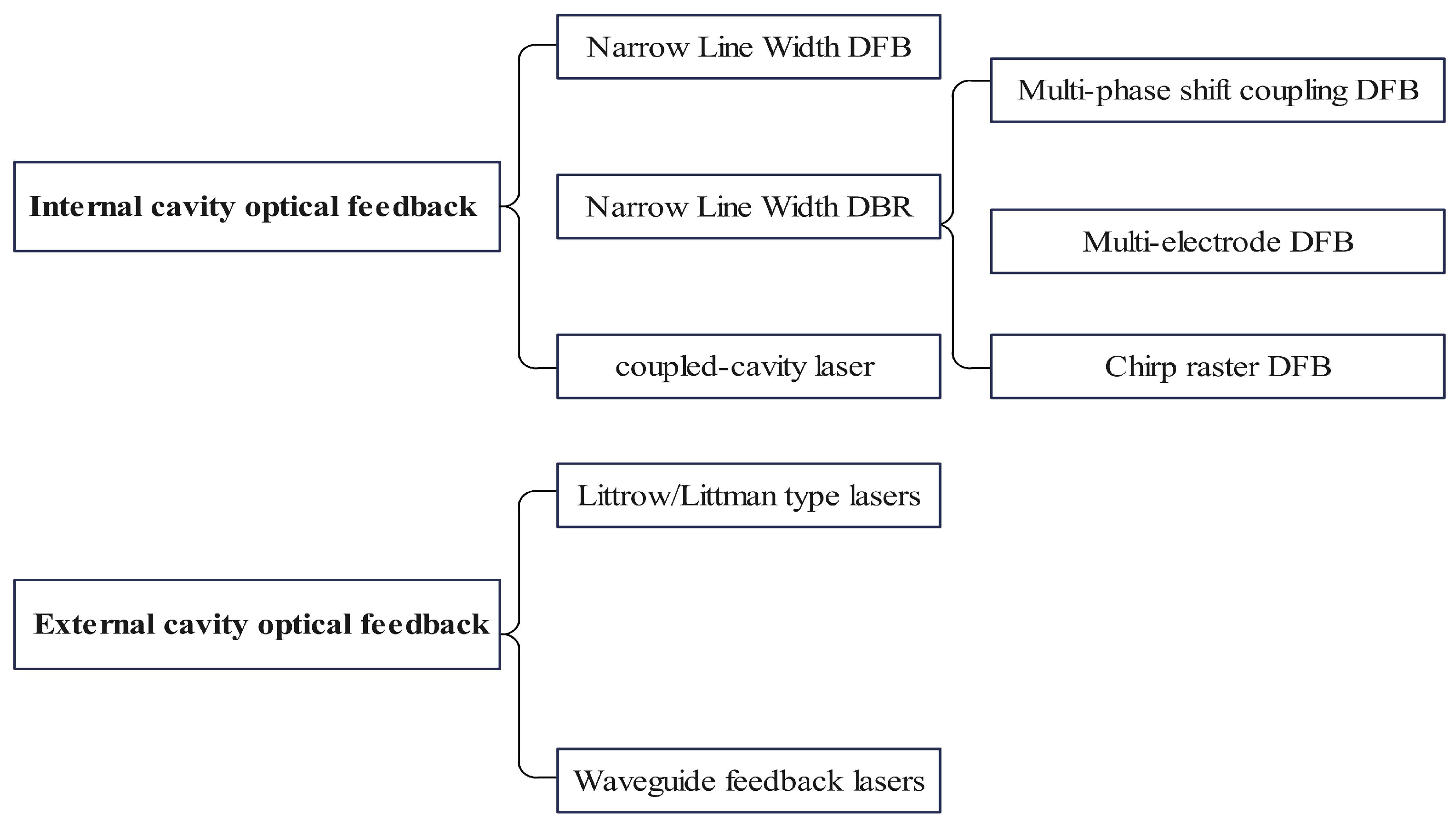
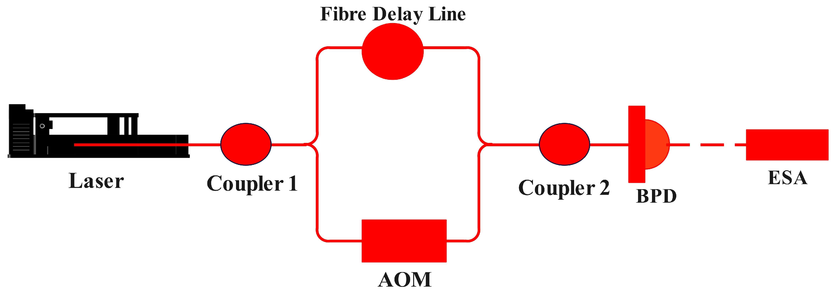
2.3.7. Narrow Linewidth of Light Source

For FMCW LiDAR, the linewidth of the laser has a great impact on the range performance of the radar. This parameter represents the coherence of the laser and determines the theoretical detection range and accuracy. The use of a narrow-linewidth light source reduces the complexity of the processing circuitry, improves the stability of the optical communication system, and reduces the receiver bit error rate (BER) [29,30]. Therefore, the light source used for FMCW LiDAR requires narrow linewidth, frequency stability, low power consumption, and a long lifetime.
Narrow linewidth semiconductor laser technology is mainly divided into two categories: internal cavity optical feedback technology and external cavity optical feedback technology [31], as shown in Figure 8. Internal cavity optical feedback mainly includes distributed feedback laser (DFB) lasers and distributed Bragg reflector (DBR) lasers with a feedback mechanism. The purpose of this technology is to inhibit the spectral linewidth of the laser. The Bragg grating of the DFB laser is distributed along the length of the cavity, and the intracavity optical field is influenced by the grating to form a forward field by part of the transmission and a backward field by part of the reflection. During transmission, the two optical fields continuously couple with each other, acquiring gain and generating stimulated emission of radiation for light amplification. DBR lasers are designed with a high-reflectivity Bragg grating at one end face of the resonant cavity, the gain longitudinal mode wavelengths are selected to obtain strong feedback by optimizing the Bragg spectra, and single mode excitation is formed inside the resonant cavity.
In uniform grating DFB lasers, the two longitudinal modes have the same low threshold gain near the Bragg wavelength, so there is usually a problem of dual-mode degeneracy. To solve this problem, the researchers proposed quarter-wavelength phase-shifted DFB lasers, which allow for single-mode excitation [32]. However, the introduction of a quarter-wavelength phase-shifted region in the uniform grating is equivalent to adding defects to the periodic structure, where the strong coupling of the optical field leads to the concentration of longitudinal photons in the phase-shifted position, producing a more severe spatial hole burning effect. This uneven distribution of photons makes the intracavity refractive index have a large perturbation, which ultimately causes the longitudinal mode frequency noise increases and spectral line broadening and other problems [33,34]. To solve this problem, researchers have conducted a number of investigations. For example, the narrow linewidth DFB laser structure can be divided into multi-phase shift-coupled DFB narrow-linewidth laser, multi-electrode injection DFB, and chirp grating DFB, among others. Narrow linewidth DFB lasers are compact in structure and achieve single longitudinal mode excitation with the help of Bragg grating frequency selection, which has high side mode rejection ratio and high-speed direct tuning capability. By overcoming the chirp effect of the direct tuning frequency, narrow-linewidth DFB lasers are the first choice for building high-performance optical communication systems. Arrays of multiple DFB lasers combined with couplers and amplifiers enable the design of complex on-chip light sources. The use of high-speed external modulation in combination with narrow-linewidth DFB lasers enables the design and implementation of high-performance coherent optical transmission and reception systems.
External cavity feedback technology utilizes external optical components to provide feedback and wavelength selection to the emitted light from semiconductor laser chips, thereby extending the effective length of the resonant cavity. Optimization of the passive region enhances the laser’s quality factor (Q-value) and reduces spectral linewidth. The use of passive optical components for frequency selection and feedback facilitates lower phase noise and improved temperature stability. Recently, there have been an increasing number of reports on the design of external cavity feedback lasers using SOI passive optical waveguides. The design and fabrication of high-refractive-index-difference nano-waveguides based on the SOI platform is more advanced in terms of device simulation methods and process preparation, and various passive devices such as couplers, multimode interference beam splitter, filters, and AWG array wave-guide gratings have been designed. Using the low-loss silicon waveguide design and the preparation of high-Q passive external cavity structure, combined with the III–V gain materials, narrow linewidth heterodyne integrated semiconductor lasers can be designed on a silicon substrate. Using silicon heterogeneous integration technology, III–V materials or other incompatible materials can be transferred to silicon wafers, which can meet the optimized design requirements of practicality and scalability while ensuring the higher performance of III–V and the advantages of SOI waveguide platforms.
A comparison of common semiconductor narrow-linewidth lasers is shown in Table 2.
In addition, in the LiDAR field, narrow-linewidth lasers are tested for linewidth indirectly using the auto-differential method and frequency monitors. The inability to use a spectrometer for direct linewidth testing is primarily because the spectrometer is based on a grating for testing and its limits the measurement accuracy to linewidths on the order of pm, which translates to a linewidth in the GHz range, and is therefore insufficiently precise for direct linewidth testing. Figure 9 illustrates the system architecture of the autocorrelation linewidth test. The two key components are the fiber delay line (FDL) and the acousto-optical modulator (AOM). The FDL provides the amount of delay, while the AOM is used for frequency shifting, shifting the center frequency after coherence from zero-frequency to high-frequency to avoid interference from low-frequency signals.

2.3.8. Technical Limitations of FMCW LiDAR and Their Impact on Key Parameters

Although the FMCW LiDAR technology is relatively mature, researchers continue to explore methods by which to address its limitations and advance the technology further. We have systematically summarized and deeply analyzed the key performance parameters of FMCW LiDAR, demonstrating how these parameters collectively shape the overall performance of the LiDAR system, as shown in Table 3.
From the analysis in Table 3, the metrics of FMCW LiDAR are mainly limited by the performance parameters of the light source. Therefore, current research on FMCW LiDAR focuses on exploring more-advanced light source technologies to improve the overall stability of the system. By improving the design of the laser light source and receiver and developing more advanced ambient noise filtering algorithms, the environmental adaptability of the system can be significantly improved, and new types of laser light sources, such as ultrafast lasers and quantum dot lasers, can be explored to provide a more stable and wider frequency modulation range. OPA technology allows for laser beams to be scanned electronically without mechanical moving parts. This technology can significantly reduce system size and weight, improve reliability, and potentially reduce costs. In addition, improvements in OPA technology also help improve angular resolution and scanning speed.
To optimize these key parameters, researchers are currently developing more-efficient signal processing algorithms to improve modulator and receiver performance; more precise wavelength control and high-speed modulation techniques are used to significantly improve radar performance, and it should be noted that, for intracavity modulated continuous-wave laser sources, achieving a high tuning rate and narrow linewidth simultaneously presents an inherent trade-off. A longer resonant cavity facilitates the attainment of a narrower linewidth but compromises the tuning speed. Conversely, a shorter resonant cavity can enhance the tuning rate, but at the expense of expanding the linewidth of the laser source [35].
In addition, we give the source factors of potential degradation of FMCW LiDAR performance as shown in Table 4 [36].

3. FMCW LiDAR Research Progress

The cutting-edge trends in FMCW LiDAR technology are focused on enhancing detection precision and range, improving signal processing, optimizing frequency modulation linearity, and employing narrow-linewidth techniques. Through these technological advances, researchers are able to enhance the performance of LiDAR systems significantly, better adapting them to complex and dynamic application environments. Additionally, improvements to laser light sources can optimize overall system performance and data quality. Collectively, these efforts are poised to advance the development of FMCW LiDAR technology greatly, propelling its applications in critical areas such as autonomous driving and safety monitoring.

3.1. Progress in Detection Accuracy Research

The ranging accuracy of FMCW LiDAR systems constitutes a pivotal aspect of their technical performance. Accurate distance measurement not only significantly impacts the system’s responsiveness and decision-making accuracy but also serves as a crucial element in enhancing overall safety and reliability. As automation and intelligence levels advance, the high-precision ranging capabilities of FMCW LiDAR are increasingly becoming the cornerstone of technological progress in these domains. Therefore, rigorous investigation and enhancement of FMCW LiDAR’s ranging accuracy are imperative not only to meet the evolving technical demands but also to comply with increasingly stringent industry standards and application requirements.
In 2018, Tong et al. [37], from Tianjin University, proposed an innovative amplitude modulation technique to correct the nonlinear error introduced by the frequency sweep source in FMCW LiDAR systems. By implementing this method, the research team successfully developed a ranging system, as shown in Figure 10, which consists of two cascaded fiber Mach–Zehnder interferometers to improve measurement accuracy and stability. The first interferometer generates a sine wave signal with equidistant frequency peaks, while the second interferometer decomposes these carrier signals into multiple components and recombines them into a mixed beat signal, which allows for the mixed beat signal to be amplitude-modulated according to the signal returned from the measurement path. The system operates in a sweep bandwidth range of 1540 nm to 1560 nm, ensures adequate frequency resolution to correct nonlinear frequency sweep errors effectively and improve measurement accuracy. Experimental results show that the system achieves a range resolution of 69 µm, a stability of 2.9 µm, and an excellent ranging accuracy of 4.3 µm within a range of 1 m. This method can effectively suppress nonlinear errors and eliminate phase differences caused by the mismatch between the clock and measurement signal sampling time. This achievement not only demonstrates the potential of amplitude modulation methods in enhancing the performance of FMCW LiDAR systems but also provides a feasible method for precise ranging.
In 2019, Poulton and colleagues at the Massachusetts Institute of Technology significantly expanded the application of FMCW LiDAR by introducing OPA-based technology for coherent ranging and velocity measurements, marking a crucial shift from laboratory experiments to practical applications. The team innovatively utilized two passive large-scale optical phased array chips to construct a prototype FMCW LiDAR system. This system demonstrated its capability by simultaneously measuring the range and velocity of a rotating umbrella at a distance of 25 m, showcasing the first successful application of OPA-based technology in coherent LiDAR operations. Furthermore, the team conducted a one-dimensional OPA ranging experiment, successfully detecting pedestrians at a distance of 185 m. Additionally, by employing two active OPA chips, the researchers achieved three-dimensional depth detection up to 12 m, with the point cloud results of a person at 7 m clearly illustrated, further proving the system’s efficient performance and potential for broader applications [38].
In 2020, Riemensberger et al. from the Swiss Federal Institute of Technology in Zurich introduced a new FMCW LiDAR technology [39]. This novel technology employs micro-resonator optical soliton frequency combs, enabling large-scale parallel FMCW measurements. As demonstrated in Figure 11, the system excelled in simultaneous ranging and velocity assessments. During trials targeting an object 11.5 m away, the system achieved exceptional ranging precision, attaining an accuracy of 1 cm.
In 2021, researchers at Shanghai Jiao Tong University developed an innovative LiDAR system, leveraging a silicon dual-parallel Mach–Zehnder modulator (DP-MZM) for FMCW signal generation [40]. This system, distinguished by its use of generated triangular wave modulation signals, demonstrated the capability for concurrent ranging and velocity measurements. During experiments with a target positioned 2.2 m away, the system demonstrated high-precision measurement capabilities, achieving a ranging resolution of 13 mm and a velocity resolution of 0.5 m/s.
In 2022, a team from the University of California designed a composite focal plane switch array [41]. This innovative array combined a grating antenna with light-switch array technology customized for microelectromechanical systems (MEMS), featuring an advanced structure with 128 × 128 elements. Integrating a highly sophisticated chip with FMCW ranging technology, the research team accomplished precise distance measurements for targets within a 0.8 m to 10 m range, achieving a ranging accuracy of 1.7 cm. This study underscored the significant potential of focal plane switch arrays in enhancing ranging accuracy.
In 2023, researchers from Pengcheng Laboratory in Shenzhen, in collaboration with Jilin University, developed an innovative FMCW LiDAR system based on optical frequency shifting [42]. By employing the linear scanning of optical frequencies and frequency shifts induced by an AOM, the system is capable of accurately measuring both the distance and velocity of targets. The distance is calculated from the frequency difference in the beat signal generated during operation. The introduction of frequency shifts by the AOM enables the differentiation between static and dynamic targets, thereby enhancing the precision of distance measurements. Furthermore, the relationship between the mean frequency of the beat signal and the frequency shifts introduced by the AOM enables the calculation of the target’s radial velocity. The direction of rotation of the target is determined by comparing the magnitude of the average frequency to the frequency shift caused by the AOM. Experimental demonstrations demonstrated the real time measurement of a disk rotating at 26.43 m/s at a distance of 1.267 m, achieving distance and velocity measurement accuracies of 16 mm and 0.037 m/s, respectively. The system is not only capable of accurately measuring the distance and velocity of targets, but it is also able to determine their rotation direction directly, thus improving measurement efficiency, as shown in Figure 12.
Although current FMCW LiDAR technology has made remarkable achievements in ranging accuracy, it still faces challenges in maintaining such high accuracy in extreme environments. In particular, harsh climates and changing conditions have become key factors restricting its widespread application. With the continuous emergence of new materials and advanced technologies, more innovative solutions are expected to be developed in the future. These solutions not only need to improve the accuracy of ranging and speed measurement further but also must ensure stability in extreme environments. These technological advances will expand the application areas of FMCW LiDAR and meet a wider range of practical needs, thereby pushing the entire field to higher standards.

3.2. Progress in Signal Processing Research

In order to optimize ranging performance and overcome the influence of environmental factors, and because traditional methods are often limited by hardware performance and algorithm adaptability, researchers are constantly exploring more advanced signal processing algorithms and system designs.
In 2020, a team from Yokohama National University in Japan made significant progress in silicon-based modulator technology by developing an in-phase/quad-phase (I/Q) modulator [43]. This modulator integrates a compact photonic crystal phase shifter, efficiently producing carrier-suppressed single-sideband modulated signals. By finely adjusting the frequency and phase of the modulating signal through precise timing control, the researchers achieved a frequency-modulation performance characterized by a side-mode rejection ratio of 22.3 dB. This technology not only improves the modulation efficiency of the signal but also effectively addresses the performance degradation problem of traditional modulators in complex environments.
In 2021, Cheng et al. [44] improved the empirical mode decomposition (EMD) algorithm by introducing a novel correlation coefficient criterion based on differential terms for the meticulous selection of effective intrinsic mode functions (IMFs). Additionally, they combined singular value decomposition and wavelet denoising techniques for echo signal-processing, successfully elevating the signal-to-noise ratio from 5.28 dB to 21.06 dB. This innovative methodology in signal-processing significantly reduces the impact of noise, marking a substantial advancement in the field.
In 2022, researchers from Tsinghua University [45] undertook a comparative study of wavelet analysis and the short-time Fourier transformer (STFT) within the context of time–frequency analysis applications for FMCW LiDAR systems. The results indicated that although STFT boasts superior resolution and measurement accuracy, wavelet analysis excels in temporal and lateral resolutions and demonstrates a superior ability to filter noise compared to STFT. In 2019, the Hefei Institute of Physical Science of the Chinese Academy of Sciences [46] proposed a novel denoising method called the WT-VMD algorithm. This method merges the sparrow search algorithm (SSA) with variation mode decomposition (VMD), tailored specifically for LiDAR signal-processing. Testing on simulated LiDAR signals with 50, 100, and 1000 pulses showcased significant improvements in SNR, root mean square error (RMSE), and smoothness indicators. Specifically, signal-processing resulted in SNR improvements of 138.5%, 77.8%, and 42.8%, and reductions in root mean square error (RMSE) of 81.8%, 72.0%, and 68.8%, respectively. For aerosol and cloud signals, the SNR increased by 83.3%, 60.4%, and 24.0%, while the RMSE decreased by 70.8%, 66.0%, and 50.5%, respectively. The WT-VMD SSA-based joint algorithm is based on the dual needs of improving processing efficiency and accuracy. It optimizes the limitations of traditional algorithms in processing complex signals. It shows excellent performance in the denoising of actual LiDAR signals and effectively improves the accuracy of LiDAR signals.
In 2023, the Tianjin University proposed a target information solving method and system for FMCW LiDAR to improve data processing efficiency and reduce hardware load [47]. In this method, the intermediate frequency (IF) signals in the up-sweep and down-sweep are first downsampled and processed by low-pass and high-pass filters, respectively. Power spectrum measurements are performed on the outputs of the low-pass and high-pass filters. The output of the high-pass filter is digitally down-converted. A dataset containing the target information is filtered after comparing the power spectrum measurements of the low- and high-pass filters. After further downsampling processing of this target dataset, an FFT is performed to determine the location of the maximum power spectrum, which is reduced by the frequency compensation value. Finally, spectrum accumulation and information resolution are employed to obtain the distance and velocity information of the target. This technical solution not only optimizes the use of hardware resources but also significantly improves the data processing speed.
By introducing more advanced algorithms and system designs, researchers can effectively improve radar signal stability and optimize data processing speed. Advances in these technologies enhance the ability to adapt to environmental changes and ensure accurate transmission and processing of data, thus ensuring the reliability and practicality of radar systems in diverse application scenarios. With the continuous advancement of signal processing technology, the application fields of FMCW LiDAR have been significantly expanded and can better meet actual needs, such as industrial and safety monitoring.

3.3. Advances in FM Linearity Research

The performance of an FMCW LiDAR is also limited by its FM linearity. Optimization of FM linearity not only improves the accuracy of range and speed measurement but also is critical to the stability and reliability of the overall system. With the advancement of technology and the increase in application requirements, improving FM linearity has become a necessary means of achieving higher system performance. Therefore, in-depth study and optimization of FM linearity is the key to ensuring the best performance of FMCW LiDAR in automation and intelligent applications. Researchers have endeavored to enhance linearity through innovative techniques and approaches, such as the use of novel tuned light sources and improved FM strategies, to meet the increasingly stringent technical standards and application requirements.
In 2018, researchers at Tianjin University [48,49] introduced a novel approach that combines cyclic frequency shift loop technology with swept-frequency tuning of a light source. Utilizing a continuous laser with an accuracy of up to 20 kHz as the seed light source, this method employs an optical switch to generate square-wave pulse light with a 5.5 µs period and a 343.75 ns duration. The technique stabilizes the pulse frequency in the cycle to a 12.5 GHz shift, creating a series of 16 optical pulses that incrementally vary over time. This approach achieves continuous frequency conjunction in the frequency domain, facilitating linear frequency tuning up to 200 GHz. External modulation is employed to preserve the narrow-linewidth characteristics of the seed light, maintaining the linewidth of the emitted light below 50 kHz and ensuring high coherence. This development of a narrow-linewidth, wide-band light source presents new prospects for high-resolution, long-distance imaging in FMCW LiDAR applications, boasting distance resolutions of less than 1 mm and detection ranges of over 1 km, thus paving the way for advanced long-distance high-resolution LiDAR technologies.
In 2019, the University of California, USA [50], pioneered a new technique aimed at enhancing the linearity of laser frequency scanning. This technique uses iterative learning control and predistortion methods to improve laser frequency scanning’s linearity. Demonstrated with a commercial vertical-cavity surface-emitting laser (VCSEL) and DFB lasers, the technique significantly minimized the relative residual nonlinearity of frequency scanning to less than 0.005%, marking a substantial improvement in the precision and reliability of frequency scanning processes.
In 2020, the Shanghai Institute of Optics and Precision Mechanics of the Chinese Academy of Sciences developed a high-precision 3D FMCW LiDAR system in which state-of-the-art MEMS scanning technology was used [51]. The system utilizes a self-developed arbitrary waveform generator, optoelectronic modulator, and optical filter to generate a linear FMCW signal with a bandwidth of 2.0 GHz and a pulse repetition frequency of 100 kHz. By combining outlier coherent detection with MEMS scanning techniques, the system greatly improves the sensitivity. In addition, in order to obtain distance and fast imaging of targets with a large dynamic range, a multiphase FFT is employed to calculate the full frequency band. The multiphase FFT algorithm can make full use of the hardware resources of FPGA to improve the real-time performance, thus effectively increasing the number of channels and realizing the parallel processing of FFT. Rigorous testing of static and dynamic target imaging scenarios shows that the system is capable of capturing 3D images at 40 fps, which meets the high-speed imaging requirements of various applications. To demonstrate the performance of the system, the research team sampled the frame data images at 1 s (10 frames/s) intervals, as shown in Figure 13a. At this point, the motion state at different moments can be seen more clearly. The speed of human movement measured at the same time was 1.5 m/s. The 3D image in Figure 13a is processed via simple filtering. Again, the colors represent the depth of the distance.
Thereafter, the slow scanning time of the MEMS scanner was further reduced. The period of the slow scan was adjusted to 40 Hz; i.e., the 3D image was acquired at a rate of 0.25 s (40 frames/s). Figure 13b shows the result of a 3D image at a slow scanning period of 40 Hz with 50 pixels × 50 pixels per frame. The colors reflect the reflectivity of the target. As can be seen from the results, the spatial resolution in the slow scanning direction is relatively low compared to 10 fps imaging. However, the final 3D imaging result is still clear enough. Similarly, the undisplayed 3D images were extracted and displayed at intervals of 0.25 s.
In 2022, a research team from Shanghai Jiao Tong University [52] developed an all-solid-state FMCW LiDAR system, incorporating beam-steering with lens-assisted technology to achieve a ranging capability of up to 210 m. Utilizing directly modulated DFB lasers for high-bandwidth performance and cost-efficiency, the team enhanced frequency scanning linearity through precise predistortion drive voltage adjustments for the DFB lasers. Achieving a nonlinear residual ratio of 1−r2 at 5.19 × 10⁻⁸, the system demonstrated efficient performance. Operating at a wavelength of 1550 nm, the system was validated with 16 scanning directions, a beam-steering step of 0.35°, and a total steering angle of 1.05°. By optimizing the transmit array and lens configuration, the system can achieve a wider scanning range and larger scanning angle. Phase-noise compensation technology enables excellent spatial resolution even beyond the laser’s coherence length, demonstrating its applicability in long-range measurement scenarios.
In 2023, the Chinese University of Hong Kong’s research team [53] developed a laser-ranging system utilizing dynamic FMCW technology and optical coupling through a rotating interface, addressing beat frequency issues in traditional FMCW LiDAR. By employing a fiber-optic rotary joint and real-time laser chirp nonlinearity corrections vis synchronous laser injection current and FMCW signal adjustments, the system eliminates rotational coupling-induced measurement deviations. This FMCW LiDAR system excels in high-precision ranging during low-speed rotation, achieving a rapid capture rate through the linearization of laser frequency-modulation in each frequency sweep, outperforming the rotational speed of the fiber-optic rotary joint. Capable of rotating clockwise and counterclockwise, it consistently generates clear, robust beat frequency signals over a 50 cm measurement distance. Additionally, the results during rotation demonstrate remarkable consistency with those from stable conditions, with average measured distances of 50.8 cm and 51.4 cm, both within the standard deviation of stable condition measurements. This study presents a new approach for applying FMCW LiDAR technology in dynamic environments.
In 2024, a research team from Yanshan University [54] proposed a novel approach to mitigate the nonlinear frequency scanning issue in FMCW LiDAR light sources by utilizing a hybrid electro-optic phase-locked loop (HEO-PLL) for precise control over the frequency linearity of the DFB laser. The HEO-PLL proves exceptionally effective in controlling DFB lasers during continuous, rapid, and extensive frequency modulation via current tuning, enabling these lasers to function as high-performance light sources for FMCW LiDAR and significantly enhancing the system’s resolution and distance measurement capabilities. The study meticulously discusses the challenges associated with loop bandwidth, center frequency tuning, and the sensitivity to temperature and voltage variations caused by charge pump phase-locked loops. Achieving a scanning speed of 6.78 THz/s and a 0.078% nonlinear triangular wave scan, the research demonstrated a notable 31.49 dB enhancement in beat frequency signal power. This advancement reduces the impact of external temperature and driving signal fluctuations on the laser, facilitating more straightforward adjustments. This innovative approach serves as a vital point and source of inspiration for further progress in FMCW LiDAR technology.
In 2024, a team from Pusan National University in South Korea [55] introduced a laser source for a frequency–wavelength sweep laser (FWSL) and demonstrated a solid-state FMCW LiDAR radar system integrating an FWSL with an acoustic optical deflector (AOD). Demonstrating a coherence length of 1.2 km, a bandwidth of 160 nm, and rapid scanning at 100 kHz at a wavelength of 1535 nm. The system captures high-resolution 4D images of small targets in real-world environments at a real-time frame rate of 200 × 45 pixels per second. This advancement not only enhances LiDAR performance but also opens new possibilities for high-precision remote-sensing.
Although frequency modulation linearity has made significant progress in improving the measurement accuracy and system performance of FMCW LiDAR, achieving fully linear frequency modulation is still a challenge. Current technological progress can already meet certain industrial application needs. However, in wider application scenarios, such as autonomous driving and long-distance space exploration, these technologies still need to be further optimized. Future research will need to focus on developing more efficient modulation techniques and light sources, as well as improving the system’s stability against environmental factors. With the continuous development of new light sources and modulation strategies, the optimization of frequency modulation linearity will not only promote the application of radar technology in traditional fields but also open up more possibilities for the application of radar technology in emerging markets.

3.4. Progress in Narrow Linewidth Research

Narrow linewidth semiconductor lasers have become the ideal light source for the new generation of high-precision LiDAR systems due to their small size, light weight, high efficiency, long life, direct current drive, narrow spectral linewidth and excellent coherence. This type of laser usually integrates a frequency selective structure in the resonant cavity or couples it with an external mode-selective device to accurately control the gain and loss of different wavelengths to achieve effective compression of the spectral linewidth. With the rapid development of technologies such as autonomous driving and remote sensing, the performance requirements for laser sources are becoming increasingly stringent, and research on narrow-linewidth lasers is also constantly deepening.
Optical feedback narrow-linewidth technology is primarily focused on the continual design optimization of various novel devices based on their underlying physical mechanisms to optimize the design for different laser structures, i.e., DFB, DBR, and external cavity lasers that correspond to a different narrow-linewidth implementation method. We utilized two methods with the status of the devices involved in the research to launch a specific introduction and discuss the different technical characteristics and research issues that must be addressed, as shown in Table 5.
In 2014, the University of Ottawa conducted research on multi-electrode surface grating DFB lasers [56], as shown in Figure 14. The structure has three electrodes on the top layer and uses surface gratings for feedback and wavelength selection. Traditional buried grating DFB lasers require secondary growth of the overlying cladding and ridge waveguides using metal-organic chemical vapor deposition (MOCVD) after grating etching, which, to some extent, reduces the single-mode yield and reliability of the device. The advantage of surface grating structures is that they do not require secondary growth processes after grating fabrication. However, challenges include considerations of lateral etch width, Bragg period constancy, and the roughness of the etched surfaces. Step-and-repeat photolithography or electron beam lithography (EBL) is required to achieve high etch precision. The multi-electrode DFB allows for flexible control of the current ratios across the three electrodes and achieves a spectral linewidth of 140 kHz and a single-mode suppression ratio of more than 50 dB in the 1550 nm band, with an output power approaching 7 mW. These results provide important guidance for the fabrication of high-power narrow-linewidth lasers and offer valuable tools for communications and other applications.
In 2014, UCSB developed a slot-coupled cavity narrow-linewidth laser [57]. A deep slot was etched into the ridge waveguide on one side of the cavity to provide sufficient feedback to balance the intracavity losses. The deep-slot waveguide and cleaved facets formed the front and rear mirrors to achieve resonant lasing. The slot parameters, including etch depth, width, and period, were optimized using a two-dimensional scattering matrix approach. This structure is compatible with conventional photolithographic fabrication processes, yielding a slope efficiency of 0.11 mW/mA over a 750 μm cavity length, with a minimum linewidth of 720 kHz at room temperature and linewidth maintained within 1 MHz between 10 °C and 60 °C. The team also proposed an integrated electro-absorption modulated coupled-cavity laser, which, through optimized slot design, achieved a slope efficiency of 0.12 mW/mA and a large signal modulation rate of 3 Gb/s over a 650 μm cavity length, achieving a single-mode suppression ratio of 52 dB near a wavelength of 1500 nm.
In 2017, Tampere University of Technology in Finland designed a 1180 nm narrow linewidth DBR laser [58]. A high-order surface grating with a 2 mm length and a 50% duty cycle was employed as the Bragg mirror, effectively eliminating the need for the regrowth process typically associated with buried grating structures. The Bragg spectral bandwidth was designed around the peak wavelength of the multiple-quantum-well gain, ensuring single-mode lasing. A 3 mm active region was designed to provide sufficient optical gain, and a ridge waveguide width of 3.2 μm was chosen to ensure single transverse mode operation, achieving a 50 dB side mode suppression ratio and effectively preventing mode hopping in the lasing wavelength. The design achieved high output power with a spectral linewidth of 250 kHz.
In 2021, Duca et al., in Italy, proposed a 780 nm narrow-linewidth laser based on a Littrow configuration, which overcame the disturbances in cavity length caused by grating angles compared to previously reported structures of the same type [59]. As a result, using piezoelectric ceramics to adjust the resonant frequency did not directly affect the external feedback unit and the grating selection mechanism, enhancing the ability to suppress mode hopping. This design ultimately achieved a spectral linewidth of 300 kHz.
In 2021, the Xi’an Institute of Optics and Precision Mechanics, Chinese Academy of Sciences, designed an external-cavity, narrow-linewidth, mode-locked semiconductor laser based on a similar structure. Leveraging the strong four-wave mixing effect in the active region and the prolongation of photon lifetime by the external cavity, the device achieved a pulse repetition rate of 10 GHz and an ultra-narrow linewidth of 5.4 kHz [60].
In 2022, Shanghai Jiao Tong University demonstrated a hybrid integrated chip-level external cavity laser, composed of a wide bandgap III–V reflective semiconductor optical amplifier and a low-loss Si3N4 wavelength-selective reflector, as illustrated in Figure 15 [61]. Enhanced laser mode selection was achieved through the tunable Sagnac loop reflector, enabling a record-setting laser wavelength tuning range of 172 nm beyond the free spectral range of the Vernier ring filter, with more than 40 dB single-mode suppression ratio. The Si3N4 platform facilitated a low-loss external cavity, aiding in reducing the laser linewidth to below 4 kHz across the full tuning range. The chip-level laser output power reached 26.7 mW at a wavelength of 1550 nm, providing a broad tuning range and narrow linewidth, making it highly applicable in optical communications, sensing, and photodetection and ranging systems.
In 2023, Weihan Xu and colleagues at Shanghai Jiao Tong University developed a fully integrated solid-state LiDAR emitter [62], resulting in the creation of a high-performance LiDAR system. The team employed a multi-layer silicon nitride platform on a silicon substrate, integrating a widely tunable external cavity laser and a two-dimensional optical phased array based on a 256-channel aperiodic grating. The system achieved an on-chip laser output of 18 mw and high-fidelity beam control by leveraging the high-power handling capabilities and minimal thermal cross-talk of the silicon nitride external cavity lasers. Furthermore, a novel method for compensating for optical path differences was devised to ensure that the beam-forming angles of the phased array remained constant during wavelength scanning. In conclusion, the system emitted light into the free space through the emission aperture, thereby forming a highly directional far-field spot. This research addressed several key challenges inherent to LiDAR systems. Primarily, the employment of silicon nitride external cavity lasers resulted in the achievement of narrow intrinsic spectral linewidths, thereby enhancing the overall performance of the laser. Secondly, the design of the 256-channel optical phased array permitted precise beam control, thereby enhancing the accuracy of the measurements and the capacity to detect targets in the LiDAR system. Moreover, the compensation of optical path differences guaranteed the stability of the beam-forming angles, thereby enhancing the system’s stability and reliability. A broadly tuned single-mode laser output in the 100 nm range was achieved with a 42 dB side-mode rejection ratio, 18 mW output power, and 2.8 kHz linewidth. Two-dimensional beam steering demonstrated a beam divergence of 0.051° × 0.016° over a 140° × 16° field of view. By employing innovative design and integration techniques, this study has resolved critical issues in solid-state LiDAR emitters, thereby providing significant technical support for the realization of high-performance LiDAR systems.
Although narrow linewidth semiconductor lasers have made important progress in improving the resolution and accuracy of LiDAR, the realization of perfect spectral linewidth compression and ultra-high coherence still faces technical challenges. The stability of current technology in high-noise environments and sensitivity to small, reflected signals need to be further improved. Future research needs to focus on developing new semiconductor materials and more-precise frequency control technology to compress the spectral linewidth further and improve the overall performance of the system. These technological advances are expected to expand the application of narrow linewidth semiconductor lasers in FMCW LiDAR, especially in fields such as autonomous driving and environmental monitoring, significantly enhancing their performance and reliability by improving coherence and resolution.

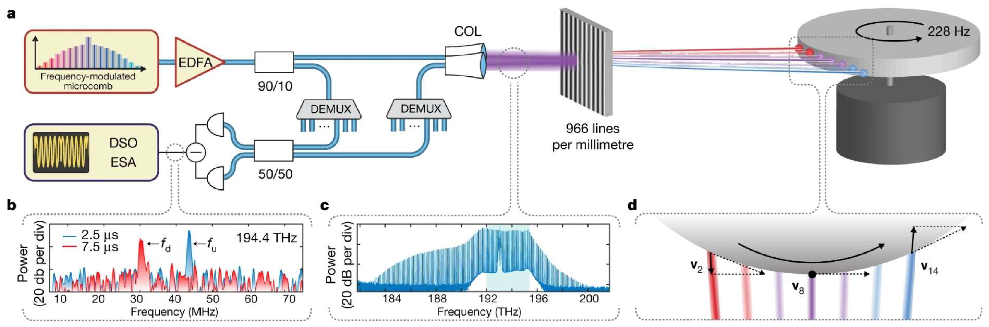
3.5. Research Progress on Integration

One of the primary challenges faced by FMCW LiDAR in its pursuit of technological breakthroughs is the complexity and cost of systems. The application of silicon-based optoelectronic integration technology offers a solution, combining two of the most important inventions of the 20th century (i.e., integrated circuits and semiconductor lasers). Silicon photonics technology, which uses photons as information carriers and is compatible with CMOS processes, integrates optical and electronic devices on a single chip, significantly reducing costs and enhancing compatibility and integration. However, the challenges of developing this technology include high development costs, the increasing complexity of laser modulation, precise coupling alignment, and advanced signal processing techniques. Nonetheless, as silicon photonics chip technology develops, it is anticipated that future FMCW LiDAR systems will be more compact, consume less power, and be more cost-effective, providing a wide range of innovative applications for various industries.
Silicon-based optoelectronic integration technology, as a cutting-edge solution, has demonstrated enormous potential in enhancing radar system performance and reducing costs. By integrating integrated circuit and semiconductor laser technologies, silicon photonics not only optimizes the performance of optoelectronic devices but also greatly enhances the integration and economic efficiency of radar systems. This technological advancement offers a viable path to address the high costs and issues with complexity faced by traditional FMCW LiDAR, while also driving the entire industry toward a higher technological level.
In 2020, Han et al. [63] used a high-resolution remote detection method using uncompensated frequency-modulated continuous-wave sources to forge cost-effective FMCW LiDAR systems. Utilizing economical DFB laser diodes and VCSEL capable of nonlinear optical frequency scanning under conditions of high modulation frequency and integrating these with partial waveform techniques and the maximum power algorithm (MPA), they significantly enhanced the distance resolution of the system, achieving an accuracy of up to 1.93 mm. This work offers a pivotal reference for developing low-cost, high-precision LiDAR detection technologies.
In 2023, the 55th Research Institute of the China Electronics Technology Group Corporation (Nanjing, China) [64] made significant strides in FMCW LiDAR technology by developing and implementing an integrated module for single-channel FMCW LiDAR, aimed at multi-target ranging. This module, distinguished by its innovative integration of solid-state lasers, silicon-based optical phased arrays, and InP-based balanced photodetectors, showcased a core chip measuring just 1.65 cm × 1.65 cm, demonstrating a leap forward in miniaturized design. Achieving a coupling efficiency of up to 62.8% from the laser to the silicon waveguide and a common-mode suppression ratio of 53.08 dB, these advancements not only improve system performance but also significantly enhance ranging accuracy to 8.82 cm. The development of this integrated module represents a new era in the integration and miniaturization of FMCW LiDAR technology, overcoming traditional radar system limitations such as speed, size, and stability. It realizes new prospects for high-speed scanning, low power consumption, and broad applicability in fields such as autonomous driving, robotic navigation, and environmental monitoring.
In 2023, researchers from Korea National University [65] pioneered in enhancing distance recovery in FMCW LiDAR data processing through sweep-frequency heterodyning technology. This innovative approach, extracting beat frequency signals from FMCW LiDAR, exceeds the traditional Nyquist sampling limit, facilitating accurate distance measurements of objects. With sweep-frequency heterodyning, unambiguous measurements were achieved for distances ranging from 1.06 m to 6.34 m, using a sweep-frequency range of 1 MHz to 6 MHz. This technological breakthrough not only transcends the Nyquist limitation for precise distance measurement but also considerably expands the measurable distance range, offering more flexibility and possibilities for FMCW LiDAR applications by adjusting the measurement distance range and resolution with different sweep bandwidths.
In 2023, Zhuhai Yingxun Xinguang Technology Co., Ltd. (Zhuhai, China) disclosed a chip-integrated FMCW LiDAR system [66] that employs an external-cavity tunable laser composed of an emitting gain chip, first and second integrated optical waveguides, a broadband optical feedback structure, a waveguide phase tuning control area, an adjustable waveguide filter, a collimating optical lens, and an optical filter feedbacker. This design features a simple, reliable, and rapid laser beam wavelength tuning mechanism. By incorporating an optical converter and multiple free-space optical feedback channels, the system achieves wavelength tuning and directional selection over a broader wavelength region and range. Dispersion optical components are used to enable solid-state laser beam angle scanning driven by wavelength tuning without mechanical movement. Wavelength tuning linearity or chirp of the external-cavity tunable laser is monitored, calibrated, and controlled using a waveguide interferometer and a photonic balanced detector. FMCW coherent laser ranging is achieved using a focusing optical lens, a waveguide interferometer, and a photonic balanced detector. This semiconductor chip-based LiDAR solution offers high cost-effectiveness for advanced ranging and 3D sensing applications such as autonomous driving.
In 2024, SiFotonic Corporation (Hangzhou, China) demonstrated its independently developed four-channel dual-polarization FMCW LiDAR receiver module based on a silicon photonic coherent receiver chip [67]. Each channel is capable of processing light signals with dual polarization. This module is a joint package of silicon photonic coherent receiver chips and TIA chips, integrating edge couplers (EC), polarization beam rotation splitters (PBRS), 180° optical mixers, and balanced Ge/Si waveguide PD pairs. In terms of performance, the common-mode rejection ratio (CMRR) of each channel exceeds 30 dB, and the polarization extinction ratio (PER) surpasses 31.5 dB, which are significantly advantageous within the wavelength range of 1540 nm to 1560 nm. Importantly, the module exhibits a high sensitivity better than −80 dBm, enabling precise ranging operations up to 81.9 m. This work also demonstrates the potential of higher linearity FM lasers to further enhance the performance of FMCW LiDAR systems.
In 2024, researchers Lei Yu and Pengfei Wang from the Institute of Semiconductors, Chinese Academy of Sciences, developed a novel focal plane array (FPA) chip design [68]. The design incorporates a single antenna for the emission of laser beams and an antenna array for the reception of return signals. The deployment of a single antenna for emission, in conjunction with the array for signal reception, enhances the directivity of the antenna system, achieving a theoretical directivity of 91.6%. The routing of light beams is managed via an array of micro-ring switches, which control the beam by aligning the resonant wavelength of the micro-rings with the incoming light wavelength, thus enabling precise beam manipulation. The FPA chip is integrated with an auxiliary lens system that collimates and deflects the beam for two-dimensional scanning. The integrated antenna array markedly enhances the range-finding capabilities of the FPA, as evidenced by the high SNR sustained over a distance of up to 11 m, thereby improving the precision of distance measurement. The implementation of an all-solid-state structure negates the necessity for mechanical components, simplifies the system design, and reduces both complexity and cost. This innovative approach offers a scalable solution that enhances system reliability and stability through an integrated design and optimised antenna array, thereby providing a technological foundation for the development of large-scale solid-state LiDAR systems.
Although silicon-based optoelectronic integration technology has made remarkable achievements in improving the integration and cost-effectiveness of FMCW LiDAR systems, there are still a series of technical challenges in achieving high-performance and highly integrated radar systems. Current research progress has demonstrated the great potential of integration technology in system miniaturization, cost reduction and performance improvement. However, the design of highly integrated systems has extremely high requirements for manufacturing precision and materials and is highly dependent on the perfection of the design and manufacturing processes. Future research will need to focus on optimizing optoelectronic integration design, improving the precision and reliability of manufacturing processes, and developing new materials and technologies to reduce costs and improve system performance. With the continued advancement of these technologies, it is expected that silicon-based optoelectronic integration technology will be more widely used in more fields such as autonomous driving, aerospace and environmental monitoring, further promoting the development of FMCW LiDAR technology towards a more efficient, economical, and intelligent direction.

3.6. The Future Direction of FMCW LiDAR Technology

With the rapid advancement of FMCW LiDAR technology, significant progress has been observed in key areas such as ranging accuracy, signal processing, frequency modulation linearity, narrow linewidth technology, and system integration. Despite these achievements, challenges remain, particularly in applications under extreme conditions and in the development of high-performance systems.
First, although improvements in ranging accuracy have been substantial, maintaining this precision in extreme environments continues to be problematic, necessitating support from novel materials and advanced technologies to ensure stable operation under diverse climatic conditions. Second, enhancements in signal processing have bolstered radar stability and data handling capabilities, supporting the use of LiDAR technology in sectors like industrial monitoring and security. Additionally, research in frequency modulation linearity and narrow linewidth technologies is pushing the performance boundaries of LiDAR systems, especially in demanding applications such as autonomous driving and long-range detection.
These advancements in technology have not only facilitated the widespread application of LiDAR systems in terrestrial environments but also demonstrated unique potential for use in space environments. FMCW LiDAR systems aboard spacecraft offer precise distance measurement and target detection, owing to their superior range accuracy and signal processing capabilities, which are well-suited to the extreme temperatures and radiation conditions encountered in space. Specifically, this technology can be utilized in Earth observation satellites to achieve high-precision surface monitoring and atmospheric sensing, thereby enhancing the accuracy and reliability of satellite data.
The U.S. National Aeronautics and Space Administration’s (NASA) Amzajerdian et al. [69] have developed a fully fiber-optic linear FMCW coherent LiDAR system designed to support NASA’s new space exploration programs, including crewed and robotic missions to the moon and Mars. Compared to traditional pulse laser altimeters or rangefinders, this fully fiber-optic coherent LiDAR system offers a significant advantage by directly measuring platform velocity through the extraction of Doppler frequency shifts, rather than relying on time-of-flight measurements. This approach avoids errors introduced by terrain features such as hills, cliffs, or slopes. The Doppler measurement precision is two orders of magnitude higher than that of pulse laser altimeter velocity estimates. The system comprises frequency-stabilized fiber lasers, high-power fiber amplifiers, fiber-coupled telescopes, fiber optics, balanced detectors, and processors. The fiber amplifiers amplify the laser signal and split it into three parts to distribute power to three telescopes on the sensor’s optical head. These telescopes collect ground signals and transmit them via fiber optics to three pairs of balanced detectors. The outputs from the detectors are processed by a receiver based on a Pentium Dual Core processor, which can either store timing data for post-processing or provide real-time distance and velocity measurements. The system utilizes an FMCW laser emitter to produce linearly modulated triangular waveforms and employs optical mixing to use a portion of the emitted beam as the local oscillator (LO) for the optical receiver. Mixing the LO field with the delayed received field yields a time varying IF that is directly related to the target distance. The system enables high-resolution distance measurements and, through a multi-channel reception setup, provides precise horizontal and vertical velocity measurements. Experimental results indicate that the LiDAR achieves a distance measurement accuracy of 1 cm and a velocity measurement accuracy of 1 cm/s.
In conclusion, although current FMCW LiDAR technology has achieved multiple milestones, further research and innovation in materials, technology, and design are essential to broaden its applications. Such efforts are expected to better align FMCW LiDAR with future technological demands and market shifts, thereby driving the industry towards greater efficiency, economy, and intelligence.

4. Conclusions and Outlook

As the demand for FMCW LiDAR technology in both civilian and military sectors continues to grow, the performance requirements for this technology are also increasingly stringent. Future development trends are expected to focus on miniaturization, enhanced integration, reduced power consumption, and continuous optimization for long-range detection, high resolution, high accuracy, and robust real-time capabilities. These advancements pose greater demands on the performance of FMCW LiDAR systems. Owing to its broad measurement range and strong anti-interference capabilities, as well as its ability to measure speed directly based on the Doppler effect, FMCW LiDAR is increasingly regarded by researchers as an ideal choice for future technologies. Several companies, such as Aeva, Aurora, and SiLC, have achieved significant results in this field and have received substantial support and investment from numerous automobile manufacturers.
Aeva’s Atlas™ is the world’s first automotive-grade 4D LiDAR with simultaneous velocity and range detection. Combining ultra-long range and unmatched resolution, Atlas delivers industry-leading performance for high-volume automotive applications, enabling the breakthrough of L3 highway speed driving for advanced driver assistance systems (ADAS) and autonomous vehicles. The system is capable of a detection range of 250 m at 10% reflectivity, with a maximum range of 500 m; has a 120° horizontal by 30° vertical field of view; is stable over a wide range of operating temperatures from −40 °C to 85 °C; complies with ISO 26262 ASIL-B (D) [70] level automotive safety standards; has a compact design that is up to 70% smaller than traditional LiDAR; and utilizes passive cooling technology for power efficiency. These features give the Atlas™ a significant competitive advantage in the field of autonomous driving and ADAS [71]. Aurora’s FirstLight LiDAR represents an advanced FMCW LiDAR technology that enhances the safety deployment of autonomous vehicles through integrated photonics. The FirstLight LiDAR features an exceptionally long detection range, capable of detecting objects over 400 m away, providing the Aurora Driver with additional reaction time. By utilizing the Doppler effect, FirstLight LiDAR delivers real-time velocity information for each detection point, aiding in rapid identification and response planning. The integration of photonics technology transforms complex optical components into semiconductor chip-level devices, improving manufacturing scalability. Aurora not only enhances the scalability of LiDAR production but also anticipates significant cost reductions, making mass production feasible. Aurora plans to implement this technology in autonomous truck fleets by 2027, further advancing autonomous driving technology. With the proprietary long-range capabilities of FirstLight, combined with Aurora‘s ability to scale the technology, Aurora has the only LiDAR solution that will unlock high-speed self-driving at scale, making FirstLight the highest-performance automotive-grade LiDAR available for the driverless market [72].
SiLC has integrated unique photonic technology to develop the Eyeonic vision system, the industry’s most compact and powerful FMCW LiDAR machine vision solution. The system offers the highest resolution, accuracy, and detection range and is the only FMCW LiDAR solution that provides polarization information. Eyeonic vision systems are available for a variety of distance requirements: short-range (SR) Eyeonic vision systems, optimized for ranges up to 50 m with millimeter-to-sub-millimeter depth accuracy, ideal for high-precision AI machine vision tasks such as pallet and truck loading or product inspection; medium-range (MR) Eyeonic vision systems, optimized for ranges up to 150 m, offering 3D ranging, dual polarization, and instantaneous velocity with industry-leading accuracy for home security and factory automation applications; long-range (LR) Eyeonic vision systems, effective at ranges up to 300 m, providing instantaneous velocity detection and excel in dynamic object classification and prediction for applications such as ADAS, self-driving cars, outdoor industrial automation, smart infrastructure, and mapping; and ultra-long-range (ULR) Eyeonic vision systems, providing visual inspection from 500 m to over 1 km with leading angular resolution, range, and velocity accuracy, designed for applications such as drone tracking, perimeter security, and aircraft ground control [73].
In the future, with advancements in materials science and microelectronics technology, it is anticipated that more-compact, higher-performance, and lower-cost FMCW LiDAR systems will be developed. These advancements will further expand their range of applications. Continued research and development of silicon-based optoelectronic integration technology is crucial for achieving higher performance in FMCW LiDAR systems. This is not only an inevitable trend in technological innovation but also a key step in driving modern technology towards broader applications. Therefore, in-depth research and technological development in this field will open up more possibilities for implementing efficient, economical, and intelligent sensing technologies.
This study comprehensively discusses the core parameters of the FMCW LiDAR system, covering key parameters, including detection distance, accuracy, ranging precision, modulation linearity, and narrow linewidth, and emphasizes their significance to system performance. The performance indicators of FMCW LiDAR are primarily limited by the performance parameters of the light source, thus generating a superior light modulation signal is also a focal point for FMCW LiDAR researchers. This discussion includes the roles of these parameters in the integrated system and provides a reference analysis for multi-parameter joint optimization, aimed at supporting future decisions in the integration process of FMCW LiDAR systems. This will focus attention on key parameters and their interactions during the design and optimization process, offering reliable references for making more informed choices.

Author Contributions

Conceptualization, Z.W. and Y.S.; methodology, J.L. and H.S.; validation, M.S. and H.Z.; formal analysis Y.C., C.Q. and Y.L.; investigation, Y.S., L.L. and P.J.; resources, L.W., Y.N., L.Q. and J.Z.; writing—original draft, Z.W.; writing—review and editing, Y.C. and Y.S.; supervision, C.Q., Y.C. and L.W.; project administration, Y.W. and J.L.; funding acquisition, Y.S. All authors have read and agreed to the published version of the manuscript.

Funding

This work received support from the Science and Technology Development Project of Jilin Province [Grant No. 20220201072GX], the Outstanding Scientific and Technological Talents Project of Jilin Province [Grant No. 20230508097RC], the Science and Technology Development Project of Jilin Province [20220508036RC], the Strategic Research and Consulting Project of the Chinese Academy of Engineering [Grant No. JL2023-16], the National Key Research and Development Program of China [Grant No. 2022YFB2804504], the Science and Technology Development Project of Jilin Province [Grant No.20230201033GX]; the Changchun Distinguished Young Scholars Program [Grant No.23YQ18]; the National Natural Science Foundation of China [Grants Nos. 62090050, 62121005, 61934003, 62227819, and 62090051], and the Dawn Talent Training Program of CIOMP.

Data Availability Statement

Not applicable.

Acknowledgments

This work was supported by the Changchun Institute of Optical Mechanics. Special thanks to Yue Song, Jishun Liu, Yongyi Chen, and Hongbo Sha for their invaluable suggestions on the manuscript; Mengjie Shi and Hao Zhang for their verification efforts; Lei Liang and Peng Jia for monitoring the progress of the manuscript; Cheng Qiu, Yuxin Lei, and Yubing Wang for data inspection; Jing Wang, as a LiDAR manufacturer, for his constructive comments on this paper; and Lijun Wang, Yongqiang Ning, Jinlong Zhang, and Li Qin for their significant support and assistance.

Conflicts of Interest

Author Yongyi Chen was employed by the company Jlight Semiconductor Technology Co., Ltd. The remaining authors declare that the research was conducted in the absence of any commercial or financial relationships that could be construed as a potential conflict of interest.

References

  1. Pfrunder, A.; Borges, P.V.K.; Romero, A.R.; Catt, G.; Elfes, A. Real-time autonomous ground vehicle navigation in heterogeneous environments using a 3D LiDAR. In Proceedings of the 2017 IEEE International Conference on Intelligent Robots and Systems, Vancouver, BC, Canada, 24–28 September 2017; pp. 2601–2608. [Google Scholar]
  2. Martin, A.; Verheyen, P.; De Heyn, P.; Absil, P.; Feneyrou, P.; Bourderionnet, J.; Dodane, D.; Leviandier, L.; Dolfi, D.; Naughton, A.; et al. Photonic integrated circuit-based FMCW coherent LiDAR. J. Light. Technol. 2018, 36, 4640–4645. [Google Scholar] [CrossRef]
  3. Kim, I.; Martins, R.J.; Jang, J.; Badloe, T.; Khadir, S.; Jung, H.Y.; Kim, H.; Kim, J.; Genevet, P.; Rho, J. Nanophotonics for light detection and ranging technology. Nat. Nanotechnol. 2021, 16, 508–524. [Google Scholar] [CrossRef] [PubMed]
  4. Behroozpour, B.; Sandborn, P.A.M.; Wu, M.C.; Boser, B.E. Lidar system architectures and circuits. IEEE Commun. 2017, 55, 135–142. [Google Scholar] [CrossRef]
  5. Hao, Z. FMCW LIDAR Signal Processing and Research; Harbin Institute of Technology: Harbin, China, 2014. [Google Scholar]
  6. Piggott, A.Y. Understanding the physics of coherent LiDAR. arXiv 2022, arXiv:2011.05313. [Google Scholar]
  7. Lu, Z.; Ge, C.; Wang, Z.; Jia, D.; Yang, T. Frequency-modulated continuous-wave lidar technology foundation and research progress. Opto Electron. Eng. 2019, 46, 190038. [Google Scholar] [CrossRef]
  8. Wu, J.; Pei, H.; Yongjun, Y.; Jingchang, T.; Youcheng, W. Research on the estimation algorithm of two-dimensional incoming wave arrival angle based on fast Fourier transform technique. Tactical Missile Technol. 2020, 5, 15–19. [Google Scholar]
  9. Zhang, M.S. Research on Key Technology of Phase-Modulated Continuous Wave Optical Phased Array Lidar. Ph.D. Thesis, University of Chinese Academy of Sciences (Changchun Institute of Optical Precision Machinery and Physics, Chinese Academy of Sciences), Beijing, China, 2023. [Google Scholar]
  10. Bissonnette, L.R. Multiple-scattering lidar equation. Appl. Opt. 1996, 35, 6449–6465. [Google Scholar] [CrossRef]
  11. Rahim, A.; Goyvaerts, J.; Szelag, B.; Fedeli, J.-M.; Absil, P.; Aalto, T.; Harjanne, M.; Littlejohns, C.G.; Reed, G.T.; Winzer, G.; et al. Open-access silicon photonics platforms in Europe. IEEE J. Sel. Top. Quantum Electron. 2019, 25, 8712400. [Google Scholar] [CrossRef]
  12. Jingguo, Z.; Ye, Y.; Chenghao, J.; Yu, L.; Zhengwei, Z. Research progress of on-chip integrated FMCW LiDAR. Infrared Laser Eng. 2024, 53, 20240239. [Google Scholar]
  13. Moss, B.R.; Poulton, C.V.; Byrd, M.J.; Russo, P.; Shatrovoy, O.; Paquette, D.; Reardon, A.; Watts, M.R. A 2048-channel, 125μW/ch DAC Controlling a 9216-element Optical Phased Array Coherent Solid-State LiDAR. In Proceedings of the 2023 IEEE Symposium on VLSI Technology and Circuits (VLSI Technology and Circuits), Kyoto, Japan, 11–16 June 2023; pp. 1–2. [Google Scholar] [CrossRef]
  14. Burdic, W.S. Radar Signal Analysis; Prentice-Hall: Hoboken, NJ, USA, 1968. [Google Scholar]
  15. Ito, F.; Fan, X.Y.; Koshikiya, Y. Long-range coherent OFDR with light source phase noise compensation. J. Light. Technol. 2012, 30, 1015–1024. [Google Scholar] [CrossRef]
  16. Lichti, D.D.; Jamtsho, S. Angular resolution of terrestrial laser scanners. Photogramm. Rec. 2006, 21, 141–160. [Google Scholar] [CrossRef]
  17. Curlander, J.C.; McDonough, R.N. Synthetic Aperture Radar; John Wiley & Sons: New York, NY, USA, 1991. [Google Scholar]
  18. Kang, D.; Wenying, Z.; Zhijian, Y.; Weihua, L. Parameter Estimation Accuracy of FFT and FT Discrete Spectrum Correction. J. Mech. Eng. 2010, 46, 68–73. [Google Scholar] [CrossRef]
  19. Fersch, T.; Weigel, R.; Koelpin, A. A CDMA modulation technique for automotive time-of-flight LiDAR systems. IEEE Sens. J. 2017, 17, 3507–3516. [Google Scholar] [CrossRef]
  20. Zuo, M.J.; Lin, J.; Fan, X. Feature separation using ICA for a one-dimensional time series and its application in fault detection. J. Sound Vib. 2005, 287, 614–624. [Google Scholar] [CrossRef]
  21. Gao, S.; O’Sullivan, M.; Hui, R. Complex-optical-field lidar system for range and vector velocity measurement. Opt. Express 2012, 20, 25867–25875. [Google Scholar] [CrossRef]
  22. Xu, Z.; Zhang, H.; Chen, K.; Pan, S. Advances in FM continuous wave lidar technology. Vac. Electron. Technol. 2019, 4, 18–26+40. [Google Scholar]
  23. Zhu, N.H.; Shi, Z.; Zhang, Z.K.; Zhang, Y.M.; Zhao, Z.P.; Liu, Y.; Li, W.; Li, M. Directly Modulated Semiconductor Lasers. IEEE J. Sel. Top. Quantum Electron. 2018, 24, 1–19. [Google Scholar] [CrossRef]
  24. Yi, L.; Jianming, X.; Jin, H.; Sun, C. High-speed semiconductor laser source based on direct modulation and external modulation. Infrared Laser Eng. 2008, 37, 200–204. [Google Scholar]
  25. Piracha, M.U.; Nguyen, D.; Ozdur, I.; Delfyett, P.J. Simultaneous ranging and velocimetry of fast moving targets using oppositely chirped pulses from a mode-locked laser. Opt. Express 2011, 19, 11213–11219. [Google Scholar] [CrossRef]
  26. Huber, R.; Wojtkowski, M.; Fujimoto, J.G. Domain mode locking, fast Fourier domain mode locking (FDML): A new laser operating regime and applications for optical coherence tomography. Opt. Express 2006, 14, 3225–3237. [Google Scholar] [CrossRef]
  27. Nakamura, K.; Miyahara, T.; Yoshida, M.; Hara, T.; Ito, H. A new technique of optical ranging by a frequency-shifted feedback laser. IEEE Photonics Technol. Lett. 1998, 10, 1772–1774. [Google Scholar] [CrossRef]
  28. Beck, S.M.; Buck, J.R.; Buell, W.F.; Dickinson, R.P.; Kozlowski, D.A.; Marechal, N.J.; Wright, T.J. Synthetic-aperture imaging laser radar: Laboratory demonstration and signal processing. Appl. Opt. 2005, 44, 7621–7629. [Google Scholar] [CrossRef]
  29. Artiglia, M.; Corsini, R.; Presi, M.; Bottoni, F.; Cossu, G.; Ciaramella, E. Coherent systems for low-cost 10 Gb/s optical access networks. J. Light. Technol. 2015, 33, 3338–3344. [Google Scholar] [CrossRef]
  30. Li, M.; Guo, Y.; Wang, X.; Fu, W.; Zhang, Y.; Wang, Y. Researching pointing error effect on laser linewidth tolerance in space coherent optical communication systems. Opt. Express 2022, 30, 5769–5787. [Google Scholar] [CrossRef] [PubMed]
  31. Shan, X.; Chen, C.; Lang, X.; Chen, Y.; Wang, Y.; Jia, P.; Wang, L.; Ning, Y.; Qin, L.; Liang, L. Advances in narrow linewidth diode lasers. Sci. Sin. Inf. 2019, 49, 649–662. [Google Scholar] [CrossRef]
  32. Haus, H.A.; Shank, C.V. Antisymmetric taper of distributed feedback lasers. IEEE J. Quantum Electron. 1976, 12, 532–539. [Google Scholar] [CrossRef]
  33. Wunsche, H.J.; Bandelow, U.; Wenzel, H. Calculation of combined lateral and longitudinal spatial hole-burning in λ/4 shifted DFB lasers. IEEE J. Quantum Electron. 1993, 29, 1751–1760. [Google Scholar] [CrossRef]
  34. Wu, M.C.; Lo, Y.J. Wang S. Linewidth broadening due to longitudinal spatial hole burning in a long distributed feedback la ser. Appl. Phys. Lett. 1988, 52, 1119–1121. [Google Scholar] [CrossRef]
  35. Yariv, A.; Yeh, P. Photonics: Optical Electronics in Modern Communications, 6th ed.; Oxford University Press: New York, NY, USA, 2006. [Google Scholar]
  36. Li, B.D.; Chan, P.H.; Baris, G.; Higgins, M.D.; Donzella, V. Analysis of automotive camera sensor noise factors and impact on object detection. IEEE Sens. J. 2022, 22, 22210–22219. [Google Scholar] [CrossRef]
  37. Zhang, T.; Qu, X.; Zhang, F. Nonlinear error correction for FMCW ladar by the amplitude modulation method. Opt. Express 2018, 26, 11519–11528. [Google Scholar] [CrossRef]
  38. Poulton, C.V.; Byrd, M.J.; Russo, P.; Timurdogan, E.; Khandaker, M.; Vermeulen, D.; Watts, M.R. Long-range LiDAR and free-space data communication with high-performance optical phased arrays. IEEE J. Sel. Top. Quantum Electron. 2019, 25, 7700108. [Google Scholar] [CrossRef]
  39. Riemensberger, J.; Lukashchuk, A.; Karpov, M.; Weng, W.; Lucas, E.; Liu, J.; Kippenberg, T.J. Massively parallel coherent laser ranging using a soliton microcomb. Nature 2020, 581, 164–170. [Google Scholar] [CrossRef]
  40. Shi, P.; Lu, L.; Liu, C.; Zhou, G.; Xu, W.; Chen, J.; Zhou, L. Optical FMCW signal generation using a silicon dual-parallel Mach-Zehnder modulator. IEEE Photonics Technol. Lett. 2021, 33, 301–304. [Google Scholar] [CrossRef]
  41. Zhang, X.; Kwon, K.; Henriksson, J.; Luo, J.; Wu, M.C. A large-scale microelectromechanical-systems-based silicon photonics LiDAR. Nature 2022, 603, 253–258. [Google Scholar] [CrossRef]
  42. Na, Q.; Xie, Q.; Zhang, N.; Zhang, L.; Li, Y.; Chen, B.; Peng, T.; Zuo, G.; Zhuang, D.; Song, J. Optical frequency shifted FMCW Lidar system for unambiguous measurement of distance and velocity. Opt. Lasers Eng. 2023, 164, 107523. [Google Scholar] [CrossRef]
  43. Kamata, M.; Hinakura, Y.; Baba, T. Carrier-suppressed single sideband signal for FMCW LiDAR using a si photonic-crystal optical modulators. J. Light. Technol. 2020, 38, 2315–2321. [Google Scholar] [CrossRef]
  44. Cheng, X.; Mao, J.D.; Li, J.; Zhao, H.; Zhou, C.; Gong, X.; Rao, Z. An EEMD-SVD-LWT algorithm for denoising a lidar signal. Measurement 2021, 168, 108405. [Google Scholar] [CrossRef]
  45. Wu, L.; Li, Z.; Han, Y.; Mai, S.; Xing, X.; Fu, H.Y. Signal processing using wavelet transform and short-time fourier transform based on spectral-scanning FMCW LiDAR. In Proceedings of the 2022 ASIA Communications and Photonics Conference, ACP, Southern University of Science and Technology, Shenzhen, China, 5–8 November 2022; pp. 789–791. [Google Scholar]
  46. Wang, Z.; Ding, H.; Wang, B.; Liu, D. New denoising method for lidar signal by the WT-VMD joint algorithm. Sensors 2022, 22, 2–17. [Google Scholar] [CrossRef]
  47. Hefei Institute of Innovation and Development; Tianjin University. An FMCW Lidar Target Information Solving Method and System. CN 116430354 B, 22 August 2023. [Google Scholar]
  48. Shimizu, K.; Horiguchi, T.; Koyamada, Y. Technique for translating light-wave frequency by using an optical ring circuit containing a frequency shifter. Opt. Lett. 1992, 17, 1307–1309. [Google Scholar] [CrossRef]
  49. Lu, Z.Y.; Yang, T.X.; Li, Z.Y.; Guo, C.; Wang, Z.; Jia, D.; Ge, C. Broadband linearly chirped light source with narrow linewidth based on external modulation. Opt. Lett. 2018, 43, 4144–4147. [Google Scholar] [CrossRef]
  50. Zhang, X.; Pouls, J.; Wu, M.C. Laser frequency sweep linearization by iterative learning pre-distortion for FMCW LiDAR. Opt. Express 2019, 27, 9965–9974. [Google Scholar] [CrossRef] [PubMed]
  51. Lu, Z.; Zhou, Y.; Sun, J.; Xu, Q.; Wang, L. A real-time three-dimensional coherent ladar demonstration: System structure, imaging processing, and experiment result. Opt. Commun. 2020, 474, 126063. [Google Scholar] [CrossRef]
  52. Cao, X.; Wu, K.; Li, C.; Li, T.; Long, J.; Chen, J. A solid-state FMCW lidar system based on lens-assisted beam steering. In Proceedings of the 2022 IEEE 7th Optoelectronics Global Conference, Shenzhen, China, 6–11 December 2022; pp. 222–226. [Google Scholar]
  53. Sun, C.M.; Chen, Z.; Teng, F.; Wang, Q.; Lin, J.; Li, B.; Shi, W.; Jia, D.; Li, X.; Zhang, A. Dynamic frequency-modulated continuous-wave LiDAR coupled through a rotary interface. J. Light. Technol. 2023, 41, 6474–6480. [Google Scholar] [CrossRef]
  54. Zhang, J.T.; Liu, C.; Su, L.W.; Fu, X.; Jin, W.; Bi, W.; Fu, G. Wide range linearization calibration method for DFB Laser in FMCW LiDAR. Opt. Lasers Eng. 2024, 174, 107961. [Google Scholar] [CrossRef]
  55. Jeong, D.; Jang, H.; Jung, M.U.; Jeong, T.; Kim, H.; Yang, S.; Lee, J.; Kim, C.-S. Spatio-spectral 4D coherent ranging using a flutter-wavelength-swept laser. Nat. Commun. 2024, 15, 1110. [Google Scholar] [CrossRef]
  56. Dridi, K.; Benhsaien, A.; Zhang, J.; Hall, T.J. Narrow linewidth 1560 nm InGaAsP split-contact corrugated ridge waveguide DFB lasers. Opt. Lett. 2014, 39, 6197–6200. [Google Scholar] [CrossRef] [PubMed]
  57. Abdullaev, A.; Lu, Q.; Guo, W.-H.; Nawrocka, M.; Bello, F.; O’Callaghan, J.; Donegan, J.F. Linewidth characterization of integrable slotted single-mode lasers. IEEE Photonics Technol. Lett. 2014, 26, 2225–2228. [Google Scholar] [CrossRef]
  58. Virtanen, H.; Aho, A.T.; Viheriala, J.; Korpijarvi, V.-M.; Uusitalo, T.; Koskinen, M.; Dumitrescu, M.; Guina, M. Spectral characteristics of narrow-linewidth high-power 1180 nm DBR laser with surface gratings. IEEE Photonics Technol. Lett. 2017, 29, 114–117. [Google Scholar] [CrossRef]
  59. Duca, L.; Perego, E.; Berto, F.; Sias, C. Design of a Littrow-type diode laser with independent control of cavity length and grating rotation. Opt. Lett. 2021, 46, 2840–2843. [Google Scholar] [CrossRef]
  60. Yuan, M.; Wang, W.; Wang, X.; Wang, Y.; Yang, Q.; Cheng, D.; Liu, Y.; Huang, L.; Zhang, M.; Liang, B.; et al. Demonstration of an external cavity semiconductor mode-locked laser. Opt. Lett. 2021, 46, 4855–4858. [Google Scholar] [CrossRef]
  61. Guo, Y.; Li, X.; Jin, M.; Lu, L.; Xie, J.; Chen, J.; Zhou, L. Hybrid integrated external cavity laser with a 172-nm tuning range. APL Photonics 2022, 7, 066101. [Google Scholar] [CrossRef]
  62. Xu, W.; Guo, Y.; Li, X.; Liu, C.; Lu, L.; Chen, J.; Zhou, L. Fully Integrated Solid-State LiDAR Transmitter on a Multi-Layer Silicon-Nitride-on-Silicon Photonic Platform. J. Light. Technol. 2023, 41, 832–840. [Google Scholar] [CrossRef]
  63. Han, M.; Mheen, B. High-resolution remote range detection method based on uncompensated FMCW sources for low-cost FMCW LIDAR. In Proceedings of the 2020 SPIE Future Sensing Technologies Conference, Electr Network, Tokyo, Japan, 9–13 November 2020; Volume 11525, p. 1152523. [Google Scholar]
  64. Wang, Y.; Zhang, X.; Xu, P.X.; Zhang, F.; Feng, Z.; Zhang, P.; Tang, G.; Wang, D. Research on single channel FMCW LiDAR integrated module. In Proceedings of the AOPC 2022: Optoelectronics and Nanophononics. Network, Beijing, China, 23 January 2023; Volume 12556, pp. 1–5. [Google Scholar]
  65. Kim, N.; Jung, M.U.; Jang, H.; Kim, C.S. Distance recovery via swept frequency mixing for data-efficient FMCW LiDAR. Opt. Lett. 2023, 48, 3657–3660. [Google Scholar] [CrossRef] [PubMed]
  66. huhai Yingxun Core Optical Technology Co. A Chip-Integrated FMCW-Based LiDAR. CN 116577804 B, 5 December 2023. [Google Scholar]
  67. Liu, C.; Qi, F.; Cai, P.; Li, S.; Zhao, J.; Duan, Y.; Hong, C.; Pan, D. Silicon photonic four-channel dual-polarization coherent receiver module for FMCW LiDAR application. In Proceedings of the Optical Fiber Communication Conference (OFC), Technical Digest Series (Optica Publishing Group, 2024), San Diego, CA, USA, 24–28 March 2024; p. M4J.1. [Google Scholar]
  68. Yu, L.; Wang, P.; Ma, P.; Luo, G.; Wang, Z.; Chen, L.; Zhang, Y.; Pan, J. Focal Plane Array Chip With Integrated Transmit Antenna and Receive Array for LiDAR. J. Light. Technol. 2024, 42, 3642–3651. [Google Scholar] [CrossRef]
  69. Pierrottet, D.; Amzajerdian, F.; Petway, L.; Barnes, B.; Lockard, G.; Rubio, M. Linear FMCW Laser Radar for Precision Range and Vector Velocity Measurements. MRS Proc. 2008, 1076, K04–K06. [Google Scholar] [CrossRef]
  70. ISO 26262:2018; Road Vehicles—Functional Safety. International Organization for Standardization: Geneva, Switzerland, 2018.
  71. Aeva. Atlas™ World’s First Automotive—Grade 4D LiDAR. Available online: https://www.aeva.com/atlas/ (accessed on 26 August 2024).
  72. Aurora. FirstLight Lidar—On A Chip. Available online: https://blog.aurora.tech/progress/firstlight-lidar-on-a-chip (accessed on 26 August 2024).
  73. SILC Technologies. Vision Unlocks the Potential of Ai Enabled Machines. Available online: https://www.silc.com/eyeonic-vision-system-variants/ (accessed on 26 August 2024).
Figure 1. Structure of FMCW LiDAR system.
Applsci 14 07810 g001
Figure 2. The basic ranging principle diagram of FMCW LiDAR.
Applsci 14 07810 g002
Figure 3. Principle of triangular waveform FMCW ranging method.
Applsci 14 07810 g003
Figure 4. Principle of Sawtooth waveform FMCW ranging method. Among them, the blue line represents the waveform of the frequency of the transmitted signal changing with time.
Applsci 14 07810 g004
Figure 5. FMCW ranging method.
Applsci 14 07810 g005
Figure 6. Actual signal waveform detected by the FMCW LiDAR.
Applsci 14 07810 g006
Figure 7. Schematic power spectrum of a differential frequency signal.
Applsci 14 07810 g007
Figure 8. Narrow linewidth semiconductor laser realization.
Applsci 14 07810 g008
Figure 9. System architecture of the autocorrelation linewidth test.
Applsci 14 07810 g009
Figure 10. Schematic of amplitude modulation system. © Optical Society of America. Copyright 2018 Optics Express [37].
Applsci 14 07810 g010
Figure 11. Scheme of massively parallel coherent LiDAR: (a) Experimental setup. The amplified frequency-modulated LiDAR microcomb source is split into signal and local oscillator pathways. The signal is dispersed with a transmission grating (966 lines per millimeter) over the horizontal circumference of a flywheel mounted on a small direct-current motor. The reflected signals are spectrally isolated before detection. COL: fiber collimator. (b) Radio frequency spectrum of LiDAR back-reflection mixed with the local oscillator (sampling length 3.75 µs) around 2.5 µs (upward ramp) and 7.5 µs (downward ramp). (c) Optical spectrum of comb lines after amplification. Blue shading highlights 30 comb lines with sufficient power (>0 dBm) for LiDAR detection. (d) Schematic illustration of the flywheel section irradiated by the frequency-modulated soliton microcomb lines indicating the projection of the position x μ and velocity v μ of the wheel onto the comb lines. ©Springer Nature. Copyright 2021 Nature [39].
Applsci 14 07810 g011
Figure 12. Experimental setup of the proposed FMCW LiDAR system for unambiguous measurement on distance and velocity. CC: control circuit; FC: fiber coupler; VOA: variable optic attenuator; AOM: acousto-optic modulator; FCL: fiber collimator lens; TFP: thin film polarizer; HWP: half-wave plate; QWP: quarter-wave plate; BD: balanced detector. © Elsevier Copyright 2023, Optics and Lasers in Engineering [42].
Applsci 14 07810 g012
Figure 13. (a) Multi-frame target images with sampling interval of 1 s (10 frame/s). (b) Multi-frame target images with sampling interval of 0.25 s (40 frame/s). ©Elsevier. Copyright 2020 Optics Communications [51].
Applsci 14 07810 g013
Figure 14. Three-dimensional cutaway structure for the split-contact corrugated ridge waveguide with three electrodes. © Optical Society of America. Copyright 2014 [56].
Applsci 14 07810 g014
Figure 15. Schematic structure of the III–V/Si3N4 hybrid laser © APL Photonics Copyright 2022, AIP Publishing [61].
Applsci 14 07810 g015
Table 1. Advantages and disadvantages of TOF and FMCW method.
TOFFMCW
Distance measurementHigh precisionExtremely high precision
Speed MeasurementIndirect measurement with high latency and low accuracyDirect measurement with low latency and high accuracy
Interference ResistanceWeakerStrong
Signal-to-Noise RatioLowerHigh
Dynamic RangeNarrowWide
Multi-echo detectionWeakerStrong
Adaptability to Harsh EnvironmentsWeakerStrong
CostLowShort-term costs are high, with significant potential for cost reduction following solid-state integration.
Table 2. Common semiconductor narrow-linewidth lasers.
Modulation TypeLasersStatic LinewidthDynamic Linewidth ExpansionFM Power Ups and DownsMaturity and Cost
Internal cavity optical feedbackDFB0.6–5 MHzModerateSevere FluctuationsExcellence
DBR200–500 kHzPoorModerateComplex design, low yield
External cavity optical feedbackExternal cavity laser1 kHzExcellenceExcellenceExpensive
Table 3. Summary of the function of each performance parameter, its influencing factors, and their interactions.
Key ParametersFactorPerformance Interactive
Detection distance and accuracyCoherence length of the transmitted optical signal; sensitivity of the receiver; atmospheric conditions, etc.Increasing detection range often requires a compromise in detection accuracy, and vice versa
Distance resolution and ranging accuracyMainly affected by modulation waveform and bandwidthWider bandwidth enhances range resolution but may require more complex signal processing techniques to maintain ranging accuracy
Angular resolution Influenced by the aperture of the optical system at the transmitter and receiver, etc.Improving angular resolution requires reducing the divergence angle and increasing the aperture of its receiving system
Random noiseInfluenced by internal system components, noise entering the system through the receiver, atmospheric transmission losses, etc.Improved signal processing algorithms or optimized spectrum analysis techniques
FM linearityInfluenced by the stability and quality of the laser light sourceNon-linear FM leads to measurement errors
Accuracy of distance and angle measurementsAffected by linearity and system calibration of light source frequency modulationAccurate distance measurement is fundamental to accurate velocity measurement, with both complementing each other
Narrow linewidth of light sourceLight source quality and stabilityNarrow linewidth of the light source improves signal clarity and overall system performance, which, in turn, affects the accuracy of distance and speed measurements
Table 4. Source factors of potential performance degradation [36].
Classification Specific FactorsDescription of Performance Degradation
Time ChangeAging of electronic productsDeterioration in the performance of electronic components, resulting in resistance changes, leakage currents, and other effects
Lens degradationAttenuation and refraction due to lens wear and aging
Mounting vibrationLoose mounting due to long-term effects of vehicle vibration
Pollutant entryEntry of particles such as dust, water, condensation, etc.
Pixel degradationExposure to electromagnetic waves leads to degradation of silicon doping and reduced pixel performance
EmploySensor misalignmentChange in sensor position, resulting in a change in the sensor coordinate system relative to the original
Vehicle collisionLens misalignment of the sensor
HindranceLight refracted by materials or particles
Vehicle dynamic settingsChanging the sensor coordinates by adjusting the vehicle height
EnvironmentExtreme temperaturesThe sensor operates at conditions other than the appropriate temperature
Severe weatherRain, snow, sleet, frost, fog, etc.
Visual impairmentCopper sheets or windscreen obstructions that block or refract light
SolarSolar-induced local saturation, lens vignetting, IR-detected color channels
Table 5. Progress in the study of the spectral linewidths of lasers with different structures.
YearInstitutionModulation TypeLasersSpectra LinewidthRef.
2014University of OttawaInternal cavity optical feedback technologyMulti-electrode surface grating DFB lasers140 kHz[56]
2014University of California, Santa BarbaraNarrow-linewidth laser using a slot-coupled cavity720 kHz
(room temperature)
[57]
2017Tampere University of Technology in FinlandNarrow-linewidth DBR250 kHz[58]
2021ItalyExternal cavity optical feedback technologyNarrow-linewidth lasers with Littrow Structure300 kHz[59]
2021Xi’an Institute of Optics and Precision Mechanics at the Chinese Academy of SciencesExternal-cavity narrow linewidth mode-locked semiconductor laser5.4 kHz[60]
2022Shanghai Jiao Tong UniversityChip-scale external cavity lasers4 kHz[61]
2023Shanghai Jiao Tong UniversityHybrid-integrated tunable external cavity laser2.8 kHz[62]
Disclaimer/Publisher’s Note: The statements, opinions and data contained in all publications are solely those of the individual author(s) and contributor(s) and not of MDPI and/or the editor(s). MDPI and/or the editor(s) disclaim responsibility for any injury to people or property resulting from any ideas, methods, instructions or products referred to in the content.

