Article

Rolling Shutter-Based Underwater Optical Camera Communication (UWOCC) with Side Glow Optical Fiber (SGOF)

Department of Photonics, Graduate Institute of Electro-Optical Engineering, College of Electrical and Computer Engineering, National Yang Ming Chiao Tung University, Hsinchu 30010, Taiwan
*
Author to whom correspondence should be addressed.
Appl. Sci. 2024, 14(17), 7840; https://doi.org/10.3390/app14177840
Submission received: 13 August 2024 / Revised: 28 August 2024 / Accepted: 2 September 2024 / Published: 4 September 2024
(This article belongs to the Section Optics and Lasers)

Abstract

:
Nowadays, a variety of underwater activities, such as underwater surveillance, marine monitoring, etc., are becoming crucial worldwide. Underwater sensors and autonomous underwater vehicles (AUVs) are widely adopted for underwater exploration. Underwater communication via radio frequency (RF) or acoustic wave suffers high transmission loss and limited bandwidth. In this work, we present and demonstrate a rolling shutter (RS)-based underwater optical camera communication (UWOCC) system utilizing a long short-term memory neural network (LSTM-NN) with side glow optical fiber (SGOF). SGOF is made of poly-methyl methacrylate (PMMA) SGOF. It is lightweight and flexibly bendable. Most importantly, SGOF is water resistant; hence, it can be installed in an underwater environment to provide 360° “omni-directional” uniform radial light emission around its circumference. This large FOV can fascinate the optical detection in underwater turbulent environments. The proposed LSTM-NN has the time-memorizing characteristics to enhance UWOCC signal decoding. The proposed LSTM-NN is also compared with other decoding methods in the literature, such as the PPB-NN. The experimental results demonstrated that the proposed LSTM-NN outperforms the PPB-NN in the UWOCC system. A data rate of 2.7 kbit/s can be achieved in UWOCC, satisfying the pre-forward error correction (FEC) condition (i.e., bit error rate, BER ≤ 3.8 × 10⁻³). We also found that thin fiber also allows performing spatial multiplexing to enhance transmission capacity.

1. Introduction

The demand for faster and more reliable internet access is growing continuously, and the capacity of the existing radio frequency (RF) communication spectrum has nearly reached its limits. Hence, researchers are exploring complementary or alternative solutions to provide high-speed wireless communication. This exploration led to the utilization of visible light communication (VLC) [1,2,3,4,5,6], which operates using a wavelength range from 380 nm to 750 nm as the carriers to carry the data. VLC belongs to the family of optical wireless communication (OWC) for providing promising and reliable wireless communication links in both outdoor and indoor environments [7,8,9]. VLC offers many advantages, such as providing an additional communication spectrum, immunity to electromagnetic interference (EMI), high transmission security and privacy, and no license requirement. Additionally, VLC can be cost and energy efficient by combining communication and illumination at the same time. One implementation of VLC, known as light fidelity (LiFi), not only provides communication and illumination but also supports movable users [10]. Furthermore, VLC is also regarded as one of the promising candidates for the future 6G mobile communication [11].
In addition to providing terrestrial transmissions, VLC can also provide underwater transmission [12,13,14]. Nowadays, a variety of underwater activities, such as underwater surveillance, marine monitoring, etc., are becoming crucial worldwide. Underwater sensors and autonomous underwater vehicles (AUVs) are widely adopted for underwater exploration. Although underwater communication can be realized using RF and acoustic waves [15,16,17], VLC could provide transmission merits. As shown in [18], visible light has the lowest absorption coefficient in water when compared with that in infrared (IR) and microwave. For example, visible light has about three orders of magnitude lower absorption coefficients in water than the 1.55 μm IR light used in traditional fiber optics communication. Additionally, visible light has about four orders of magnitude lower absorption coefficients than microwave signals.
Refs. [19,20] provide good reviews for the recent progress and the state of the art of underwater VLC. Recently, 3.075 Gbit/s and 1.2 m underwater VLC transmission were achieved using a blue light-emitting diode (LED) and PIN photodiode (PD) [21]. Additionally, 14.81 Gbit/s and 1.2 m VLC transmission were reported using five-color RGBYC LED and PIN PD [22]. Apart from using LED, a laser diode (LD) can also be used for underwater VLC. A 12.62 Gbit/s and 35 m underwater VLC transmission were demonstrated using 450 nm LD and PIN PD [23]. Additionally, 30 Gbit/s and 12.5 m underwater VLC transmission were achieved using 488 nm LD and avalanche photodiode (APD) [24]. Furthermore, in order to significantly enhance the receiver sensitivity, underwater VLC utilizing a single-photon detector (SPD) [25] or a single-photon avalanche diode (SPAD) [26] was also demonstrated. Apart from underwater communication, underwater sensing and localization have also attracted much attention recently [27,28].
One use of VLC or OWC is to employ a camera and image sensor to receive the optical signal, which is known as optical camera communication (OCC) [29,30]. Nowadays, nearly all mobile phones are embedded with a complementary metal oxide semiconductor (CMOS) camera; hence, the OCC deployment cost could be low since there is no need to have significant hardware modification on the VLC receiver (Rx) side. As discussed in [30], OCC systems can be classified into region-of-interest (ROI) and rolling shutter (RS) operations. The ROI-based OCC systems usually use high frame rates and high-resolution cameras to receive the optical signal. Spatial multiplexing can be utilized to receive different light sources simultaneously to enhance the data rate. Popular ROI-based OCC schemes include under-sampled frequency shift on–off keying (UFSOOK) modulation [31,32] and under-sampled phase shift on–off keying (UPSOOK) modulation [33,34]. The ROI-based OCC systems can support much longer transmission distances than in the RS-based OCC systems; however, they may need a heavy computational burden to trace and detect multiple light sources. Additionally, the data rate is usually much less than that in RS-based OCC systems. On the other hand, the RS-based OCC systems usually use a typical commercially available CMOS image sensor or camera, with a frame rate of about 30 or 60 frames per second (fps), and a resolution of 1920 × 1080 pixels. In the RS operation, the pixel rows in the CMOS camera are activated row by row. At the optical transmitter (Tx) side, when it is modulated faster than the frame rate of the camera, dark and bright fringes standing for the OCC signal “logic 0” and “logic 1” can be visualized in the image sensor RS pattern. Moreover, in order to enhance the applicability of OCC systems, both the Tx and Rx sides should have a wide field of view (FOV). Recently, wide FOV optical Txs based on light-diffusing fiber (LDF) or side glow optical fiber (SGOF) were proposed [35,36,37,38]. They can provide 360° uniform light emission around the LDF circumference. This means that the LDF can act as an “omni-directional optical antenna”. Moreover, it is lightweight and flexibly bendable. Previously, the LDF or SGOF could be installed in an unmanned aerial vehicle (UAV) to provide VLC [35]. Furthermore, the LDF or SGOF can also support sliding and multiple Rxs to obtain a VLC signal along the fiber [38]. Most importantly, SGOF is water resistant; hence, it can be installed in an underwater environment to provide “omni-directional” optical signals. Efficient RS thresholding methods are also required to decode the RS pattern correctly. Recently, effective algorithms have been utilized to enhance the performance of OCC, including the convolutional neural network (CNN), the pixel-per-bit labeling neural network (PPB-NN), the long short-term memory neural network (LSTM-NN), transition-based data decoding, etc. [39,40,41,42,43,44,45].
In this work, we present and demonstrate an RS-based underwater optical camera communication (UWOCC) system utilizing the LSTM-NN with SGOF. The optical Tx is a commercially available poly-methyl methacrylate (PMMA) SGOF. As discussed before, SGOF is lightweight and flexibly bendable. Most importantly, SGOF is water resistant; hence, it could be suitable for underwater communication. SGOF is a kind of polymer optical fiber (POF), which is popular for short-distance data communication, decoration, and sensing applications. Instead of sending an optical signal from one end of the fiber to the other end via total internal reflection (TIR), SGOF allows light to leak via the fiber cladding. The main challenge for SGOF is how to emit homogeneous light over the length of the fiber in all directions around its circumference. The SGOF used in the experiment is made of PMMA and is commercially available. Its radial side-emitting mechanism is based on bulk scattering [46]. Radial light emission (or light leakage) is achieved by doping the POF with scattering sites realized using different particles. By carefully controlling the size and concentration of the introduced particles, homogeneous radial light emission can be achieved. Different light-scattering particles, such as zinc oxide (ZnO) and titanium dioxide (TiO2) [47], can be utilized. The size of these particles can vary from 50 to 2000 nm. In order to produce Rayleigh scattering, the scattering particle diameter should be smaller than the wavelength of the incident light [48]. In addition, in order to produce Mie scattering, the scattering particle diameter is equal to or larger than the wavelength of the incident light [48]. It can be installed in an underwater environment to provide 360° “omni-directional” uniform light emission around its circumference. This large FOV can fascinate the optical detection in underwater turbulent environments. The proposed LSTM-NN has the time-memorizing characteristics to enhance the OCC signal decoding. The proposed LSTM-NN is also compared with other decoding methods in the literature, such as the PPB-NN. The experimental results demonstrated that the proposed LSTM-NN outperforms the PPS-NN in the UWOCC system. A data rate of 2.7 kbit/s can be achieved in UWOCC, satisfying the pre-forward error correction (FEC) condition (i.e., bit error rate, BER ≤ 3.8 × 10⁻³). We also found that thin fiber also allows spatial multiplexing to enhance the transmission capacity.
The main contributions of this work are summarized as follows:
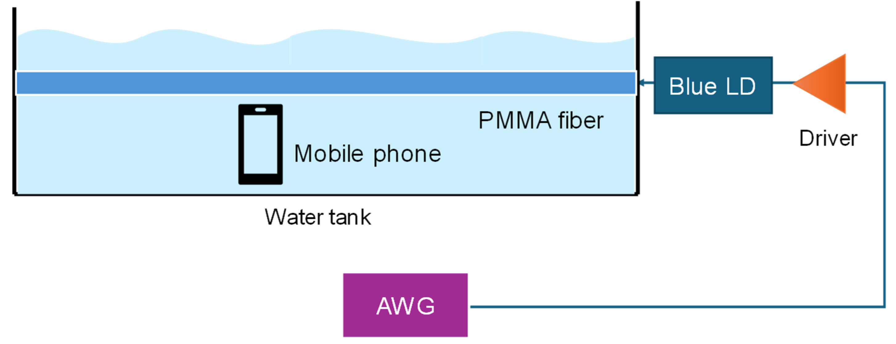
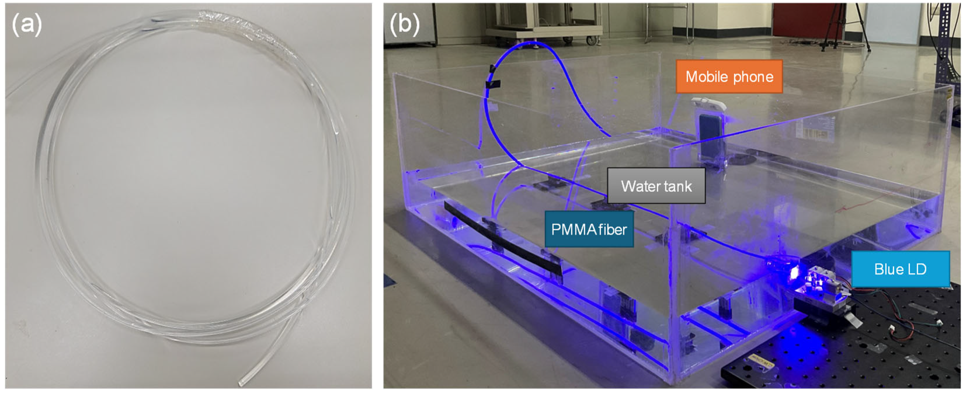
  • Underwater VLC systems reported in the studies usually employ LD or LED Txs. Here, we employ SGOF Tx, which is lightweight, flexibly bendable, and water resistant. It can also provide 360° “omni-directional” uniform light emission around its circumference.
  • Underwater VLC systems reported in the studies usually employ PD or APD Rxs. Here, we employ a CMOS image sensor-based OCC, which allows reliable and larger FOV detection.
  • In this demonstration, both SGOF Tx and the CMOS image sensor are immersed in water to achieve more accurate experimental results.
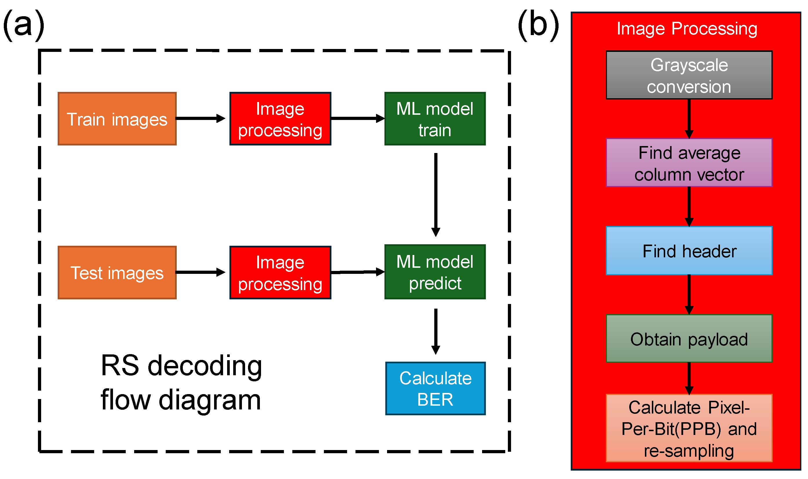
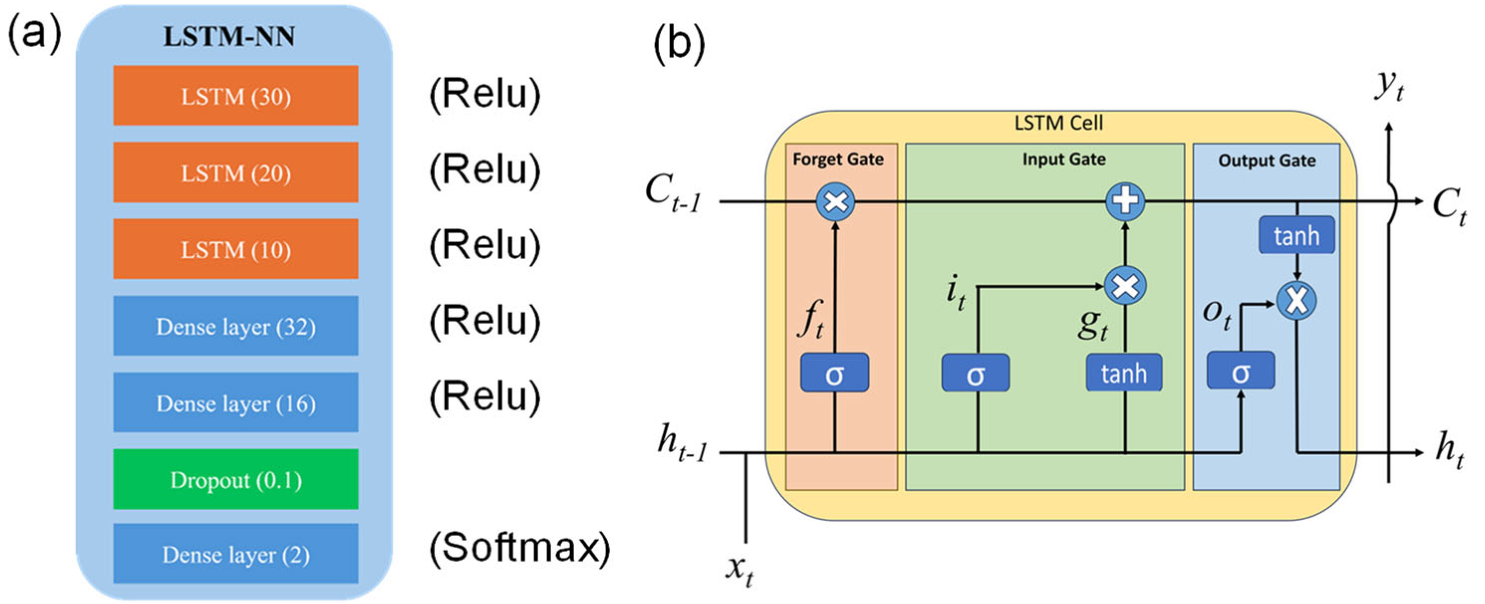
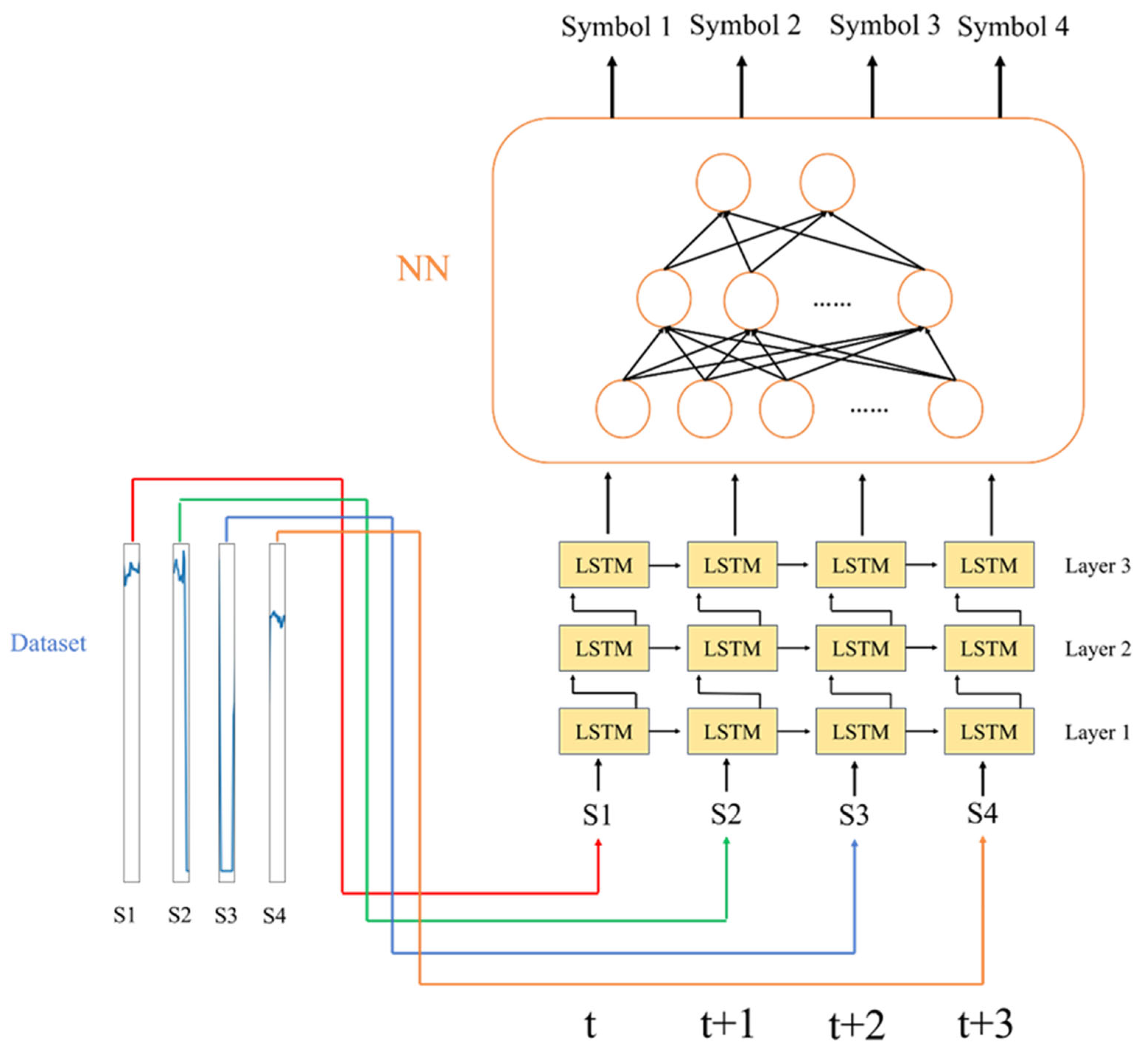
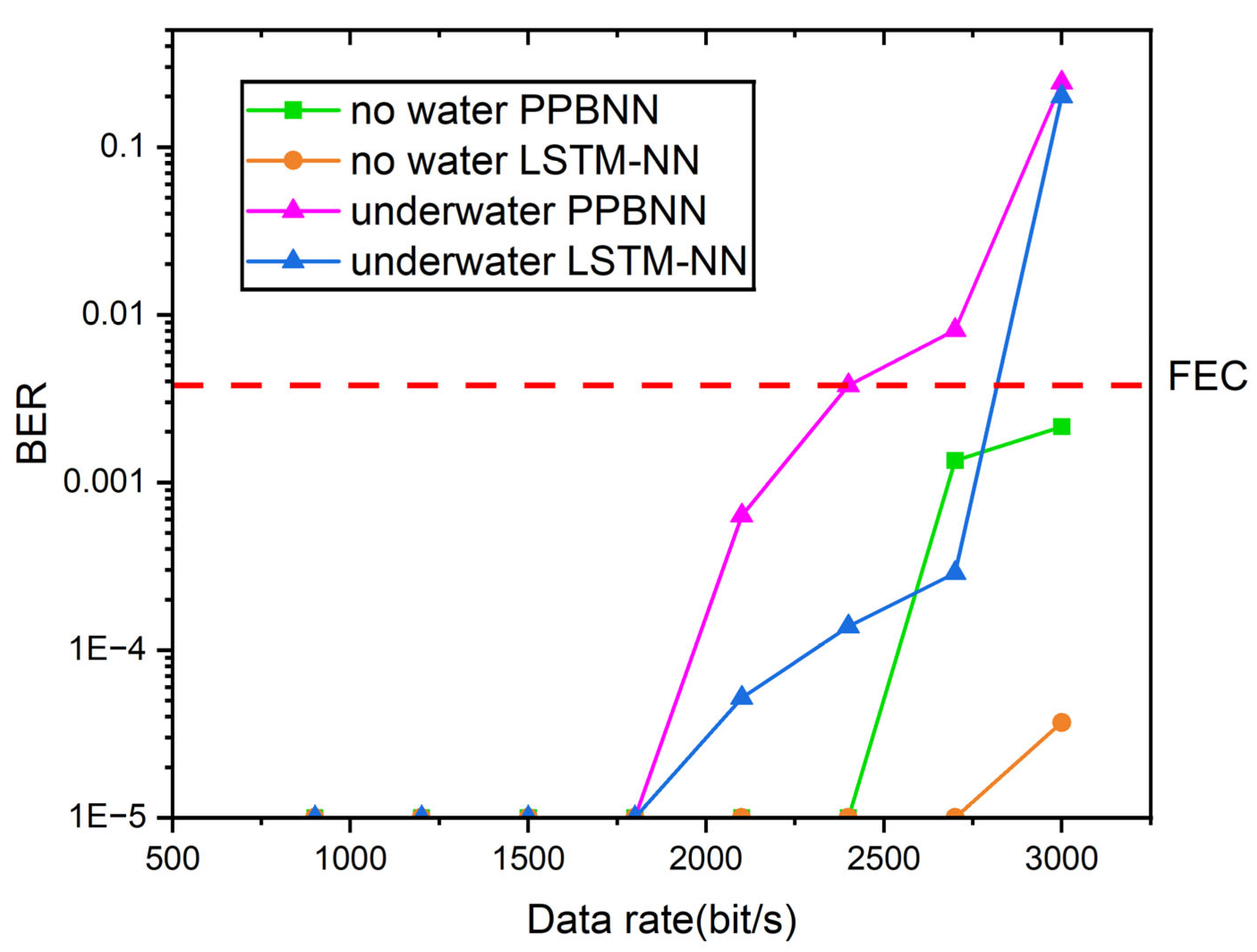
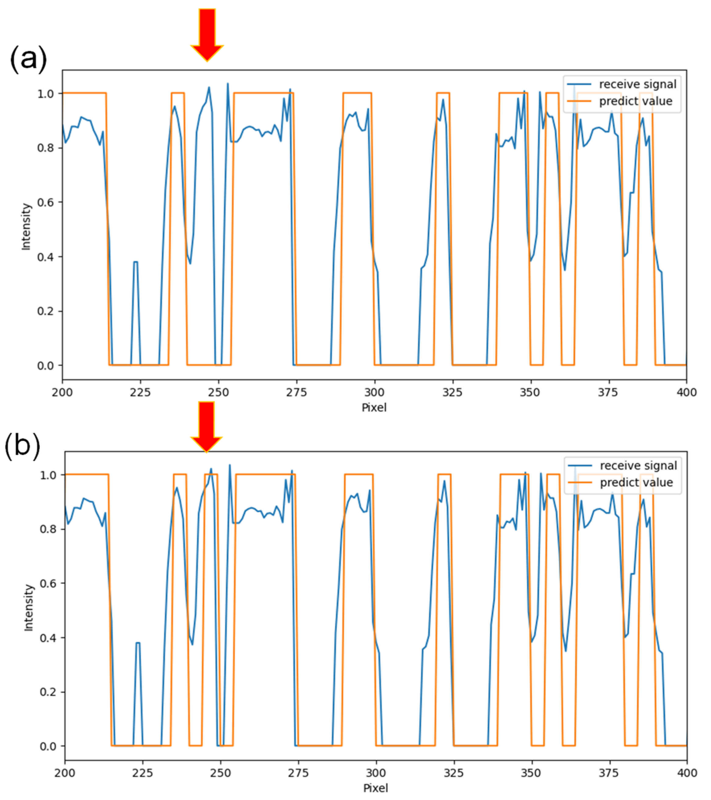
  • Here, RS decoding is realized by the proposed LSTM-NN, which has the time-memorizing characteristics to enhance the decoding of the OCC signal.
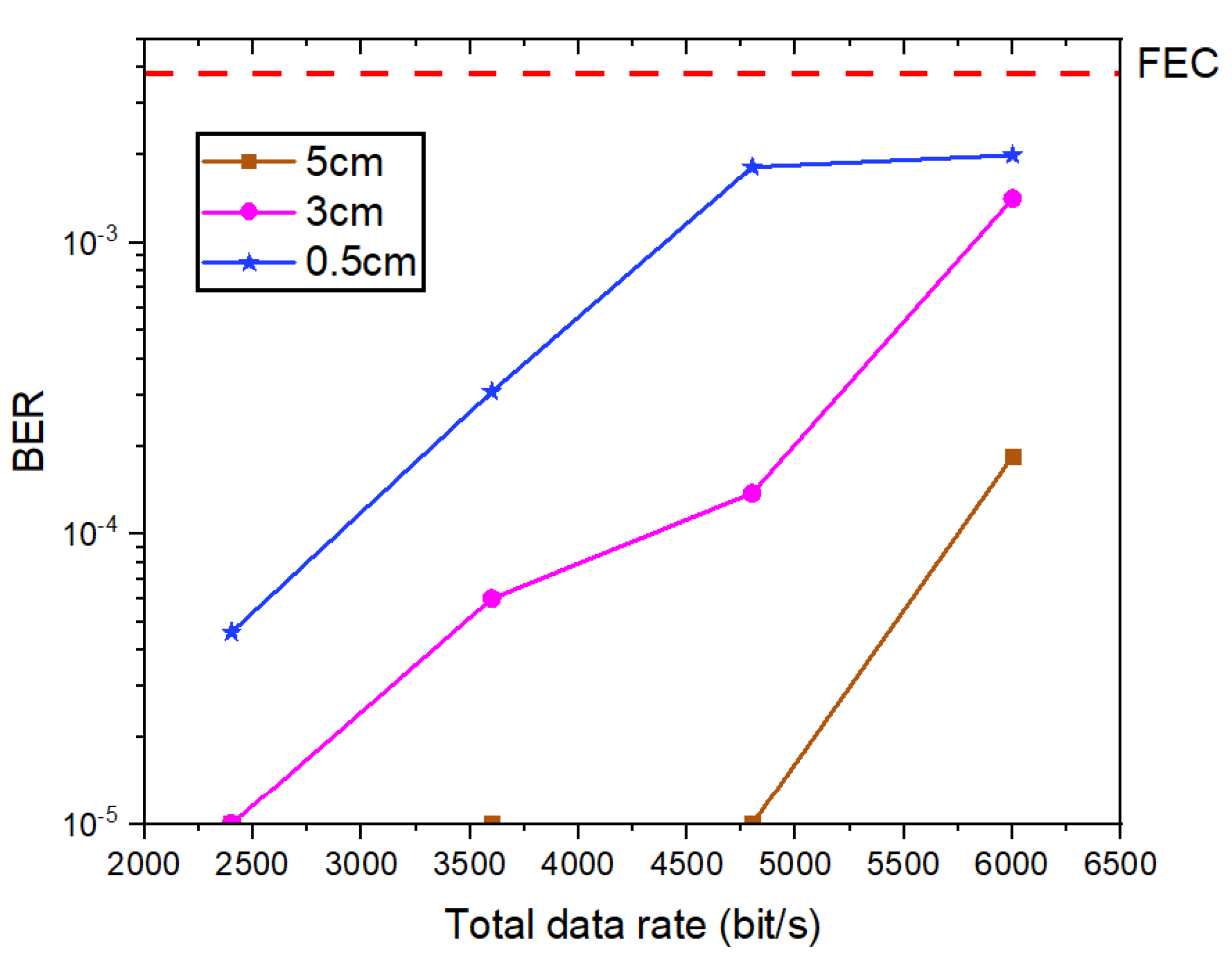
  • Parallel SGOF Txs are also studied to achieve spatial multiplexing, enhancing the total transmission capacity.

2. Experimental Setup
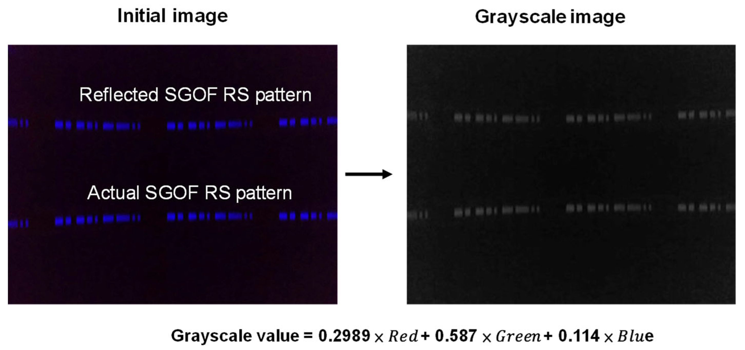
The experiment setup of the proposed RS-based UWOC system with PMMA SGOF is shown in Figure 1. The on–off keying (OOK) signal at different data rates is produced by a low-speed arbitrary waveform generator (AWG, Tektronix® AFG3252C, Beaverton, OR, USA). The AWG has a sampling rate of 2 GS/s and an analog bandwidth of 240 MHz. It is used to modulate a blue LD directly via an LD driver. The blue LD has an output optical power of 600 mW and a wavelength of 445 nm. Then, the blue OOK optical signal is launched into the PMMA SGOF, which is located inside a water tank with dimensions of 0.3 m × 0.73 m × 0.88 m. The PMMA SGOF has a diameter of 3 mm and a length of 2 m. The OCC Rx is a mobile phone (ASUS® Zenfone3, Taiwan, China) with a CMOS camera with a 30 fps frame rate and a 1920 × 1440 pixel resolution. We select a shutter speed of 1/10,000 s and an ISO of 1600 in the experiment. As this mobile phone is not water resistant, it is put inside a waterproof transparent plastic bag, and then the Rx is placed inside the water tank. The Tx includes the PMMA SGOF and the blue LD module. The blue LD module consists of a blue LD with an output power of 600 mW and an LD driver. The driver DC voltage is 12 V, the modulation mode is analog, and the maximum modulation frequency is 10 kHz. An optical collimator is installed in front of the LD to produce the optical beam divergence < 3 mrad.
In order to increase the applicability of our proposed UWOCC system, we use off-the-shelf components and devices. Hence, a typical mobile-phone-embedded CMOS image sensor can be used. The SGOF is also an off-the-shelf product. There is no special requirement about the dimensions of the water tank, as long as the SGOF and the mobile phone can be immersed for the experiment. The use of a 445 nm wavelength blue LD is because it has low attenuation underwater, as shown in [18].
Here, the PMMA SGOF is utilized as the optical Tx. It is robust against bending and stretching. It is mainly used for signage lighting, such as advertising light boxes, swimming pools, tunnels, etc. Table 1 shows the parameters of the SGOF used in the experiment. Figure 2a,b show, respectively, the photographs of the PMMA SGOF and the proof-of-concept experiment, illustrating the PMMA SGOF emitting blue light homogeneously around its circumference. It can act as a wide 360° large FOV “omni-directional optical Tx”. This large FOV can fascinate the optical detection in turbulent water environments. In the proof-of-concept demonstration, the distance between the mobile phone and the PMMA SGOF is about 20 cm.
The OCC Rx is a CMOS Image Sensor (Sony® IMX298, Tokyo, Japan) embedded in a mobile phone (ASUS® Zenfone3). Table 2 shows the parameters of the CMOS image sensor used in the experiment.
In the RS-based OCC system reported in this work, when the transmission distance between the SGOF and the camera increases, the occupied area of the SGOF image captured in the CMOS image sensor becomes smaller. As the RS is produced at the CMOS camera, the RS column pixel width is unchanged when the transmission distance increases. Hence, when the transmission distance increases, a complete OCC packet cannot be observed in an image frame, as illustrated in [32], and the BER measurement cannot be performed. In addition to the transmission distance limitation, UWOCC performance could also be affected by water clarity and water turbulence. This is because dirty water will block the light and reduce the received signal-to-noise ratio (SNR), while wavy water could distort the received RS pattern and increase the BER. We believe that it could be employed in real underwater conditions if the received SNR is enough.

3. AI/ML Algorithm

We now discuss the RS decoding algorithm. Figure 3a shows the RS pattern decoding flow diagram for the PMMA SGOF-based UWOCC system. First, different image frames obtained in the UWOCC system are divided into train images and test images, respectively. Then, these image frames are launched into the “image processing module”, as shown in Figure 3b. This module is used in both the training and testing processes. We will discuss the “image processing module” in detail later in this section. Then, the processed images will be input into the ML models for training and testing, respectively. It is worth noting that the images are different for the model training and testing. Finally, BER will be calculated based on ML model prediction.
We will now discuss the “image processing module”. The first step is the grayscale conversion. Because each pixel obtained in the CMOS image sensor consists of three colors, red, green, and blue, the images will be converted to grayscale format based on the equation grayscale value = 0.2989 × Red + 0.587 × Green + 0.114 × Blue. As shown in Figure 4, grayscale 0 means dark and 255 means bright. We can observe two RS patterns in Figure 4, in which the lower one is the actual SGOF fiber image and the upper one is generated by the reflection of the water tank. We only need one fiber image to decode the signal. It is worth mentioning that we convert the rolling shutter pattern into grayscale values (i.e., a grayscale value of 0 means complete darkness and a grayscale value of 255 means complete brightness) to facilitate the subsequent signal processing, such as signal enhancement (i.e., enhancing the grayscale value), and thresholding (i.e., identify logic 1 or logic 0) in this work since only blue light is utilized and modulated. We believe that only extracting the blue light from the signal processing could be good enough.
The image will be turned counterclockwise 90 degrees, and the actual SGOF RS pattern will be selected. There are several columns containing signals, so these columns will be added up, as shown in Figure 5. After this process, these columns will be averaged. The new column is the average column vector, as illustrated in Figure 6. The second step in Figure 3b is to find the average column vector. Then, we can locate the two headers from the average column vector; the OCC signal between headers is the data payload. After obtaining the payload, we can perform the last step in Figure 3b, which is the pixel-per-bit (PPB) calculation and re-sampling. This process is performed to ensure that each bit contains the same number of pixels. This means that if a label of the neural network is composed of several pixels, the number of pixels is the PPB. For instance, if the payload length is 340 pixels and the input signal is 30 bits, the payload will be re-sampled to 360 pixels (i.e., it is divisible by 30), and the PPB is equal to 12. The twelve pixels are used as one label for the model.
Figure 7a,b show the proposed architecture of the LSTM-NN and the LSTM cell, respectively. The first three layers are the LSTM layers, and the operation mechanism will be described later in this section. They have LSTM cell numbers of 30, 20, and 10, respectively. They are followed by another three fully connected (FC) dense layers with neural numbers of 32, 16, and 2, respectively. The dropout layer is used before the last layer to prevent overfitting. The activation functions for the first five layers are Relu, and the last layer is Softmax. The loss function is sparse categorical cross-entropy (SCCE) and the optimizer is Adam. The learning rate, epoch, and batch size are 0.01, 200, and 30, respectively.
Figure 7b shows the LSTM cell [49] used in decoding the UWOCC system. Variables in the LSTM cell include xt, Ct−1, Ct, ht−1, ht, and yt. They are the current input, cell state memory from the last cell, cell state memory from the newly updated cell, hidden state output of the last cell, hidden state output of the current cell, and current output, respectively. σ is the sigmoid activation. There are three gates in each LSTM cell. They are the forget gate, input gate, and output gate. The forget gate can decide whether the information should be stored or erased, the input gate determines what new information is stored, and the output gate produces output based on the LSTM cell state after different operations. First, we discuss the forget gate operation as shown in Equation (1).
f t = σ ( W f [ x t , h t 1 ] + b f )
where W and b are the weight and base, respectively. The result in Equation (1) will be multiplied by the old LSTM cell state Ct−1 and added with the results from the input gate to produce the new LSTM cell state Ct, as illustrated in Equation (2).
C t = f t × C t 1 + i t × g t
Then, we discuss the input gate. Equation (2) shows the product of the two outputs from input gate it × gt, and they can be expressed in Equation (3).
i t = σ ( W i [ x t , h t 1 ] + b i ) g t = tanh ( W g [ x t , h t 1 ] + b g )
Finally, the result from the output gate can be expressed in Equation (4).
o t = σ ( W o [ x t , h t 1 ] + b o )
Then, the updated hidden cell state obtained in Equation (4) can be multiplied with the tanh function of the previous LSTM cell state, as illustrated in Equation (5).
y t = h t = o t × tanh ( C t 1 )
In the LSTM-NN, several time domain features should be extracted for training. In the experiment, the input OCC signal is divided into several groups, and the number of each group is the “PPB”. The parameter for time is “time-step”, which is equal to 4. This means that when time is equal to t, the signal from t − 4 to t − 1 will be considered, as illustrated in Figure 8.
Finally, BER measurement of the RS-based UWOC system with PMMA SGOF is performed. Here, in this proof-of-concept experiment, the LSTM-NN will be compared with the PPB-NN [40]. Additionally, the experiment of the UWOC system without water is also performed for comparison. Figure 9 shows the architecture of the PPB-NN used for the comparison. It consists of one input layer, two hidden layers, and one output layer. The activation functions are Relu and Softmax, respectively, as shown in Figure 9. It is similar to a typical fully connected deep neural network (DNN) but with a different input layer. Here, the PPB-NN input layer should match the pixel per bit in the experiment. If the pixel per bit is not a round number, it should be rounded off to the higher round number. For example, if the PPB is 4.1, it will be rounded off to 5; then, the number of neurons in the input layer is 5.

4. Results and Discussion

Figure 10 shows the BER measurements of the RS-based UWOC system with PMMA SGOF using the proposed LSTM-NN model and PPB-NN model in the underwater and without water (i.e., air) cases. It can be observed that the BER curves with the water case and without the water case are similar at low data rates < 1.8 kbit/s. Without the water case, all of the BER curves can satisfy the pre-FEC threshold (i.e., BER ≤ 3.8 × 10⁻³), and the data rate can achieve 3 kbit/s. In the underwater case, we can observe that the water significantly affects the OCC signal detection by the image sensor; hence, choosing a suitable model is important. When PPB-NN is used, the data rate > 2.1 kbit/s cannot satisfy the pre-FEC threshold. However, when the LSTM-NN is used, a data rate of 2.7 kbit/s can be achieved, satisfying the FEC threshold. In the experiment, tap water is used, and it is at room temperature. As shown in Figure 2b, the water is stored in a water tank, and the experiment is performed at the laboratory in the afternoon. We believe that as long as the water density variation will not distort the rolling shutter pattern, UWOCC performance will be unaffected.
In this experiment, because we need to handle the problem of signal classification, we use the sparse categorical cross-entropy function as the loss function. We can use the loss function based on the training data and obtain the corresponding loss value in each epoch. The smaller the loss value, the better the model prediction. Here, for every 300 image frames, the first 30 image frames are used for training, and the rest of the 270 image frames are used for testing. Of the thirty training image frames, six of them will be used for validation; hence, the validation rate is 0.2. As shown in Figure 11, when the number of training times increases, the loss value decreases and starts to converge after 75 epochs. Because the loss value decreases as the number of training times increases, and it completely converges after 200 epochs with a loss value of <10−3, the proposed LSTM-NN model has shown good accuracy. The learning rate, epoch, and batch size are 0.01, 200, and 30, respectively.
Here, we also investigate the error occurring using the PPB-NN model and the LSTM-NN mode, as illustrated in Figure 12a,b, respectively. The received data pattern and the predicted data pattern are also illustrated. At about the 250th pixel in the received signal, there are several higher-intensity peaks. When applying the PPB-NN model, the predicted result is incorrect, as illustrated in Figure 12a. When applying the LSTM-NN model, the correct result can be observed, showing that the LSTM-NN model has better accuracy than the PPB-NN in underwater conditions.
As the PMMA SGOF is thin and only occupies a few pixels in the RS scanning direction, we also study the applicability of performing spatial multiplexing for enhancing the transmission capacity. Here, two fibers are put side by side at different separation distances, and we study the crosstalk produced. Due to the limited AWG and SGOF available in the laboratory, we can only experimentally evaluate two fibers carrying different random OOK data. Figure 13 shows the BER measurements at different data rates and different fiber separations of 0.5 cm, 3 cm, and 5 cm, respectively. The decoding algorithm is based on the LSTM-NN model described in Section 3. In order to get rid of the fiber reflection by the water tank, they are studied in the air condition. We can observe that the crosstalk is negligible when the fiber separation is at 5 cm. By decreasing the fiber separation, the crosstalk between the two fibers increases. This is because when the fiber separation decreases, the occupied pixels in the RS pattern also decrease, as illustrated in Table 3. When the fiber separation is 0.5 cm, a total data rate of 6 kbit/s (i.e., two fibers case), satisfying the pre-FEC BER of 3.8 × 10⁻³, can be achieved. At this fiber separation of 0.5 cm, the occupied number of pixels between the two fibers is ~20 pixels. As our CMOS image sensor has a 1920 × 1440 pixel resolution, it can be estimated that 96 fibers can be captured in the image sensor. Hence, an aggregated data rate > 200 kbit/s (i.e., 96 fibers × 3 kbit/s) could be possible.

5. Conclusions

In this work, we presented and demonstrated a RS-based UWOCC system utilizing an LSTM-NN with SGOF. In order to enhance the applicability of OCC systems, both the Tx and Rx sides should have a wide FOV. Recently, wide FOV optical Txs based on SGOF were proposed. They can provide 360° uniform light emission around the fiber circumference. This means that SGOF can act as an “omni-directional optical antenna”. In the literature, SGOF was installed in a flying UAV to provide OCC transmission. Furthermore, SGOF was demonstrated to support multiple movable Rxs to obtain data signals along the fiber. SGOF is lightweight and flexibly bendable. Most importantly, SGOF is water resistant; hence, it can be installed in underwater environments. As SGOF Tx is lightweight, flexibly bendable, and water resistant, one potential application is that it can be easily installed on the surface of underwater AUVs for transmitting sensing or surveillance information to other nearby AUVs or divers equipped with CMOS image sensors for signal receiving. The proposed LSTM-NN has the time-memorizing characteristics to enhance OCC signal decoding. The proposed LSTM-NN is also compared with other decoding methods in the literature, such as the PPB-NN. The experimental results demonstrated that the proposed LSTM-NN outperforms the PPB-NN in the UWOCC system. A data rate of 2.7 kbit/s can be achieved in UWOCC, satisfying the pre-FEC condition (i.e., BER ≤ 3.8 × 10⁻³). We also studied that at a fiber separation of 0.5 cm, the occupied number of pixels between the two fibers was ~20 pixels. When using a CMOS image sensor with a 1920 × 1440 pixel resolution, it can be estimated that 96 fibers can be captured in the image sensor. Hence, an aggregated data rate > 200 kbit/s (i.e., 96 fibers × 3 kbit/s) could be possible.

Author Contributions

Data curation, J.-F.L., Y.-H.C. and Y.-J.C.; funding acquisition, C.-W.C.; investigation, J.-F.L. and Y.-H.C.; writing—original draft, J.-F.L.; writing—review and editing, J.-F.L. and C.-W.C. All authors have read and agreed to the published version of the manuscript.

Funding

This paper was supported by the National Science and Technology Council, Taiwan, under Grant NSTC-112-2221-E-A49-102-MY3, NSTC-113-2221-E-A49-055-MY3, NSTC-113-2218-E-011-009, and NSTC-113-2640-E-A49-006.

Institutional Review Board Statement

Not applicable.

Informed Consent Statement

Not applicable.

Data Availability Statement

The data presented in this study are available on request from the corresponding author. The data are not publicly available due to privacy.

Conflicts of Interest

The authors declare no conflicts of interest.

References

  1. Komine, T.; Nakagawa, M. Fundamental analysis for visible-light communication system using LED lights. IEEE Trans. Consum. Electron. 2004, 50, 100–107. [Google Scholar] [CrossRef]
  2. O’Brien, D.C.; Zeng, L.; Le-Minh, H.; Faulkner, G.; Walewski, J.W.; Randel, S. Visible light communications: Challenges and possibilities. In Proceedings of the 2008 IEEE 19th International Symposium on Personal, Indoor and Mobile Radio Communications, Cannes, France, 15–18 September 2008; pp. 1–5. [Google Scholar]
  3. Chow, C.W.; Yeh, C.H.; Liu, Y.; Liu, Y.F. Digital signal processing for light emitting diode based visible light communication. IEEE Photon. Soc. Newslett. 2012, 26, 9–13. [Google Scholar]
  4. Lee, C.; Shen, C.; Oubei, H.M.; Cantore, M.; Janjua, B.; Ng, T.K.; Farrell, R.M.; El-Desouki, M.M.; Speck, J.S.; Nakamura, S.; et al. 2 Gbit/s data transmission from an unfiltered laser-based phosphor-converted white lighting communication system. Opt. Exp. 2015, 23, 29779–29787. [Google Scholar] [CrossRef] [PubMed]
  5. Chi, Y.C.; Hsieh, D.H.; Tsai, C.T.; Chen, H.Y.; Kuo, H.C.; Lin, G.R. 450-nm GaN laser diode enables high-speed visible light communication with 9-Gbps QAM-OFDM. Opt. Exp. 2015, 23, 13051–13059. [Google Scholar]
  6. Huang, X.H.; Lu, H.H.; Chang, P.S.; Liu, C.X.; Lin, Y.Y.; Ko, T.; Chen, Y.T. Bidirectional white-lighting WDM VLC–UWOC converged systems. J. Light. Technol. 2021, 39, 4351–4359. [Google Scholar] [CrossRef]
  7. Haas, H.; Elmirghani, J.; White, I. Optical wireless communication. Phil. Trans. R. Soc. 2020, 378, 37820200051. [Google Scholar] [CrossRef]
  8. Serafimovski, N.; Jungnickel, V.; Jang, Y.M.; Qiang, J.L. An Overview on High Speed Optical Wireless/Light Communications. IEEE 802.11-17/0962r1. 2017. Available online: https://www.google.com.hk/url?sa=t&source=web&rct=j&opi=89978449&url=https://www.ieee802.org/802_tutorials/2017-07/11-17-0962-03-00lc-An-Overview-on-High-Speed-Optical-Wireless-Light.pdf&ved=2ahUKEwjog5Oo16CIAxV4slYBHcwSCkgQFnoECBIQAQ&usg=AOvVaw3wccs1P_LroY6R9zUmvzkC (accessed on 1 September 2024).
  9. Chow, C.W. Recent advances and future perspectives in optical wireless communication, free space optical communication and sensing for 6G. J. Light. Technol. 2024, 42, 3972–3980. [Google Scholar] [CrossRef]
  10. Haas, H.; Yin, L.; Wang, Y.; Chen, C. What is LiFi? J. Light. Technol. 2016, 34, 1533–1544. [Google Scholar] [CrossRef]
  11. Chi, N.; Zhou, Y.; Wei, Y.; Hu, F. Visible light communication in 6G: Advances, challenges, and prospects. IEEE Veh. Technol. Mag. 2020, 15, 93–102. [Google Scholar] [CrossRef]
  12. Lu, H.H.; Li, C.Y.; Lin, H.H.; Tsai, W.S.; Chu, C.A.; Chen, B.R.; Wu, C.J. An 8 m/9.6 Gbps underwater wireless optical communication system. IEEE Photon. J. 2016, 8, 7906107. [Google Scholar] [CrossRef]
  13. Chen, L.K.; Shao, Y.; Di, Y. Underwater and water-air optical wireless communication. J. Light. Technol. 2022, 40, 1440–1452. [Google Scholar] [CrossRef]
  14. Tsai, S.Y.; Chang, Y.H.; Chow, C.W. Wavy water-to-air optical camera communication system using rolling shutter image sensor and long short term memory neural network. Opt. Express 2024, 32, 6814–6822. [Google Scholar] [PubMed]
  15. Singh, H.B.; Pal, R. Submarine communications. Def. Sci. J. 1993, 43, 43–51. [Google Scholar] [CrossRef]
  16. Quazi, A.H.; Konrad, W.L. Underwater acoustic communications. IEEE Commun. Mag. 1982, 20, 24–30. [Google Scholar] [CrossRef]
  17. Akyildiz, I.F.; Pompili, D.; Melodia, T. Underwater acoustic sensor networks: Research challenges. Ad Hoc Netw. 2005, 3, 257–279. [Google Scholar] [CrossRef]
  18. Soliman, D. Augmented Microscopy: Development and Application of High-Resolution Optoacoustic and Multimodal Imaging Techniques for Label-Free Biological Observation. Ph.D. Thesis, Technische Universität München, Munich, Germany, 2016. [Google Scholar]
  19. Zhu, S.; Chen, X.; Liu, X.; Zhang, G.; Tian, P. Recent progress in and perspectives of underwater wireless optical communication. Prog. Quantum Electron. 2020, 73, 100274. [Google Scholar]
  20. Chi, N.; Shi, M. Advanced modulation formats for underwater visible light communications [Invited]. Chin. Opt. Lett. 2018, 16, 120603. [Google Scholar]
  21. Wang, F.M.; Liu, Y.F.; Shi, M.; Chen, H.; Chi, N. 3.075 Gb/s underwater visible light communication utilizing hardware pre-equalizer with multiple feature points. Opt. Eng. 2019, 58, 056117. [Google Scholar] [CrossRef]
  22. Zhou, Y.; Zhu, X.; Hu, F.; Shi, J.; Wang, F.; Zou, P.; Liu, J.; Jiang, F.; Chi, N. Common-anode LED on a Si substrate for beyond 15 Gbit/s underwater visible light communication. Photon. Res. 2019, 7, 1019–1029. [Google Scholar] [CrossRef]
  23. Hong, X.J.; Fei, C.; Zhang, G.W.; Du, J.; He, S. Discrete multitone transmission for underwater optical wireless communication system using probabilistic constellation shaping to approach channel capacity limit. Opt. Lett. 2019, 44, 558–561. [Google Scholar] [CrossRef]
  24. Tsai, W.S.; Lu, H.H.; Wu, H.W.; Su, C.W.; Huang, Y.C. A 30 Gb/s PAM4 underwater wireless laser transmission system with optical beam reducer/expander. Sci. Rep. 2019, 9, 8065. [Google Scholar] [CrossRef] [PubMed]
  25. Hu, S.; Mi, L.; Zhou, T.; Chen, W. 35.88 attenuation lengths and 3.32 bits/photon underwater optical wireless communication based on photon-counting receiver with 256-PPM. Opt. Express 2018, 26, 21685–21699. [Google Scholar] [CrossRef] [PubMed]
  26. Chen, H.L.; Chen, X.W.; Lu, J.; Liu, X.; Shi, J.; Zheng, L.; Liu, R.; Zhou, X.; Tian, P. Toward long-distance underwater wireless optical communication based on A high sensitivity single photon avalanche diode. IEEE Photon. J. 2020, 12, 7902510. [Google Scholar] [CrossRef]
  27. Su, X.; Ullah, I.; Liu, X.; Choi, D. A Review of Underwater Localization Techniques, Algorithms, and Challenges. J. Sens. 2020, 2020, 6403161. [Google Scholar] [CrossRef]
  28. Ullah, I.; Chen, J.; Su, X.; Esposito, C.; Choi, C. Localization and Detection of Targets in Underwater Wireless Sensor Using Distance and Angle Based Algorithms. IEEE Access 2019, 7, 45693–45704. [Google Scholar] [CrossRef]
  29. Danakis, C.; Afgani, M.; Povey, G.; Underwood, I.; Haas, H. Using a CMOS camera sensor for visible light communication. In Proceedings of the 2012 IEEE Globecom Workshops, Anaheim, CA, USA, 3–7 December 2012; pp. 1244–1248. [Google Scholar]
  30. Chow, C.W.; Liu, Y.; Yeh, C.H.; Chang, Y.H.; Lin, Y.S.; Hsu, K.L.; Liao, X.L.; Lin, K.H. Display light panel and rolling shutter image sensor based optical camera communication (OCC) using frame-averaging background removal and neural network. J. Light. Technol. 2021, 39, 4360–4366. [Google Scholar] [CrossRef]
  31. Roberts, R.D. Undersampled frequency shift ON-OFF keying (UFSOOK) for camera communications (CamCom). In Proceedings of the 2013 22nd Wireless and Optical Communication Conference, Chongqing, China, 16–18 May 2013. [Google Scholar]
  32. Chow, C.W.; Shiu, R.J.; Liu, Y.C.; Liu, Y.; Yeh, C.H. Non-flickering 100 m RGB visible light communication transmission based on a CMOS image sensor. Opt. Exp. 2018, 26, 7079–7084. [Google Scholar] [CrossRef]
  33. Luo, P.; Ghassemlooy, Z.; Le Minh, H.; Tang, X.; Tsai, H.M. Undersampled phase shift ON-OFF keying for camera communication. In Proceedings of the 2014 Sixth International Conference on Wireless Communications and Signal Processing (WCSP), Hefei, China, 23–25 October 2014; pp. 1–6. [Google Scholar]
  34. Tsai, T.T.; Chow, C.W.; Chang, Y.H.; Jian, Y.H.; Liu, Y.; Yeh, C.H. 130-m Image sensor based Visible Light Communication (VLC) using under-sample modulation and spatial modulation. Opt. Comm. 2022, 519, 128405. [Google Scholar] [CrossRef]
  35. Chang, Y.H.; Tsai, S.Y.; Chow, C.W.; Wang, C.C.; Tsai, D.C.; Liu, Y.; Yeh, C.H. Unmanned-aerial-vehicle based optical camera communication system using light-diffusing fiber and rolling-shutter image-sensor. Opt. Express 2023, 31, 18670–18679. [Google Scholar] [CrossRef]
  36. Komanec, M.; Yánez, C.G.; Eöllös-Jarošíková, K.; Zvánovec, S. Side-emitting fiber-based distributed receiver for visible light communication uplink. Opt. Lett. 2023, 48, 6180–6183. [Google Scholar]
  37. Teli, S.R.; Eollosova, K.; Zvanovec, S.; Ghassemlooy, Z.; Komanec, M. Optical camera communications link using an LED-coupled illuminating optical fiber. Opt. Lett. 2021, 46, 2622–2625. [Google Scholar] [CrossRef] [PubMed]
  38. Chang, Y.H.; Chow, C.W.; Lin, Y.Z.; Jian, Y.H.; Wang, C.C.; Liu, Y.; Yeh, C.H. Bi-Directional Free-Space Visible Light Communication Supporting Multiple Moveable Clients Using Light Diffusing Optical Fiber. Sensors 2023, 23, 4725. [Google Scholar] [CrossRef] [PubMed]
  39. Liu, L.; Deng, R.; Chen, L.K. 47-kbit/s RGB-LED-based optical camera communication based on 2D-CNN and XOR-based data loss compensation. Opt. Express 2019, 27, 33840–33846. [Google Scholar] [CrossRef] [PubMed]
  40. Lin, Y.S.; Chow, C.W.; Liu, Y.; Chang, Y.H.; Lin, K.H.; Wang, Y.C.; Chen, Y.Y. PAM4 rolling-shutter demodulation using a pixel-per-symbol labeling neural network for optical camera communications. Opt. Express 2021, 29, 31680–31688. [Google Scholar] [CrossRef]
  41. Peng, C.W.; Chow, C.W.; Tsai, D.C.; Liu, Y.; Yeh, C.H. Mitigation of PAM4 rolling shuttered pattern grayscale ambiguity in demodulation utilizing long short term memory neural network (LSTM-NN) in optical wireless communication systems. Opt. Comm. 2023, 532, 129260. [Google Scholar]
  42. Kim, B.W.; Lee, J.H.; Jung, S.Y. Transition-based Data Decoding for Optical Camera Communications Using a Rolling Shutter Camera. Curr. Opt. Photon. 2018, 2, 422–430. [Google Scholar]
  43. Higa, A.; Hisano, D.; Nakayama, Y. Demonstration of symbol timing synchronization for rolling shutter-based optical camera communication. Opt. Express 2024, 32, 29125–29137. [Google Scholar] [CrossRef]
  44. Liu, Y. Decoding mobile-phone image sensor rolling shutter effect for visible light communications. Opt. Eng. 2016, 55, 016103. [Google Scholar] [CrossRef]
  45. Younus, O.I.; Hassan, N.B.; Ghassemlooy, Z.; Haigh, P.A.; Zvanovec, S.; Alves, L.N.; Minh, H.L. Data Rate Enhancement in Optical Camera Communications Using an Artificial Neural Network Equaliser. IEEE Access 2020, 8, 42656–42665. [Google Scholar] [CrossRef]
  46. Kallweit, J.; Pätzel, M.; Pursche, F.; Jabban, J.; Morobeid, M.; Gries, T. An Overview on Methods for Producing Side-Emitting Polymer Optical Fibers. Textiles 2021, 1, 337–360. [Google Scholar] [CrossRef]
  47. Huang, J.; Kˇremenáková, D.; Militký, J.; Zhu, G. Evaluation of Illumination Intensity of Plastic Optical Fibres with Tio2 Particles by Laser Treatment. Autex Res. J. 2015, 15, 13–18. [Google Scholar] [CrossRef]
  48. Kokhanovsky, A.A. Light Scattering Reviews 10; Springer: Berlin/Heidelberg, Germany, 2016; ISBN 978-3-662-46761-9. [Google Scholar]
  49. Hochreiter, S.; Schmidhuber, J. Long short-term memory. Neural Comput. 1997, 9, 1735–1780. [Google Scholar] [CrossRef] [PubMed]
Figure 1. Experiment setup of the proposed RS-based UWOC system with PMMA SGOF. AWG: arbitrary waveform generator; PMMA: poly-methyl methacrylate.
Applsci 14 07840 g001
Figure 2. Photographs of the (a) PMMA SGOF and (b) proof-of-concept experiment, illustrating the PMMA SGOF emitting blue light homogeneously around its circumference.
Applsci 14 07840 g002
Figure 3. (a) RS pattern-decoding flow diagram for the PMMA SGOF-based UWOCC system. (b) The procedure of the module in the “image processing module”.
Applsci 14 07840 g003
Figure 4. Images of the RS pattern before and after the grayscale conversion.
Applsci 14 07840 g004
Figure 5. Image turned counterclockwise 90 degrees and the columns added up (indicated by the red arrows).
Applsci 14 07840 g005
Figure 6. Obtaining the average column vector and locating the two headers from the average column vector.
Applsci 14 07840 g006
Figure 7. (a) Architecture of the proposed LSTM-NN. (b) Architecture of the LSTM cell in the LSTM layer.
Applsci 14 07840 g007
Figure 8. Illustration of the LSTM-NN mechanism for the time step of four.
Applsci 14 07840 g008
Figure 9. Architecture of the PPB-NN.
Applsci 14 07840 g009
Figure 10. BER measurements of the RS-based UWOC system with PMMA SGOF using the proposed LSTM-NN model and the PPB-NN model in the underwater and no water (i.e., air) cases.
Applsci 14 07840 g010
Figure 11. Loss value against epochs during LSTM-NN training.
Applsci 14 07840 g011
Figure 12. The predicted values when using the (a) PPB-NN model and (b) LSTM-NN model. Red arrow indicates the about 250th pixel.
Applsci 14 07840 g012
Figure 13. BER measurements at different data rates and different fiber separations.
Applsci 14 07840 g013
Table 1. Parameters of the SGOF.
ParameterValue
Diameter3 mm
Density1.15 g/cm3
Length2 m
Refractive index1.39
Melting point130–140 °C
Table 2. Parameters of the CMOS image sensor.
ParameterFeature
Resolution1920 × 1440
Shutter typeRolling shutter
Optical format1/2.8″ optical format
Pixel size1.12 μm × 1.12 μm
Frame rate30 fps
Shutter speed1/10,000 s
Table 3. Occupied pixels in the RS pattern at different fiber separations.
Fiber Separation (cm)Occupied Pixel (Pixels)
0.520
3113
5184
Disclaimer/Publisher’s Note: The statements, opinions and data contained in all publications are solely those of the individual author(s) and contributor(s) and not of MDPI and/or the editor(s). MDPI and/or the editor(s) disclaim responsibility for any injury to people or property resulting from any ideas, methods, instructions or products referred to in the content.

