Article

Study on Noise-Reduction Mechanism and Structural-Parameter Optimization of Ventilated Acoustic Metamaterial Labyrinth Plate

1
School of Mechanical Engineering, Shenyang University of Technology, Shenyang 110870, China
2
School of Mechanical and Control Engineering, Baicheng Normal University, Baicheng 137000, China
3
School of Mechanical Engineering and Automation, Northeastern University, Shenyang 110819, China
4
College of Mechanical and Automotive Engineering, Ningbo University of Technology, Ningbo 315211, China
*
Author to whom correspondence should be addressed.
Appl. Sci. 2024, 14(17), 7865; https://doi.org/10.3390/app14177865
Submission received: 17 July 2024 / Revised: 22 August 2024 / Accepted: 30 August 2024 / Published: 4 September 2024
(This article belongs to the Section Acoustics and Vibrations)

Abstract

:
In many noise scenarios, it is necessary to ensure ventilation and noise suppression. In this paper, a ventilated acoustic metamaterial labyrinth plate (VAMLP), formed by an array of labyrinth cells (LCs), is presented. Each labyrinth cell contains four labyrinth waveguide units (WUs). Based on the impedance series principle, an analytical model of the WU was developed and validated by a numerical model and impedance-tube experiments to determine the sound transmission loss of the WU and the LC. The mechanism of the influence of thermo-viscous loss was quantitatively analyzed, and it was clarified that the VAMLP produced sound absorption due to thermo-viscous loss. The change law of impedance at the entrance of the waveguide was analyzed, revealing the noise-reduction mechanism of the labyrinth unit. Combining a BP network and an improved sparrow search algorithm (ISSA), a BP–ISSA optimization model is proposed to optimize the ventilation capacity of the labyrinth cells. The BP-network model can accurately predict the resonance frequency from the structural parameters to form the fitness function. The ISSA optimization model was constructed using the fitness function as the constraint of an equation. Finally, the combination of structural parameters with optimal ventilation capacity was obtained for a given noise frequency.

1. Introduction

With the improvement in requirements for environmental quality, noise as a kind of physical pollution is becoming noticeable. Traditional acoustic materials tend to obey the law of mass and are ineffective at low frequencies. Some of these materials, such as glass wool, are difficult to recycle. Recycling costs can be reduced through natural degradation, but this requires a large periodicity. Therefore, in practical applications, traditional acoustic materials are often limited. The advent of acoustic metamaterials has compensated, to some extent, for the shortcomings of conventional materials by enabling low-frequency noise attenuation through subwavelength or deep-subwavelength dimensions. In many noise scenarios, maintaining ventilation is a primary requirement to facilitate heat exchange by convection. Thus, in this paper, an acoustic metamaterial with ventilation capability is proposed for future application in noise-reduction scenarios such as industrial production plants.
At the turn of the century, the concept of metamaterials was gradually clarified [1,2,3]. Over time, metamaterials have been fully developed in optics [4,5] and electromagnetism [6,7,8]. In recent years, acoustic metamaterial technology has received widespread attention [9,10,11,12]. These metamaterials have been designed, analyzed, and optimized for different applications [13], such as ducted acoustic metamaterial mufflers [14,15], ventilated acoustic metamaterial windows [16], and acoustic metamaterial filters [17]. Among them, the study of acoustic metamaterials for ventilation is one of the current research hotspots [18,19,20]. Fusaro [21] proposed an acoustic metamaterial to enhance the natural ventilation and acoustic performance of windows. The metacage window structure reduced noise transmission by an average of 30 dB in the frequency range of 350–5000 Hz, with an opening rate of 33% compared with the whole system surface. This study demonstrates the natural ventilation potential of the metacage window. Ghaffarivardavagh [22] proposed a deep subwavelength acoustic metasurface unit as a high-performance selective muffler based on the Fano-like interference phenomenon and verified the acoustic performance experimentally. This open metamaterial design for high-performance muffling with a large degree of open area is of great practical value in the field of smart sound barriers and fan or engine noise reduction. Whereas designs based on Fano-like interference can only operate in a narrow frequency range, designing broadband sound barriers remains challenging. In this regard, Sun [23] designed a subwavelength-thickness acoustic ventilation barrier consisting of a central hollow aperture and two spiral channels with different pitches. The structure extends the effective bandwidth of the Fano-like principle. The proposed design was experimentally verified, and the results were consistent with analytical predictions and simulations. Xiao [24] proposed a vented acoustic metamaterial with resonant cavities arranged around a central air channel. The underlying mechanism of switchable narrowband sound transmission was revealed. Further, acoustic metamaterials extending to three dimensions were proposed. The results of this work may inspire more exploration of acoustic barriers and multifunctional applications, such as innovative noise reduction for building facades and logic elements for acoustic circuits. Kumar [25] proposed a subwavelength labyrinth acoustic meta-structure that exhibits superior sound absorption properties. The meta-structure achieves broadband absorption by dissipation of incident-propagating acoustic waves within the labyrinthine channel. In addition, the unique meta-structure design allows air circulation to promote natural ventilation and sound absorption. This design creates additional possibilities for architectural acoustics and noise shielding for both natural ventilation and noise reduction.
Few previous studies have provided theoretical model and optimization schemes for ventilated acoustic metamaterials. Therefore, in this paper, a ventilated acoustic metamaterial labyrinth plate (VAMLP) is proposed. An analytical model based on the impedance series principle and a numerical computational model based on thermo-viscous acoustics was developed. The accuracy of the theoretical model was verified by experiments. The influence mechanism of thermo-viscous loss was quantitatively investigated, and the reason for the sound absorption coefficient was elucidated. The change rule of impedance at the entrance of the waveguide unit (WU) was analyzed, revealing the noise-reduction mechanism of the labyrinth cell (LC). Combining the BP network and the improved sparrow search algorithm (ISSA), the BP–ISSA optimization model was developed to optimize the ventilation capacity for a given noise frequency.

2. Theory Model

2.1. Analytical Model

The VAMLP proposed in this paper is shown in Figure 1a, and consists of an array of LCs, as shown in Figure 1b; each LC contains a ventilated region with side length a and four WUs. In the WU, the labyrinth is divided into channels C1 and C2 with lengths l1 and l2, respectively. Noise attenuation at different frequencies is achieved by adjusting l1 and l2 of the four WUs while ensuring ventilation performance. It is worth noting that, in practice, the geometric parameters of the LC can be adjusted according to the specific noise conditions and spatial conditions, including the side length a of the ventilated area, the lengths of the channels l1 and l2, the width of the channels w, the number of turns of the channels, and the thickness of the labyrinth unit d.
The acoustic analytical model for the WU can be established by considering the two channels as connected in series. A backtracking procedure was employed to calculate Z2 and Z1 sequentially, where Z2 is the impedance at the beginning of channel C2 and Z1 is the impedance at the entrance of the side branch.
Considering the thermo-viscous effect of the wave and the radiative impedance resulting from the discontinuities on the waveguide surface, the surface acoustic impedance Z2 is derived as
Z 2 = Z r 2 Z c 2 cot ( k 2 l 2 ) cot ( k r t e ) + Z r 2 i Z c 2 cot ( k 2 l 2 ) i Z r 2 cot ( k r t e )
where Zr2 is the radiative impedance according to the Johnson–Champoux–Allard (JCA) theory [26,27], k2 is the number of waves in the channel C2, kr is the number of radiative waves according to the JCA theory, te is the effective thickness of the rigid wall, and Zc2 is the effective impedance taking into account the thermo-viscous effect.
In the JCA model, the near-field radiative impedance is calculated as Zr = ρrcr, where ρr and cr are the density and sound velocity associated with the radiation, and cr is calculated as [28]
c r = κ r ρ r
where κr is the bulk modulus associated with radiation and ρr and κr are calculated as
ρ r = α inf ρ 0 ϕ + σ i ω 1 + 4 i α inf 2 μ ρ 0 ω σ 2 χ 2 ϕ 2
κ r = γ P 0 / ϕ γ γ 1 1 + 8 μ i ρ 0 ω Pr χ 2 1 + i ρ 0 ω Pr χ 2 16 μ 1
where, the tortuosity αinf = 1, ρ0 is the air density, the porosity ϕ = 1, σ is the airflow resistivity [29,30,31], ω is the angular frequency, μ is the dynamic viscosity, and χ and χ2 are the viscous characteristic length and thermal characteristic length, respectively. Pr is Prandtl’s number.
Thermo-viscous losses are extremely important in generating the sound absorption coefficient. When thermo-viscous losses are considered in the model, the effective impedance in the channel is expressed as Zc = ρece [32]. kc = ω/ce, is the effective complex wave number in the channel, and ρe and ce are the effective density and the effective speed of sound, respectively, which are calculated as
ρ e = k e Z e ω , c e = ω k e
where ke and Ze are given as
k e 2 = k 0 γ γ 1 ψ h ψ ν
Z e 2 = Z 0 2 ψ ν γ γ 1 ψ h
where k0 is the wavevector, Z0 = ρ0c0 is the characteristic impedance of air, and γ is the specific heat ratio. ψh and ψν are the thermal and viscous functions, respectively, which can be obtained by calculating the following equations:
ψ i = k i m = 0 α m m 2 1 tan α m d 2 t / 2 α m d 2 t / 2 + β m m 2 1 tan β m w / 2 β m w / 2
where i = ν and h, denoting the viscous and thermal fields, respectively, and k ν 2 = i ω ρ 0 / μ and k h 2 = i ω ρ 0 C p / κ 0 , where Cp is the specific heat and κ0 is the bulk modulus. α m = k i 2 2 m / d 2 t , β m = k i 2 2 m / w , where m = m + 0.5 π .
The impedance Z1 at the entrance of the side branch can be calculated as
Z 1 = Z r 1 i Z s cot k r 1 t e + Z r 1 Z s i Z r 1 cot k r 1 t e
where Zr1 is the near-field radiative impedance at the entrance of the side branch, and kr1 is the wave number associated with the radiative impedance. Zs is the acoustic impedance of the channel in series, which was calculated as
Z s = Z c 1 i Z 2 / ϕ s cot k 1 l 1 + Z c 1 Z 2 / ϕ s i Z c 1 cot k 1 l 1
where Zc1 is the effective impedance under the influence of the thermo-viscous effect, k1 is the wave number of channel C1, and ϕs is the ratio of the cross-sectional area of channel C1 and channel C2.
This analyzed case contains two channels connected in series, and as the number of channels increases, the impedance at the entrance of the side branch can be derived as
Z n = Z c n i Z s n cot k r n l n + Z c n Z s n i Z c n k r n l n
where n denotes the n-th channel and Zsn is the acoustic impedance associated with the (n + 1)-th channel.
Based on the impedance Z1 at the entrance of the side branch, the transmission and absorption coefficients of the model can be calculated as [33,34]
τ = 1 ϕ 0 ρ 0 c 0 ϕ 0 ρ 0 c 0 + 2 Z 1
α = 4 Re Z n Z n 2 + 2 Re Z n + 1
where ϕ0 is the spatial opening ratio. The physical parameters of air in the analytical and numerical models are shown in Table 1.

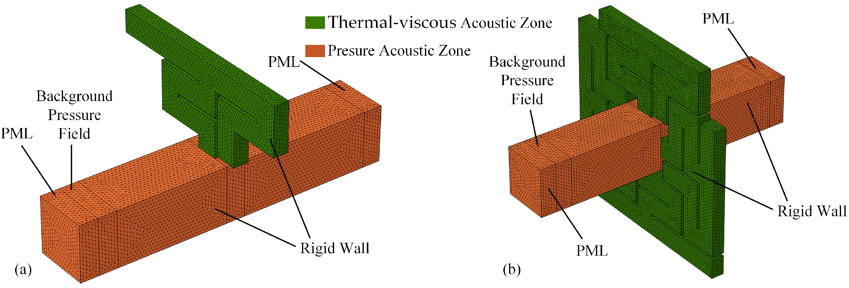
2.2. Numerical Model

Numerical computational models of the WU and the LC were established through the software COMSOL Multiphysics 6.2. The pressure acoustic interface and thermo-viscous acoustic interface were used. The numerical models of the LC and the WU have nearly identical boundary conditions, being set up, as shown in Figure 2a,b, respectively.
The goal of the elaboration is the performance of the metamaterial labyrinth itself. Therefore, the ventilated area was extended to both sides, and a perfectly matched layer (PML) was defined at both ends to absorb acoustic waves. A background pressure field was defined at the incident end with a pressure amplitude of 1 Pa. The waves were assumed to be completely reflected at the wall, so rigid wall-boundary conditions were applied. The labyrinth structure was considered the thermo-viscous losses, and the remaining part was defined as a pressure acoustic region; it contained 369,075 elements in the WU numerical model and 607,267 elements in the LC numerical model.

3. Validation and Analysis

In the process of establishing the theoretical model, some constants were defined and the high-order terms of the equations were neglected. In order to validate the model precision, the sound transmission loss (STL) comparison of the analytical models and numerical models and experiments was carried out. Three WU cases were carried out using different structural parameters, as shown in Table 2.
Impedance-tube experiments based on the transfer function method were carried out using a test system manufactured by BSWA and the experimental principle is shown in Figure 3a. The thickness of the experimental specimen was d = 12 mm, the distance between microphones m1 and m2 was s1, and the distance between microphones m3 and m4 was s2. When s1 = s2 = 0.3 m, l1 = 0.05 m, and l2 = 0.15 m, the effective test range of the impedance tube was 63–550 Hz. The experimental physical diagram is shown in Figure 3b, and the modified impedance loading Zi on the end was realized by adjusting the end cap. The LC specimen was fabricated using fused deposition modeling (FDM) technology with filament diameter of 1.75 mm, layer height of 0.1 mm, and nozzle diameter of 0.2 mm, as shown in Figure 3c. In the experiments, the STL was calculated as [35]
STL = 20 log 10 1 τ τ = T 11 + T 12 Z 0 + T 21 Z 0 + T 22 2 e j k d
where, τ is the transmission coefficient from the experiment, T is the transfer matrix calculated from the measurements, and Z0 is the characteristic impedance of air.
The comparison results are shown in Figure 4. In Case 1, for example, the results of the analytical and numerical model were in good agreement. The STL peak of the analytical model was located at 378.5 Hz, and that of the numerical model was located at 377.5 Hz, with an error of no more than 0.26%. The accuracy of the analytical model was clarified. There was a slight error between the experimental and the theoretical results. On the one hand, this was due to the processing accuracy during the manufacturing process of the specimens, and on the other hand, the fact that in the theoretical models, the rigid walls were defined, but it was difficult to realize the ideal state in the experiments. Cases 2 and 3 showed a certain frequency shift compared to case 1 due to the variation in structural parameters, but comparison of the theoretical and experimental results showed that they were in good agreement.
For case 1, the complex frequency plane associated with the transmission coefficient is calculated as log10|τ|2, as shown in Figure 5. It is worth noting that the data on the real axis are the –STL/20, and the distance between the zero and pole is positively correlated with the effective bandwidth. Considering the thermo-viscous losses, the imaginary axis coordinate of the zero point is not zero, as shown in Figure 5a, and the STL has a predictable maximum because of the thermo-viscous effect. When the effect of thermo-viscous losses is neglected, the complex plane is shown in Figure 5b. The zero point lies on the real axis, and the STL tends to be infinity. In this state, the system does not produce a sound absorption coefficient.
The sound pressure distribution in the thermo-viscous zone at the frequency corresponding to the STL peak of case 1 is shown in Figure 6a. At the end of channel C1, the sound pressure is highest, and the sound waves resonate significantly. Thus, the length l1 of channel C1 has a greater effect on the peak frequency. The sound pressure level (SPL) distribution in the pressure acoustic zone is shown in Figure 6b, with the incoming port of the sound wave on the left side and the outgoing port on the right side, and the SPL shows significant attenuation after the sound wave passes through the entrance of the channel. The maximum sound pressure level occurs within the WU, and it is clear that there is a resonance. The radiated field at the entrance of the side branch suppresses the wave propagation and achieves noise blocking.
As shown in Figure 2b, the four WUs are configured as an LC with different resonant frequencies achieved by adjusting the length l2 of channel C2, whose STL is shown in Figure 7. Without considering thermo-viscous losses, the maximum value of STL tends to infinity, which corresponds to Figure 5b when the minimum value of the transmission coefficient tends to 0. In practice, the thermo-viscous effect cannot be neglected, especially when the waveguide cell geometry is sufficiently small. Considering the thermo-viscous losses, the STL peak and resonance frequencies decrease, which is favorable for low-frequency noise suppression. At the same time, the valleys are increased. In this case, the valleys are all greater than 10 dB. The comparison of the experimental results with the numerical calculation results provides an excellent agreement and verifies the accuracy of the numerical calculation model.
To further investigate the mechanism of thermo-viscous loss action and the noise-reduction principle of the cell, the impedance at the entrance of the waveguide cell was extracted, as shown in Figure 8. In Figure 8a, the effect of thermo-viscous loss is neglected, and the resistance and reactance are close to 0 at a specific frequency, and the corresponding |Zn| tends to 0. A perfect impedance matching is realized in this state, and the wave is guided into the channel to resonate. When thermo-viscous loss is considered, the impedance is shown in Figure 8b, where the impedance is still close to 0 at specific frequencies. However, the resistance is significantly higher, caused by thermo-viscous waves. Correspondingly, the minimum value of |Zn| is greater than 0 while generating a sound absorption coefficient. As shown in Figure 9, the transmission coefficient τ, the absorption coefficient α, and the reflection coefficient r exhibit significant variations at specific frequencies. As a ventilated acoustic material, the transmission coefficient is a direct variable for evaluating the effectiveness of noise reduction, which in this case can be minimized to less than 0.1. In real noise environments, 0.5 is usually the expected value. With structural adjustments, the unit can tend to achieve noise attenuation at a majority of low frequencies.

4. Optimizations for Structural Parameters

4.1. Objective Function and Constraints

In practical applications, the noise main frequency fs should be considered first and used as an equation constraint for design. The structural parameters are targeted to be designed according to the resonance frequency fs, and the mapping relationship between the structural parameters and fs is completed by the BP network, which is fs = gBP (l1, l2, a). In this optimization case, the fs is kept the same as that of the analytical case, which is 378.5 Hz.
The ventilation capacity of the acoustic metamaterial labyrinth flat plate proposed in this paper is often the priority to be considered. It can be intuitively seen that the ventilation capacity Ω is directly related to the parameters l1, l2, and a. To optimize the ventilation capacity, l1 and l2 should be small enough, while the parameter a should be large enough. Thus the optimized objective function Ω is defined as Ω = (l1 + l2)/a. The convergence speed of the algorithm and the generation of optimal solutions are directly affected by the initial population. A randomly generated initial population can easily lead to falling into a local optimum. To avoid the algorithm’s population diversity decreasing in subsequent iterations, and to improve the quality of the initial solution, the range of optimization objectives should be limited, as shown in Table 3. Thus, the geometric parameter optimization problem with inequality constraints and equational constraints can be expressed as
min   Ω l 1 , l 2 , a s . t .   l b 1 l 1 u b 1                 l b 2 l 2 u b 2                 l b 3 a u b 3           f s = 378.5 Hz
According to the parametric constraints, the relationship between the resonant frequency and l1, and l2 is obtained, as shown in Figure 10a when a = 20 mm. The resonant frequency tends to decrease with increasing parameters l1 and l2, and the effect of l1 is greater in the set parameter range. The variation in ventilation capacity Ω with l1 and l2 is shown in Figure 10b, and the value of Ω increases as l1 and l2 increase.

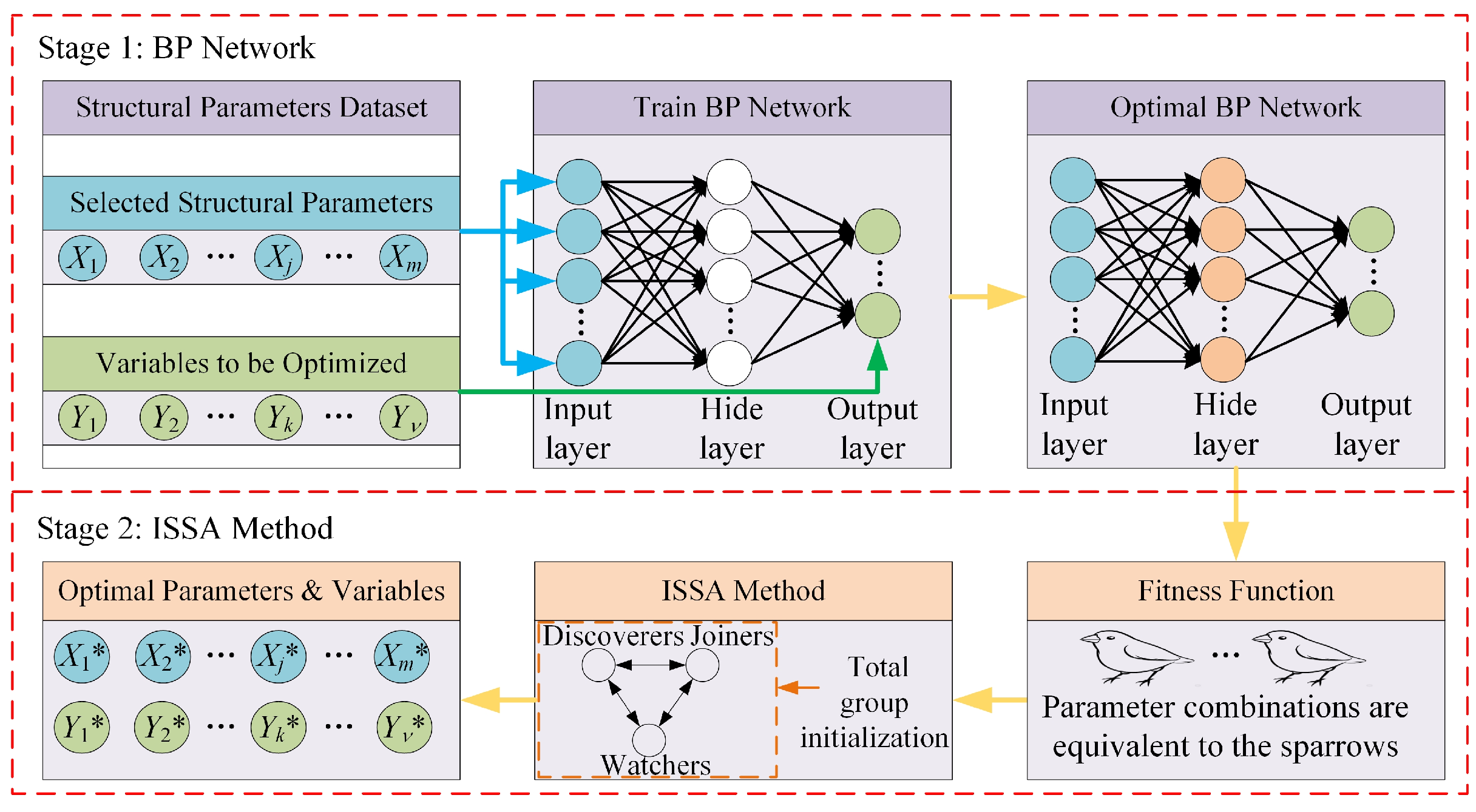
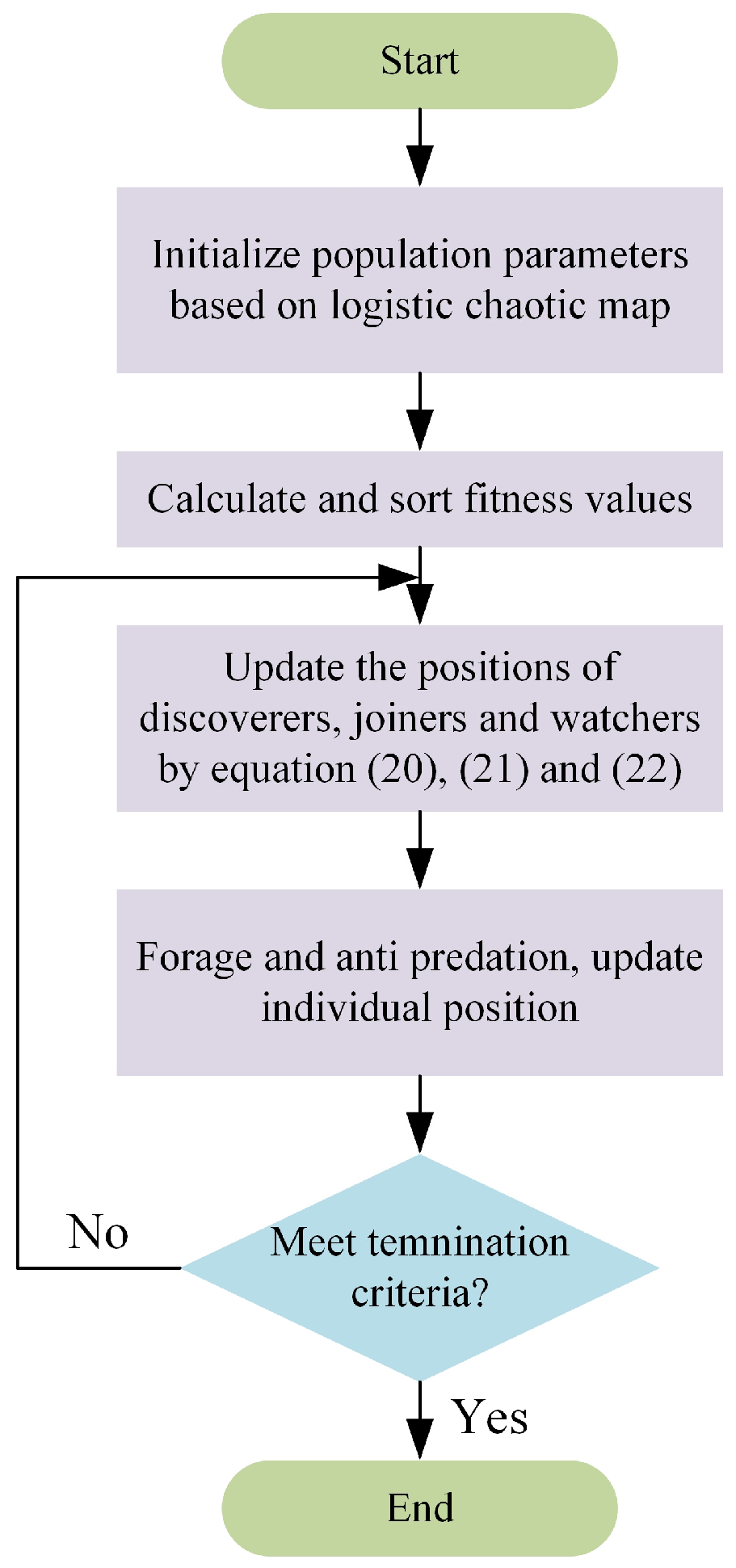
4.2. Method and Process

A complex nonlinear relationship exists between the resonance frequency fs and the structural parameters. The BP-network model is more advantageous in expressing the nonlinear relationship than the orthogonal experiment and the response surface method. In the first stage, in obtaining the fitness function of the structural parameters concerning the resonance frequency fs, the BP neural network method containing 10 hidden layers is employed. The dataset used for the BP network was obtained from the analytical model with a total of 3000 samples, of which 80% were used for training, 10% for validation, and the rest for testing. The overall optimization framework is shown in Figure 11, where the fitness function of the BP neural network output is set as an equation constraint in the second stage of the improved sparrow search algorithm (ISSA). The ISSA, which has good global search and local exploitation capabilities, is an algorithm that improves on SSA by introducing logistic chaotic mapping to avoid oscillating near the global optimal solution during the iteration process [36,37].
As a population optimization algorithm inspired by the foraging and anti-predation behaviors of sparrows, sparrows are classified into discoverers, joiners, and watchers. The calculation process is shown in Figure 12. The discoverer sparrows are responsible for finding food for the entire population and providing directions to joiner sparrows for food. The watchers are responsible for monitoring the foraging area to avoid predation. When the optimization procedure starts, logistic chaotic mapping is introduced to improve the initial population diversity and algorithm stability, which is denoted as [38]
μ = β μ 0 1 μ 0
where β 0 ,   4 and μ 0 0 ,   1 . The closer the value of β is to 4, the more uniform the distribution of values of μ is, and when β = 4, the system is in a completely chaotic state.
The initialized individual values associated with sparrow locations are calculated as [39,40]
x * , j = μ u b j l b j + l b j
Individual values are constantly updated during the optimization process. The population can be represented as a data collection, assuming the number of sparrows in the population is n, and the population dimension is m. The population is expressed as
X = x 1 , 1 x 1 , 2 x 1 , m x 2 , 1 x 2 , 2 x 2 , m x n , 1 x n , 2 x n , m
The fitness values for all sparrows can be expressed as
F X = f X 1 , 1 X 1 , 2 X 1 , m f X 2 , 1 X 2 , 2 X 2 , m f X n , 1 X n , 2 X n , m
where f is the fitness function.
In the population search process, the goals of discoverers are used as the optimization goals. The discoverers are given more food to improve search ability and range, and the position is transformed as follows:
x i , m t + 1 = x i , m t exp i δ T   ,           R 2 < S T x i , m t + Q   ,                                   R 2 S T      
where t is the current number of iterations, T is the maximum number of iterations, and δ is a random value between 0 and 1. Q is a random number obeying a normal distribution.
By behavioral guidelines of sparrows, the location update description for joiners is as follows:
x i , m t + 1 = Q exp x w m t x i , m t i 2   ,                           i > 0.5 n x b m t + 1 + x i , m t x b m t + 1 A + L ,             i 0.5 n
where, x w m t is the worst position and b m t + 1 is the optimal position currently occupied by the finder. A+ = AT(AAT)−1 and A is a 1 × m matrix with each element randomly assigned a value of 1 or −1. When i > 0.5n, it indicates that the i-th joiner did not obtain food, has a low fitness value, and needs to fly elsewhere to forage. Otherwise, it indicates that the i-th joiner will forage near the optimal position.
Sparrows are randomly selected as watchers in the population, which is typically 10–20% of the population, and the position of the watchers is updated as follows:
x i , m t = x b m t + χ x i , m t x b m t ,                                 f i f g x b e s t t + K x i , m t x w m t f i f w + e ,               f i = f g
where K is a random number between −1 and 1. χ is a normally distributed random number with variance 1 and mean 0, e is a minimal real value, fi is the i-th sparrow fitness value, fg is the optimal fitness value, and fw is the worst fitness value.

4.3. Optimization Results

BP network prediction accuracy is analyzed in Figure 13. The model regression state is shown in Figure 13a. One hundred process parameter combinations were randomly selected in the test set to compare with the actual value. The result showed that the prediction model regression was excellent, and the R2 value was calculated as 0.9998. As shown in Figure 13b, the error analysis was performed on the training set, validation set, and test set, and the error obeyed a normal distribution with minimal values, which satisfied the prediction requirements.
The ISSA optimization results corresponded to structural parameters of l1* = 213.59 mm, l2* = 42 mm, and a* = 31.8 mm, which were enlarged to increase the ventilation efficiency compared with the original structural parameters. The transmission coefficient was obtained by solving the analytical model with optimized structural parameters, as shown in Figure 14a. Due to the constraints of Equation (15), in the optimized model, the resonant frequency was 378.9 Hz, which was highly consistent with the constraint of 378.5 Hz. The increase in ventilation area raised the transmission coefficient by a minor amount, which was an adverse effect, but in practice, the effect is negligible. The WU was redesigned according to the optimized structural parameters. After the numerical model, the SPL distribution is shown in Figure 14c. It maintained a satisfactory noise-reduction performance while increasing the ventilation efficiency compared with the original WU shown in Figure 14b. The optimization results show that the optimization model of BP–ISSA can precisely optimize the structural parameters. It means that in practical applications, after clarifying the noise frequency, the WU structure can be targeted to be formed for noise suppression and to maximize ventilation and heat exchange.

5. Conclusions

In this paper, a ventilated labyrinth acoustic metamaterial plate is proposed. The corresponding analytical and numerical calculation models are established, and the validity of the model is verified through experiments. At the same time, the influence mechanism of thermo-viscous losses and the impedance-change rule at the entrance of the LC is revealed, and its noise-reduction mechanism is elaborated. By constructing the BP–ISSA optimization model, the ventilation capacity of the WU at a specific frequency is optimized. The main conclusions are as follows:
(1)
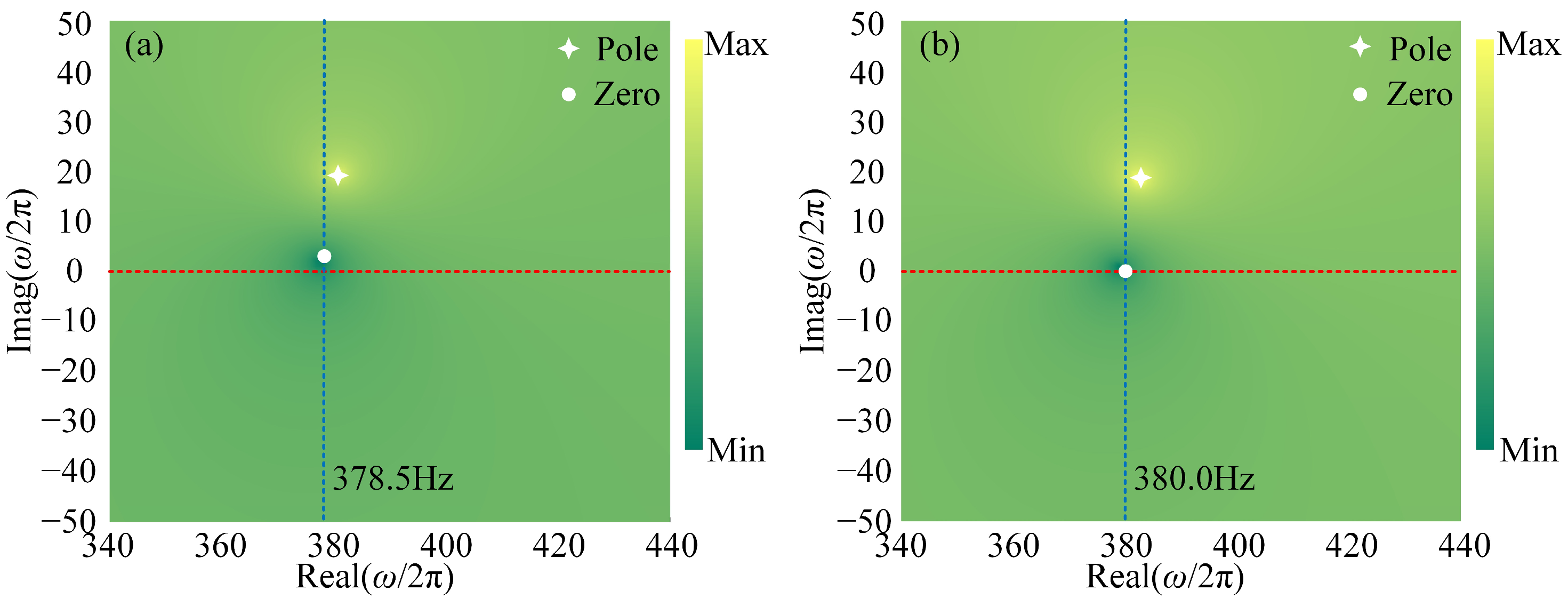
The STL and complex frequency planes of the WU were obtained by solving an analytical model based on the impedance series principle and a numerical computational model. The results show that the thermo-viscous losses caused the structure to generate a frequency shift and a reduction in the resonance frequency. At the same time, the maximum value of the STL was changed from an infinite value to a predictable value. Meanwhile, the thermo-viscous loss was responsible for the sound absorption coefficient.
(2)
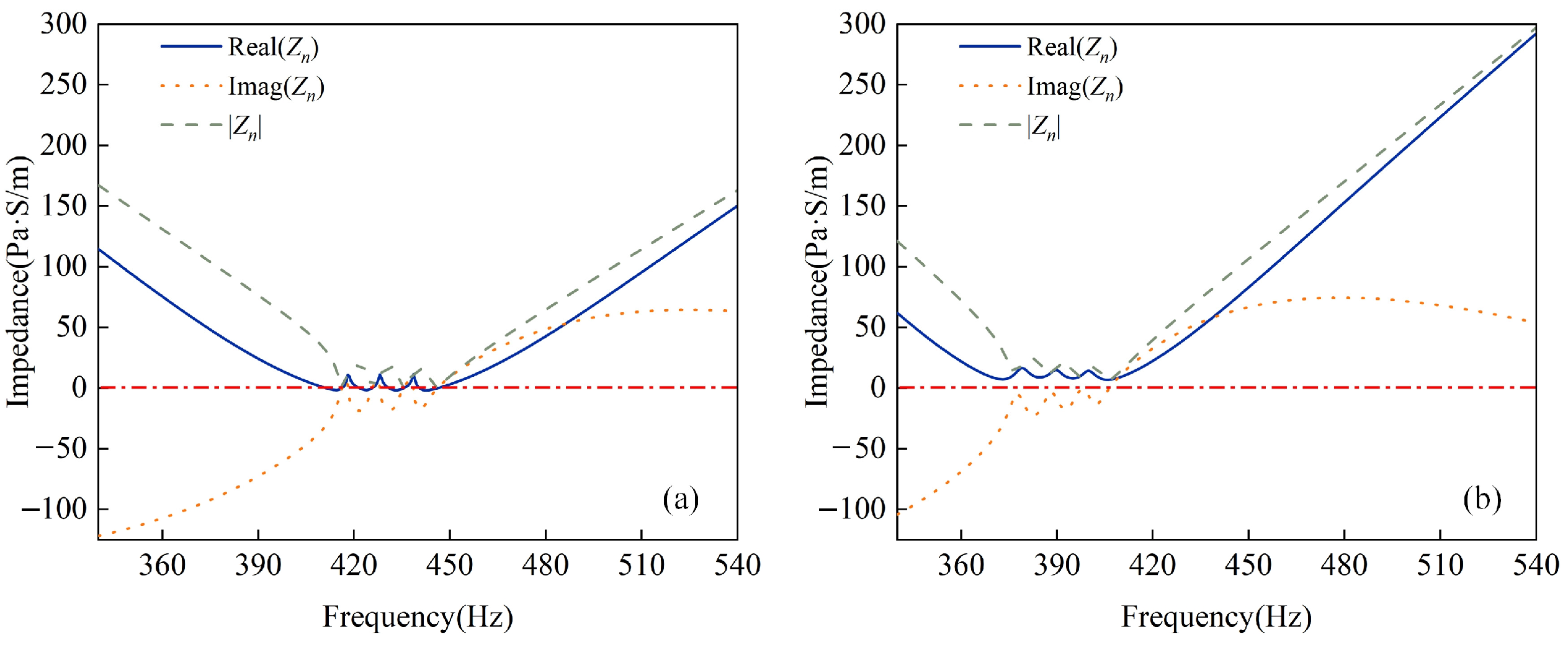
By calculating the impedance at the entrance of the waveguide cell, it is found that the impedance was perfectly matched when the labyrinth cell was in resonance mode. When thermo-viscous losses were introduced, the impedance matching state was affected and presented an imperfect match.
(3)
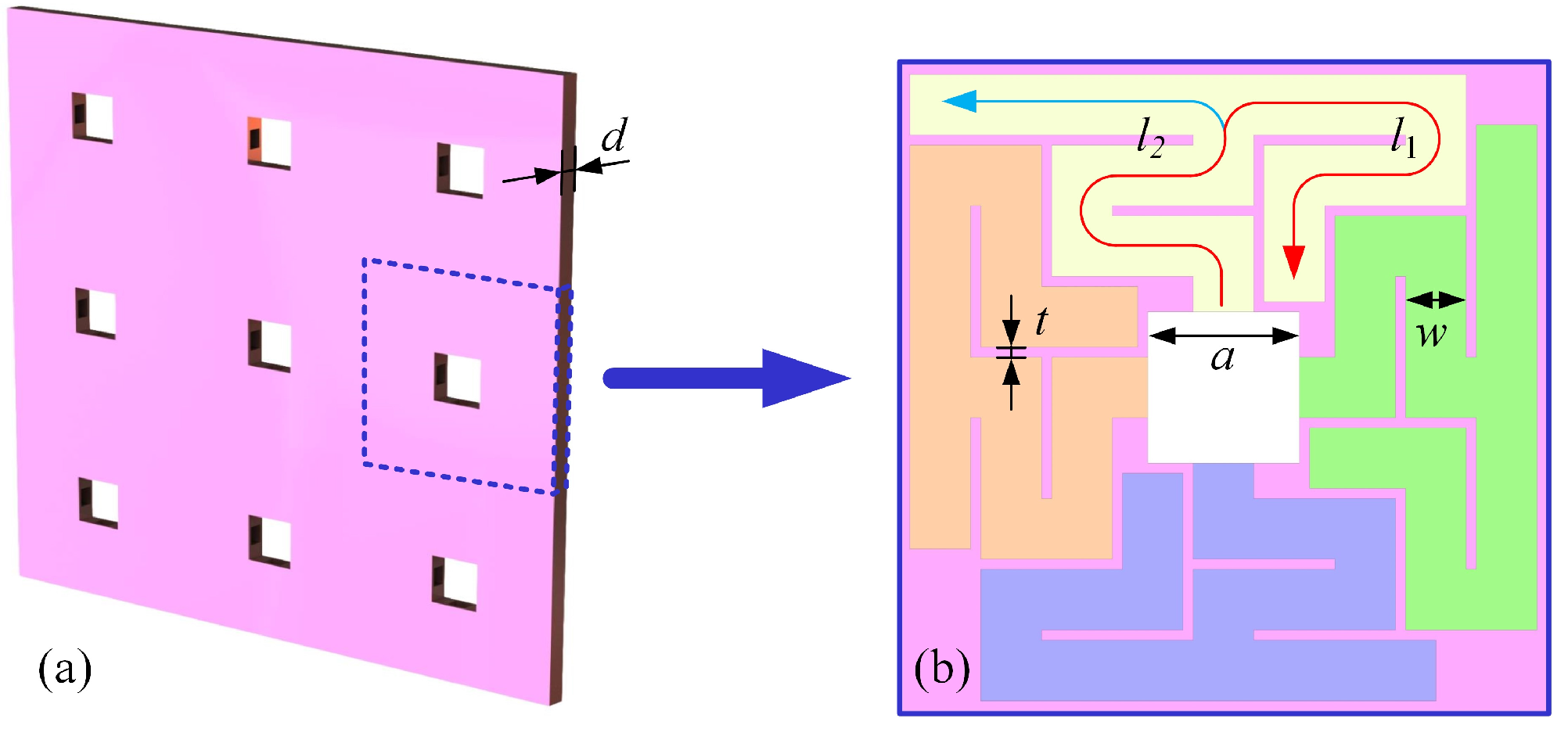
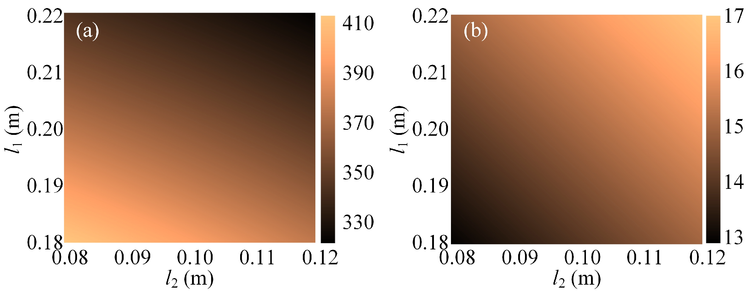
When the actual noise frequency was 378.5 Hz, the optimized structural parameters were l1* = 213.59 mm, l2* = 42 mm, and a* = 31.8 mm, with a resonance frequency of 378.9 Hz. It was verified that the structural parameter combinations could be effectively optimized through the BP–ISSA optimization model to improve the ventilation capacity of the LC.

Author Contributions

Conceptualization, D.Z., X.S. (Xianming Sun) and W.T.; methodology, D.Z. and W.T.; software, D.Z. and X.S. (Xianming Sun); validation, D.Z., Y.S. and C.C.; formal analysis, W.T.; investigation, X.S. (Xiaoming Su) and Y.S.; resources, X.S. (Xiaoming Su) and X.S. (Xianming Sun); data curation, Y.S.; writing—original draft preparation, D.Z.; writing—review and editing, W.T. and X.S. (Xianming Sun); visualization, D.Z.; supervision, C.C.; project administration, C.C. and X.S. (Xiaoming Su); funding acquisition, C.C. and X.S. (Xiaoming Su). All authors have read and agreed to the published version of the manuscript.

Funding

This research was supported by the National Natural Science Foundation of China under Grant No. 51675350, the State Key Laboratory for Joint Open Fund under Grant No. 2022-KF-22-11, the Natural Science Foundation of Jilin Province under Grant No. YDZJ202401603ZYTS, and the Jilin Department of Education Science and Technology Research Project under Grant No. JJKH20220011KJ.

Institutional Review Board Statement

Not applicable.

Informed Consent Statement

Not applicable.

Data Availability Statement

The original contributions presented in the study are included in the article, further inquiries can be directed to the corresponding author.

Acknowledgments

The authors are grateful for the discussions with colleagues that led to the development of this study.

Conflicts of Interest

The authors declare no conflicts of interest.

References

  1. Pendry, J.B.; Holden, A.J.; Stewart, W.J.; Youngs, I.I. Extremely Low Frequency Plasmons in Metallic Mesostructures. Phys. Rev. Lett. 1996, 76, 4773–4776. [Google Scholar] [CrossRef] [PubMed]
  2. Pendry, J.B.; Holden, A.J.; Robbins, D.J.; Stewart, W.J. Magnetism from Conductors, and Enhanced Non-linear Phenomena. IEEE Trans. Microw. Theory 1999, 47, 2075–2084. [Google Scholar] [CrossRef]
  3. Shelby, R.A.; Smith, D.R.; Schultz, S. Experimental Verification of a Negative Index of Refraction. Science 2001, 292, 77–79. [Google Scholar] [CrossRef]
  4. Pendry, J.B. Negative Refraction Makes a Perfect Lens. Phys. Rev. Lett. 2000, 85, 3966–3969. [Google Scholar] [CrossRef] [PubMed]
  5. Soukoulis, C.M.; Linden, S.; Wegener, M. Negative Refractive Index at Optical Wavelengths. Science 2007, 315, 47–49. [Google Scholar] [CrossRef]
  6. Engheta, N. An idea for thin subwavelength cavity resonators using metamaterials with negative permittivity and permeability. IEEE Antenn. Wirel. Pract. 2002, 1, 10–13. [Google Scholar] [CrossRef]
  7. Ziolkowski, R.W. Design, fabrication, and testing of double negative metamaterials. IEEE Antenn. Wirel. Pract. 2003, 51, 1516–1529. [Google Scholar] [CrossRef]
  8. Liu, H.; Zhang, Q.; Zhang, K.; Hu, G.K.; Duan, H.L. Designing 3D Digital Metamaterial for Elastic Waves: From Elastic Wave Polarizer to Vibration Control. Adv. Sci. 2019, 6, 1900401. [Google Scholar] [CrossRef]
  9. Song, H.; Ding, X.D.; Cui, Z.X.; Hu, H.H. Research Progress and Development Trends of Acoustic Metamaterials. Molecules 2021, 26, 4018. [Google Scholar] [CrossRef]
  10. Kumar, S.; Lee, H.P. The Present and Future Role of Acoustic Metamaterials for Architectural and Urban Noise Mitigations. Acoustics 2019, 1, 590–607. [Google Scholar] [CrossRef]
  11. Cummer, S.A.; Christensen, J.; Alù, A. Controlling sound with acoustic metamaterials. Nat. Rev. Mater. 2016, 1, 16001. [Google Scholar] [CrossRef]
  12. Guild, M.D.; Alù, A.; Haberman, M.R. Cancellation of acoustic scattering from an elastic sphere. J. Acoust. Soc. Am. 2011, 129, 1355–1365. [Google Scholar] [CrossRef] [PubMed]
  13. Iannace, G.; Amadasi, G.; Bevilacqua, A.; Cairoli, M.; Trematerra, A. Resonant Acoustic Metamaterials. Appl. Sci. 2024, 14, 5080. [Google Scholar] [CrossRef]
  14. Nguyen, H.; Wu, Q.; Xu, X.; Chen, H.; Tracy, S.; Huang, G. Broadband acoustic silencer with ventilation based on slit-type Helmholtz resonators. Appl. Phys. Lett. 2020, 117, 134103. [Google Scholar] [CrossRef]
  15. Lan, J.; Li, Y.F.; Yu, H.Y.; Li, B.S.; Liu, X.Z. Nonlinear effects in acoustic metamaterial based on a cylindrical pipe with ordered Helmholtz resonators. Phys. Lett. A 2017, 381, 1111–1117. [Google Scholar] [CrossRef]
  16. Kim, S.H.; Lee, S.H. Air transparent soundproof window. AIP Adv. 2014, 4, 117123. [Google Scholar] [CrossRef]
  17. Huang, S.Q.; Lin, Y.B.; Tang, W.J.; Deng, R.F.; He, Q.B.; Gu, F.S.; Ball, A.D. Sensing with sound enhanced acoustic metamaterials for fault diagnosis. Front. Phys. 2022, 10, 1207895. [Google Scholar] [CrossRef]
  18. Kumar, S.; Lee, H.P. Recent advances in acoustic metamaterials for simultaneous sound attenuation and air ventilation performances. Crystals 2020, 10, 686. [Google Scholar] [CrossRef]
  19. Xiang, X.; Wu, X.X.; Li, X.; Wu, P.; He, H.; Mu, Q.J.; Wang, S.X.; Huang, Y.Z.; Wen, W.J. Ultra-open ventilated metamaterial absorbers for sound-silencing applications in environment with free air flows. Extrem. Mech. Lett. 2020, 39, 100786. [Google Scholar] [CrossRef]
  20. Trematerra, A.; Bevilacqua, A.; Iannace, G. Noise Control in Air Mechanical Ventilation Systems with Three-Dimensional Metamaterials. Appl. Sci. 2023, 13, 1650. [Google Scholar] [CrossRef]
  21. Fusaro, G.; Yu, X.; Kang, J.; Cui, F. Development of metacage for noise control and natural ventilation in a window system. Appl. Acoust. 2020, 170, 107510. [Google Scholar] [CrossRef]
  22. Ghaffarivardavagh, R.; Nikolajczyk, J.; Anderson, S.; Zhang, X. Ultra-open acoustic metamaterial silencer based on Fano-like interference. Phys. Rev. B 2019, 99, 024302. [Google Scholar] [CrossRef]
  23. Sun, M.; Fang, X.S.; Mao, D.X.; Wang, X.; Li, Y. Broadband Acoustic Ventilation Barriers. Phys. Rev. Appl. 2020, 13, 044028. [Google Scholar] [CrossRef]
  24. Xiao, Z.Q.; Gao, P.L.; He, X.; Qu, Y.G.; Wu, L.Z. Multifunctional acoustic metamaterial for air ventilation, broadband sound insulation and switchable transmission. J. Phys. D Appl. Phys. 2023, 56, 044006. [Google Scholar] [CrossRef]
  25. Kumar, S.; Lee, H.P. Labyrinthine acoustic metastructures enabling broadband sound absorption and ventilation. Appl. Phys. Lett. 2020, 116, 134103. [Google Scholar] [CrossRef]
  26. Laly, Z.; Atalla, N.; Meslioui, S.A. Acoustical modeling of micro-perforated panel at high sound pressure levels using equivalent fluid approach. J. Sound Vib. 2018, 427, 134–158. [Google Scholar] [CrossRef]
  27. Catapane, G.; Petrone, G.; Robin, O.; Verdière, K. Coiled quarter wavelength resonators for low-frequency sound absorption under plane wave and diffuse acoustic field excitations. Appl. Acoust. 2023, 209, 109402. [Google Scholar] [CrossRef]
  28. Atalla, N.; Sgard, F. Modeling of perforated plates and screens using rigid frame porous models. J. Sound Vib. 2007, 303, 195–208. [Google Scholar] [CrossRef]
  29. Okuzono, T.; Nitta, T.; Sakagami, K. Note on microperforated panel model using equivalent-fluid-based absorption elements. Acoust. Sci. Technol. 2019, 40, 221–224. [Google Scholar] [CrossRef]
  30. Chevillotte, F. Controlling sound absorption by an upstream resistive layer. Appl. Acoust. 2012, 73, 56–60. [Google Scholar] [CrossRef]
  31. Di Giulio, E.; Perrot, C.; Dragonetti, R. Transport parameters for sound propagation in air saturated motionless porous materials: A review. Int. J. Heat Fluid Flow 2024, 108, 109426. [Google Scholar] [CrossRef]
  32. Magnani, A.; Marescotti, C.; Pompoli, F. Acoustic absorption modeling of single and multiple coiled-up resonators. Appl. Acoust. 2022, 186, 108504. [Google Scholar] [CrossRef]
  33. Chen, C.; Du, Z.; Hu, G.; Yang, J. A low-frequency sound absorbing material with subwavelength thickness. Appl. Phys. Lett. 2017, 110, 221903. [Google Scholar] [CrossRef]
  34. Zhang, D.C.; Su, X.M.; Sun, Y.M.; Chen, C.Z.; Sun, X.M. Mechanism Analysis and Experiment Study for Wire Mesh-Assisted Ventilated Acoustic Metamaterials Based on the Acoustic Analytical Model and Numerical Acoustic-Flow Coupling Model. J. Vib. Eng. Technol. 2024, 12, 6649–6663. [Google Scholar] [CrossRef]
  35. Jena, D.P.; Dandsena, J.; Jayakumari, V.G. Demonstration of effective acoustic properties of different configurations of Helmholtz resonators. Appl. Acoust. 2019, 155, 371–382. [Google Scholar] [CrossRef]
  36. Xue, J.; Shen, B. A novel swarm intelligence optimization approach: Sparrow search algorithm. Syst. Sci. Control Eng. 2020, 8, 22–34. [Google Scholar] [CrossRef]
  37. Yan, S.Q.; Liu, W.D.; Li, X.Q.; Yang, P.; Wu, F.X.; Yan, Z. Comparative Study and Improvement Analysis of Sparrow Search Algorithm. Wirel. Commun. Mob. Com. 2022, 2022, 4882521. [Google Scholar] [CrossRef]
  38. Zhao, J.G.; Zhu, T.Y.; Qiu, Z.C.; Li, T.; Wang, G.L.; Li, Z.W.; Du, H.L. Hyperspectral prediction of pigment content in tomato leaves based on logistic-optimized sparrow search algorithm and back propagation neural network. J. Agric. Eng. 2023, 54, 1528. [Google Scholar] [CrossRef]
  39. Hu, L.W.; Wang, D.H. Research and Application of an Improved Sparrow Search Algorithm. Appl. Sci. 2024, 14, 3460. [Google Scholar] [CrossRef]
  40. Zhang, H.; Yang, J.; Qin, T.; Fan, Y.C.; Li, Z.T.; Wei, W. A Multi-Strategy Improved Sparrow Search Algorithm for Solving the Node Localization Problem in Heterogeneous Wireless Sensor Networks. Appl. Sci. 2022, 12, 5080. [Google Scholar] [CrossRef]
Figure 1. Geometric model. (a) VAMLP and (b) LC.
Applsci 14 07865 g001
Figure 2. Boundary conditions and finite element meshes. (a) WU and (b) LC.
Applsci 14 07865 g002
Figure 3. Impedance-tube experiment. (a) Experimental principle of transfer function method, (b) physical diagram of the experiment, and (c) samples.
Applsci 14 07865 g003
Figure 4. STL comparison of analytical and numerical models.
Applsci 14 07865 g004
Figure 5. Complex frequency plane. (a) With thermo-viscous losses and (b) without thermo-viscous losses.
Applsci 14 07865 g005
Figure 6. Acoustic performance at resonant frequency. (a) Sound pressure distribution and (b) SPL distribution.
Applsci 14 07865 g006
Figure 7. STL results from numerical calculation models and experiment.
Applsci 14 07865 g007
Figure 8. Impedance at the entrance of the LC. (a) With thermo-viscous losses and (b) without thermo-viscous losses.
Applsci 14 07865 g008
Figure 9. Absorption, transmission, and reflection coefficients of LC.
Applsci 14 07865 g009
Figure 10. Variation in resonant frequency and Ω with l1 and l2. (a) Resonant frequency and (b) Ω.
Applsci 14 07865 g010
Figure 11. Overall optimization framework.
Applsci 14 07865 g011
Figure 12. Calculation process of ISSA model.
Applsci 14 07865 g012
Figure 13. BP network prediction accuracy. (a) Regression state and (b) error distribution.
Applsci 14 07865 g013
Figure 14. Comparison of original and optimized WUs. (a) Transmission coefficients, (b) original structural SPL distribution, and (c) original structural SPL distribution.
Applsci 14 07865 g014
Table 1. Physical parameters of air.
ParametersValue
Bulk viscosity/(Pa·s)1.11 × 10−5
Dynamic viscosity/(Pa·s)1.85 × 10−5
Density/(kg·m−3)1.21
Thermal conductivity/(W·m−1·K−1)2.63 × 10−2
Heat capacity at constant pressure/(J·kg−1·K−1)1005.70
Ratio of specific heats1.40
Speed of sound/(m·s−1)343.00
Table 2. Structure parameters.
Parametersd (mm)t (mm)a (mm)w (mm)l1 (mm)l2 (mm)
Case 112.02.030.012.020856
Case 212.02.025.012.019350
Case 312.02.030.012.022344
Table 3. Constrained range of optimized parameters.
ub1 (mm)ub2 (mm)ub3 (mm)lb1 (mm)lb2 (mm)lb2 (mm)
22012035180805
Disclaimer/Publisher’s Note: The statements, opinions and data contained in all publications are solely those of the individual author(s) and contributor(s) and not of MDPI and/or the editor(s). MDPI and/or the editor(s) disclaim responsibility for any injury to people or property resulting from any ideas, methods, instructions or products referred to in the content.

