Review

Advancements in Semi-Active Automotive Suspension Systems with Magnetorheological Dampers: A Review

1
Department of Energy Engineering, Zhejiang University, Hangzhou 310027, China
2
Nio China Headquarters, Hefei 230061, China
*
Authors to whom correspondence should be addressed.
Appl. Sci. 2024, 14(17), 7866; https://doi.org/10.3390/app14177866
Submission received: 25 July 2024 / Revised: 30 August 2024 / Accepted: 2 September 2024 / Published: 4 September 2024

Abstract

:
Magnetorheological (MR) dampers have significantly advanced automotive suspension systems by providing adaptable damping characteristics in response to varying road conditions and driving dynamics. This review offers a comprehensive analysis of the evolution and integration of MR dampers in semi-active suspension systems. Semi-active systems present an optimal balance by integrating the simplicity inherent in passive systems with the adaptability characteristic of active systems, while mitigating the substantial energy consumption. The fundamental principles of MR technology, the design of MR dampers, and the diverse control strategies employed to optimize suspension performance were examined. The classical, modern, and intelligent control methods, along with the related research, were emphasized. Based on the above-mentioned methods, the benefits of MR semi-active control were highlighted, while the challenges and future research directions in MR damper technology were also addressed. Through a synthesis of recent research findings and practical applications, this paper underscores the advancements in MR-based semi-active suspension systems and their promising prospects in the automotive industry.

1. Introduction

The evolution of automotive technology has continuously pushed the boundaries of vehicle performance, comfort, and safety. One of the most critical systems contributing to these advancements is the suspension, which acts as the interface between the vehicle’s frame and wheels. It plays a pivotal role in ensuring a smooth and stable ride by mitigating the impact of road irregularities and enhancing vehicle handling. With the increasing demand for enhanced vehicle performance, the significance of ride comfort and safety, closely associated with the suspension system, has become increasingly pronounced. Suspension systems have undergone significant development, transitioning from traditional passive systems to more advanced active and semi-active configurations.
Passive suspension systems, renowned for their simplicity and reliability, have historically dominated the automotive market. However, their inability to adapt to varying road conditions restricts their effectiveness in optimizing both ride comfort and handling stability simultaneously. This constraint has propelled the development of active suspension systems, which utilize actuators to dynamically adjust damping forces in real time, thereby offering superior performance across diverse driving conditions [1,2]. Despite their advantages, the complexity and high energy consumption associated with active suspensions have hindered their widespread adoption. Semi-active suspension systems have emerged as a promising alternative, striking a balance between the simplicity of passive systems and the adaptability of active systems [3,4]. These systems operate with intelligent control strategies to adjust damping forces based on real-time driving conditions, thus enhancing ride comfort and handling stability without high energy demands as active suspensions.
Among the array of semi-active suspension technologies, magnetorheological dampers (MRDs) have gained substantial attention due to their rapid response, excellent reversibility, compact size, low energy consumption, continuous damping force adjustment, and high reliability. MRDs function by altering the viscosity of magnetorheological fluid (MRF) through the application of a magnetic field [5]. They have found widespread applications in the automotive industry, aerospace, and construction, reflecting their versatility and effectiveness in various fields. The design of MRDs involves intricate interactions among fluid dynamics, magnetic fields, and structural mechanics. Researchers have made significant strides in optimizing MRD structures and enhancing their performance. Notable developments include the introduction of twin-coil MRDs [6], twin-tube MRDs [7], self-inductive and self-powered dampers [8], and advanced controllers to improve response speed and damping efficiency [9]. These innovations have laid a solid foundation for the widespread use of MRDs in various sectors.
Semi-active suspension systems, particularly those utilizing MRDs, are complex nonlinear systems influenced by multiple factors. Optimizing suspension control strategies is essential for enhancing vehicle ride comfort and overall performance. Control strategies for semi-active suspensions can be broadly classified into classical, modern, and intelligent categories. Classical control strategies include skyhook [10], groundhook [11], and hybrid controls [12]. Skyhook control aims to reduce vibrations by theoretically connecting the vehicle body to an “absolutely stationary” point. Groundhook control focuses on improving road adherence and vehicle stability. Hybrid control strategies integrate the advantages of both skyhook and groundhook methods. Modern control strategies encompass optimal control [13,14], model predictive control (MPC) [15], robust control [16], and adaptive control [17]. Optimal control, such as linear quadratic regulator (LQR) and linear quadratic Gaussian (LQG) methods, involves formulating system state equations and optimization functions. MPC considers system dynamics constraints, making it suitable for practical applications. Robust control, including H control, addresses system uncertainties and non-linearities, ensuring precise control despite parameter perturbations. Adaptive control optimizes controller parameters automatically based on the current driving state. Intelligent control strategies include fuzzy control [18], neural network control [19], and bio-inspired optimization algorithms [20]. Intelligent control strategies leverage advanced algorithms and machine learning techniques to dynamically adapt to varying conditions, further enhancing suspension performance.
In 1999, the collaboration between Lord Corporation and Delphi Corporation introduced the MagneRide system, marking a pioneering use of MRD in semi-active suspension technology. Initially implemented in the 2002 Cadillac Seville STS, MagneRide quickly garnered attention for enhancing vehicle stability and ride comfort and reducing vibrations. Its subsequent integration into numerous high-end vehicle models catalyzed significant advancements in automotive suspension systems. Empirical findings underscored its reliability and efficacy, leading to widespread adoption across various luxury cars and sports vehicles. This success has not only propelled continuous improvements in MRD technology for vehicle damping but also broadened its application to diverse vehicle types including SUVs, pickups, and even electric vehicles. Despite challenges such as cost and technical complexity, MagneRide’s evolution reflects its enduring impact on enhancing driving dynamics and user experience across different automotive segments.
In summary, the evolution of suspension systems from passive to semi-active and active configurations highlights the significant advancements in automotive technology. The advancements in semi-active suspension systems, particularly with the integration of MRDs, have advanced automotive suspension technologies, offering a balanced solution among performance, cost, and energy consumption. The integration of intelligent control mechanisms, particularly in semi-active suspensions, represents a promising direction for future research and development, aiming to enhance the overall driving experience and vehicle performance. This review aims to provide a comprehensive overview of the current state of semi-active suspension systems, focusing on the advancements in MRD technology and control strategies. By analyzing the evolution of suspension systems, the principles and performance of MRDs, and the development of control methods, this review highlights the significant progress made in this field. Additionally, the practical applications and prospects of semi-active suspensions were discussed, offering insights for researchers and industry professionals.

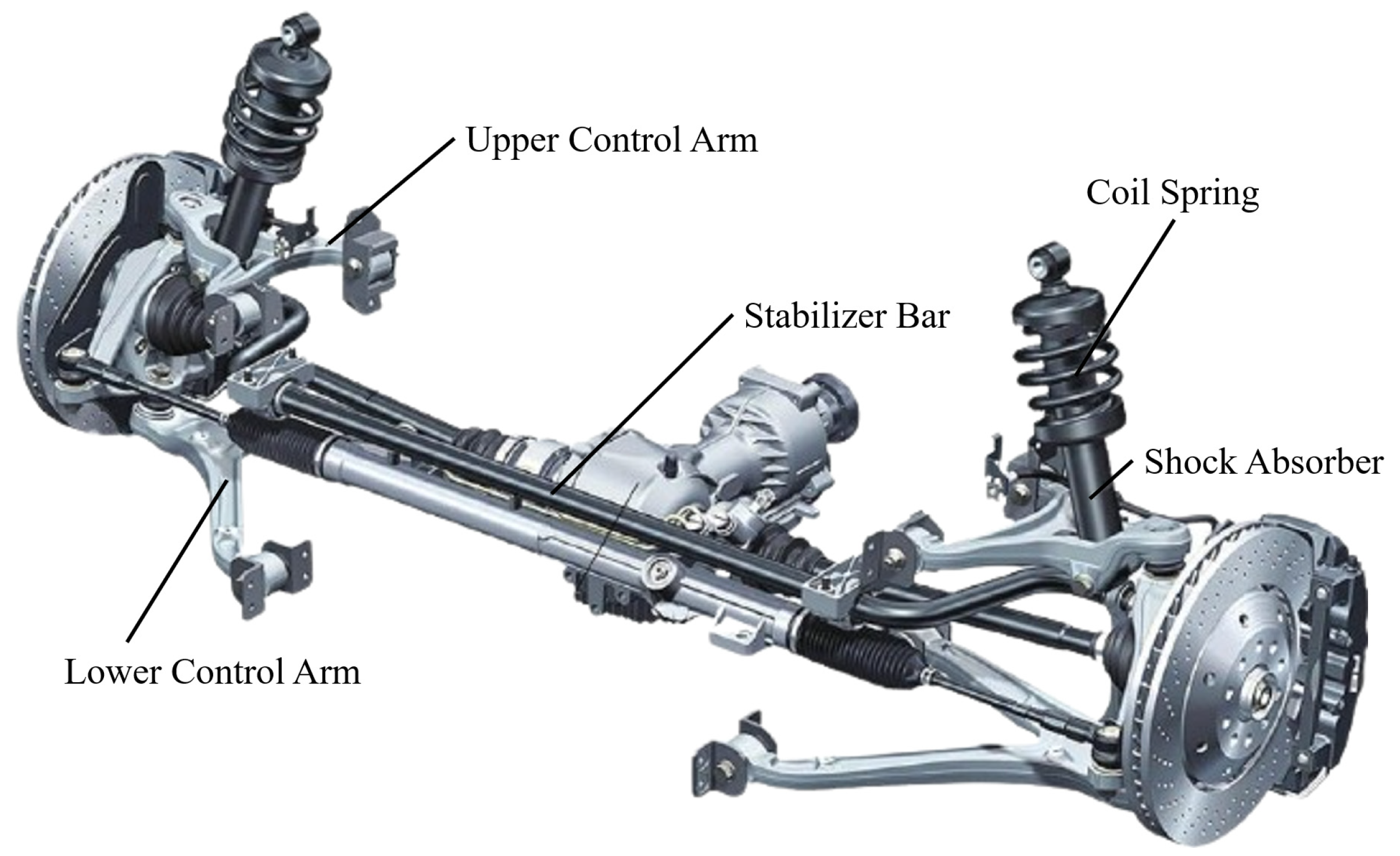
2. Suspension Systems

2.1. Functions of the Suspension Systems

Suspension is a critical component of modern automobiles. It typically comprises elastic elements, guiding mechanisms, dampers, buffer blocks, and lateral stabilizers, which elastically connect the body to the axle, as shown in Figure 1. The elastic elements bear the load, the guiding mechanisms ensure that the suspension components move along specific trajectories, and the dampers dissipate the vibrational energy transmitted by the spring mechanisms. Thus, the primary function of the suspension is to transmit all forces and moments between the wheels and the frame, mitigate the impact loads transmitted from the road to the frame, and attenuate the vibrations induced in the load-bearing system. Furthermore, it ensures that the vehicle maintains ideal dynamic characteristics when driving on uneven surfaces and under varying load conditions, ensuring handling stability and enabling high-speed driving capability. As consumer demands for enhanced vehicle performance continue to escalate, the importance of ride comfort and safety has become more pronounced; both factors are closely related to the suspension system. Consequently, suspension plays an increasingly important role in automotive design.
The body acceleration, suspension dynamic deflection, and tire dynamic load are important metrics for evaluating the ride comfort and handling stability of automobiles. The suspension is tasked with mitigating and absorbing vibrations from the wheels, while also transmitting driving and braking forces between the wheels and the road surface during vehicle operation. During vehicle maneuvers, the suspension must withstand lateral forces from the body and effectively suppress pitching vibrations during acceleration and braking. These functions significantly enhance the vehicle’s stability and safety.

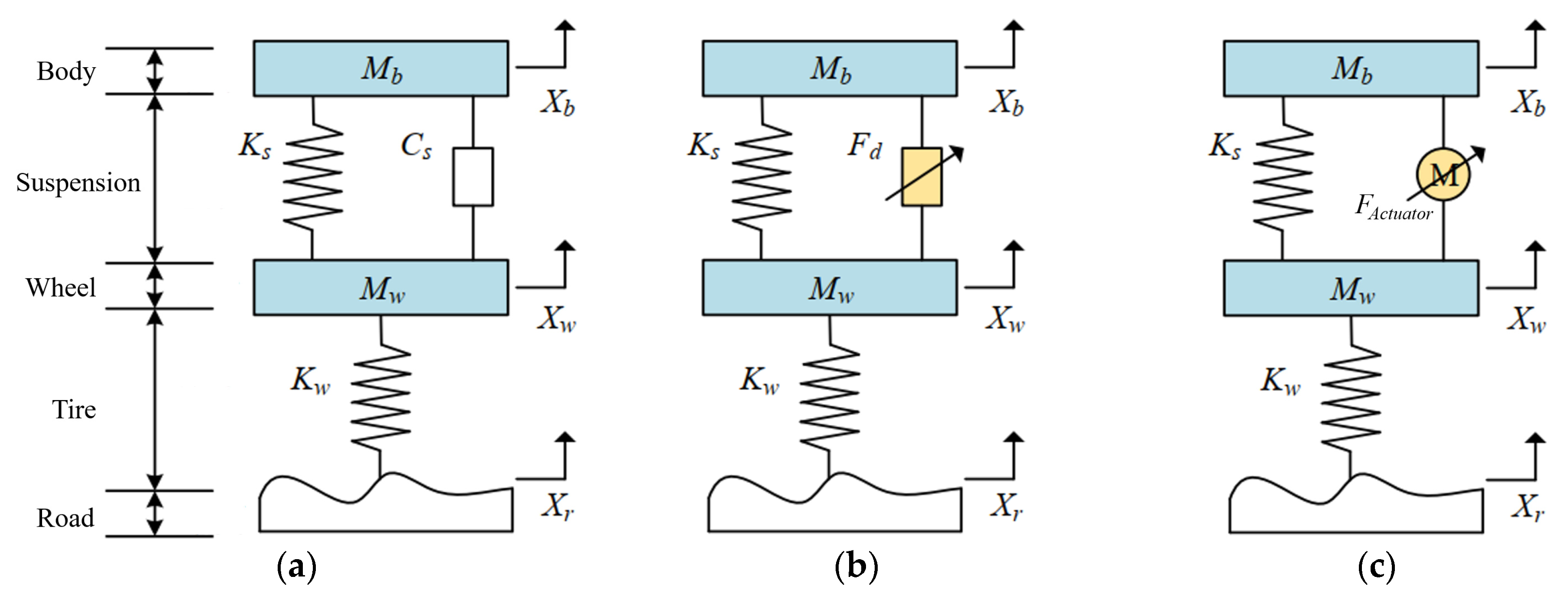
2.2. Types of the Suspension Systems

Currently, the development of suspensions has advanced to effectively adapt to various road conditions. Based on existing research and the usage of vehicles in the market, suspensions are primarily categorized into three types: passive suspension, semi-active suspension, and active suspension, depending on whether the dampers can adjust their damping autonomously and whether external energy is required during operation, as shown in Figure 2. Additionally, suspensions can be classified into traditional passive suspensions and intelligent control suspensions based on the presence of a control unit. Obviously, active and semi-active suspensions belong to the category of intelligent control suspensions.
As a conventional mechanical suspension system, passive suspension is characterized by its simple structure, reliable performance, and low cost. Undoubtedly, it is currently the most mature technology and the most widely used suspension system in the market, with the longest development history. It operates without requiring external energy input, but its stiffness and damping coefficients remain fixed and cannot adjust according to road conditions, thereby limiting its effectiveness in vibration reduction. Due to its inability to adapt to varying road conditions, vehicles equipped with passive suspension systems struggle to simultaneously optimize handling stability and ride comfort, thus failing to achieve optimal performance [21,22]. Throughout vehicle operations, it primarily serves the fundamental role of providing basic damping to facilitate smooth vehicle travel.
Regarding the shortcomings of passive suspension’s fixed damping forces, the concept of “active suspension systems” was first proposed by Labrosse in 1955 [23] and initially piloted on Citroën cars [24]. Active suspension systems replace the springs and damping elements of passive suspensions with actuators capable of adjusting output forces in real time based on vehicle and road conditions, thereby optimizing vehicle performances across all road surfaces [1,2]. This advancement significantly enhances both vehicle comfort and safety, representing the pinnacle of suspension development and offering superior ride quality among the suspension types currently available. As scholars delved deeper into research, various types of active suspensions emerged. However, they are characterized by intricate structures, high energy consumption, elevated costs, and reduced reliability. In cases where control system signals are lost or actuator failures occur, the suspension may completely lose its damping function and even potentially exacerbate vehicle vibrations. Currently, active suspension systems are predominantly installed in a limited number of high-end vehicle models, posing challenges for widespread application.
The semi-active suspension system bridges the gap between passive and active suspensions, offering enhanced damping performance compared to passive suspensions while consuming less energy than active counterparts. During vehicle operation, the controller of a semi-active suspension adjusts the stiffness of elastic components or the damping coefficient of dampers in response to variations in road conditions [3,4], thereby suppressing vibrations in the suspension system. In the event of control algorithm failure, it can function as a passive suspension. Depending on the adjusted mechanism, semi-active suspensions can be categorized as stiffness-adjustable or damping-adjustable suspensions. Semi-active suspensions retain the inherent characteristics of passive suspensions without the addition of external actuators, often replacing traditional passive dampers with units that feature adjustable damping coefficients. This design addresses the structural complexities, energy consumption, costs, and reliability issues associated with active suspensions, while achieving damping effects comparable to active suspensions. Consequently, it facilitates the expansion of controllable suspension systems from exclusive use in high-end vehicle models to broader applications across a wider range of vehicles. Common types of semi-active suspensions currently include magnetorheological (MR) suspensions, electromagnetic valve suspensions, and air suspensions.
In summary, semi-active suspension systems exhibit superior damping effectiveness compared to passive suspensions, featuring faster response speed and enhanced adaptability to varying road conditions. When appropriate control strategies are implemented, semi-active suspensions achieve damping performance comparable to active suspensions, alongside benefits such as simpler structure and reduced energy consumption. Considering cost constraints and development expenses, semi-active suspensions combine the reliability of passive suspensions with well-balanced handling stability and ride comfort, thus presenting promising prospects. Researchers have extensively researched semi-active suspensions, thus establishing them as the most widely deployed controllable suspension system in today’s market.
As shown in Table 1, the performance advantages, disadvantages, and application ranges of the three types of suspensions mentioned above are listed. The table provides a clear illustration of the distinct strengths and weaknesses of passive and active suspensions. In contrast, semi-active suspensions integrate the structural simplicity of passive suspensions with the variable damping capability of active suspensions.

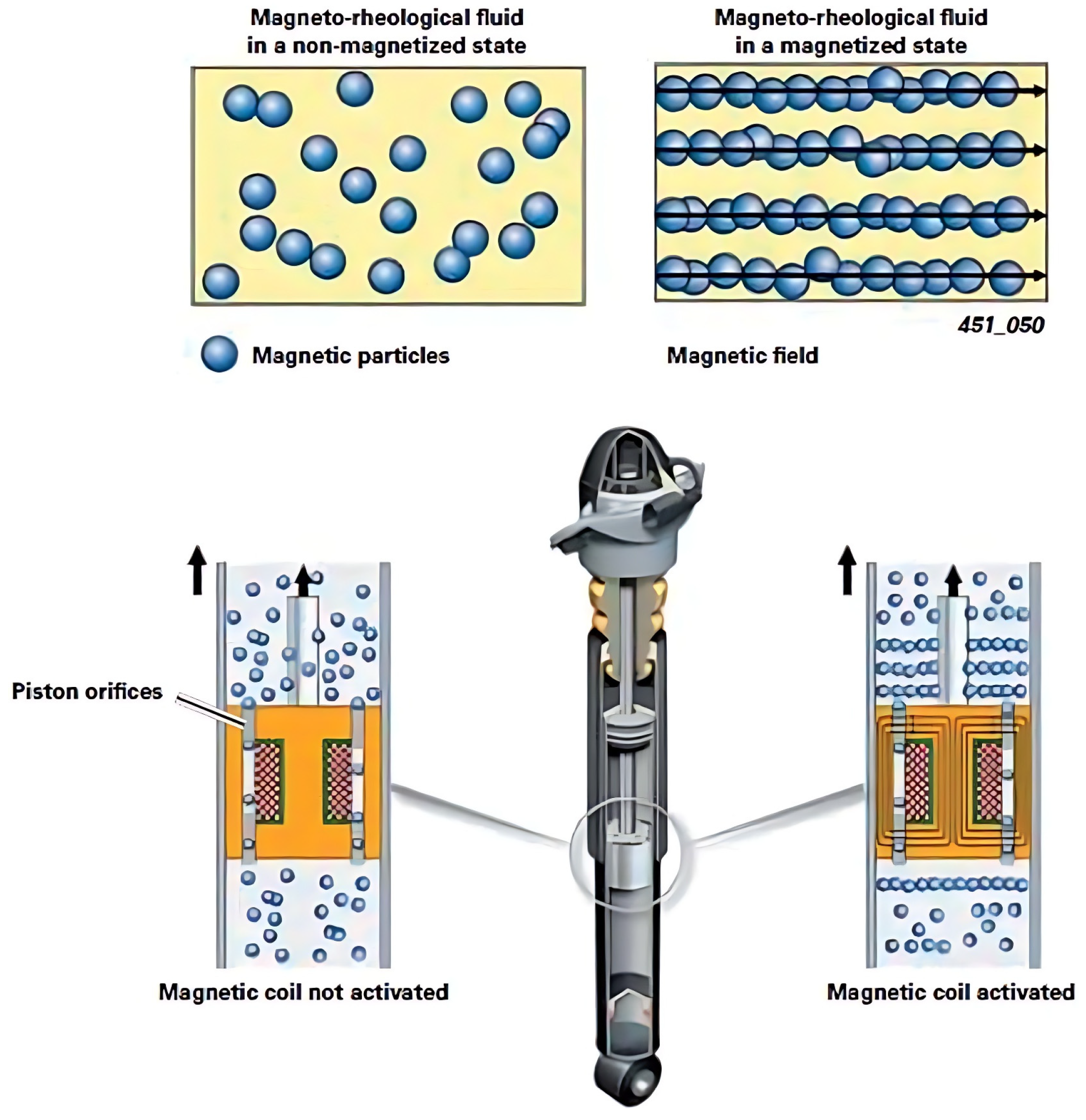
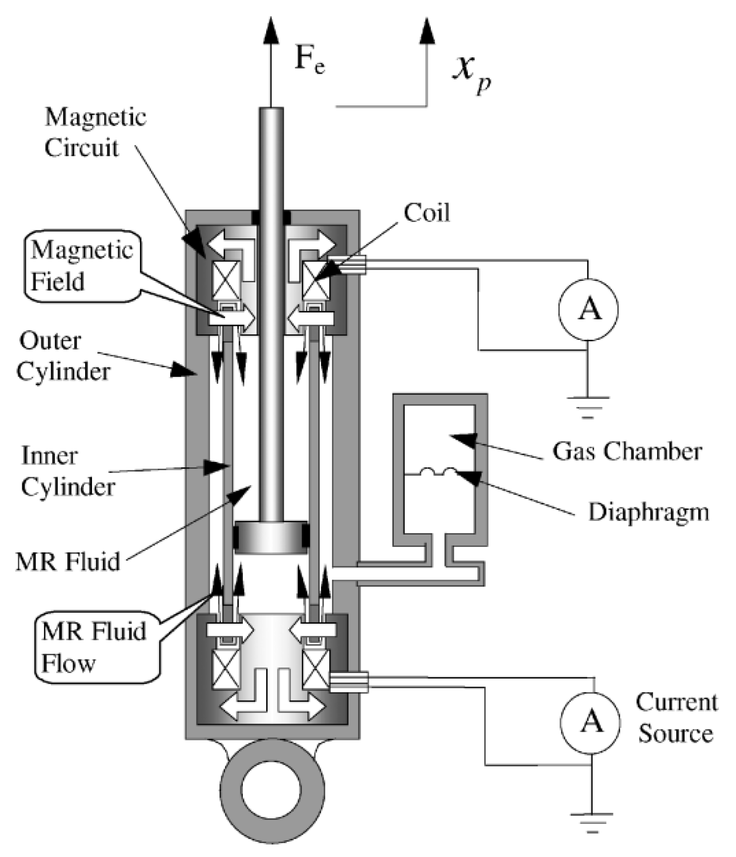
3. Magnetorheological Dampers (MRDs)

MRDs represent a novel class of intelligent damping devices utilizing MRF as their filling material, widely employed in semi-active suspension systems. Their operational principle involves altering the viscosity of the MRF by manipulating magnetic fields that orderly align magnetic particles within the fluid under magnetic influence, thereby increasing its viscosity [5,25], as illustrated in Figure 3 [25]. They are distinguished by rapid response speed, excellent reversibility, compact size, low energy consumption, the ability to adjust damping force continuously across a wide range, and high reliability. Currently, they have found extensive applications in the aerospace, construction, and automotive industries. In recent years, there has been a notable upsurge in research efforts focused on MRDs at prominent universities and research institutions [26].
The design of MRDs is intricate, involving multiple physical factors such as fluid dynamics, circuits, magnetic fields, and dynamics. Their dynamic characteristics depend on factors such as magnetic field distribution, current intensity, fluid properties, and damper structure, posing significant challenges in research. The technology of MRF was initially discovered and successfully developed by American scholar Rabinow in 1948 [27]. In 1953, Winslow proposed the application of controllable fluids in dampers and designed a controllable damper capable of smoothly adjusting damping force over a wide range [28]. However, over subsequent decades, this technology did not attract widespread attention from industry and research institutions. In recent years, MRF has garnered attention compared to electrorheological fluid (ERF) due to its exceptional material properties and performance advantages, leading to the introduction of various new MRF products.
The American company Lord Corporation is a pioneer in applying MRF technology to the commercial sector. In 1994, Carlson and Chrzan proposed the use of MRF in controllable dampers, addressing issues associated with ERF, such as low yield strength, high input requirements, and vulnerability to environmental contamination [29]. Following this, numerous researchers began applying MRF in dampers and conducted extensive experimental studies. By adjusting the intensity and direction of the magnetic field, they controlled the rheological properties of MRF to achieve regulation and control of the dampers. Studies have demonstrated that MRF exhibits excellent characteristics such as reversibility and fast response speed. With continuous development and improvement of MRF technology, the performance and control precision of MRDs have been further enhanced, laying a solid foundation for their widespread application in automotive, aerospace, and architectural fields [5]. Between 1990 and 1995, Lord Corporation filed numerous patents related to MR technology, with a primary focus on research into MRF formulations and damper designs [29,30].
The University of Maryland was among the pioneering academic institutions to initiate theoretical research on MRDs, earning multiple accolades in the field of intelligent materials and structural design for dampers [31,32]. Their research achievements have been widely applied in the aerospace, automotive, and healthcare sectors. At the University of Nevada, Pare designed an MRD capable of bearing dynamic suspension loads for specialized vehicles, providing a broader range of adjustable damping force [33]. In 2000, Choi et al. developed an innovative twin-tube MRD and integrated it into the semi-active suspension system of a bus, as shown in Figure 4. To control this semi-active suspension system, a skyhook PID controller was also designed [7]. Lindler et al. optimized the structure of MRDs and proposed a compensatory MRD (shown in Figure 5), effectively addressing the issue of sedimentation of MRF during operation [34]. Hitchock et al. from the University of Nevada designed and manufactured an MRD capable of handling electrical controller failures. Experimental results demonstrated that this MRD could continue to operate even when the input current was not properly introduced [35]. Chen and Liao proposed self-inductive and self-powered damper technology by measuring the dynamic response of MRDs. This technology is environmentally friendly, reduces the weight and size of the damper, lowers maintenance costs, and offers enhanced controllability [8]. Yazid et al. developed a three-coil shear valve type MRD, as shown in Figure 6. Experimental results indicated that increasing the number of coils significantly improved the damping force of the MRD [6]. Sohn et al. designed an MRD with a piston head featuring bypass holes, expanding the adjustable range of the damping force by reducing the damping force in the low-speed region, as shown in Figure 7 [36]. To enhance the response speed of MRDs, Strecker et al. designed a special current controller for the excitation coil, reducing the response time to 0.5 ms [9].

4. Semi-Active Control of Suspension Systems

MR semi-active suspension systems are complex nonlinear systems influenced by multiple factors. Enhancing vehicle ride comfort hinges on optimizing suspension control strategies rooted in enhanced vehicle structures, thereby crucially enhancing overall vehicle performance. This stands as a focal point in extensive research. Presently, scholars have delineated various strategies in this field, which can be broadly classified into three categories: classical control strategies, modern control strategies, and intelligent control strategies.

4.1. Classical Control Strategies

The classical control strategies of semi-active suspensions primarily comprise skyhook control, groundhook control, and hybrid control strategies.

4.1.1. Skyhook Control

Skyhook damping control, proposed by Karnopp et al. in 1974, is a classic suspension control strategy [37]. Its core principle posits an ideal skyhook damper, affixed at one end to the vehicle body and at the other end to the “absolutely stationary” sky, thereby transmitting damping force exclusively to the vehicle body without affecting the unsprung mass, thus achieving vibration reduction. However, practical vehicle suspension systems inherently retain coupling between the vehicle body and unsprung mass, precluding the isolation of damping forces solely to the vehicle body. Nonetheless, skyhook control has demonstrated significant enhancements in vehicle ride quality.
Margolis et al. proposed integrating switch control into skyhook damping, where the damper’s switching state is determined by the velocities of the unsprung and sprung masses [38]. The damper switches to the “off” state when the velocity of the unsprung mass exceeds that of the sprung mass and their directions align; otherwise, it remains “on”. This constitutes a switching control strategy to adjust damping levels according to control demands, thereby accommodating vehicle body vibrations under different conditions. However, due to its toggling nature, this control approach may induce jitter in the suspension system.
To eliminate jitter phenomena, Ahmadian and Vahdati conducted in-depth research on switch-type skyhook control and proposed a jitter-free skyhook control method [10]. Sammier et al. devised a continuous linear skyhook control strategy to counteract the jitter induced by switch-type skyhook control [39]. Shimoya and Katsuyama introduced an enhanced energy-efficient skyhook control that integrated active control and energy recovery technologies, effectively managing the system’s dynamic performance and energy consumption issues through efficient switching conditions [40], as illustrated in Figure 8. Du et al. proposed an adaptive skyhook damping control algorithm and employed genetic algorithms to optimize the optimal control gain coefficients for skyhook damping control across varying vehicle speeds [41], as shown in Figure 9. Liu et al. presented an advanced skyhook damping control method based on real-time estimation of road surface conditions, enabling optimal control parameters according to different vehicle speeds and road surfaces [42]. Ma et al. developed a skyhook damping controller based on an inverse model of the MRD and refined it using the grey wolf optimization algorithm, thereby reducing vehicle acceleration, suspension travel, and tire dynamic loads [43].
For the convenience of signal acquisition, Savaresi et al. proposed an Acceleration-Driven Damping (ADD) control strategy [44,45]. This strategy’s control logic parallels that of skyhook control, but instead of relying on the velocity of the sprung mass, it evaluates the relationship between the acceleration of the sprung mass and the relative velocity of the suspension. ADD control effectively attenuates high-frequency vibrations, while skyhook control excels in mitigating low-frequency vibrations. Consequently, Savaresi and Spelta integrated these two control algorithms to propose a Hybrid Skyhook-ADD (SH-ADD) damping control strategy [46]. This approach employs a switching control methodology, adapting the control strategy according to the frequency of the current road excitation, thereby achieving superior ride comfort across the entire frequency spectrum.

4.1.2. Groundhook Control

Based on the principle of damping control analogous to skyhook damping, Valasek et al. [11] and Pare [33,47] successively proposed groundhook damping control algorithms. Unlike skyhook damping, which prioritizes vehicle ride comfort, groundhook damping control aims to improve road adherence and vehicle stability. Its fundamental principle resembles skyhook, involving the addition of a groundhook damper connecting the unsprung mass to the ground coordinate system, providing damping force proportional to the velocity of the unsprung mass [48]. In 2003, Koo et al. introduced a switch-type groundhook damping control, applying a similar algorithm to practical vehicles and achieving favorable control outcomes [49]. Groundhook damping control has found extensive application in commercial vehicle suspension systems, effectively reducing tire dynamic loads and minimizing the damage caused by commercial vehicle wheel loads on road surfaces.

4.1.3. Hybrid Control

Ahmadian proposed a hybrid control method that integrates the advantages of skyhook and groundhook strategies using weighting coefficients to optimize their benefits and mitigate their drawbacks [12]. Goncalves and Ahmadian further refined this approach by synergizing the strengths of skyhook and groundhook controls, emphasizing the critical role of weighting coefficients in determining control efficacy [50]. Mulla et al. examined the effects of skyhook, groundhook, and hybrid control strategies on semi-active suspension systems, evaluating suspension performance metrics under step input conditions [51]. The findings suggested that skyhook dampers outperformed other controllers in terms of ride comfort and handling.

4.2. Modern Control Strategies

The modern control strategies of semi-active suspension primarily comprise optimal control, model predictive control, robust control, and adaptive control strategies.

4.2.1. Optimal Control

Optimal control is a widely applied algorithm for determining parameters in linear controlled systems. Prominent optimal control algorithms include Linear Quadratic Regulator (LQR) and Linear Quadratic Gaussian (LQG) control [13,14]. The core concept of optimal control involves formulating the system’s state equations and defining an optimization function for control objectives (typically focusing on ride comfort and stability in suspension systems). Riccati’s formula is employed to calculate the feedback gain matrix at the extremal state, which then serves as the controller output to achieve the system’s optimal controlled state. This method was initially applied to active suspensions by Thompson [52].
For nonlinear systems, Tseng and Hedrick proposed the fastest gradient control method by transforming the nonlinear suspension system into a time-varying problem of a linear system, based on the improved optimal control theory [53]. Karkoub and Zribi developed a half-vehicle MR semi-active bus suspension model with six degrees of freedom and designed an optimal control strategy utilizing acceleration feedback [54]. Chen et al. demonstrated that when the baseline damping of the semi-active suspension was low, the vibration reduction performance of the LQG-based semi-active suspension could rival that of an active suspension, underscoring the high compatibility of the LQG control strategy with semi-active suspensions [55]. Unger et al. designed an LQR full-vehicle semi-active suspension controller based on a full-vehicle suspension model. Simulation and experimental data showed that the LQR-controlled semi-active suspension significantly enhanced ride comfort [56]. Hirao et al. established a half-vehicle suspension model and designed LQR (shown in Figure 10) and PID controllers, finding that the LQR controller outperformed the PID controller in handling transient response and overshoot [57]. Prassad and Mohan developed an LQR-based adaptive air suspension system and conducted simulation comparisons with the widely used PID controller [58]. The results indicated that the LQR control strategy significantly enhanced ride comfort and reduced the settling time by 85%. In addressing parameter uncertainty in skyhook damper suspension systems, Rao and Narayanan proposed a skyhook damper based on the LQR algorithm [59]. The principle involves utilizing the LQR control algorithm to calculate the active suspension control force, thereby determining the unknown parameters in the skyhook damper. The results demonstrated superior control performance under random road excitations.

4.2.2. Model Predictive Control (MPC)

Although linear quadratic optimal control can directly obtain the optimal feedback matrix, it fails to account for system constraints, thereby limiting its practical application. In contrast, MPC considers system dynamics constraints when solving the optimization problem within a finite time horizon, making the control more practical for real-world use. MPC gained widespread application in the control field during the 1980s [60]. The fundamental steps of MPC include predicting future system states, optimizing the open-loop system, and applying the optimization results to the system. With the rapid advancement of science and technology, the online solving capability of controllers has significantly improved. This progress has catalyzed extensive research and rapid development of MPC by scholars.
Gordon and Sharp were among the pioneers in applying the concept of MPC to analyze the impact of different prediction horizons on the control performance of semi-active suspension systems in the frequency domain [15]. Giorgetti et al. conducted comparative studies on the effects of constrained optimal control, unconstrained optimal control, and MPC [61]. They found that when the control time horizons were set to 1, MPC achieved the same performance as constrained optimal control. Furthermore, MPC’s performance progressively improves as the control time horizons increase. Canale et al. enhanced MPC by utilizing system affine theory, thereby reducing the online solution time of the MPC algorithm [62]. Ahmed and Svaricek validated the control efficacy of MPC (shown in Figure 11b) using a half-vehicle suspension model (shown in Figure 11a) across various frequency bands [63,64]. Nguyen et al. applied MPC to the semi-active suspension control of passenger vehicles, demonstrating favorable ride comfort results through simulation analysis [65].

4.2.3. Robust Control

During vehicle operation, the suspension system encounters not only complex and diverse operational conditions but also exhibits several inherent nonlinear characteristics. These include the nonlinearity of suspension spring stiffness, the hysteresis characteristics of MRDs, and the vibration coupling between sprung and unsprung masses. Consequently, a discernible accuracy gap exists between practical suspension systems and theoretical models in control systems. Robustness in control denotes the ability to maintain predetermined performance despite parameter perturbations in the control system. Robust control is denoted for its robust disturbance rejection capabilities, cost-effectiveness, and avoidance of online adjustments to controller parameters, thus establishing widespread application in practical control systems.
The robustness of control strategies has long been a focus in academic research, with H control emerging as the pioneering theory for addressing robustness in control systems. H control is a robust control method that aims to minimize the worst-case gain from disturbance to output, ensuring system stability and performance under model uncertainties and external disturbances. Semi-active suspensions introduce specific dynamic constraints due to their damping characteristics, prompting H control to aim for minimal control force error application towards ideal levels, thereby fulfilling precise control specifications. Choi et al. treated the sprung mass of semi-active suspensions as an uncertain factor, proposing a robust H control method (illustrated in Figure 12) and evaluating the damping characteristics of such suspensions under diverse road conditions [16]. Shimoya and Katsuyama designed an H control method based on a single-wheel suspension model, demonstrating the enhanced comfort and superior road handling performance of controlled semi-active suspensions compared to passive counterparts [40]. In 2005, Du et al. developed a static output feedback H anti-windup controller for MRDs in semi-active suspensions, significantly enhancing both ride comfort and road grip [66]. Chen et al. reformulated the control problem as a constrained vibration attenuation problem and designed a constrained H controller based on linear matrix inequalities [67]. Félix-Herrán et al. addressed uncertainties in the sprung mass of MRD suspensions by optimized H controllers [68]. Choi et al. introduced a multi-objective synthesis approach, leveraging integral inequality methods and linear matrix inequalities to design a novel dynamic output feedback H controller [69]. Shao et al. developed a robust H output feedback controller to handle active suspension control issues involving unmeasurable parameters such as dynamic damper velocities and sprung mass velocities, addressing actuator failures and time delays [70]. This controller ensures system asymptotic stability while meeting requirements for traction and ride comfort.
Sliding mode control stands as a widely adopted robust control method in vehicle semi-active suspension systems. This approach achieves effective regulation by meticulously designing switching functions and sliding mode convergence rates, ensuring the controlled system operates precisely on the sliding surface, thereby closely approximating the behavior of an ideal model. Choi et al. designed a sliding mode controller specifically for semi-active suspensions, demonstrating the insensitivity of the sliding mode control algorithm to suspension parameter variations and highlighting its advantages in semi-active suspension control [71]. Yohayama et al. addressed the nonlinear characteristics of MRDs by designing a sliding mode variable structure controller based on an ideal skyhook control model [72]. Chen adopted the ideal skyhook control as a benchmark for sliding mode control, with a focus on comfort-oriented control strategies [73]. In 2019, Rui proposed a novel nonlinear adaptive sliding mode control strategy suitable for Electronic Controlled Air Suspension (ECAS) [74]. Yang et al. investigated an improved adaptive sliding mode fault-tolerant control strategy applied to semi-active MR suspension systems, as illustrated in Figure 13 [75]. The effectiveness of the proposed control schemes was validated by numerical simulations based on experimental data from a quarter-vehicle test rig.

4.2.4. Adaptive Control

The vehicle suspension system, characterized as a nonlinear system, is subject to various disturbances during operation. Adaptive control offers a solution by automatically optimizing controller parameters based on the vehicle’s current driving state. Extensive research has been conducted on the application of adaptive control in suspension systems. Huang et al. proposed a road-condition adaptive nonlinear control method, which can adjust the shape of the filter in real time according to the collected variations in the dynamic travel of the suspension [17]. Li et al. developed an adaptive sliding mode controller integrated with fuzzy control to address the nonlinearity of suspension systems [76]. The variations in sprung mass and unsprung mass were considered and the corresponding mathematical model was established. Koch and Kloiber proposed an adaptive vehicle suspension control method, where the controller adjusted parameters based on the current driving conditions [77]. Simulation and experimental validation indicated that suspension systems employing this control method significantly enhanced ride comfort while maintaining safe ranges for wheel load and suspension stroke. Yildiz et al. proposed a nonlinear adaptive controller for a quarter-vehicle semi-active suspension system equipped with MRDs [78]. The controller addressed uncertainties associated with the vehicle suspension model and MRDs, incorporating a nonlinear observer to estimate the internal state variables of the MRDs. Nichielea and Unguritu introduced an adaptive harmonic control method that utilized vertical body acceleration feedback to generate harmonic control signals with variable amplitude and frequency [79]. Simulation studies revealed that this control method outperformed alternative algorithms in certain scenarios.

4.3. Intelligent Control Strategies

Due to the uncertainty inherent in control systems and the complexity of vehicle operating environments, both classical and modern control strategies exhibit limitations. In response to this challenge, researchers have increasingly turned to artificial intelligence techniques. Intelligent control strategies have arisen alongside the rapid progress in computer technology and artificial intelligence. Analogous to machine learning, intelligent control evaluates vehicle operating conditions based on existing data or rules formulated by experts and, subsequently, implements appropriate control adjustments. Prominent intelligent control algorithms include fuzzy control, neural network control, and bio-inspired optimization algorithms [80].

4.3.1. Fuzzy Control

In the field of intelligent control, fuzzy control stands out for its strong capability in managing nonlinear systems. For systems characterized by strong nonlinearity and uncertainty, such as vehicle semi-active suspension systems employing MRDs as actuators, fuzzy control emerges as an exceptionally suitable control algorithm. As early as 1965, the American scholar Zadeh pioneered fuzzy set theory [81]. Grounded in this theoretical framework, fuzzy control theory articulates control and state variables in fuzzy language. By translating engineering expertise and expert knowledge into fuzzy rules, it establishes mappings between control variables and state variables, thus effectively controlling the system [82,83]. Fuzzy controllers do not necessitate exhaustive knowledge of all state variables; instead, they adeptly regulate highly nonlinear systems with minimal sensors based on control logic.
Al-Holou et al. employed fuzzy logic in the control of semi-active suspension, with vehicle body velocity and suspension velocity as inputs, and damping force as the output [18]. The study indicated that semi-active suspension systems based on fuzzy control exhibited markedly superior comfort performance compared to passive suspensions. Rao and Prahlad developed a self-tuning fuzzy controller for active suspension systems [84]. Caponetto et al. proposed a fuzzy skyhook damping controller based on the quarter-vehicle model [85]. This controller optimally adjusted the characteristics of the skyhook damping suspension in response to changing road conditions. Guclu utilized a fuzzy controller for systematic vibration control in an eight-degrees-of-freedom nonlinear vehicle model [86]. Demir et al. utilized fuzzy control to optimize the hyperparameters of the PID controller [87]. This approach effectively mitigated the challenge of real-time PID parameter adjustment. Kasemi et al. conducted comparative studies on passive suspension, PID-controlled semi-active suspension, and fuzzy PID-controlled semi-active suspension [88]. The research findings indicated that the control effectiveness of fuzzy PID was significantly superior to the former two methods. Kurczyk and Pawelczyk developed a fuzzy controller for a vehicle suspension system, focusing on damping force as the controlled variable [89]. Notably, this controller operated effectively without the need for an inverse model of the MRD. Tang et al. introduced a Takagi–Sugeno fuzzy controller based on a state observer. Simulation studies demonstrated the controller’s proficient management of suspension performance [90]. Peng et al. designed an adaptive fuzzy inference system based on an MR semi-active suspension model to formulate a non-parametric damper model [91]. Additionally, they developed a Takagi–Sugeno fuzzy controller. Nguyen et al. proposed an optimal fuzzy control approach that optimized the control law using genetic algorithms [92]. They validated the control algorithm through simulation based on a three-dimensional nonlinear dynamics model. Li et al. proposed a fuzzy sliding mode control (FSMC) strategy for a semi-active air suspension system based on MRDs (shown in Figure 14), investigating the application of fuzzy control to adjust the sliding mode control boundary layer [93]. Experimental results indicated that the semi-active air suspension with FSMC exhibited improved damping performance and ride comfort.

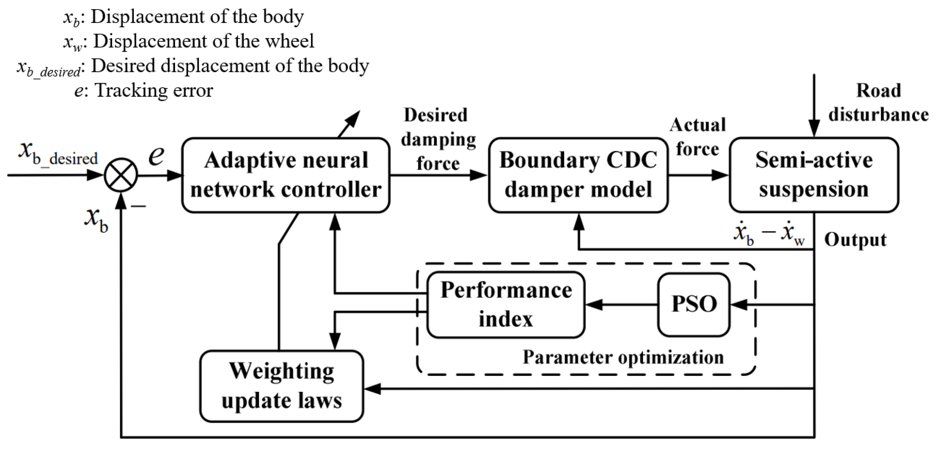
4.3.2. Neural Network Control

The neural network control continuously learns information from the controlled system through mechanisms such as neuron self-learning and self-memory. Its advantages lie in its strong adaptability and robustness, making it well-suited for addressing control challenges posed by system nonlinearity, uncertain parameters, or response delays [94]. Jin and Yu developed an error-integrated neural network control and implemented it in an active suspension system, demonstrating its robustness in system control [95]. Liu et al. proposed a method employing adaptive neural network control to estimate the unknown mass of the vehicle [19]. They validated the feasibility and rationality of the proposed method through simulation.
Liu et al. proposed a method utilizing feedforward deep neural networks and an automatic search technique to optimize the network structure for active suspension system control [19]. Ding et al. integrated continuous damping control with adaptive neural network control for vehicle suspension systems [20], as demonstrated in Figure 15. Al Aela et al. tackled the dynamic nonlinearity of quarter-car active suspension systems by proposing an Adaptive Neural Network Control (ANNC) strategy [96]. They combined Radial Basis Function Neural Networks (RBFNN) with a backstepping controller to enhance suspension performance and effectively handle uncertainties in the system model. Lin et al. proposed a control strategy based on reinforcement learning inverse control for active suspension system design [97]. In pursuit of the optimal virtual control force, they formulated a Deep Deterministic Policy Gradient (DDPG) control framework.

4.3.3. Bio-Inspired Optimization Algorithms

In recent years, bio-inspired optimization algorithms rooted in simulated biological systems, such as Particle Swarm Optimization (PSO), Genetic Algorithms (GA), Non-dominated Sorting Genetic Algorithm II (NSGA-II), and Ant Colony Optimization (ACO), have undergone significant advancements and found successful applications across various domains of control.
In 2017, Ding Z et al. implemented an Adaptive Neural Network (ANN) control strategy in a Continuous Damping Control (CDC) suspension system and utilized experimental data from CDC dampers to establish a boundary model for analyzing its dynamic characteristics [20]. Addressing uncertainties and nonlinearities in suspension system parameters, with the optimization objective focused on spring displacement, they employed Particle Swarm Optimization (PSO) to tune and optimize controller parameters. In 2017, Ab Talib and Darus proposed an Intelligent Fuzzy Logic (IFL) control strategy utilizing a quarter-vehicle model [98]. They aimed to minimize the Mean Square Error (MSE) of body displacement, acceleration, and suspension deflection angle. They utilized the Firefly Algorithm (FA) and Particle Swarm Optimization (PSO) to optimize the weighting factors of the Intelligent Fuzzy Logic (IFL). In 2019, Samsuria et al. employed the Particle Swarm Optimization (PSO) algorithm to optimize the Linear Quadratic Regulator (LQR) and Sliding Mode Control (SMC) strategies [99]. They employed weighted parameters and integral absolute error as the respective objective functions. In 2020, Dahunsi et al. employed various global optimization algorithms, including Differential Evolution (DE), Controlled Random Search (CRS), Modified Controlled Random Search (MCRS), Particle Swarm Optimization (PSO), and Modified Particle Swarm Optimization (MPSO), to achieve optimal trade-offs between indicators such as sprung mass displacement and tire grip performance in a nonlinear electro-hydraulic active suspension system [100]. In 2021, Cao et al. tackled the limitations of traditional PID control strategies for air suspension, such as extended tuning durations and fixed control parameters [101]. They introduced a lateral interconnected electronic control strategy for air suspension, leveraging the Seeker Optimization Algorithm (SOA). In 2022, Manna et al. proposed a Linear Quadratic Regulator (LQR) strategy to enhance the real-time adjustment control performance of Active Suspension Systems [2]. Additionally, they employed a novel Ant Colony Optimization (ACO) algorithm to conduct multi-objective optimization of the weights in LQR.
Despite the achievements of intelligent control strategies, several issues persist. For instance, fuzzy rules exhibit considerable variability among individuals, posing challenges in their generalization and evaluation. The foundational principles of neural network control lack clarity and struggle to achieve effective control in data-scarce scenarios. Additionally, genetic algorithms are prone to getting trapped in local minima. As a result, the research focus on intelligent control is progressively pivoting towards composite control, which integrates modern control with intelligent control.

5. The Practical Applications of the MR Semi-Active Suspensions

In 1999, the Lord Corporation and Delphi Corporation collaborated to pioneer the MagneRide system, a semi-active suspension technology utilizing MRD. This groundbreaking initiative marked MRD’s inaugural application in semi-active suspensions. In 2002, the MagneRide suspension system was first implemented in the Cadillac Seville STS model. Following its outstanding performance in this vehicle, it immediately captured the interest of leading performance car manufacturers. As technology evolved, the MagneRide system became widely integrated into numerous high-end vehicle models, catalyzing significant advancements in automotive suspension systems. Empirical findings underscored that vehicles equipped with the MagneRide system not only enhanced driving stability but also elevated ride comfort while substantially diminishing vehicle vibrations, thereby solidifying the reliability of MRD.
The successful trials of MRD in semi-active vehicle suspensions have ushered in a new era for semi-active suspension systems. Furthermore, these trials have spurred ongoing improvements in MRD for vehicle damping, hastening advancements in the contemporary high-end automotive industry. Figure 16 illustrates the implementation of MRD in prominent high-end vehicles in an annalistic style as of 2024.
From Figure 16, several important milestones (highlighted in red) can be discerned: in 2002, MagneRide made its first integration into a production vehicle; in 2006, it was adopted by the first non-General Motors vehicle; 2007 saw its debut in a full-size luxury SUV; in 2012, it was first employed in an off-roader; 2015 marked Ford’s initial introduction of it in the Mustang series; and in 2021, it was first implemented in an electric vehicle.
From the vehicle history depicted in Figure 16, it can be inferred that the application of MagneRide in automobiles exhibits the following characteristics:
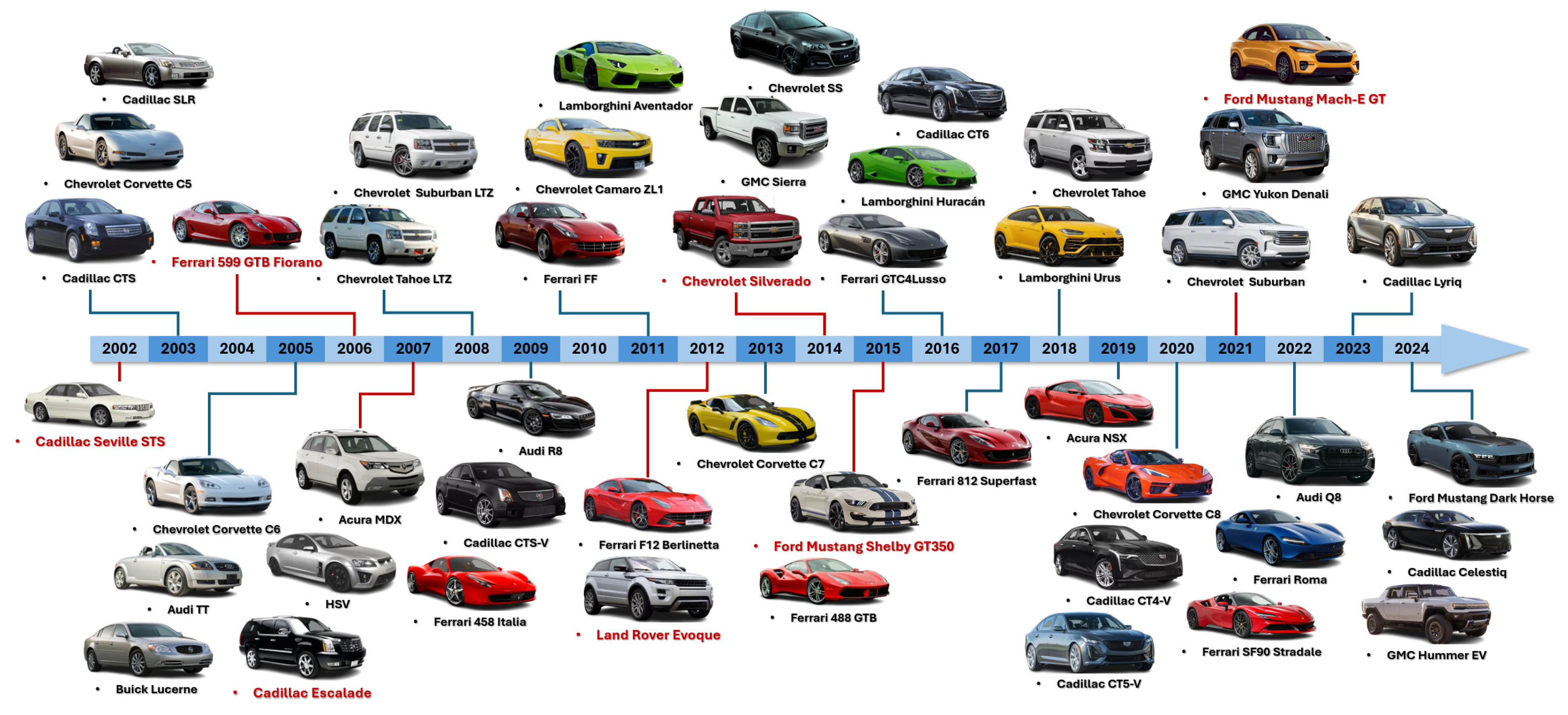
  • Inheritance: The MagneRide has been consistently applied in several vehicle models. For instance, from the Corvette C5 to C8, this technology has undergone continuous refinement aimed at improving vehicle performance and comfort. Similarly, several Ferrari models such as the 458 Italia and F12 Berlinetta also incorporate MagneRide, highlighting the ongoing evolution of this technology within high-performance sports cars. Since its initial integration, Cadillac has likewise maintained the use of this technology across various models, demonstrating its sustained application in the luxury sedan segment.
  • Versatility: Initially, MagneRide was predominantly used in sports cars and luxury sedans. Through advancements in sealing, structure, and control in its third-generation system, MagneRide has expanded its application to a wide range of vehicle types including SUVs, pickups, and off-road vehicles. Such widespread adoption ensures optimal handling and comfort whether during high-speed cruising, performance driving, or traversing challenging terrains.
  • Scalability: The application of MagneRide has progressively broadened beyond its initial high-performance vehicle models (e.g., from the 2008 Suburban LTZ and Tahoe LTZ to the 2021 Suburban and Tahoe). Originally implemented in high-performance sports cars and luxury sedans like Ferrari and Cadillac, MagneRide has in recent years found integration into mainstream vehicle models. This integration underscores a notable trend of downward compatibility and the widespread adoption of this advanced technology.
  • Electrification: MagneRide technology has adeptly responded to the evolution of automotive energy forms, shifting progressively from conventional fuel-powered vehicles to electric vehicles. The inclusion of MagneRide in models like the Ford Mustang Mach-E GT signifies a pivotal milestone in its successful integration and implementation within the electric vehicle sector. The electrification adaptability of this technology ensures that vehicles can deliver exceptional driving experiences across different energy forms.
In conclusion, the application of MRD technology in automobiles has demonstrated significant attributes in terms of inheritance, versatility, scalability, and electrification, thereby ensuring outstanding vehicle performance and user experience under diverse driving conditions. Nevertheless, due to reasons such as cost, complexity and technical difficulty, market promotion, and technological acceptance, its current predominance in high-end vehicle models underscores the considerable challenges and a prolonged journey toward widespread adoption in mainstream vehicle segments.

6. Conclusions

This paper presented a review of the advancements in semi-active suspension systems, with a particular focus on magnetorheological dampers (MRDs). The progression from traditional passive systems to active and semi-active configurations highlights the continuous pursuit of enhanced vehicle performance, comfort, and safety. Semi-active systems, especially those utilizing MRDs, offer a balanced solution that combines the simplicity of passive systems with the adaptability of active systems, without the high energy consumption typically associated with the latter. The contents of this paper can be concluded in the following aspects:
  • The paper emphasized the significant attributes of MRDs, including their rapid response, reversibility, compact size, low energy consumption, continuous damping adjustment, and high reliability. These characteristics have enabled MRDs to be widely adopted in various industries. The design and optimization of MRDs involve complex interactions among fluid dynamics, magnetic fields, and structural mechanics, with notable innovations such as twin-coil and twin-tube configurations, self-inductive and self-powered dampers, and advanced controllers enhancing their performance.
  • The various control strategies employed in semi-active suspension systems were thoroughly discussed, which can be categorized into classical, modern, and intelligent methods. These strategies play a crucial role in optimizing suspension performance and improving vehicle ride comfort and stability. The current research focus on intelligent control is progressively pivoting towards hybrid control, which integrates modern control with intelligent control, which not only enhances the adaptability and performance of semi-active suspension systems but also potentially opens new avenues for the development of autonomous vehicles.
  • The successful implementation of the MagneRide system by Lord Corporation and Delphi Corporation in 1999 marked a significant milestone in the practical application of MRDs in automotive suspension systems. The widespread adoption of MagneRide in high-end and luxury vehicles demonstrated its effectiveness in enhancing vehicle dynamics and user experience, despite challenges related to cost and technical complexity.
  • Looking ahead, enhanced integration of artificial intelligence and machine learning, the development of hybrid control strategies, advancements in sensor technology, and a commitment to energy efficiency and sustainability will drive this progress. Moreover, seamless integration with autonomous and connected vehicles, along with increased collaboration and standardization among researchers, manufacturers, and industries, will facilitate the widespread adoption and consistent performance of advanced semi-active suspension systems across more vehicle models.

Author Contributions

Conceptualization, C.L. and X.Z.; Investigation, Z.W. and L.Z.; Supervision, C.L., X.Z. and Y.Q.; Wring—Original Draft, Z.W. and L.Z.; Writing—Review and Editing, C.L., X.Z. and Y.Q. All authors have read and agreed to the published version of the manuscript.

Funding

This research received no external funding.

Conflicts of Interest

Author Liang Zhao was employed by the company Nio China Headquarters. The remaining authors declare that the research was conducted in the absence of any commercial or financial relationships that could be construed as a potential conflict of interest.

References

  1. Jia, T.H.; Pan, Y.N.; Liang, H.J.; Lam, H.K. Event-Based Adaptive Fixed-Time Fuzzy Control for Active Vehicle Suspension Systems with Time-Varying Displacement Constraint. IEEE Trans. Fuzzy Syst. 2022, 30, 2813–2821. [Google Scholar] [CrossRef]
  2. Manna, S.; Mani, G.; Ghildiyal, S.; Stonier, A.A.; Peter, G.; Ganji, V.; Murugesan, S. Ant Colony Optimization Tuned Closed-Loop Optimal Control Intended for Vehicle Active Suspension System. IEEE Access. 2022, 10, 53735–53745. [Google Scholar] [CrossRef]
  3. Mihai, I.; Andronic, F. Behavior of a Semi-Active Suspension System Versus a Passive Suspension System on an Uneven Road Surface. Mechanika 2014, 20, 64–69. [Google Scholar] [CrossRef]
  4. Yong, H.; Seo, J.; Kim, J.; Kim, M.; Choi, J. Suspension Control Strategies Using Switched Soft Actor-Critic Models or Real Roads. IEEE Trans. Ind. Electron. 2023, 70, 824–832. [Google Scholar] [CrossRef]
  5. Olabi, A.G.; Grunwald, A. Design and Application of Magneto-Rheological fluid. Mater. Des. 2007, 28, 2658–2664. [Google Scholar] [CrossRef]
  6. Yazid, I.I.M.; Mazlan, S.A.; Kikuchi, T.; Zamzuri, H.; Imaduddin, F. Design of Magnetorheological Damper with a Combination of Shear and Squeeze Modes. Mater. Des. 2014, 54, 87–95. [Google Scholar] [CrossRef]
  7. Choi, S.B.; Lee, H.S.; Hong, S.R.; Cheong, C.C. Control and Response Characteristics of a Magneto-Rheological Fluid Damper for Passenger Vehicles. In Proceedings of the Society of Photo-Optical Instrumentation Engineers, Newport Beach, CA, USA, 5–9 March 2000. [Google Scholar]
  8. Chen, C.; Liao, W.H. Feasibility Study of Self-Powered Magnetorheological Damer Systems. In Proceedings of the Active and Passive Smart Structures and Integrated Systems, San Diego, CA, USA, 12–15 March 2012. [Google Scholar]
  9. Strecker, Z.; Roupec, J.; Mazurek, I.; Klapka, M. Limiting Factors of the Response Time of the Magnetorheological Damper. Int. J. Appl. Electromagn. Mech. 2015, 17, 25–41. [Google Scholar] [CrossRef]
  10. Ahmadian, M.; Vahdati, N. Transient Dynamics of Semiactive Suspensions with Hybrid Control. J. Intell. Mater. Syst. Struct. 2006, 17, 145–153. [Google Scholar] [CrossRef]
  11. Valasek, M.; Novak, M.; Sika, Z.; Vaculin, O. Extended Ground-Hook—New Concept of Semi-Active Control of Truck’s Suspension. Veh. Syst. Dyn. 1997, 27, 289–303. [Google Scholar] [CrossRef]
  12. Ahmadian, M. A Hybrid Semiactive Control for secondary suspension applications. In Proceedings of the ASME International Mechanical Engineering Congress and Exposition, Dallas, TX, USA, 16–21 November 1997. [Google Scholar]
  13. Bubhardt, J.; Isermann, R. Realization of Adaptive Shock Absorbers by Estimating Physical Process Coefficients of a Vehicle Suspension System. In Proceedings of the American Control Conference, Chicago, IL, USA, 24–26 June 1992. [Google Scholar]
  14. Venhovens, P.J.T. The Development and Implementation of Adaptive Semiactive Suspension Control. Veh. Syst. Dyn. 1994, 23, 211–235. [Google Scholar] [CrossRef]
  15. Gordon, T.J.; Sharp, R.S. On Improving the Performance of Automotive Semi-Active Suspension Systems Through Road Preview. J. Sound Vibr. 1998, 217, 163–182. [Google Scholar] [CrossRef]
  16. Choi, S.B.; Lee, H.S.; Park, Y.P. H Control Performance of a Full-Vehicle Suspension Featuring Magnetorheological Dampers. Veh. Syst. Dyn. 2002, 38, 341–360. [Google Scholar] [CrossRef]
  17. Huang, C.J.; Lin, J.S.; Chen, C.C. Road-Adaptive Algorithm Design for Half-Car Active Suspension System. Expert Syst. Appl. 2010, 37, 4392–4402. [Google Scholar] [CrossRef]
  18. Al-Holou, N.; Joo, D.S.; Shaout, A. The Development of Fuzzy Logic Based Controller for Semi-Active Suspension System. In Proceedings of the 1994 37th Midwest Symposium on Circuits and Systems, Lafayette, LA, USA, 3–5 August 1994. [Google Scholar]
  19. Liu, Y.J.; Zeng, Q.; Tong, S.C.; Chen, C.L.P.; Liu, L. Adaptive Neural Network Control for Active Suspension Systems with Time-Varying Vertical Displacement and Speed Constraints. IEEE Trans. Ind. Electron. 2019, 66, 9458–9466. [Google Scholar] [CrossRef]
  20. Ding, Z.S.; Zhao, F.; Qin, Y.C.; Tan, C. Adaptive Neural Network Control for Semi-Active Vehicle Suspensions. J. Vibroeng. 2017, 19, 2654–2669. [Google Scholar] [CrossRef]
  21. Ammon, D. Spring Damper-Strut. Germany Patent 19958178, 2 December 1999. [Google Scholar]
  22. Wan, Y.; Schimmels, J.M. Improved Vibration Isolation Seat Suspension Designs Based on Position-Dependent Nonlinear Stiffness and Damping Characteristics. J. Dyn. Syst. Meas. Control-Trans. ASME. 2003, 125, 330–338. [Google Scholar] [CrossRef]
  23. Fedrspiel-Labrosse, J.M. Beitrag Zum Stadium and Zur Vervolkommung der Aufhangung der Fahrzeuge. ATZ 1955, 57, 6370. [Google Scholar]
  24. Iijima, T.; Akatsu, Y.; Takahashi, K.; Murakami, H. Development of a Hydraulic Active Suspension; SAE International: Warrendale, PA, USA, 1993. [Google Scholar]
  25. Soliman, A.; Kaldas, M. Semi-active suspension systems from research to mass-market—A review. J. Low. Freq. Noise Vib. Act. Control 2021, 40, 1005–1023. [Google Scholar] [CrossRef]
  26. Huang, H.; Chen, C.; Zhang, Z.C.; Zheng, J.N.; Li, Y.Z.; Chen, S.M. Design and Experiment of a New Structure of MR Damper for Improving and Self-Monitoring the Sedimentation Stability of MR Fluid. Smart Mater. Struct. 2020, 29, 75012–75019. [Google Scholar] [CrossRef]
  27. Rabinow, J. The magnetic fluid clutch. Electr. Eng. 1948, 67, 1308–1315. [Google Scholar] [CrossRef]
  28. Winslow, W.M. Field Controlled Hydraulic Device. U.S. Patent 2661596, 8 December 1953. [Google Scholar]
  29. Carlson, J.D.; Chrzan, M.J. Magnetorheological Fluid Dampers. U.S. Patent 5277281, 11 January 1994. [Google Scholar]
  30. Schwemmer, L.J.; Wolfe, P.T.; Majoram, R.H.; Denton, G.R. Variable Shock Absorber with Integrated Controller, Actuator and Sensors. U.S. Patent 5396973, 14 March 1995. [Google Scholar]
  31. Kamath, G.M.; Wereley, N.M. A Nonlinear Viscoelastic-Plastic Model for Electrorheological Fluids. Smart Mater. Struct. 1997, 6, 351–359. [Google Scholar] [CrossRef]
  32. Wereley, N.M.; Pang, L.; Kamath, G.M. Idealized Hysteresis Modeling of Electrorheological and Magnetorheological Dampers. J. Intell. Mater. Syst. Struct. 1998, 9, 642–649. [Google Scholar] [CrossRef]
  33. Pare, C.A. Experimental Evaluation of Semiactive Magnetorheological Suspensions for Passenger Vehicles; Virginia Tech: Blacksburg, VA, USA, 1998. [Google Scholar]
  34. Lindler, J.E.; Dimock, G.A.; Wereley, N.M. Design of a Magnetorheological Automotive Shock Absorber. SPIE 2000, 3985, 426–437. [Google Scholar]
  35. Hitchock, G.H.; Wang, X.J.; Gordaninejad, F. A New Bypass Magnetorheological Fluid Damper. J. Vib. Acoust.-Trans. ASME 2007, 129, 641–647. [Google Scholar] [CrossRef]
  36. Sohn, J.W.; Oh, J.S.; Choi, S.B. Design and Novel Type of a Magnetorheological Damper Featuring Piston Bypass Hole. Smart Mater. Struct. 2015, 24, 035013. [Google Scholar] [CrossRef]
  37. Karnopp, D.; Crosby, M.J.; Harwood, R.A. Vibration Control Using Semi-Active Force Generators. J. Eng. Ind.-Trans. ASME 1974, 96, 619–626. [Google Scholar] [CrossRef]
  38. Margolis, D.L.; Tylee, J.L.; Hrovat, D. Heave Mode Dynamics of a Tracked Air Cushion Vehicle with Semiactive Airbag Secondary Suspension. J. Dyn. Sys. Meas. Control 1975, 97, 399–407. [Google Scholar] [CrossRef]
  39. Sammier, D.; Sename, O.; Dugard, L. Skyhook and H Control of Semi-Active Suspensions: Some Practical Aspects. Veh. Syst. Dyn. 2003, 39, 279–308. [Google Scholar] [CrossRef]
  40. Shimoya, N.; Katsuyama, E. A Study of Vehicle Ride Comfort Using Triple Skyhook Control for Semi-Active Suspension System. Trans. Soc. Automot. Eng. Jpn. 2019, 50, 1631–1636. [Google Scholar]
  41. Du, X.M.; Yu, M.; Fu, J.; Huang, C.Q. Experimental Study on Shock Control of a Vehicle Semi-Active Suspension with Magneto-Rheological Damper. Smart Mater. Struct. 2020, 29, 074002. [Google Scholar] [CrossRef]
  42. Liu, W.; Wang, R.C.; Xie, C.Y.; Ye, Q. Investigation on Adaptive Preview Distance Path Tracking Control with Directional Error Compensation. Proc. Inst. Mech. Eng. Part I-J. Syst. Control Eng. 2020, 234, 484–500. [Google Scholar] [CrossRef]
  43. Ma, T.; Bi, F.R.; Wang, X.; Tian, C.F.; Lin, J.W.; Wang, J.; Pang, G.J. Optimized Fuzzy Skyhook Control for Semi-Active Vehicle Suspension with New Inverse Model of Magnetorheological Fluid Damper. Energies 2021, 14, 1674. [Google Scholar] [CrossRef]
  44. Savaresi, S.M.; Silani, E.; Bittanti, S. Semi-Active Suspensions: An Optimal Control Strategy for a Quarter-Car Model. IFAC Proc. Vol. 2004, 37, 553–558. [Google Scholar] [CrossRef]
  45. Savaresi, S.M.; Silani, E.; Bittanti, S. Acceleration-Driven-Damper (ADD): An Optimal Control Algorithm for Comfort-Oriented Semi-Active Suspensions. J. Dyn. Sys. Meas. Control 2005, 127, 218–229. [Google Scholar] [CrossRef]
  46. Savaresi, S.M.; Spelta, C. Mixed Sky-Hook and ADD: Approaching the Filtering Limits of a Semi-Active Suspension. J. Dyn. Syst. Meas. Control Trans. ASME 2007, 129, 382–392. [Google Scholar] [CrossRef]
  47. Ahmadian, M.; Pare, C.A. A Quarter-Car Experimental Analysis of Alternative Semiactive Control Methods. J. Intell. Mater. Syst. Struct. 2000, 11, 604–612. [Google Scholar] [CrossRef]
  48. Savaresi, S.M.; Poussot-Vassal, C.; Spelta, C.; Sename, O.; Dugard, L. Semi-Active Suspension Control Design for Vehicles; Elsevier: Amsterdam, The Netherlands, 2010. [Google Scholar]
  49. Koo, J.H.; Ahmadian, M.; Setareh, M.; Murray, T. In Search of Suitable Control Methods for Semi-Active Tuned Vibration Absorbers. J. Vib. Control 2004, 10, 163–174. [Google Scholar] [CrossRef]
  50. Goncalves, F.D.; Ahmadian, M. A Hybrid Control Policy for Semi-Active Vehicle Suspensions. Shock Vib. 2003, 10, 59–69. [Google Scholar] [CrossRef]
  51. Mulla, A.; Jalwadi, S.; Unaune, D. Performance Analysis of Skyhook, Groundhook and Hybrid Control Strategies on Semiactive Suspension System. Int. J. Curr. Eng. Technol. 2014, 3, 265–269. [Google Scholar]
  52. Thompson, A.G. Optimal and Suboptimal Linear Active Suspensions for Road Vehicles. Veh. Syst. Dyn. 1984, 13, 61–72. [Google Scholar] [CrossRef]
  53. Tseng, H.E.; Hedrick, J.K. Semiactive Control Laws—Optimal and Suboptimal. Veh. Syst. Dyn. 1994, 23, 545–569. [Google Scholar] [CrossRef]
  54. Karkoub, M.A.; Zribi, M. Active/Semi-Active Suspension Control Using Magnetorheological Actuators. Int. J. Syst. Sci. 2006, 37, 35–44. [Google Scholar] [CrossRef]
  55. Chen, S.A.; He, R.; Liu, H.G.; Yao, M. Probe into Necessity of Active Suspension Based on LQG Control. Phys. Procedia 2012, 25, 932–938. [Google Scholar] [CrossRef]
  56. Unger, A.; Schimmack, F.; Lohmann, B.; Schwarz, R. Application of LQ-Based Semi-Active Suspension Control in a Vehicle. Control Eng. Pract. 2013, 21, 1841–1850. [Google Scholar] [CrossRef]
  57. Hirao, R.; Yamakado, M.; Ichimaru, N. Improvement of Ride Performance by Damping Force Control based on Bi-linear Optimal Control Applying Piston Speed Dependent Damping Coefficient Limitation. Trans. Soc. Automot. Eng. Jpn. 2019, 50, 1055–1061. [Google Scholar]
  58. Prassad, S.G.; Mohan, K.M. A Contemporary Adaptive Air Suspension Using LQR Control for Passenger Vehicles. ISA Trans. 2019, 93, 244–254. [Google Scholar]
  59. Rao, L.V.V.G.; Narayanan, S. Optimal Response of Half Car Vehicle Model with Sky-Hook Damper Using LQR with Look Ahead Preview Control. J. Braz. Soc. Mech. Sci. Eng. 2020, 42, 119–133. [Google Scholar] [CrossRef]
  60. Rawlings, J.B.; Mayne, D.Q. Model Predictive Control: Theory and Design; Nob Hill Publishing LLC: Madison, WI, USA, 2009. [Google Scholar]
  61. Giorgetti, N.; Bemporad, A.; Tseng, H.E.; Hrovat, D.; Peric, N.; Petrovic, I.; Butkovic, Z. Hybrid Model Predictive Control Application Towards Optimal Semi-Active Suspension. Int. J. Control 2006, 79, 521–533. [Google Scholar] [CrossRef]
  62. Canale, M.; Milanese, M.; Novara, C. Semi-Active Suspension Control Using “Fast” Model-Predictive Techniques. IEEE Trans. Control Syst. Technol. 2006, 14, 1034–1046. [Google Scholar] [CrossRef]
  63. Ahmed, M.; Svaricek, F. Preview Control of Semi-Active Suspension Based on A Half-Car Model Using Fast Fourier Transform. In Proceedings of the 10th International Multi-Conferences on Systems, Signals & Devices, Hammamet, Tunisia, 18–21 March 2013. [Google Scholar]
  64. Ahmed, M.M.; Svaricek, F. Preview Optimal Control of Vehicle Semi-Active Suspension Based on Partitioning of Chassis Acceleration and Tire Load Spectra. In Proceedings of the 2014 European Control Conference, Strasbourg, France, 24–27 June 2014. [Google Scholar]
  65. Nguyen, M.Q.; Canale, M.; Sename, O.; Dugard, L. A Model Predictive Approach for Semiactive Suspension Control Problem of a Full Car. In Proceedings of the 2016 IEEE 55th Conference on Decision and Control, Las Vegas, NV, USA, 12–14 December 2016. [Google Scholar]
  66. Du, H.P.; Sze, K.Y.; Lam, J. Semi-Active H Control with Magneto-Rheological Dampers. J. Sound Vibr. 2005, 283, 981–996. [Google Scholar] [CrossRef]
  67. Chen, H.; Liu, Z.Y.; Sun, P.Y. Application of Constrained H Control to Active Suspension Systems on Half-Car Models. J. Dyn. Syst. Meas. Control Trans. ASME. 2005, 127, 177–188. [Google Scholar] [CrossRef]
  68. Félix-Herrán, L.C.; Mehdi, D.; Rodríguez-Ortiz, J.D.; Soto, R.; Ramírez-Mendoza, R. H Control of a Suspension with a Magnetorheological Damper. Int. J. Control 2012, 85, 1026–1038. [Google Scholar] [CrossRef]
  69. Choi, H.D.; Ahn, C.K.; Lim, M.T.; Song, M.K. Dynamic Output-Feedback H Control for Active Half-Vehicle Suspension Systems with Time-Varying Input Delay. Int. J. Control Autom. Syst. 2016, 14, 59–68. [Google Scholar] [CrossRef]
  70. Shao, X.X.; Naghdy, F.; Du, H.P.; Li, H.Y. Output Feedback H Control for Active Suspension of in-Wheel Motor Driven Electric Vehicle with Control Faults and Input Delay. ISA Trans. 2019, 92, 94–108. [Google Scholar] [CrossRef] [PubMed]
  71. Choi, S.B.; Choi, Y.T.; Park, D.W. A Sliding Mode Control of a Full-Car Electrorheological Suspension System Via Hardware in-the-Loop Simulation. J. Dyn. Syst. Meas. Control-Trans. ASME 2000, 122, 114–121. [Google Scholar] [CrossRef]
  72. Yokoyama, M.; Hedrick, J.K.; Toyama, S. A Model Following Sliding Mode Controller for Semi-Active Suspension Systems with MR Dampers. In Proceedings of the 2001 American Control Conference, Arlington, VA, USA, 25–27 June 2001. [Google Scholar]
  73. Chen, Y. Skyhook Surface Sliding Mode Control on Semi-Active Vehicle Suspension Systems for Ride Comfort Enhancement. Engineering 2009, 1, 23–32. [Google Scholar] [CrossRef]
  74. Rui, B. Nonlinear Adaptive Sliding-Mode Control of the Electronically Controlled Air Suspension System. Int. J. Adv. Robot. Syst. 2019, 16, 1729881419881527. [Google Scholar] [CrossRef]
  75. Yang, H.H.; Liu, Q.W.; Zhang, Y.C.; Yu, F. An Adaptive Sliding Mode Fault-Tolerant Control for Semi-Active Suspensions with Magnetorheological Dampers Based on T-S Fuzzy Vehicle models. J. Vib. Control 2023, 29, 251–264. [Google Scholar] [CrossRef]
  76. Li, H.Y.; Yu, J.Y.; Hilton, C.; Liu, H.H. Adaptive Sliding-Mode Control for Nonlinear Active Suspension Vehicle Systems Using T-S Fuzzy Approach. IEEE Trans. Ind. Electron. 2013, 60, 3328–3338. [Google Scholar] [CrossRef]
  77. Koch, G.; Kloiber, T. Driving State Adaptive Control of an Active Vehicle Suspension System. IEEE Trans. Control Syst. Technol. 2014, 22, 44–57. [Google Scholar] [CrossRef]
  78. Yildiz, A.S.; Sivrioglu, S.; Zergeroglu, E.; Çetin, S. Nonlinear Adaptive Control of Semi-Active MR Damper Suspension with Uncertainties in Model Parameters. Nonlinear Dyn. 2015, 79, 2753–2766. [Google Scholar] [CrossRef]
  79. Nichielea, T.C.; Unguritu, M.G. Design and Comparisons of Adaptive Harmonic Control for a Quarter-Car Active Suspension. Proc. Inst. Mech. Eng. Part D J. Automob. Eng. 2022, 236, 343–352. [Google Scholar] [CrossRef]
  80. Meystel, A.M.; Albus, J.S. Intelligent Systems: Architecture, Design, and Control; John Wiley & Sons, Inc.: New York, NY, USA, 2000. [Google Scholar]
  81. Zadeh, L.A. Fuzzy Sets, Information and Control. Inf. Control 1965, 8, 338–353. [Google Scholar] [CrossRef]
  82. Dubois, D.J. Fuzzy Sets and Systems: Theory and Applications; Academic Press Inc.: San Diego, CA, USA, 1997. [Google Scholar]
  83. De Silva, C.W. Intelligent Control: Fuzzy Logic Applications; CRC Press LLC: Boca Raton, FL, USA, 2018. [Google Scholar]
  84. Rao, M.V.C.; Prahlad, V. A Tunable Fuzzy Logic Controller for Vehicle-Active Suspension Systems. Fuzzy Sets Syst. 1997, 85, 11–21. [Google Scholar] [CrossRef]
  85. Caponetto, R.; Diamante, O.; Fargione, G.; Risitano, A.; Tringali, D. A Soft Computing Approach to Fuzzy Sky-Hook Control of Semiactive Suspension. IEEE Trans. Control Syst. Technol. 2003, 11, 786–798. [Google Scholar] [CrossRef]
  86. Guclu, R. Fuzzy Logic Control of Seat Vibrations of a Non-Linear Full Vehicle Model. Nonlinear Dyn. 2005, 40, 21–34. [Google Scholar] [CrossRef]
  87. Demir, O.; Keskin, I.; Cetin, S. Modeling and Control of a Nonlinear Half-Vehicle Suspension System: A Hybrid Fuzzy Logic Approach. Nonlinear Dyn. 2012, 67, 2139–2151. [Google Scholar] [CrossRef]
  88. Kasemi, B.; Muthalif, A.G.A.; Rashid, M.M.; Fathima, S. Fuzzy-PID Controller for Semi-Active Vibration Control Using Magnetorheological Fluid Damper. Procedia Eng. 2012, 41, 1221–1227. [Google Scholar] [CrossRef]
  89. Kurczyk, S.; Pawełczyk, M. Fuzzy Control for Semi-Active Vehicle Suspension. J. Low Freq. Noise Vib. Act. Control 2013, 32, 217–225. [Google Scholar] [CrossRef]
  90. Tang, X.; Du, H.P.; Sun, S.S.; Ning, D.H.; Xing, Z.W.; Li, W.H. Takagi-Sugeno Fuzzy Control for Semi-Active Vehicle Suspension with a Magnetorheological Damper and Experimental Validation. IEEE-ASME Trans. Mechatron. 2017, 22, 291–300. [Google Scholar] [CrossRef]
  91. Pang, H.; Liu, F.; Xu, Z.R. Variable Universe Fuzzy Control for Vehicle Semi-Active Suspension System with MR Damper Combining Fuzzy Neural Network and Particle Swarm Optimization. Neurocomputing 2018, 306, 130–140. [Google Scholar] [CrossRef]
  92. Nguyen, V.; Jiao, R.Q.; Zhang, J.R. Control Performance of Damping and Air Spring of Heavy Truck Air Suspension System with Optimal Fuzzy Control. SAE Int. J. Veh. Dyn. Stab. NVH 2020, 4, 179–194. [Google Scholar] [CrossRef]
  93. Li, G.; Ruan, Z.Y.; Gu, R.H.; Hu, G.L. Fuzzy Sliding Mode Control of Vehicle Magnetorheological Semi-Active Air Suspension. Appl. Sci. 2021, 11, 10925. [Google Scholar] [CrossRef]
  94. Qin, Y.C.; Xiang, C.L.; Wang, Z.F.; Dong, M.M. Road Excitation Classification for Semi-Active Suspension System Based on System Response. J. Vib. Control 2018, 24, 2732–2748. [Google Scholar] [CrossRef]
  95. Jin, Y.; Yu, D.J. Adaptive Neuron Control Using an Integrated Error Approach with Application to Active Suspensions. Int. J. Automot. Technol. 2008, 9, 329–335. [Google Scholar] [CrossRef]
  96. Al Aela, A.M.; Kenne, J.P.; Mintsa, H.A. Adaptive Neural Network and Nonlinear Electrohydraulic Active Suspension Control System. J. Vib. Control 2022, 28, 243–259. [Google Scholar] [CrossRef]
  97. Lin, Y.C.; Nguyen, H.T.; Yang, J.F.; Chiou, H.J. A Reinforcement Learning Backstepping-Based Control Design for a Full Vehicle Active Macpherson Suspension System. IET Control Theory Appl. 2022, 16, 1417–1430. [Google Scholar] [CrossRef]
  98. Ab Talib, M.H.; Darus, I.Z.M. Intelligent Fuzzy Logic with Firefly Algorithm and Particle Swarm Optimization for Semi-Active Suspension System Using Magneto-Rheological Damper. J. Vib. Control 2017, 23, 501–514. [Google Scholar] [CrossRef]
  99. Samsuria, E.; Sam, Y.M.; Ramli, L. Active Suspension Control by Using Linear Quadratic Regulator and Sliding Mode Control Techniques with Optimisation. In Proceedings of the 2018 IEEE Conference on Systems, Process and Control, Melaka, Malaysia, 14–15 December 2018. [Google Scholar]
  100. Dahunsi, O.A.; Dangor, M.; Pedro, J.O.; Ali, M.M. Proportional Plus Integral Plus Derivative Control of Nonlinear Full-Car Electrohydraulic Suspensions Using Global and Evolutionary Optimization Techniques. J. Low Freq. Noise Vib. Act. Control 2020, 39, 393–415. [Google Scholar] [CrossRef]
  101. Cao, K.; Li, Z.Q.; Gu, Y.L.; Zhang, L.Y.; Chen, L.Q. The Control Design of Transverse Interconnected Electronic Control Air Suspension Based on Seeker Optimization Algorithm. Proc. Inst. Mech. Eng. Part D J. Automob. Eng. 2021, 235, 2200–2211. [Google Scholar] [CrossRef]
Figure 1. The structure of a typical suspension system.
Applsci 14 07866 g001
Figure 2. Types of vehicle suspensions: (a) passive suspensions; (b) semi-active suspensions; (c) active suspensions.
Applsci 14 07866 g002
Figure 3. The MRD working principle [25].
Applsci 14 07866 g003
Figure 4. Configuration of a twin-tube MRD integrated into the semi-active suspension system [16].
Applsci 14 07866 g004
Figure 5. Schematics of a double adjustable shock absorber: (a) cross section of the pneumatic reservoir that contains the compression adjuster; (b) cross section of the main hydraulic cylinder that contains the piston head assembly.
Applsci 14 07866 g005
Figure 6. The illustration of the design of three-coil mixed mode MRD [6].
Applsci 14 07866 g006
Figure 7. Structure of the MRD with a piston head featuring bypass holes [36].
Applsci 14 07866 g007
Figure 8. The proposed enhanced energy-efficient skyhook control [40]: (a) quarter-car model of a semi-active suspension system; (b) block diagram of the control system.
Applsci 14 07866 g008
Figure 9. Schematic diagram of the vehicle semi-active MR suspension system with controller proposed in [41].
Applsci 14 07866 g009
Figure 10. Schematic diagram of the LQR controller proposed in [57].
Applsci 14 07866 g010
Figure 11. A preview controller of semi-active suspension based on a half-car model proposed in [63]: (a) the control-oriented semi-active half-car model; (b) the preview control scheme.
Applsci 14 07866 g011
Figure 12. Schematic diagram of the hardware-in-the-loop-simulation (HILS) for the full-vehicle MR suspension system proposed in [16].
Applsci 14 07866 g012
Figure 13. Schematic diagram of the adaptive sliding mode fault-tolerant control scheme.
Applsci 14 07866 g013
Figure 14. FSMC structure diagram of MR semi-active air suspension proposed in [93].
Applsci 14 07866 g014
Figure 15. Structure diagram of the adaptive neural network controller for vehicle suspension proposed in [20].
Applsci 14 07866 g015
Figure 16. The implementation of MRD in production vehicles.
Applsci 14 07866 g016
Table 1. Advantages, disadvantages, and applications of different suspension types.
Suspension TypeAdvantagesDisadvantagesApplications
PassiveSimple, reliable, low costFixed damping, less effective in varying conditionsMost common, entry-level vehicles
Semi-activeImproved damping, energy-efficient, reliableComplex design, control-dependentMid to high-end vehicles, aerospace
ActiveBest performance, real-time adjustmentHigh energy consumption, expensive, less reliableHigh-end vehicles, racing cars, limited use
Disclaimer/Publisher’s Note: The statements, opinions and data contained in all publications are solely those of the individual author(s) and contributor(s) and not of MDPI and/or the editor(s). MDPI and/or the editor(s) disclaim responsibility for any injury to people or property resulting from any ideas, methods, instructions or products referred to in the content.

