Article

Development of a Capsule-Type Inspection Robot Customized for Ondol Pipelines

1
Department of Architectural Engineering, Jeju National University, 102 Jejudaehak-ro, Jeju-si 63243, Republic of Korea
2
Department of Architectural Engineering, Catholic Kwandong University, 24 Beomil-ro, 579 Beon-gil, Gangneung-si 25601, Republic of Korea
*
Author to whom correspondence should be addressed.
Appl. Sci. 2024, 14(17), 7938; https://doi.org/10.3390/app14177938
Submission received: 26 July 2024 / Revised: 29 August 2024 / Accepted: 3 September 2024 / Published: 5 September 2024

Abstract

:
Ondol is a heating system unique to Korean homes that increases indoor temperatures by supplying hot water through pipes embedded in floor slabs. Known for its comfort and sustained heating advantages, ondol has garnered international interest in countries requiring efficient heating solutions. Given the inherent challenges faced during installation and operation, timely inspection of ondol is crucial due to difficulties in detecting and locating defects in buried concrete pipes, often leading to costly rework and removal. However, specialized inspection systems tailored to ondol pipes remain underexplored. Therefore, this paper proposes a robotic inspection system capable of assessing the conditions of ondol pipelines. We analyze the characteristics of ondol piping to establish system requirements and develop a prototype of a compact capsule-shaped inspection robot tailored for ondol pipe inspection. Subsequent laboratory testing validates system performance and usability, confirming field applications through curvature maneuverability and image reception quality tests. This study aims to motivate advancements in ondol-specific system implementation and performance validation, potentially contributing to the smartification of ondol maintenance practices.

1. Introduction

Pipeline inspection is crucial in building maintenance. Pipe conditions require intensive management due to their impact on the comfort of the living environment, energy consumption, and maintenance costs [1]. Visual inspection of pipes is difficult due to issues such as cracks, blockages, and aging, making pre-emptive detection challenging. Furthermore, repair costs can be substantial once problems arise [2,3]. Therefore, a strategic approach to pipeline maintenance is essential.
In Korea, the inspection of ondol heating system pipes has emerged as a critical issue. Ondol, a representative heating method in Korea, circulates hot water through pipes embedded in the floor slab to heat the floor and, subsequently, the indoor space with radiant heat [4]. This method offers greater comfort and sustained indoor warmth compared to typical heating systems that blow hot air or provide direct heat. However, as pipes are embedded in finished floors and cement mortar, inspection and maintenance pose challenges [5]. During pipe installation, minor holes can occur due to pipe folding, nails, or improper construction. Careless handling by workers during cement mortar topping can also lead to damage or blockage [6]. These defects result in time and cost losses for the project. Finding the exact location of the defect is very difficult, and if it is not found, it will lead to greater losses during use. Improper functioning of ondol heating can reduce the quality of life and increase costs, making the maintenance of heating pipes crucial. Leaks can damage finishing materials, contributing to defect disputes in residential buildings [7].
Despite the importance of inspecting ondol pipes, existing methods rely heavily on manpower and have limitations in reliability and efficiency. Methods such as pressure differential testing, acoustic detection, thermal imaging, and wired endoscopic cameras depend on specialized skills and the expertise of operators, which challenges maintaining comprehensive inspection records and data acquisition [6,8]. Consequently, developing more reliable and efficient inspection technologies is essential for the effective maintenance of ondol heating systems.
Therefore, this study aims to develop a robot capable of inspecting the conditions of ondol pipeline systems and validate its performance. Initially, we analyzed the characteristics of the ondol pipe to derive system requirements and proceed with the design. Subsequently, we developed the prototype of a compact capsule-shaped inspection robot and conducted laboratory tests. Through these tests, we verified that the system proposed in this study ensures a performance suitable for field applications by assessing curvature maneuverability and reliability of defect detection according to the ondol characteristics. This study will be able to realistically contribute towards the advancement of pipeline inspection technology and the smart maintenance of ondol heating systems by implementing and validating a customized system for inspecting ondol pipes.

2. Literature Review

Pipelines are the safest, most economical, and most widely used methods for transporting fluids in industrial and residential settings [3]. Internal and external aging and contamination can cause performance degradation and increase operational costs, underscoring the critical importance of regular inspections [9]. Therefore, regular inspections are necessary to maintain the proper functionality and cost efficiency of pipelines [10,11]. Consequently, research on robots for inspecting pipeline interiors has garnered increasing interest [12,13]. The use of pipeline inspection robots can improve efficiency compared to traditional manual methods, including visual inspections. Such robots can replace labor-intensive and hazardous tasks while enhancing productivity in maintenance operations through capabilities such as data collection and cleaning [14,15].
Research on internal inspection robots for pipelines can be categorized into two main areas: review studies identifying technological trends in pipeline robots and studies proposing driving mechanisms and developing robots according to the purpose, diameter, and shape of pipelines. First, review studies have continually examined various types of pipeline robots based on diverse characteristics, including inspection accuracy, adaptability to size and shape, flexibility, vertical mobility, scalability, cost, speed, design complexity, impact on pipelines, and movement efficiency [1,2,3,9,10,11,14,15,16,17,18]. Additionally, studies focusing on specific driving mechanisms, such as wheel-based [12], wall-pressing [13,19], hybrid [20], and worm-like [21] methods, have analyzed technological trends. Research on the direct development of robots is ongoing. Table 1 summarizes the studies that have designed and developed driving mechanisms suitable for specific pipeline purposes and sizes.
Previous studies have targeted pipelines with diameters ranging from 25 to 1440 mm, proposing various driving mechanisms to navigate different pipeline configurations, including horizontal, vertical, inclined, and curved pipes. Representative driving mechanisms include diameter-adaptive [22,23,24], wheel-type [25,26,27,28,29,30], ball-type [31,32,33], bug-type [34], and crawler-type [35] robots. The performance of these robots has been validated through field applications and laboratory tests. Each type of robot offers specific advantages, such as fast horizontal mobility, but also presents certain drawbacks, such as unsuitability for inclined and curved pipes, slower speeds, or the need for cable connections for power supply [35]. A study by Ariaratnam and Chandrasekaran [32] and a study by Chapman [33] proposed an autonomous, free-swimming spherical device called SmartBall® (Pure Technologies, Calgary, AB, Canada). This device is designed to detect leaks and assess conditions in large-diameter pipes. It travels through the pipeline, collecting acoustic data to identify leak locations and pipe wall conditions with high precision. The SmartBall® has successfully detected leaks in over 2000 km of pipelines, demonstrating its cost-effectiveness and efficiency in pipeline inspection.
Through an extensive review of previous studies, the existence of appropriate technology applicable to the ondol pipeline inspection we would like to proceed with was identified. Inspection robots adopt various driving mechanisms and power supply methods depending on the size and length of the pipe and the presence and use of joints, but the technology that can be applied to the small-caliber ondol pipelines we are aiming for has not been identified. Previous research has demonstrated the necessity of designing systems specific to the unique properties of target pipes. As previous studies have designed systems tailored to the specific properties of target pipes, the inspection of ondol heating pipes necessitates the development of customized robots that account for the unique characteristics of such pipes.

3. Conceptual Design

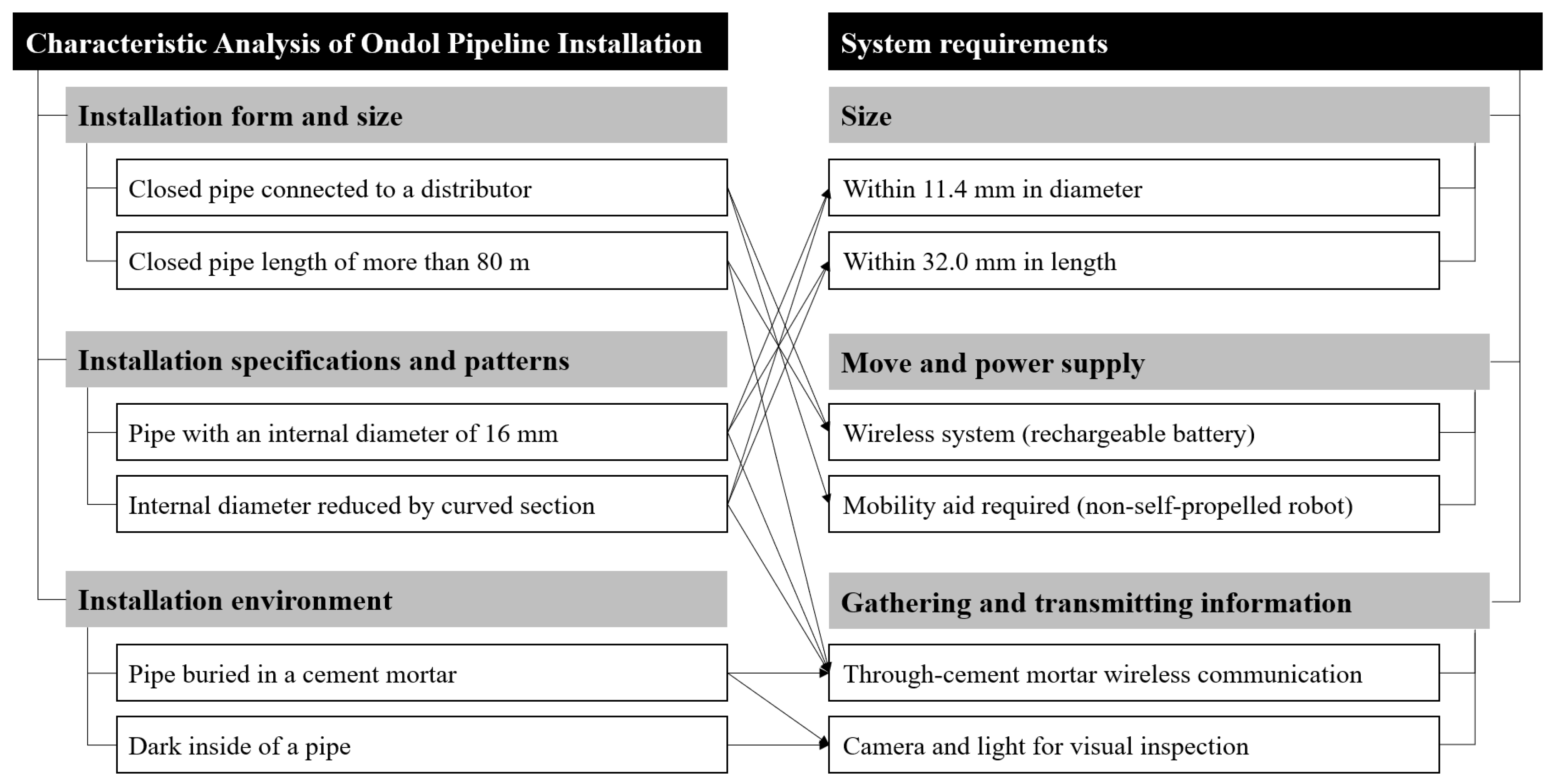
3.1. Subsection Characteristic Analysis of Ondol Pipeline Installation

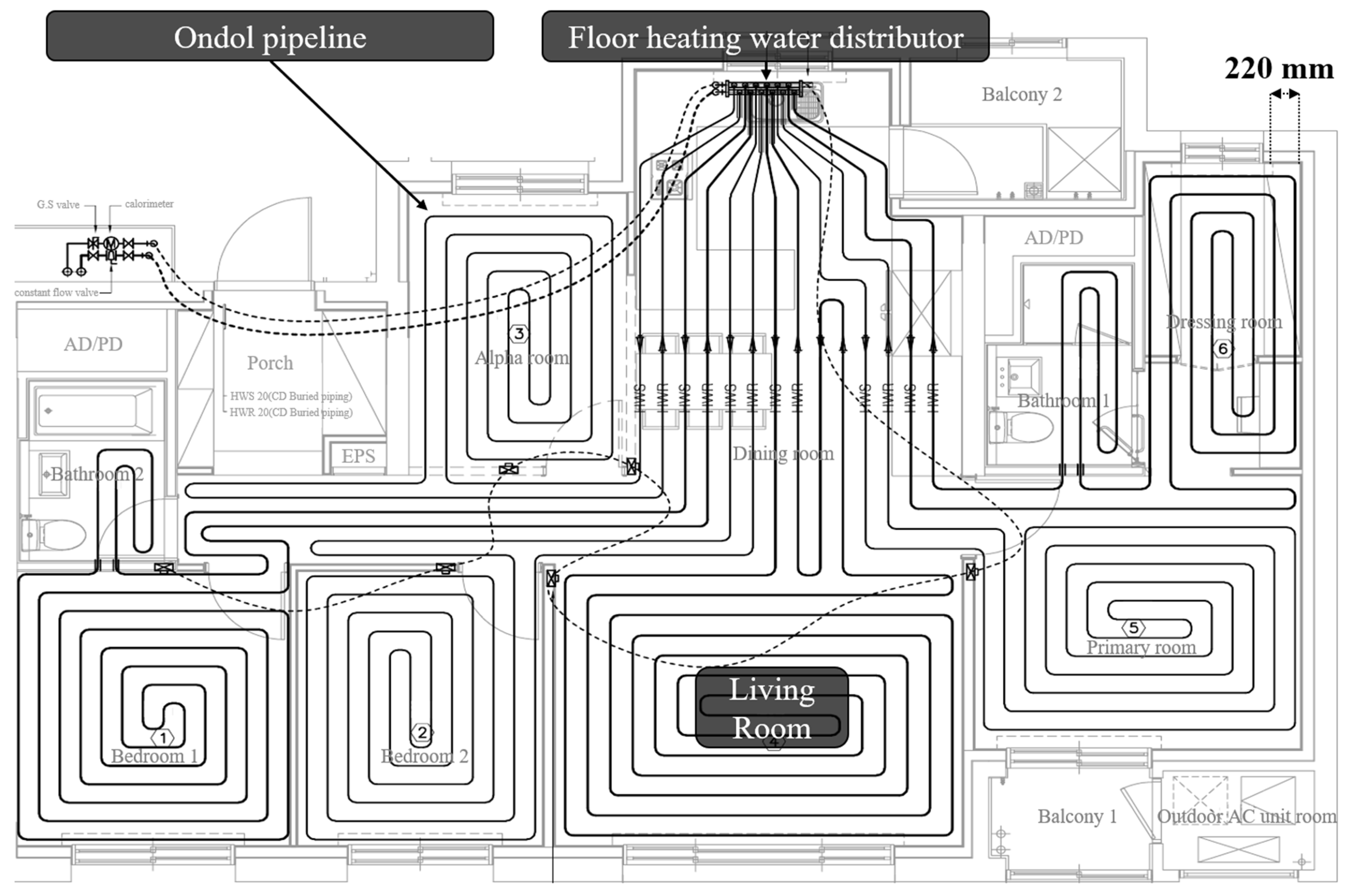
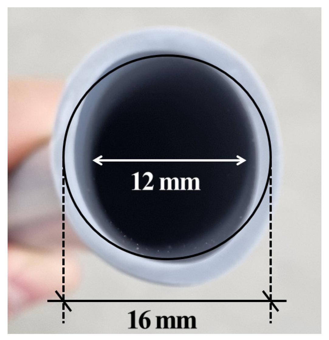
3.1.1. Installation Form and Size

An ondol piping system is an underfloor heating system where pipes are installed on the floor slab in a pattern of curves and straight lines. Figure 1 shows the heating pipe layout of an 84 m2 apartment, the most commonly constructed apartment type in South Korea. The pipes were connected to a distributor, laid in each room, and returned to the distributor. In such a sample layout, the longest pipe installed in the living room was 82 m long. The total length of all the pipes in the layout was ~397 m.
The ondol piping was embedded in cement mortar, and the starting and ending portions of the pipe network were connected to the distributor. Therefore, an inspection robot should be inserted at the connection between the distributor and piping, and it would travel through the piping and return to the distributor. For example, a robot inserted at the starting part of the distributor to inspect the living room piping would have to travel the 82 m-long living room piping and return to the distributor, resulting in a long travel distance. In the case of a wired robot, the cable should be longer than the travel distance. Such wired communications and power supplies can be inefficient for inspection. Therefore, inspection robots are required to enable wireless communication and use rechargeable batteries instead of power cable supplies. Additionally, as rechargeable batteries have limited capacity, equipping the robot with a self-propulsion system such as a motor can result in a short operation time and risk of loss. Thus, robots should be designed with a non-powered propulsion system, implying the need for auxiliary equipment to move the robot.

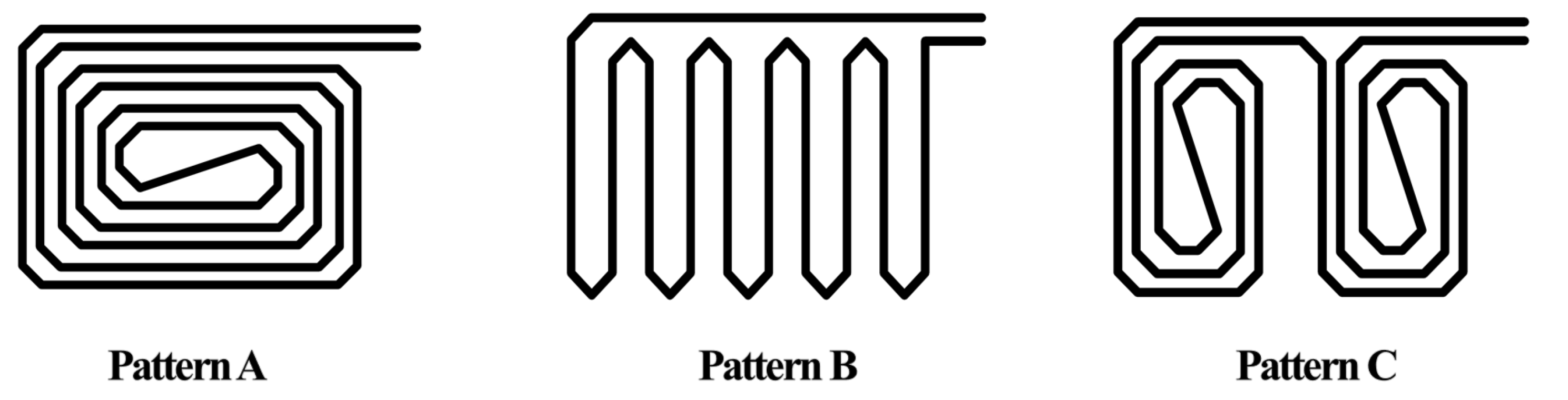
3.1.2. Installation Specifications and Patterns

Generally, ondol pipes have a thickness and inner diameter of 2 and 12–25 mm, respectively; however, pipes with an inner diameter of 16 mm are primarily used in ondol piping. Therefore, an inspection robot with a diameter of less than 16 mm must be developed. Additionally, the robot must pass through curved sections according to the installation patterns of the pipes. The representative patterns of the ondol pipeline are shown in Figure 2. Pattern A in Figure 2 is the same as that in Figure 1 and is the most common pattern. Depending on the size of the room, they can also be installed in the form of patterns B and C.
The curved sections in the pattern are important because the original circular cross-section of pipes changes to an elliptical shape in the curved section. Therefore, the horizontal diameter inside the pipe is smaller than that in the curved section. Figure 3 illustrates the situation in which the horizontal diameter of the cross-section decreases, dividing the sections of the pattern into straight, 90-degree rotation, and 180-degree rotation.
For example, in the case of a pipe with an inner diameter D, the inner diameter remains at D in the straight section. However, in a 90-degree curved section, the inner diameter of the pipe decreases to 95%, becoming 0.95D, and in the largest 180-degree section, it decreases to 75%, becoming 0.75D. Figure 4 shows an image of the cross-section of a 16 mm pipe in a 180-degree section that has been physically installed. The cross-section becomes elliptical, with a horizontal diameter of 12 mm. Although the vertical diameter is longer than 16 mm, the smallest diameter must be considered for the robot to pass through. Therefore, the robot must be designed to be smaller than 12 mm.
In the design of the robot, determining the size that can pass through the pipes is the most critical priority, which is a very important and fundamental requirement and has become the standard for determining the size of all components and the type of system applied to a robot. Incorrect determination of size can lead to serious trial and error. Therefore, a preliminary experiment was conducted to determine the size of the robot prior to its design. Figure 5a shows the dummy robot used for the test, while Figure 5b shows the piping used for the experiment. The piping with straight, 90-degree, and 180-degree sections was constructed in the same manner as in the actual installation, and dummy robots of various sizes were fabricated using 3D printing. A total of 65 dummies were designed with diameters ranging from 9 to 12 mm and lengths ranging from 26 to 34 mm, divided into approximately 0.1 mm increments. Starting with the smallest dummy, the dummies were repeatedly inserted into the pipe to determine the largest dummy size that could move smoothly. The test results determined that a robot with a diameter of 11.4 mm and a length of 32 mm or less was required.

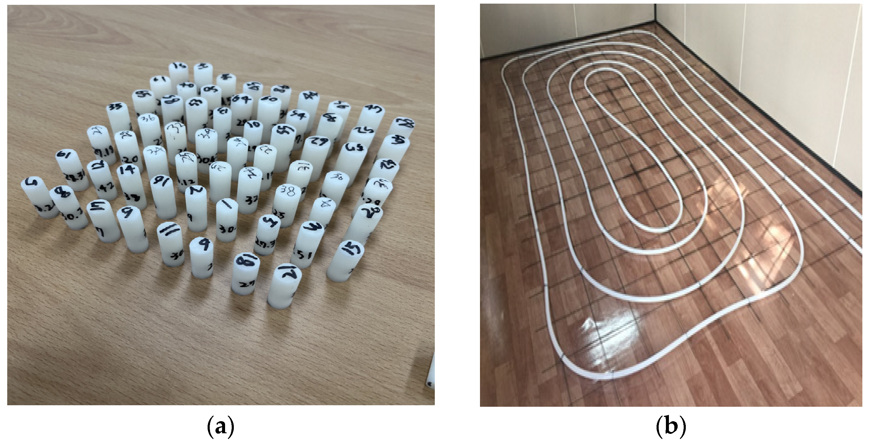
3.1.3. Installation Environment

The actual installation of the ondol piping is shown in Figure 6. Ondol piping and distributors are installed on the floor slab, and the thickness of the cement mortar is generally 20 mm. As aforementioned, the inserted robot was required to use a wireless communication system rather than a wired one, and the applied technology should enable smooth transmission and reception without being obstructed by the cement mortar covering the piping. In addition, as images were captured inside dark piping, a camera module and lighting that could respond to such an environment were required.

3.2. System Requirements and Design

The characteristics of the ondol pipes were analyzed for system design, and the results of deriving the system requirements are summarized in Figure 7.
As shown in the size section of the System Requirements section of Figure 7, the robot should be manufactured no larger than 11.4 mm in diameter and no larger than 32 mm in length. Additionally, the robot should function on a rechargeable battery with a wireless system and use auxiliary equipment for movement without self-driving capability. Since the ondol pipe is a closed structure in which an inlet and an outlet are connected in a distributor, we decided to use an air compression method that moves the robot by pushing air. The communication method was set through a preliminary study [6]. In this study, the communication capabilities of three wireless communication methods, namely Wi-Fi, Bluetooth, and radio frequency, embedded in cement mortar were tested, and Wi-Fi was found to be the most appropriate. Therefore, a Wi-Fi module was selected as the communication system. The most basic components included a camera module for video inspection inside the piping, LED lights, a charging port, and an on/off switch to control the power to the robot. Based on the requirements, the capsule-type piping inspection robot was designed. Figure 8 shows the configuration of the robot, which reflects the system requirements.

4. Development of Prototype and Performance Experiment

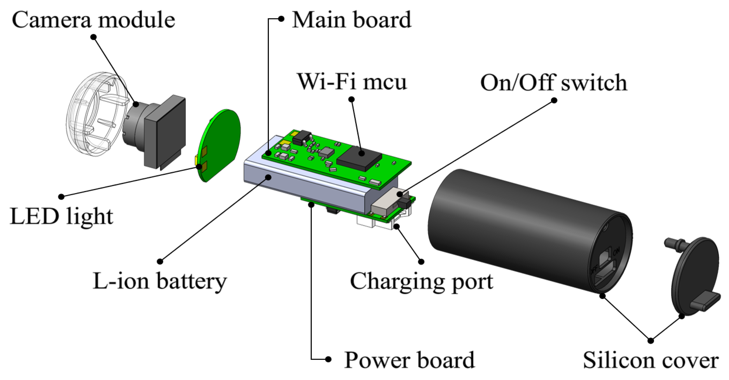
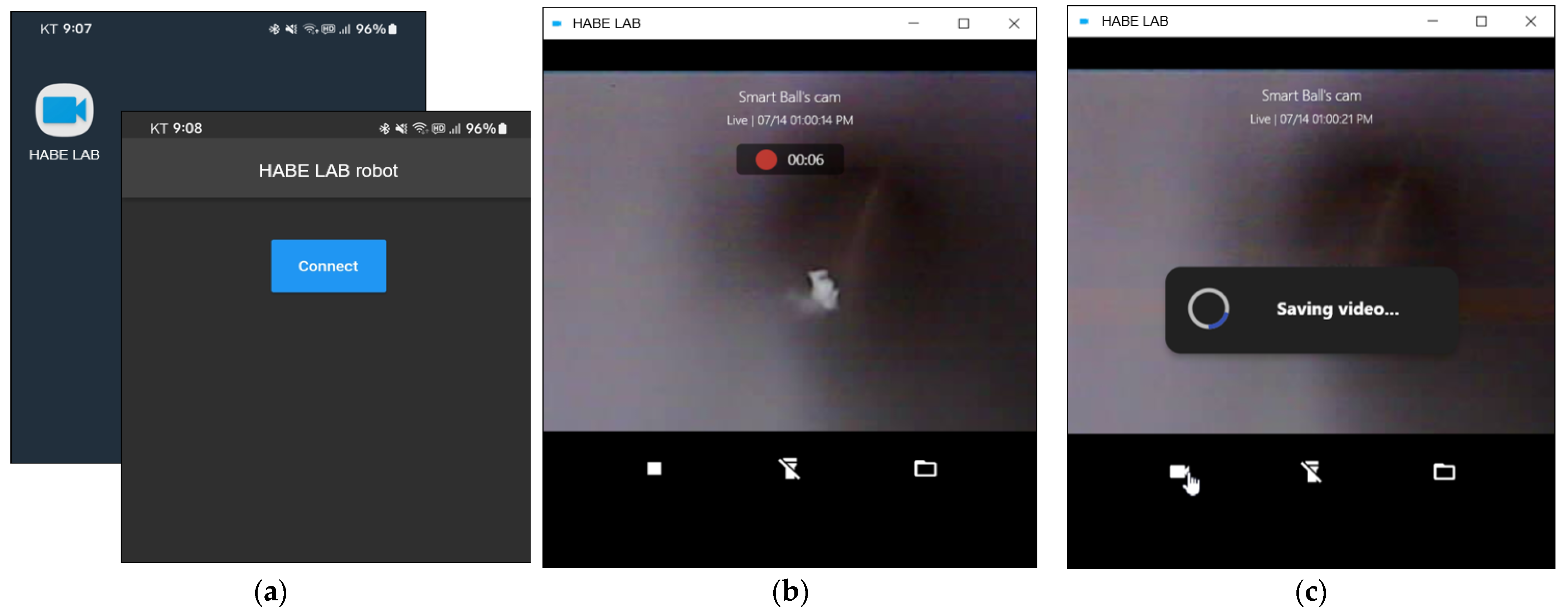
4.1. Prototype System

The inspection robot proposed for this study was designed to be inserted into a pipeline, moved inside by an air compressor, captured in real-time video, and transmitted to nearby monitoring equipment via wireless communication. Figure 9 shows the system requirements and appearance of the manufactured capsule-type inspection robot reflecting the aforementioned requirements. Figure 9a shows the prototype with the LED in the on/off state. Figure 9b shows the robot inserted into the pipeline, and Figure 9c shows an image verifying the size of the prototype using digital calipers. Considering the representative specifications of the detailed components, the robot was manufactured with a diameter and length of 11.34 mm and 31.92 mm, respectively. The camera had a resolution of 2 million pixels, and the battery was a rechargeable 3.7 V, 55 mAh lithium-ion type. The LED lighting included four LEDs with low power consumption and wide viewing angles, each with a maximum of 320 mcd. The Wi-Fi module operated at 2.4 GHz.
The video captured by the robot as it moved through the pipeline was transmitted in real time to the monitoring system via wireless communication. The system was developed as an application that could be installed on laptops, tablet PCs, and smartphones. The monitoring system comprised a viewer for the administrator to check the real-time video, a menu for recording and saving, and a function for turning the LED on the robot on and off. Figure 10 shows the operation of the application installed on a smartphone. As shown in Figure 10a, the administrator runs the application and connects it to the robot inserted into the pipeline. Figure 10b shows the robot moving inside the pipeline, transmitting real-time video to the smartphone, and recording it in the application. As shown in Figure 10c, the recorded video can be saved along a designated path.

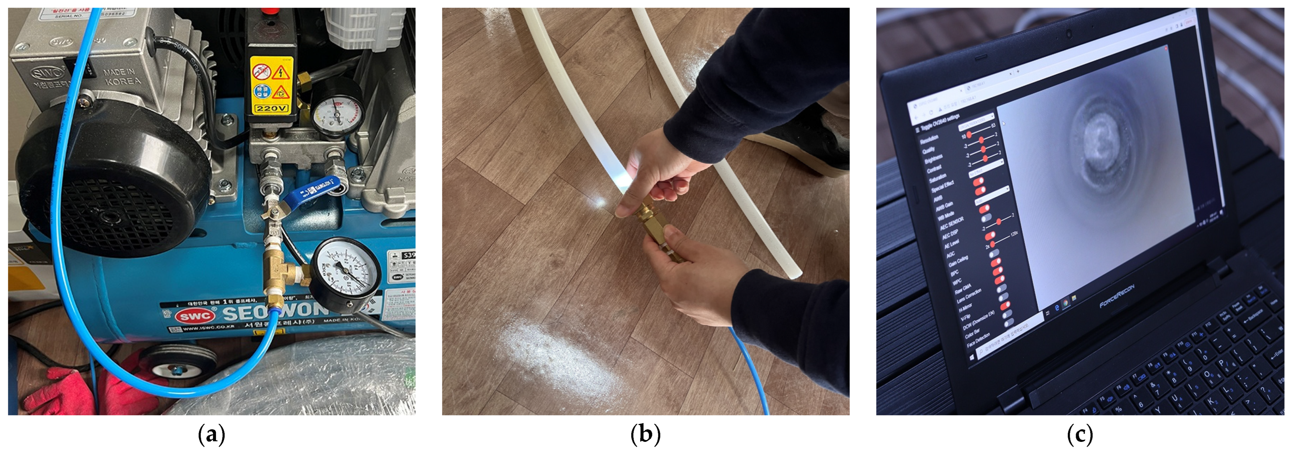
4.2. Performance Experiments

To verify the performance of the developed prototype system, a laboratory with ondol piping was constructed, and performance verification experiments were conducted. The laboratory constructed for the performance experiments is shown in Figure 11. The experiment was conducted identically for three patterns, as shown in Figure 2. To ensure field applicability of the developed system, the following verification was required: first, verification of smooth movement through the straight and curved sections of the piping; second, verification that the video captured by the robot was well transmitted in real time to the monitoring system and that defects were clearly identified by the naked eye on the monitoring system; and lastly, verification of the wireless communication performance. The verification of the communication performance was excluded from this experiment because the movement of the robot could not be visually confirmed when the piping was embedded in the cement mortar. The wireless communication performance had already been verified through preliminary research. Therefore, the performance verification focused on the mobility of the robot and the quality test of the detection screen of the monitoring system.
Figure 12 shows the process of inserting the robot into the piping. Figure 12a shows the air compressor used to move the inspection robot inside the piping. The air compressor used in this experiment was an off-the-shelf product with specifications of 3.5 Hp and 40 L. Figure 12b shows the process of inserting the inspection robot into the piping and connecting the air compressor hose to the piping. Figure 12c shows the monitoring system confirming the video sent by the inspection robot.
Figure 13 shows the movement of the inspection robot. The laboratory lights were turned off to confirm the moving position, and the LED on the robot was turned on. As shown in Figure 13a, the robot was brightly visible inside the pipe. Figure 13b,c show the curved and straight sections, respectively. The robot moved under the compressive force of the air introduced into the piping, and the moving speed was adjusted by the compressive force of the air compressor. In the experiment, the robot moved at an average speed of 350 mm/s with possible speed adjustments between 200 and 500 mm/s. Consequently, the robot was verified as moving smoothly in both straight and curved sections.
Figure 14 shows representative images of the video sent by the inspection robot while moving. Various situations that could occur during the actual installation were set up in the piping to verify whether they could be identified through the images captured by the robot. Figure 14a shows the normal interior of the piping. Figure 14b,c show the formation of wrinkles inside the piping due to bending beyond the elastic limit of the piping in the curved sections. The wrinkles occurred as a result of mistakes made by workers during the installation of the piping, which weakened the durability of the pipe wall, hindered the flow of hot water, and ultimately became a potential cause of leakage. Figure 14d shows pipe blockage. During the pipe installation, cement mortar and foreign substances could have entered, and the image showed such a situation. Figure 14e shows light leakage owing to damage at the pipe connection, and Figure 14f shows a hole created by a nail used to secure the piping during installation, which punctured the pipe wall due to a mistake by the worker.

4.3. Discussion and Further Study

The performance verification experiment confirmed that the developed robot could quickly navigate narrow inner diameters and curved sections of piping while maintaining sufficient video quality to identify issues. Given the nature of the ondol pipeline, it is crucial for the robot to move swiftly through the entire pipe without blockages and identify defects in the captured video rather than focusing on precise control of speed and movement. In other words, instead of implementing high-level technical solutions, the focus is on applying appropriate technology. The development of robots tailored to ondol pipeline inspection is considered meaningful. In this context, the validation of mobility and video quality suggests that the robot system proposed in this study is ready for immediate field deployment.
Several challenges were identified during the development and experimentation of the prototype. First, while the use of an air compressor for robot movement ensured adequate speed, it imposed limitations on the precise control of forward and backward movements. To address this issue, future work should focus on developing a segment-type robot by connecting two prototypes, thereby securing space for the drive unit and battery installation.
Furthermore, the current requirement for continuous visual inspection of the transmitted video from inside the piping reduced work efficiency. To enhance this aspect, future research should aim at transitioning to an artificial intelligence-based information-processing method that can automatically detect issues and incorporate notification and storage functions into monitoring systems.

5. Conclusions

In this study, an inspection robot system was developed to inspect ondol piping used for residential heating in Korea. The characteristics of the ondol piping were analyzed, and the performance requirements for the inspection robot system were derived based on the characteristics. A prototype was developed to satisfy the requirements, and experiments were conducted to verify whether the system achieved a performance level suitable for field applications.
Ondol piping is used for residential heating and embedded in cement mortar, leading to significant damage when repairs are necessary due to defects. Therefore, inspecting piping conditions during the installation stage is essential, and regular inspections are required during the maintenance stage. Korean apartments have numerous units, and the piping for inspection is extensive. The speed and accuracy of inspections are crucial requirements owing to the need for regular inspections during both the installation and maintenance stages. Existing ondol pipe inspection methods have limitations in responding to these requirements. Consequently, identifying issues within the ondol pipeline has emerged as a critical concern, highlighting the significance of this study in proposing a customized solution to address the inefficiencies inherent in existing inspection methods.
If this proposed system is applied in an actual application, visual confirmation can be attained for the construction quality of heating pipes that cannot currently be checked and facilitate the early detection of pipe deformation and damage, thereby eliminating potential defect factors. Furthermore, the system allows the accumulation of data related to ondol piping, which is used in most Korean residences, and minimizes labor and costs through non-destructive inspection technology. Ultimately, the proposed system is anticipated to reduce maintenance costs and extend the lifespan of buildings. This study can also aid the establishment of inspection systems for similar small-diameter pipes.

Author Contributions

Conceptualization, M.L. and U.-K.L.; methodology, M.L. and U.-K.L.; validation, U.-K.L.; formal analysis, M.L. and U.-K.L.; investigation, M.L. and U.-K.L.; resources, M.L. and U.-K.L.; data curation, M.L. and U.-K.L.; writing—original draft preparation, M.L. and U.-K.L.; writing—review and editing, M.L. and U.-K.L.; visualization, M.L. and U.-K.L.; supervision, U.-K.L.; project administration, U.-K.L.; funding acquisition, U.-K.L. All authors have read and agreed to the published version of the manuscript.

Funding

This research was supported by the Basic Science Research Program through the National Research Foundation of Korea (NRF), funded by the Ministry of Education (2020R1I1A3064165).

Institutional Review Board Statement

Not applicable.

Informed Consent Statement

Not applicable.

Data Availability Statement

The data presented in this study are available on request from the corresponding author. The data are not publicly available due to privacy.

Conflicts of Interest

The authors declare no conflicts of interest.

References

  1. Ambati, P.; Raj, K.M.; Joshuva, A. A review on pipeline inspection robot. AIP Conf. Proc. 2020, 2311, 060002. [Google Scholar]
  2. Jang, H.; Kim, T.Y.; Lee, Y.C.; Kim, Y.S.; Kim, J.; Lee, H.Y.; Choi, H.R. A review: Technological trends and development direction of pipeline robot systems. J. Intell. Robot. Syst. 2022, 105, 59. [Google Scholar] [CrossRef]
  3. John, B.; Shafeek, M. Pipe inspection robots: A review. IOP Conf. Ser. Mater. Sci. Eng. 2022, 1272, 012016. [Google Scholar] [CrossRef]
  4. Kim, S.K.; Lee, D.H.; Hong, H.K. An energy saving technique using ondol heating schedule control of housing units in Korea. Indoor Built Environ. 2010, 19, 88–93. [Google Scholar] [CrossRef]
  5. Lee, U.K. An experimental analysis of ultrasonic cavitation effect on ondol pipeline management. J. Korea Inst. Build. Constr. 2024, 24, 67–75. [Google Scholar]
  6. Jo, J.H.; Lee, U.K.; Jeong, J.H.; Lee, S.S. Comparatively testing concrete permeability for wireless communications of a pipe-cleaning robot. Int. J. Mech. Eng. 2022, 7, 0974–5823. [Google Scholar]
  7. Jo, H.J.; Lee, U.K.; Kim, J.Y.; Lee, S. Experiment on the feasibility of cleaning building pipelines using ultrasonic cavitation. In Proceedings of the 9th International Conference on Construction Engineering and Project Management, Las Vegas, NV, USA, 20–23 June 2022; pp. 295–303. [Google Scholar]
  8. Jeong, J.H.; Lee, S.S.; Lee, U.K. Design of ball-type equipment for pipeline maintenance. In Proceedings of the International Conference on Next-Generation Convergence Technology, Pusan, Republic of Korea, 11–12 January 2021. [Google Scholar]
  9. Elankavi, R.S.; Dinakaran, D.; Jose, J. Developments in in-pipe inspection robot: A review. J. Mech. Contin. Math. Sci. 2020, 15, 238–248. [Google Scholar]
  10. Ab Rashid, M.Z.; Yakub, M.F.M.; Bin Shaikh Salim, S.A.Z.; Mamat, N.; Putra, S.M.; Roslan, S.A. Modeling of the in-pipe inspection robot: A comprehensive review. Ocean Eng. 2020, 203, 107206. [Google Scholar] [CrossRef]
  11. Colvalkar, A.; Nagesh, P.; Sachin, S.; Patle, B.K. A comprehensive review on pipe inspection robots. Int. J. Mech. Eng. 2021, 10, 51–66. [Google Scholar]
  12. Elankavi, R.S.; Dinakaran, D.; Chetty, R.K.; Ramya, M.M.; Samuel, D.H. A review on wheeled type in-pipe inspection robot. Int. J. Mech. Eng. Robot. Res. 2022, 11, 745–754. [Google Scholar] [CrossRef]
  13. Rusu, C.; Tatar, M.O. Adapting mechanisms for in-pipe inspection robots: A review. Appl. Sci. 2022, 12, 6191. [Google Scholar] [CrossRef]
  14. Verma, A.; Kaiwart, A.; Dubey, N.D.; Naseer, F.; Pradhan, S. A review on various types of in-pipe inspection robot. Mater. Today Proc. 2022, 50, 1425–1434. [Google Scholar] [CrossRef]
  15. Kahnamouei, J.T.; Moallem, M. A comprehensive review of in-pipe robots. Ocean Eng. 2023, 277, 114260. [Google Scholar] [CrossRef]
  16. Ismail, I.N.; Anuar, A.; Sahari, K.S.M.; Baharuddin, M.Z.; Fairuz, M.; Jalal, A.; Saad, J.M. Development of in-pipe inspection robot: A review. In Proceedings of the 2012 IEEE Conference on Sustainable Utilization and Development in Engineering and Technology, Kuala Lumpur, Malaysia, 6–9 October 2012; pp. 310–315. [Google Scholar]
  17. Gargade, A.; Ohol, S. Development of in-pipe inspection robot. IOSR J. Mech. Civ. Eng. 2016, 13, 64–72. [Google Scholar] [CrossRef]
  18. Song, Z.; Luo, Y. Research status and development trend of oil and gas pipeline robot. Acad. J. Sci. Technol. 2022, 3, 134–140. [Google Scholar] [CrossRef]
  19. Mills, G.H.; Jackson, A.E.; Richardson, R.C. Advances in the inspection of unpiggable pipelines. Robotics 2017, 6, 36. [Google Scholar] [CrossRef]
  20. Roslin, N.S.; Anuar, A.; Jalal, M.F.A.; Sahari, K.S.M. A review: Hybrid locomotion of in-pipe inspection robot. Procedia Eng. 2012, 41, 1456–1462. [Google Scholar] [CrossRef]
  21. Blewitt, G.; Cheneler, D.; Andrew, J.; Monk, S. A review of worm-like pipe inspection robots: Research trends and challenges. Soft Sci. 2024, 4, 13. [Google Scholar] [CrossRef]
  22. Zhang, Y.; Yan, G. In-pipe inspection robot with active pipe-diameter adaptability and automatic tractive force adjusting. Mech. Mach. Theory 2007, 42, 1618–1631. [Google Scholar] [CrossRef]
  23. Hadi, A.; Hassani, A.; Alipour, K.; Askari Moghadam, R.; Pourakbarian Niaz, P. Developing an adaptable pipe inspection robot using shape memory alloy actuators. J. Intell. Mater. Syst. Struct. 2020, 31, 632–647. [Google Scholar] [CrossRef]
  24. Cetinsoy, E.; Esgin, H. Design of an ex-proof untethered in-pipe inspection robot. In Proceedings of the 2018 IEEE International Conference on Automation, Cluj-Napoca, Romania, 24–26 May 2018; pp. 1–6. [Google Scholar]
  25. Kwon, Y.S.; Lee, B.; Whang, I.C.; Kim, W.K.; Yi, B.J. A flat pipeline inspection robot with two wheel chains. In Proceedings of the 2011 IEEE International Conference on Robotics and Automation, Shanghai, China, 9–13 May 2011; pp. 5141–5146. [Google Scholar]
  26. Jalal, M.A.; Sahari, K.M.; Anuar, A. Development of magnetic wheeled boiler tube inspection robot. J. Teknol. 2015, 76, 19–23. [Google Scholar]
  27. Chatzigeorgiou, D.; Youcef-Toumi, K.; Ben-Mansour, R. Design of a novel in-pipe reliable leak detector. IEEE/ASME Trans. Mechatron. 2014, 20, 824–833. [Google Scholar] [CrossRef]
  28. Hirose, S.; Ohno, H.; Mitsui, T.; Suyama, K. Design of in-pipe inspection vehicles for φ25 φ50 φ150 pipes. In Proceedings of the 1999 IEEE International Conference on Robotics and Automation, Detroit, MI, USA, 10–15 May 1999; pp. 2309–2314. [Google Scholar]
  29. Elankavi, R.S.; Dinakaran, D.; Doss, A.S.A.; Chetty, R.K.; Ramya, M.M. Design and motion planning of a wheeled type pipeline inspection robot. J. Robot. Control 2022, 3, 415–430. [Google Scholar] [CrossRef]
  30. Zheng, D.; Tan, H.; Zhou, F. A Design of endoscopic imaging system for hyper long pipeline based on wheeled pipe robot. In Proceedings of the AIP Conference Proceedings, Wuhan, China, 25–26 February 2017. [Google Scholar]
  31. Li, H.; Li, R.; Zhang, J.; Zhang, P. Development of a pipeline inspection robot for the standard oil pipeline of china national petroleum corporation. Appl. Sci. 2020, 10, 2853. [Google Scholar] [CrossRef]
  32. Ariaratnam, S.T.; Chandrasekaran, M. Development of an innovative free-swimming device for detection of leaks in oil and gas pipelines. In Proceedings of the Construction Research Congress, Banff, AB, Canada, 8–10 May 2010; pp. 588–596. [Google Scholar]
  33. Chapman, H. Development of a successful internal leak detection and pipeline condition assessment technology for large diameter pipes. In Proceedings of the 6th Annual WIOA NSW Water Industry Engineers & Operators Conference, Tamworth, Australia, 27–29 March 2012; pp. 29–37. [Google Scholar]
  34. Islas-García, E.; Ceccarelli, M.; Tapia-Herrera, R.; Torres-SanMiguel, C.R. Pipeline inspection tests using a biomimetic robot. Biomimetics 2021, 6, 17. [Google Scholar] [CrossRef]
  35. Song, S.J. Development of the visual inspection device with driving motors for non-destructive test of piping from the inside. J. Korean Soc. Mech. Technol. 2018, 20, 541–547. [Google Scholar] [CrossRef]
Figure 1. Ondol pipeline system shown in the floor plan.
Applsci 14 07938 g001
Figure 2. Representative installation patterns of ondol pipeline.
Applsci 14 07938 g002
Figure 3. Change in internal diameter according to the bending angle of the pipeline.
Applsci 14 07938 g003
Figure 4. Internal diameter changes in the bending section.
Applsci 14 07938 g004
Figure 5. Experiment for determining robot size: (a) various sizes of robot dummies made by 3D printing; (b) pipeline installation for passage test of robot dummies.
Applsci 14 07938 g005
Figure 6. On-site installation of ondol pipeline.
Applsci 14 07938 g006
Figure 7. System requirements based on the characteristics of the ondol pipeline.
Applsci 14 07938 g007
Figure 8. Design of the ondol pipeline inspection robot reflecting the requirements.
Applsci 14 07938 g008
Figure 9. Prototype of the capsule-type pipeline inspection robot: (a) prototype; (b) prototype inserted into the pipeline; and (c) measuring the size of the prototype.
Applsci 14 07938 g009
Figure 10. Monitoring system application for pipeline inspection robot: (a) starting and connecting the application; (b) video captured inside the pipeline transmitted by the robot; (c) saving the video.
Applsci 14 07938 g010
Figure 11. Laboratory constructed according to the installation patterns of ondol pipeline.
Applsci 14 07938 g011
Figure 12. Starting the performance test: (a) air compressor used; (b) robot insertion; (c) monitoring system screen display.
Applsci 14 07938 g012
Figure 13. Movement of the robot inside the pipeline: (a) overall view of the pipeline; (b) curved section; and (c) straight section.
Applsci 14 07938 g013
Figure 14. Representative images transmitted by the robot: (a) normal condition of the pipeline; (b) wrinkled condition in the curved section; (c) wrinkled condition in the curved section; (d) blocked condition of the pipeline; (e) defect at the connection; (f) hole caused by a nail.
Applsci 14 07938 g014
Table 1. Existing studies proposing and developing pipeline inspection robots.
AuthorsPower SupplyDriving
Mechanism
UsePipe Size (mm)
Zhang and Yan (2007) [22]CableDiameter-adaptiveGas pipelines~400–600
Hadi et al. (2020) [23]CableDiameter-adaptivePipelines and duct~60–90
Cetinsoy and Esgin (2018) [24]BatteryDiameter-adaptiveGas pipelines~63–125
Kwon et al. (2011) [25]CableWheel-typeNot specified80–100
Jalal et al. (2015) [26]CableWheel-typeBoiler pipelines45
Chatzigeorgiou et al. (2014) [27]BatteryWheel-typeNot specified100
Hirose et al. (1999) [28]CableWheel-typeGas pipelines25, 50, 150
Elankavi et al. (2022) [29]CableWheel-typeNot specified~250–350
Zheng et al. (2017) [30]CableWheel-typeNot specified150
Li et al. (2020) [31]CableWheel-typeOil and gas pipelines~1219–1440
Ariaratnam and Chandrasekaran (2010) [32]BatteryBall-typeOil and gas pipelines300
Chapman (2012) [33]BatteryBall-typeWater pipelines300
Islas-García et al. (2021) [34]CableBug-typeDrainpipe76
Song (2018) [35]CableCrawler-typeNot specified~100–150
Disclaimer/Publisher’s Note: The statements, opinions and data contained in all publications are solely those of the individual author(s) and contributor(s) and not of MDPI and/or the editor(s). MDPI and/or the editor(s) disclaim responsibility for any injury to people or property resulting from any ideas, methods, instructions or products referred to in the content.

