Article

A High-Precision Active Vibration Isolation Control System: Experimental Study

1
Department of Intelligent Robot Engineering, Pukyong National University, Busan 48513, Republic of Korea
2
Department of Smart Mobility Engineering, College of Information Technology and Convergence, Pukyong National University, Busan 48513, Republic of Korea
*
Authors to whom correspondence should be addressed.
Appl. Sci. 2024, 14(17), 7966; https://doi.org/10.3390/app14177966
Submission received: 13 August 2024 / Revised: 1 September 2024 / Accepted: 3 September 2024 / Published: 6 September 2024
(This article belongs to the Section Robotics and Automation)

Abstract

:
Nowadays, the demand for high-precision devices is becoming more intense, thanks to the growing complexity and sophistication of modern technology and applications, including microscopy, nanomeasurement and analysis instruments. However, challenges arise because environmental factors such as vibration negatively affect their performance. An active vibration isolation system (AVIS) is one of the most recent solutions for that, but the high degree-of-freedom (DoF) nature results in it strongly suffering from unwanted interactions. Hence, in this paper, a robust decoupling controller is designed to handle the mentioned disadvantages. The system model is first presented, followed by the proposed decoupling techniques, and then, a feedback controller is designed by applying the mixed-sensitivity H control framework. Experimental studies are conducted to investigate the effectiveness of the proposed AVIS and compare it with other systems, namely, a passive vibration isolation system, a proportional–derivative (PD)-controlled AVIS, and a robust controlled AVIS. The robustness and decoupling performance of the proposed controller are guaranteed by suppressing external vibrations and isolating interactions, and, therefore, stabilizing the system.

1. Introduction

In recent decades, technology has made a great jump; hence, the demand for the accuracy of devices is much more intense. For instance, electron microscopy is applied to decipher nanoscale elementary processes by using very small electron beams, some of them around tens of nanometers in size. Therefore, even a modest vibration such as the ground vibration from other working devices can lead to blurring in the image and reduction in the effective spatial resolution [1]. Another significant disturbance is the vibration coming from the running of the devices themselves or from their operators. As a result, the higher the performance of these devices, the higher the restrictions applied to vibrations. However, vibrations are unavoidable, especially in the mechanical realm, as mentioned in the example above. Therefore, without vibration isolation, the objective of such electron microscopy, or in general high-precision devices, cannot be achieved [2,3].
Passive vibration isolation systems (PVISs) and active vibration isolation systems (AVISs) are the two general methods applied to deal with the effect of vibrations. For a PVIS, the three main components are the top platform, the base platform, and the vibration isolation structure. The top platform carries high-precision devices and provides a working environment for them. The base platform is the supporting platform, usually connected to the ground. The vibration isolation structure usually consists of mechanical elements such as springs and dampers inserted between the two platforms, connecting the two platforms. The vibration transmitted from the ground and the amplified oscillation within the system are eliminated by the springs and dampers, hence stabilizing the top platform. PVISs have the advantage of a straightforward structure, with a very low cost, and no energy consumption. However, PVISs also have disadvantages such as uncontrolled vibration isolation performance, and limited working frequency—they only achieve good performance in the high-frequency zone. Furthermore, in the zone of resonant frequency, the vibrations of the system are amplified, so only a small force can make the system oscillate with the maximum amplitude [4]. Hence, there is a need to develop a new vibration isolation system to overcome the disadvantage of the PVISs—that is the AVIS.
The AVIS has the advantage of securing vibration suppression performance in a large frequency range. To achieve this objective, the system utilizes sensors to collect the motion, actuators to regulate the motion, and a properly designed control algorithm. The motion sensor is usually classified into three types: displacement, velocity, and acceleration. Displacement and acceleration sensors are deployed in many studies such as in [5,6,7]. The acceleration sensor is easy to install without much emphasis on sensor placement and it has a high-frequency response. On the other hand, the displacement sensor has the upper hand on non-contact measurement [8] but suffers from high cost and susceptibility to environmental influences [9]. The velocity sensor has the advantages of being easy to install, low in cost, and high in sensitivity. Therefore, in this study, geophones are used to collect the motion of the system. Another major component in an AVIS is the actuator. A piezoelectric stack actuator [10] has the advantage of high force generation, quick response, and the least moving parts, but the disadvantages of high cost and being easily affected by the environment, so drift may appear. A pneumatic actuator [8] has a fast response but the generated force is small and the setup is often complex. A giant magnetostrictive actuator [10,11] has the upper hand in high output force and high displacement in high frequency; however, the high power loss and complex setup are the hold-backs of this actuator. The most popular actuator in AVISs is the linear voice coil motor (VCM) [12,13]. The VCM has the advantage of simple design, low cost, and good linearity. Although the VCM provides a smaller force than other actuators, the VCM is preferable for controlling the proposed AVIS in this study [14]. Finally, a control algorithm regulates these actuators using feedback from the sensors such that the top platform and its carried devices are isolated from the external vibrations.
However, the high degree-of-freedom (DoF) nature of AVISs creates a great control challenge. Additionally, to achieve the stabilization objective in six DoFs, an AVIS is usually an over-actuated system, as the number of actuators must be greater than the controlled DoF. This, in turn, seriously contributed to the problem of interactions between individual movements in the 6-DoF AVIS. Nevertheless, the control system design requires not only decoupling the interactions but also satisfying the vibration isolation performance of the system. Modal decomposition is a common method that is applied for this. In [6], the authors proposed a novel design of an AVIS, using Halbach magnet array VCM actuators. The motion sensor used in this research is the acceleration sensor. The modal decomposition technique was applied to decouple the coupled degrees in the system. The designed controller consisted of six single-input–single-output (SISO) proportional–integral–derivative (PID) controllers. The paper demonstrated the resulting isolation performance of the AVIS in the z -direction with three different payloads. Another study [15] proposed a robust control via frequency-shaped sliding mode control by employing modal decomposition to transfer a multi-input–multi-output (MIMO) control problem into individual SISO control problems. However, the results in both studies were discussed only in the z -direction; therefore, the interaction isolation performances were not clearly shown in their simulation and experiment results. In [12], the modal decomposition technique was deployed to achieve the decoupling performance where the interactions in the system structure were regarded as zero. Then, six composite nonlinear feedback (CNF) controllers were designed for each input–output pair of the 6-DoF AVIS. The actuators used in that study are VCMs, and the motion sensors are two different types of acceleration sensors. The CNF controllers resulted in a quicker response, better transmissibility in the case of no payload, and smaller overshoot compared with the PID-controlled system, but the interaction isolation performances of the controller were still not investigated. Another method is non-interacting control with a linear matrix inequality (LMI) approach, as shown in [16]. An integral-type servosystem was designed with the feedback matrix obtained via the LMI approach so that the performance of the non-interacting control was satisfied. Furthermore, in [17], a robust H framework-based controller was proposed and the interactions were treated as disturbances of the AVIS. The simulation results in both studies confirmed the effectiveness of the controller in both the response of the system and the interaction isolation, but no experiments were conducted. In addition to that, a controller with a notch filter was designed in [13], but the full 6-DoF performance was not evaluated yet.
In this study, a robust decoupling controller for the 6-DoF AVIS is proposed and evaluated. The control objective is to suppress the external vibrations, isolate the interactions, and, hence, stabilize the carrying system. To meet the stated objectives, a feedforward compensator is proposed to suppress the effect of interactions; then, the mixed-sensitivity H control framework is applied to design a feedback controller. The structure of the paper is as follows: the configuration of the AVIS and its mathematical model are presented in Section 2. The actuators used in this study are VCMs, and the motion sensor is the geophone. In Section 3, the decoupling process and the controller design are conducted. Continuously, in Section 4, the experimental results are used to verify the effectiveness of the proposed controller. In the end, Section 5 presents the conclusions of the research.

2. System Modeling

The schematic illustration of the controlled 6-DoF AVIS with its coordinates is introduced in Figure 1. The system consists of two platforms: the top platform and the base platform. The top and base platforms’ coordinates are defined as right-handed systems, in which the z -axis points upward, the x -axis is directed forward, and the positive y -axis is pointing right. Define O t as the origin of the top platform, located at the center of mass of the top platform. Hence, x t , y t , and z t are the three axes in the top platform. Similarly, O b is the origin and x b , y b , z b are the three axes in the base platform. The top platform is supported by four vertical coil springs at the four corners, connecting the top and base platform. The vibration from the working environment will be transferred through the base platform and springs to the top platform. The springs act as passive isolators, isolating the vibration affecting the top platform. However, due to the characteristics of the system, this passive vibration isolation performs well in the high-frequency region but does not have any effect in the low-frequency region. Hence, the actuators are inserted between the two platforms to deal with this problem. The system uses four vertical VCMs, Z 1 ,   Z 2 ,   Z 3 ,   Z 4 , to generate the forces F v z 1 , F v z 2 , F v z 3 and F v z 4 along the z t -axis. The two horizontal VCMs X 1 ,   X 2 generate the forces F v x 1 , F v x 2 along the x t -axis, and the two horizontal VCMs Y 1 ,   Y 2 operate along the y t -axis. Each VCM consists of two halves, one half is attached to the underside of the top platform, while the other half is attached to the base platform’s upper surface, and they move in conjunction with each other. The motion of the top platform is limited by the plate guides, hence, protecting the VCMs from collision in the case of non-control. The motion of the AVIS is collected by 11 geophones, in which eight sensors are used to collect the velocity of the top platform in three directions ( x t , y t , and z t ). The remaining three sensors are aimed at collecting the translational velocity from the base in three directions ( x b , y b , and z b ). In the top platform, four geophone sensors are installed vertically along the z t -axis, two geophone sensors are installed horizontally along the x t -axis, and the other two geophone sensors are along the y t -axis, as shown in Figure 1.
The state–space form of the system dynamics is obtained as follows [18]:
X ˙ = A X + B U v + D X b + F t , Y = C X
in which
  • X R 12 is the state vector containing the translational and rotational displacements and velocities of the top platform;
  • U v R 6 is the control input vector that contains the total of forces and torques in the corresponding 6-DoF;
  • Y R 6 is the output vector of the control system, which consists of the 6-DoF velocities;
  • X b R 12 is the vibration, i.e., all displacements and velocities, from the base platform;
  • F t R 6 contains the other disturbances acting directly on the top platform;
  • The coefficient matrices A ,   B ,   C and D are written as in [18].
Another point is that without the external vibrations and disturbances, the relationship between the transfer matrix and the state space of the system is described as [19]
G s = C s I A 1   B
and results in the following form:
G s = G 11 ( s ) 0 G 13 ( s ) 0 G 15 ( s ) 0 0 G 22 ( s ) 0 G 24 ( s ) 0 G 26 ( s ) G 31 ( s ) 0 G 33 ( s ) 0 G 35 ( s ) 0 0 G 42 ( s ) 0 G 44 ( s ) 0 G 46 ( s ) G 51 ( s ) 0 G 53 ( s ) 0 G 55 ( s ) 0 0 G 62 ( s ) 0 G 64 ( s ) 0 G 66 ( s )
In Equation (3), the transfer functions in the diagonal line, G i i ( s ) , ( i = 1 ~ 6 ) , describe the relationship between the velocity output in the ith direction and the force/torque input applied in the same direction. Both numerator and denominator are in the form of the Laplace transform. The remaining non-diagonal transfer functions G i n ( s ) , ( i = 1 ~ 6 ,   i n ) , are the transfer functions of the interferences within the system. Hence, the performance of the system is affected not only by the external vibrations and disturbances but also by those interferences.

3. Controller Design

The purpose of the controller for the 6-DoF AVIS is to stabilize the top platform and its carried payload by isolating the effects of external vibrations. To achieve this, a controller is required to regulate the eight actuators appropriately to the system state which is provided from the feedback of the eight motion sensors. However, Equation (3) shows that there are also interferences in the system. Therefore, to successfully design an effective, robust controller, the feedforward compensators are implemented to suppress the mutual interferences in this study, and the mixed-sensitivity H control design is applied to obtain a feedback control system.

3.1. Design of Feedforward Control

To begin with, let us consider a dynamical MIMO system whose transfer matrix contains the elements in the diagonal line only. One can see that in this system, each output is independently controlled by the corresponding input, or, in other words, the system is totally decoupled. Then, recall the AVIS model given in (3) and rewrite it as follows:
G s = G i i s H s , H s = I 6 × 6 + G i i s 1 G i n s
where I 6 × 6 is the identity matrix, [ G i i ( s ) ] is the matrix containing the transfer functions in the diagonal line of G ( s ) , and G i i s 1 G i n s is the matrix that the element at the ith row and nth column is G i i s 1 G i n s , ( i n ) . It is worth noting that Equation (4) exists only if G i i s 1 G i n s is an analytic function and proper for every i and n [19]. Subsequently, the system output can be obtained as follows:
Y s = G i i s U k s , U k s = H s U v s
Here, U k ( s ) is the control input for the totally decoupled system, i.e., [ G i i ( s ) ] . In other words, each DoF of the AVIS can be independently controlled once U k ( s ) is derived. Then, by an inverse of H s , if H s is invertible, the actuating forces and torques U v can be obtained from U k . From Equations (4) and (5), U v ( s ) can also be computed as follows:
U v s = U k s G i i s 1 G i n s U v s
where the last term on the right-hand side is obtained from a straightforward calculation as follows:
G i i s 1 G i n s U v s = G 11 s 1 G 13 s F z s + G 11 s 1 G 15 s M θ y s G 22 s 1 G 24 s M θ x s + G 22 s 1 G 26 s M θ z s G 33 s 1 G 31 s F x s + G 33 s 1 G 35 s M θ y s G 44 s 1 G 42 s F y s + G 44 s 1 G 46 s M θ z s G 55 s 1 G 51 s F x s + G 55 s 1 G 53 s F z s G 66 s 1 G 62 s F y s + G 66 s 1 G 64 s M θ x s
with U v = F v x F v y F v z M θ x M θ y M θ z T . In Equation (7), each row of the control input U v is the sum of the corresponding element in U k and two terms computed from two other inputs. Thus, the term in Equation (7) serves as a feedforward control action eliminating the mutual interferences among the system’s DoF.

3.2. Design of Robust Feedback Control

The control input U k of the totally decoupled system [ G i i ( s ) ] is designed in this section. In this case, the feedforward compensator compensates for the mutual interferences, but at the same time, together with the other disturbance F t and ground vibration X b , acts as an uncertainty factor affecting the decoupled system. As mentioned, the mixed-sensitivity H control is applied due to its efficiency and effectiveness in dealing with uncertainties in a high-order system. Figure 2 shows the configuration of the mixed-sensitivity H control for the 6-DoF AVIS and Equation (8) shows the corresponding feedback control law.
U k s = K s Y ( s )
where the controller matrix K s is obtained in the form of Equation (9):
K s = d i a g { K x ( s ) , K y ( s ) , K z ( s ) , K θ x ( s ) , K θ y ( s ) , K θ z ( s ) }
in which K j , j = x , y , z , θ x , θ y , θ z , are the controllers of the interference-free system. The mixed-sensitivity problem can be explained as finding the rational function controller K s ensuring the stabilization of the closed-loop system and minimizing its H norm defined by [20,21]:
W 1 s K ( s ) T s W 2 s S ( s ) W 3 s T s
In Equation (10), S s = I 6 × 6 + G i i s K s 1 is the sensitivity function and the complementary sensitivity function is given by T s = G i i s I 6 × 6 + G i i s K s 1 [20,21]. W 1 s , W 2 s , and W 3 ( s ) are weighting functions of the 6-DoF AVIS’s mixed-sensitivity H control. Those frequency-dependent weighting functions must be proper and analytic. They are given in the form of
W i s = d i a g { W i x s , W i y s , W i z s , W i θ x s , W i θ y s , W i θ z s }
in which i = 1 ~ 3 .
As discussed, using the feedforward compensators G i i s 1 G i n ( s ) U v ( s ) , mutual interferences among the AVIS’s DoF are ruled out. However, although the direct disturbance compensators help overcome the mutual interferences, those compensators also contribute to the disturbances affecting the system. Hence, the weighting function W 1 ( s ) is chosen to correspond to the control input U k ( s ) . The total disturbances are suppressed by the weighting function W 2 ( s ) . The weighting function W 3 ( s ) is chosen to correspond to the output of the system. The weighting functions are selected based on the system’s characteristics and the designer’s experience, and they must exceed the corresponding system’s maximum singular value. Finally, the control law of the 6-DoF AVIS is obtained from (6) and (8) as follows:
U v s = K s Y s G i i s 1 G i j s U v s

3.3. Computation of Actuating Signals and Measurement Outputs

The proposed 6-DoF AVIS is operated by four vertical actuators and four horizontal actuators, defined as U a = F v x 1 F v x 2 F v y 1 F v y 2 F v z 1 F v z 2 F v z 3 F v z 4 T , as mentioned before. However, the designed control input in Equation (12) is U v = F v x F v y F v z M θ x M θ y M θ z T , containing a total of six forces and torques in the corresponding six DoF. Therefore, the actual control forces for the eight actuators U a can be derived from U v by the following equations:
U a = B a + U v B a + = B a T B a B a T 1
where B a R 6 × 8   is the allocation matrix of the eight actuators and B a + is the right inverse of it. Similarly, the eight geophones attached to the top platform give the measured output vector Y m = x ˙ 1 t x ˙ 2 t y ˙ 1 t y ˙ 2 t z ˙ 1 t z ˙ 2 t z ˙ 3 t z ˙ 4 t T . With C m R 8 × 6 being the distribution matrix of these sensors, the output vector Y corresponding to 6-DoF motion can be obtained from Y m as follows:
Y = C m + Y m , C m + = C m T C m 1 C m T
B a and C m   are easily derived from the system configuration demonstrated in Figure 1.

4. Experimental Study

4.1. System Implementation

The implementation of the proposed control is summarized as follows:
  • The System Identification toolbox of Mathworks MATLAB is used to identify the system parameters such as the nominal stiffness and damping ratio of the springs. The system matrices are subsequently obtained.
  • The feedforward control law is formulated as in Section 3.1.
  • The weighting functions are obtained as in Appendix B and, then, the controller matrix K(s) is acquired by applying the function ‘mixsyn’ in MATLAB. The Model Reducer toolbox is used to reduce the order of the controllers. The balanced truncation method is applied (Hankel singular values) with a frequency range focused from 0.01 to 100 [Hz].
  • The parameters of the controlled AVIS are listed in Table 1 below.
The elements of the controller matrix K s are listed as follows:
K x = 412.3 s 3 + 6.156 × 10 4 s 2 + 1.64 × 10 5 s + 1.419 × 10 7   s 3 + 49.92 s 2 + 266.5   s + 9928 , K y = 317 s 3 + 5.805 × 10 4 s 2 + 1.35 × 10 5 s + 1.352 × 10 7 s 3 + 50.89 s 2 + 266.4 s + 1.021 × 10 4 , K z = 2970 s 6 + 8.538 × 10 5 s 5 + 1.476 × 10 8 s 4 + 1.699 × 10 10 s 3 + 1.097 × 10 12 s 2 + 4.36 × 10 13 s + 5.41 × 10 13 s 6 + 287.5 s 5 + 4.961 × 10 4 s 4 + 5.717 × 10 6 s 3 + 3.681 × 10 8 s 2 + 1.463 × 10 10 s + 1.76 × 10 10 , K φ x = 9.215 s 6 + 2812 s 5 + 6.907 × 10 5 s 4 + 6.943 × 10 7 s 3 + 7.107 × 10 9 s 2 + 2.954 × 10 11 s + 2.004 × 10 12 s 6 + 290.5 s 5 + 5.009 × 10 4 s 4 + 5.743 × 10 6 s 3 + 3.681 × 10 8 s 2 + 1.453 × 10 10 s + 1.734 × 10 10 , K φ y = 22.74 s 6 + 5.286 × 10 4 s 5 + 7.301 × 10 7 s 4 + 6.693 × 10 10 s 3 + 3.441 × 10 13 s 2 + 1.087 × 10 16 s + 1.074 × 10 17 s 6 + 2324 s 5 + 3.206 × 10 6 s 4 + 2.94 × 10 9 s 3 + 1.508 × 10 12 s 2 + 4.76 × 10 14 s + 4.545 × 10 15 , K φ z = 23.65 s 6 + 5.488 × 10 4 s 5 + 7.578 × 10 7 s 4 + 6.951 × 10 10 s 3 + 3.576 × 10 13 s 2 + 1.13 × 10 16 s + 1.116 × 10 17 s 6 + 2320 s 5 + 3.2 × 10 6 s 4 + 2.937 × 10 9 s 3 + 1.507 × 10 12 s 2 + 4.762 × 10 14 s + 4.555 × 10 15
In order to compare with the proposed control system, a proportional–derivative (PD) controller is also implemented for the AVIS. The PD control is chosen over the conventional PID for this vibration isolation problem thanks to the integral behavior of the springs in the system. An additional integral involves the velocity outputs along with their measurement noise and bias while it does not contribute to enhance the stability of the system. The PD controller has the form of
U v = d i a g { K P , K D } X ˙
K P and K D are the diagonal matrices of parameters of the PD controller for each DoF. The parameters are selected by a trial-and-error method with the assistance of the PID Tuner app in Mathworks MATLAB. They are listed as follows:
K P = d i a g 100 ,   80 ,   700 ,   10 ,   10 ,   10 , K D = d i a g { 0.3 ,   0.3 ,   0.3 ,   0.3 ,   0.3 ,   0.3 }
The system without control, i.e., PVIS, and the AVIS controlled only by the robust feedback control law U k are also taken into comparison.
The setup of the experiments is shown in Figure 3. The system consists of the AVIS (two platforms, mechanical springs, feedback sensors, actuators), amplifiers, data acquisition (DAQ), and the power source. The sensors, LGT Seismic Geophones 4.5 (LGT-4.5), are used to detect and measure the motion of the system. The actuators, VCMs, produce controlled movement. The amplifiers regulate the control signals sent from the DAQ device—dSPACE DS6101—to the actuator. The DAQ processes the data and then controls the actuators through the amplifiers. The amplifiers then drive the corresponding VCMs to produce the desired motions. The power source provides the energy needed to operate the system.

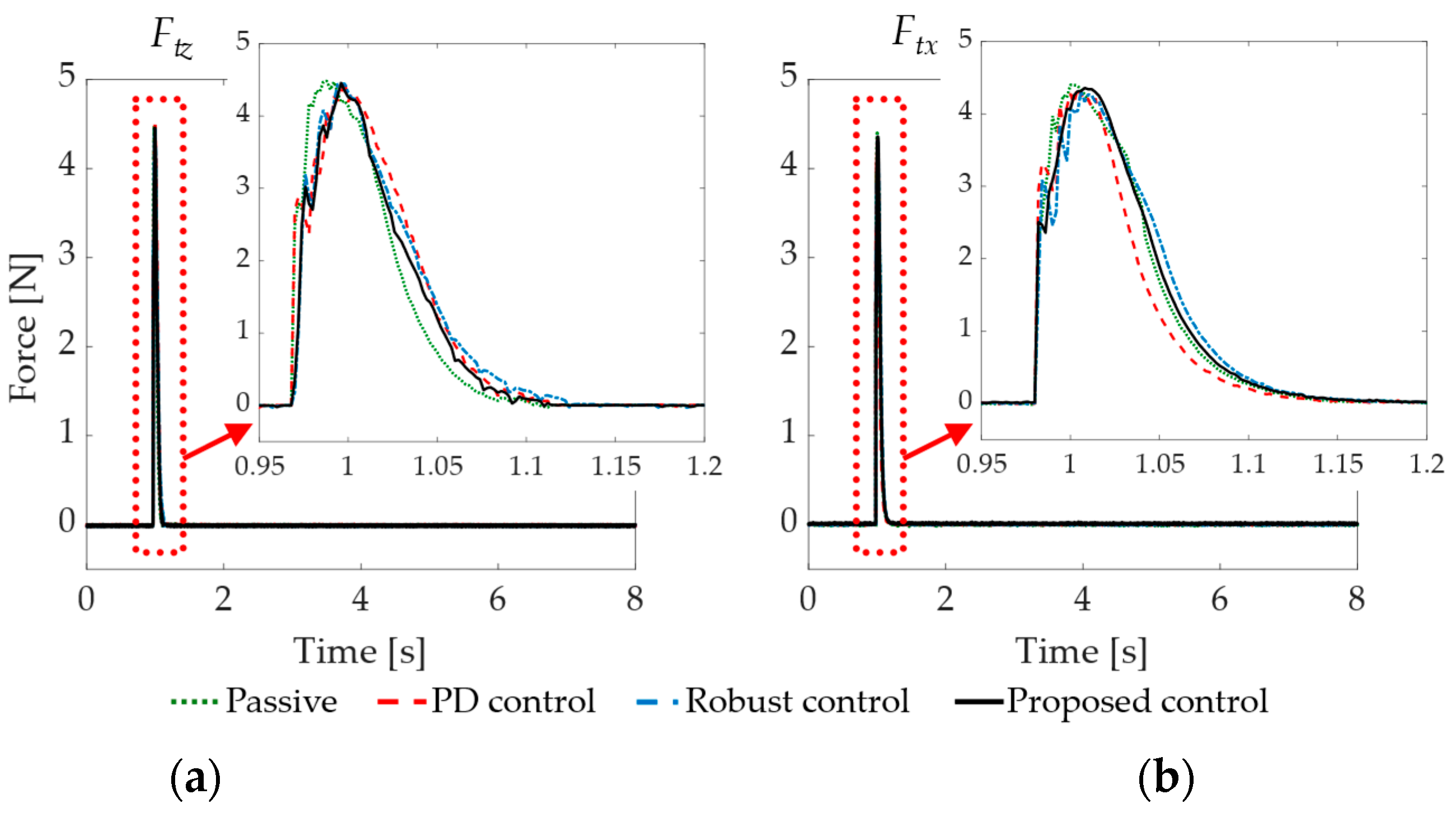
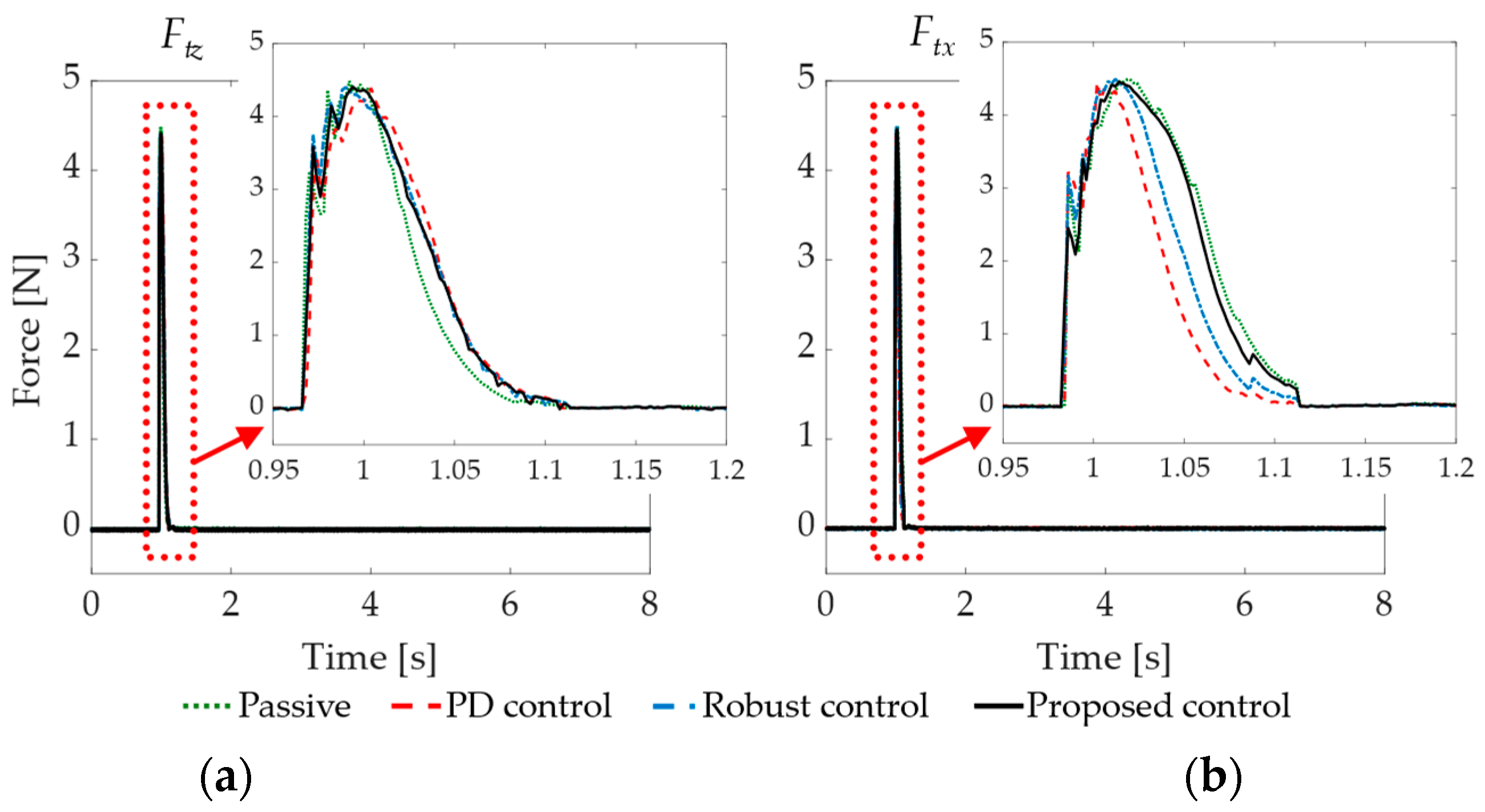
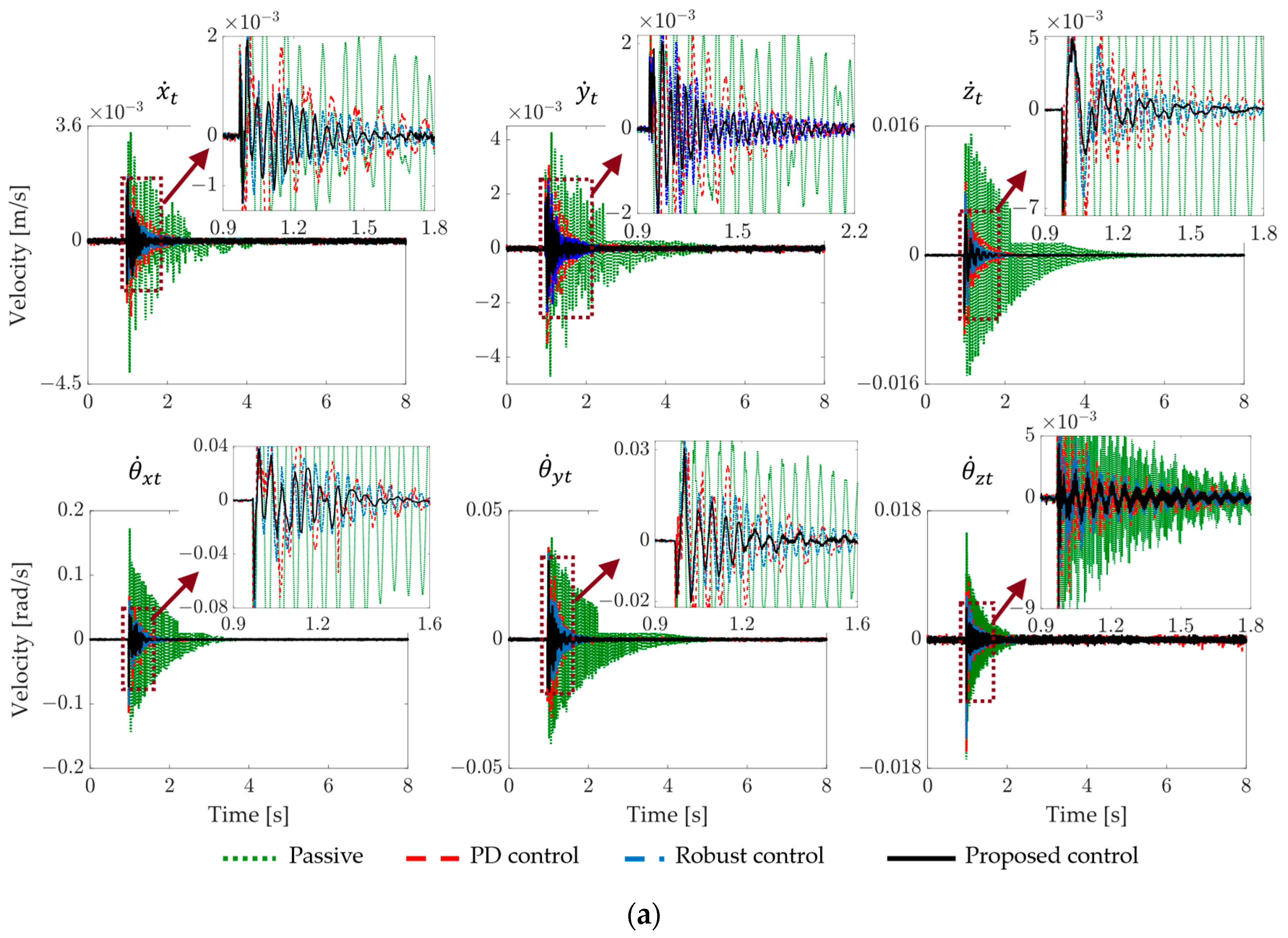
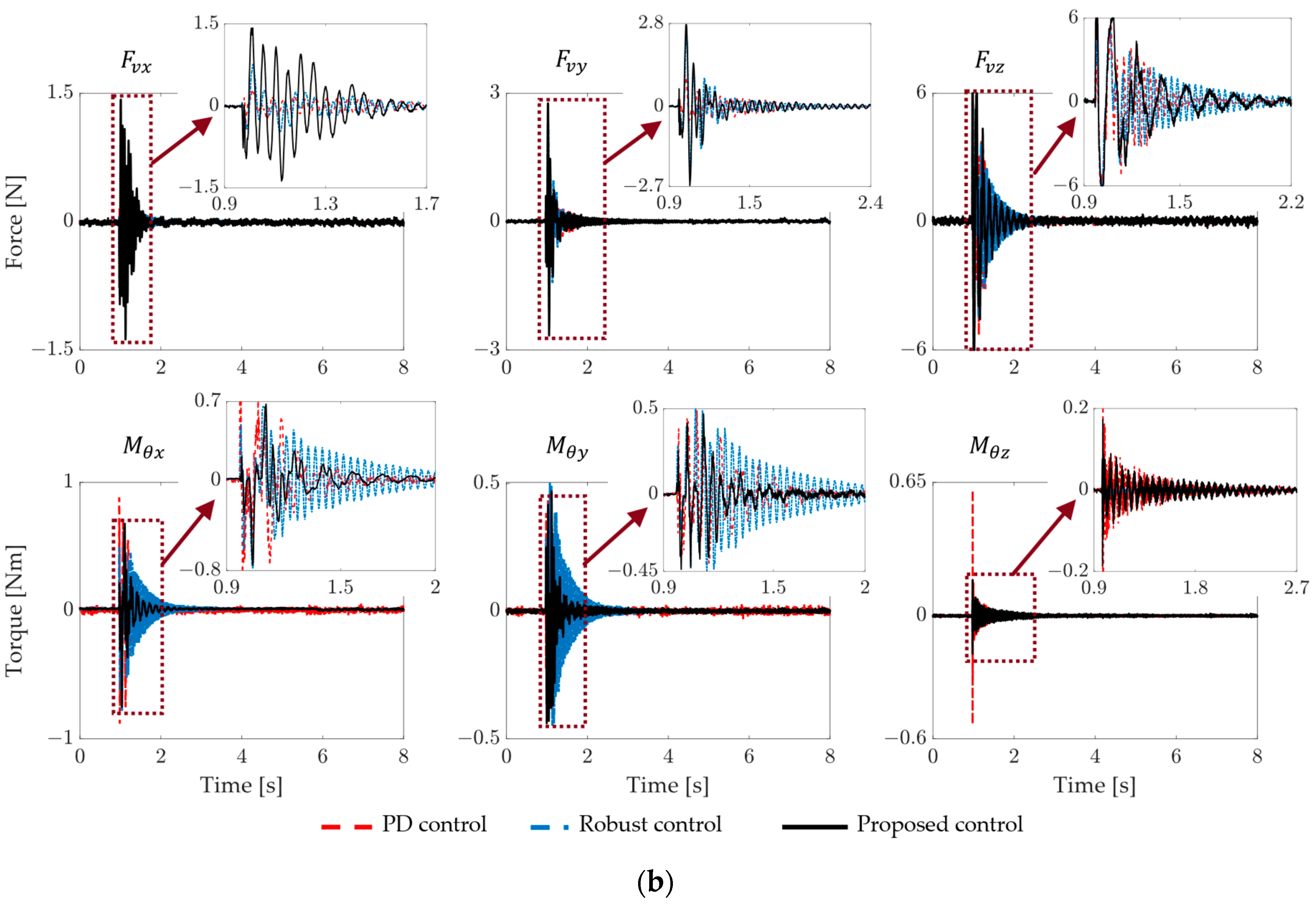
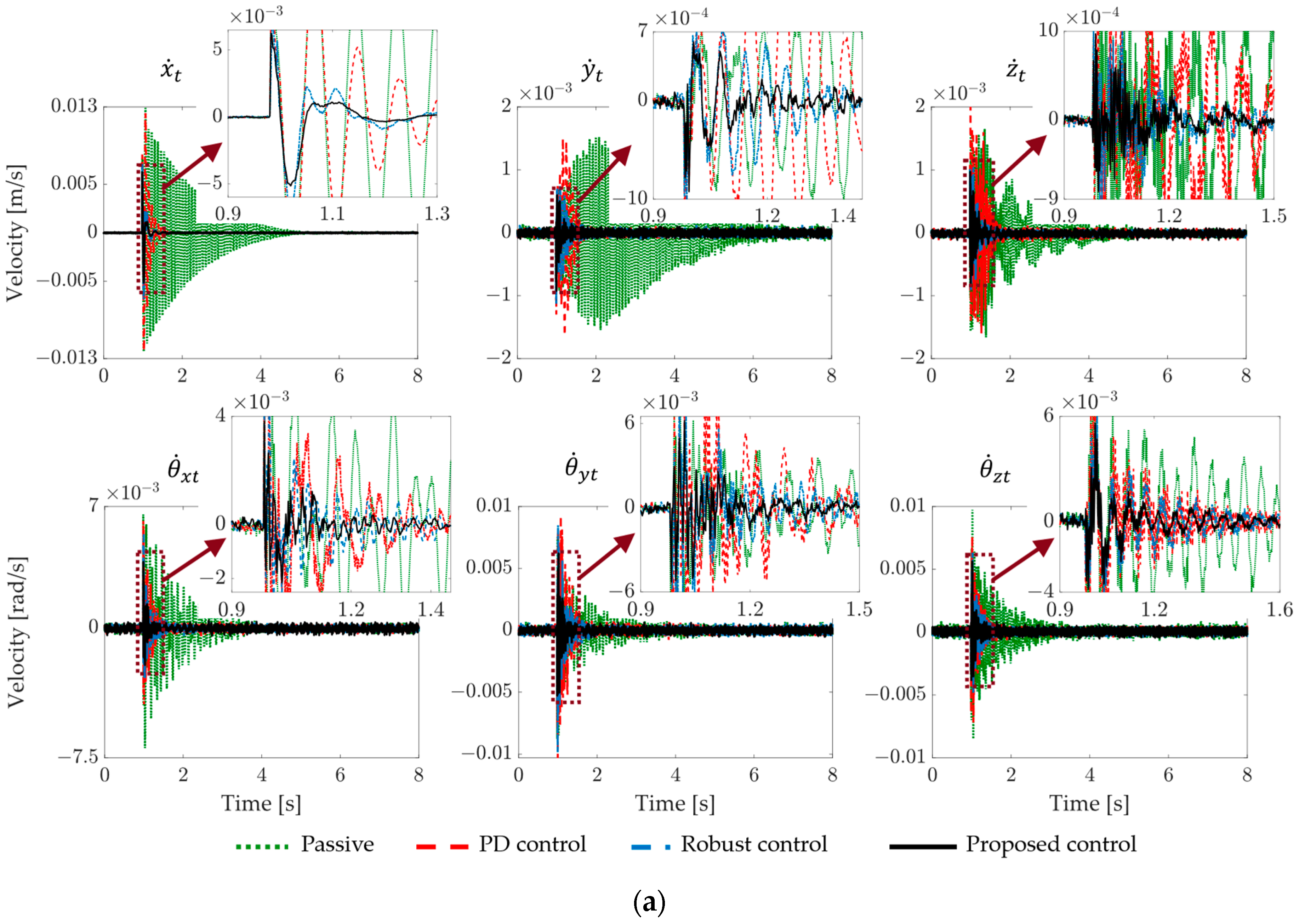
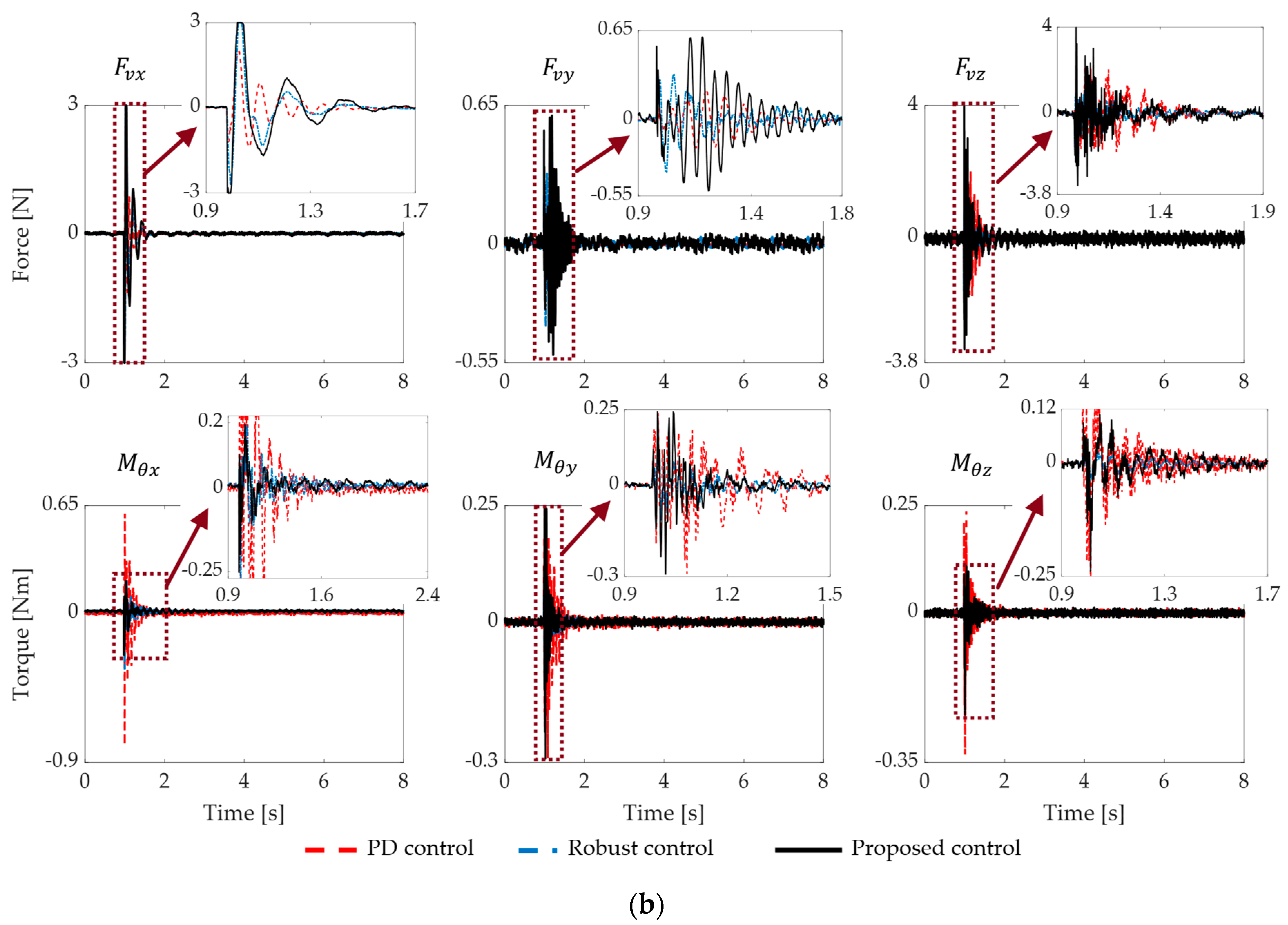
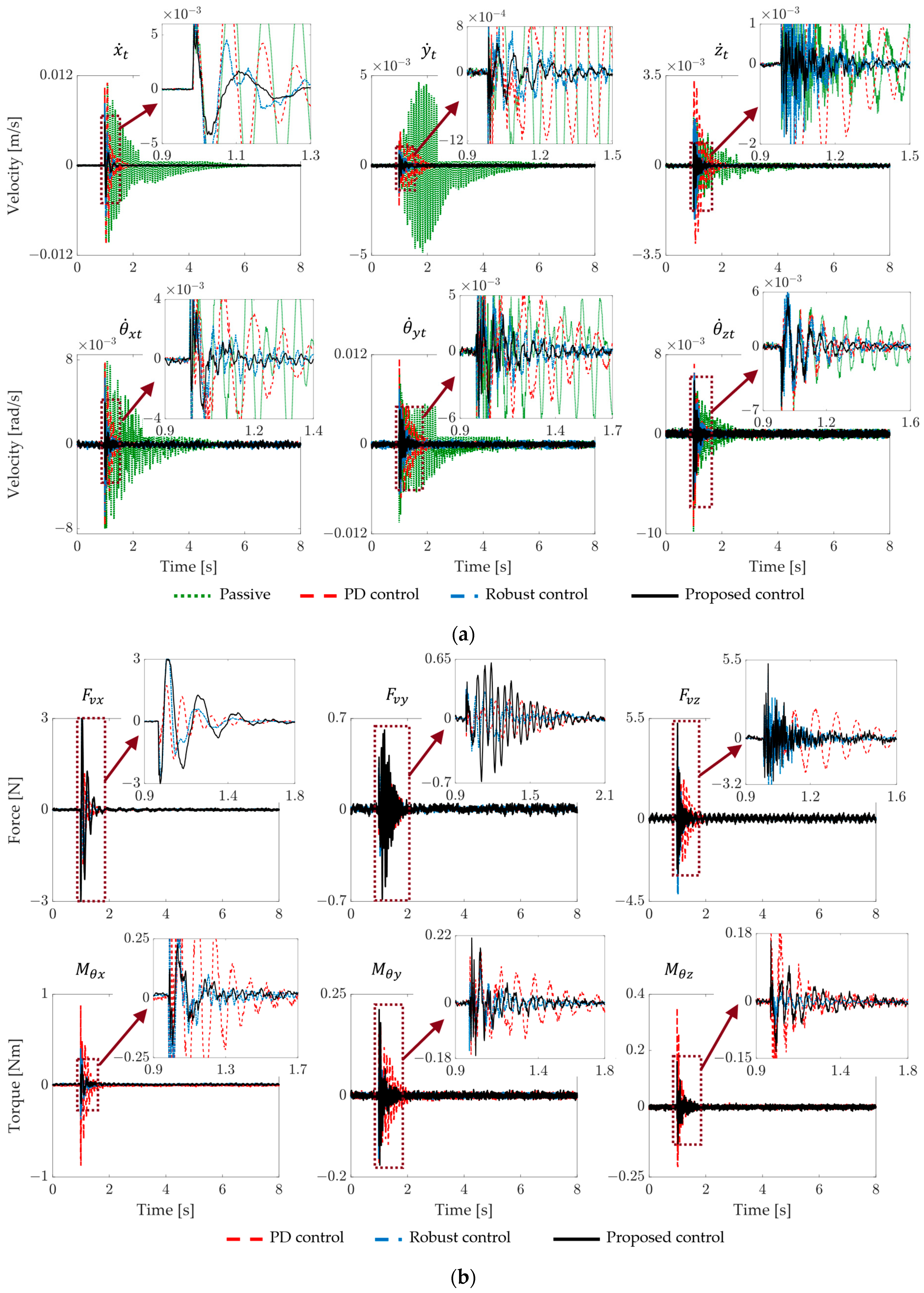
4.2. Experimental Results and Discussions

The experiments are conducted in four systems: the passive system, the AVIS with the PD controller, the AVIS with the robust feedback controller only, and the system with the proposed controller. Three scenarios are considered where an impact force is applied at a certain point in the top platform in the x t -, y t -, and z t -direction, respectively. Each scenario is conducted in two cases: with and without a 2.8 [kg] device mounted on the top platform. A loadcell CSBA-1LS is used to measure the impact force. Due to the similarity of the results in the x t - and y t -directions, only the former is shown in this paper. Figure 4 and Figure 5 show the impact forces in the x t - and z t -directions. The impact forces are approximately the same in each case and each scenario for valid comparisons.
Figure 6 shows the vibration suppression performances in the first case. An impact force is applied along the z t -direction to the top platform at 137.5 [mm] away from the right edge and 97.5 [mm] away from the rear edge. The peak force is about 4.5 [N], as seen in Figure 4. Such an eccentric vertical force will transmit three direct disturbances in the z t -, θ x t -, and θ y t -directions to the top platform. Of these, the motion in the z t -direction is most affected. This results in damped oscillations of the top platform if there is no control intervention. The results show that, in this passive system, the z t -direction motion needs about 5 [s] to reach the zero steady state again after the impact. With the operation of the VCMs, the proposed controller only needs 0.9 [s], whereas the robust controller and the PD controller need approximately 1.3 [s] and 1.5 [s]. The peak amplitude of the resulting velocity in the controlled cases is also smaller. The maximum is only 5 [mm/s] in the proposed AVIS compared to 7.7 [mm/s], 9 [mm/s], and 15 [mm/s] of the robust control, the PD control, and the passive system, respectively. However, in the other directions, the PD-controlled system has the least efficiency among the three, where the top platform’s oscillations last from the smallest 1.2 [s] ( θ ˙ x t ) to the largest 1.5 [s] ( θ ˙ z t ). The robust controller performs better since it only needs 0.9 [s] ( θ ˙ x t ) up to 1.3 [s] ( θ ˙ z t ). The most impressive of all is the robust decoupling controller, with mostly around 0.7 [s]. In terms of maximum amplitude, the PD controller has the least efficiency, from the smallest translational velocity of 2.4 [mm/s] ( x ˙ t ) to the largest rotational velocity of 0.07 [rad/s] ( θ ˙ x t ), while the robust controller is from 2.0 [mm/s] ( x ˙ t ) to 0.06 [rad/s] ( θ ˙ z t ). The most impressive is the robust decoupling controller, which is from 1.9 [mm/s] ( x ˙ t ) to 0.038 [rad/s] ( θ ˙ x t ). The control efforts in Figure 6b are the 6-DoF forces/torques computed from the eight actuators and show that the proposed controller reacts with the interactions better than the robust controller, and that the PD controller is the worst. In some cases, such as in the θ ˙ z t -direction, the PD controller requires the most torque but cannot maintain a good vibration suppression.
Figure 7 shows the performances in case of applying an impact force to the top platform without a payload in the x t -direction. The impact force is 37.5 [mm] away from the rear edge of the top platform and 8 [mm] below its top surface. This disturbs the top platform motion in the x t -, θ z t -, and θ y t -directions. The velocity of the x t -direction motion of the top platform in the passive case needs 5 [s] to reach the zero steady state. The proposed controller only needs 0.5 [s], whereas the robust controller and the PD controller need approximately 0.6 [s] and 0.7 [s], respectively. The amplitude of the top platform motion is also smaller in the cases of AVISs. The peak velocity of the proposed AVIS is only 5 [mm/s] compared to 7 [mm/s], 12 [mm/s], and 13 [mm/s] of the robust control, the PD control, and the passive system, respectively. The resulting motions of the top platform in the other directions show a similar trend to those in the first experimental case. That is, the PD control system is the worst among the AVISs, in both terms of settling time and peak velocity. On the other hand, the proposed control system suppresses the vibration the most effectively. The control efforts show that the proposed controller reacts with the interactions within the system better than the robust controller, and the PD controller is the worst. In some cases, such as in the θ ˙ z t - and θ ˙ x t -direction, the PD controller has the most torque but still can not maintain a good vibration suppression performance.
In summary, the experimental results in Figure 6 and Figure 7 indicate that all considered controllers are efficient in isolating the vibration for the top platform of the system. They provide significantly better results in comparison to the passive system, i.e., the one without a controller. Moreover, the proposed robust decoupling controller proves to be superior to the other controllers, not only in the direction of the disturbance vibrations but also in all other directions. That is, the proposed system attains the best performance in terms of vibration isolation and mutual interference compensation.
The results from the two other experimental cases are shown in Figure 8 and Figure 9. In these cases, a device weighing 2.8 [kg] is mounted on the top platform, thus acting as a payload. The impact forces depicted in Figure 5 and the points of impact are as same as in the first two experiments. One can easily see that, for the passive system, the peak velocities are much smaller, and the settling times are much longer than those in the first two experiments, even though the impact forces are roughly the same in all situations. This is due to the payload leading to the increment of the total mass of the oscillating system, resulting in a smaller amplitude and lower natural frequency. The control performances show a similar trend to the cases without a payload. That is, the PD-controlled system is the worst, then the robust control without the feedforward compensators, and the proposed controlled system is the most effective one. Especially, the performance of the PD-based AVIS becomes significantly worse in the loaded cases compared with the unloaded cases. For example, in the third experiment, the passive system needs 6.5 [s] to settle the vertical vibration. The proposed controller only needs 0.9 [s], whereas the robust controller and the PD controller need approximately 1.4 [s] and 1.6 [s]. The amplitude of the motion in the PD-controlled system is initially smaller than in the passive one, then increases and remains at a notable width before completely settling at 1.6 [s].
The worsened performance indicates that the PD-controlled system is easily affected by uncertainties, i.e., the payload in this case. The robust control system and the proposed AVIS, on the other hand, provide consistent execution where the proposed one once again shows its superiority in every direction of the top platform motion. Corresponding to the resulting motions, the VCMs in the PD-controlled system are usually required to operate the most. The control inputs of the proposed controller, on the contrary, often manipulate the actuator for only a short period but provide the most effective vibration isolation and interaction compensation.

5. Conclusions

This paper presents the design and evaluation of the robust decoupling controller for the 6-DoF AVIS. The controller ensures the stabilization of the top platform of the AVIS by isolating the external vibrations and compensating the mutual interferences among its DoF. The control strategy integrates a feedback control law based on the mixed-sensitive H   framework with feedforward compensators to achieve the required performance. The experimental results, involving instant impacts from multiple directions, indicate that the proposed AVIS consistently delivers effective performance. When compared with the passive system and the systems controlled by other controllers, the proposed robust decoupling system is the best in both isolating the external disturbances and suppressing the interactions; therefore, the system is stabilized. Future work will include further experimental studies to assess performance under base platform vibrations and across a broader frequency range. Although the proposed controller provides an impressive performance, the design process was complex. Therefore, the development of a more compact controller will be explored to enhance feasibility.

Author Contributions

Conceptualization, Y.-B.K.; methodology, Y.-B.K., D.-H.L. and T.H.; software, T.-N.N.; validation, Y.-B.K., D.-H.L. and T.H.; formal analysis, T.-N.N.; investigation, T.H.; resources, Y.-B.K. and D.-H.L.; data curation, T.-N.N.; writing—original draft preparation, T.-N.N.; writing—review and editing, T.H.; visualization, T.-N.N.; supervision, Y.-B.K.; project administration, Y.-B.K.; funding acquisition, Y.-B.K. All authors have read and agreed to the published version of the manuscript.

Funding

This work was supported by the National Research Foundation (NRF), South Korea, under project BK21 FOUR (Smart Robot Convergence and Application Education Research Center). This work was also supported by the National Research Foundation of Korea (NRF) grant funded by the Korean government (MSIT) (No. 2022R1A2C1003486).

Institutional Review Board Statement

Not applicable.

Informed Consent Statement

Not applicable.

Data Availability Statement

The original contributions presented in the study are included in the article, further inquiries can be directed to the corresponding authors.

Conflicts of Interest

The authors declare no conflicts of interest. The funders had no role in the design of the study; in the collection, analyses, or interpretation of data; in the writing of the manuscript; or in the decision to publish the results.

Appendix A

Equation (4) can be generally rewritten as follows [19]:
H s = G ^ c s p s + I 6 × 6
in which G ^ c s p s represents the transfer function matrix G i i s 1 G i n s .
The matrix G ^ c s p s is the strictly proper part of the proper rational transfer matrix H s R 6 × 6 , G ^ c s p s contains the set of transfer functions G i i s 1 G i n s . The least common denominator of G ^ c s p s is given as
d c s = s k + α c 1 s k 1 + + α c k 1 s + α c k , G ^ c s p s = 1 d c s N c 1 s k 1 + N c 2 s k 2 + + N c k 1 s + N c k
where G ^ c s p s R 6 × 6 , α c k are the coefficiency of the least common denominator, N c k are 6 × 6 constant matrices, and k = 1 ~ 6 .
Equation (A1) can be expressed as follows [19]:
X ˙ H = α c 1 I p × p α c 2 I p × p α c k 1 I p × p α c k I p × p I p × p 0 p × p 0 p × p 0 p × p 0 p × p I p × p 0 p × p 0 p × p 0 p × p 0 p × p 0 p × p 0 p × p 0 p × p 0 p × p I p × p 0 p × p A H X H + I p × p 0 p × p 0 p × p 0 p × p B H U H , Y H = N c 1 N c 2 N c k 1 N c k C H X H + I p × p D H U H
in which A H R k p × k p , B H R k p × p , C H R q × k p , p = q = 6 .
A matrix V H is defined as follows:
V H = A H B H C H D H
An element n is defined as n = d e t V H ¯ i 1 , i 2 , , i n k 1 , k 2 , , k n = d e t D H . One can see, n is the determinant of the identity matrix I 6 × 6 . Because d e t I 6 × 6 = 1 , n is non-zero. According to Theorem 1 in [22], H s = I 6 × 6 + G i i s 1 G i n s is invertible.

Appendix B

The weighting function matrices W i ( s ) are listed below.
W 1 x = 17.83 s 2 + 2395 s + 2898 s 2 + 1564 s + 4.316 × 10 4 , W 1 x = 17.83   s 2 + 2395   s + 2898 s 2 + 1564   s + 4.316 e 04 ,
W 2 x = 0.837 s 3 + 190.6 s 2 + 69140 s + 1.048 × 10 6 s 3 + 147.6 s 2 + 8137 s + 880700 , W 2 x = 0.837   s 3 + 190.6   s 2 + 69140   s + 1.048 e 06 s 3 + 147.6   s 2 + 8137   s + 880700 ,
W 3 x = 0.06983 s 2 + 4.316 s + 110 s 2 + 14.42 s + 4868 , W 3 x = 0.06983   s 2 + 4.316   s + 110 s 2 + 14.42   s + 4868 ,
W 1 y = 18.77 s 2 + 2521 s + 3051 s 2 + 1646 s + 4.543 × 10 4 , W 1 y = 18.77 s 2 + 2521 s + 3051 s 2 + 1646 s + 4.543 e 04 ,
W 2 y = 0.3171 s 3 + 1373 s 2 + 8.162 × 10 5 s + 2.063 × 10 5 s 3 + 239.6 s 2 + 1.041 × 10 4 s + 1378 , W 2 y = 0.3171 s 3 + 1373 s 2 + 8.162 e 05 s + 2.063 e 05 s 3 + 239.6 s 2 + 1.041 e 04 s + 1378 ,
W 3 y = 0.6185 s 2 + 18.18 s + 7.165 s 2 + 5.347 s + 0.1798 , W 3 y = 0.6185   s 2 + 18.18   s + 7.165 s 2 + 5.347   s + 0.1798 ,
W 1 z =   16.89 s 2 + 2269 s + 2746 s 2 + 1498 s + 4.134 × 10 4 , W 1 z =   16.89   s 2 + 2269 s + 2746 s 2 + 1498 s + 4.134 e 04 ,
W 2 z = 0.3347 s 4 + 1.344 s 3 + 2698 s 2 + 412 s + 43.9 s 4 + 0.3316 s 3 + 5.805 s 2 + 0.0813 s + 0.07904 , W 2 z = 0.3347   s 4 + 1.344   s 3 + 2698   s 2 + 412   s + 43.9 s 4 + 0.3316   s 3 + 5.805   s 2 + 0.0813   s + 0.07904 ,
W 3 z = 0.0878 s 3 + 55.35 s 2 + 4.439 × 10 4 s + 6644 s 3 + 108.4 s 2 + 9260 s + 1422 , W 3 z = 0.0878 s 3 + 55.35 s 2 + 4.439 e 04 s + 6644 s 3 + 108.4 s 2 + 9260 s + 1422 ,
W 1 θ x = 18.02 s 2 + 2420 s + 2929 s 2 + 1580 s + 4.361 × 10 4 , W 1 θ x = 18.02   s 2 + 2420   s + 2929 s 2 + 1580   s + 4.361 e 04 ,
W 2 θ x = 0.3012 s 4 + 1.21 s 3 + 2428 s 2 + 370.8 s + 39.51 s 4 + 0.2984 s 3 + 5.224 s 2 + 0.07317 s + 0.0711 , W 2 θ x = 0.3012   s 4 + 1.21   s 3 + 2428   s 2 + 370.8   s + 39.51 s 4 + 0.2984   s 3 + 5.224   s 2 + 0.07317   s + 0.0711 ,
W 3 θ x = 0.6061 s 2 + 17.82 s + 7.022 s 2 + 5.24 s + 0.1762 , W 3 θ x = 0.6061   s 2 + 17.82   s + 7.022 s 2 + 5.24   s + 0.1762 ,
W 1 θ y = 17.64 s 2 + 2370 s + 2868 s 2 + 1547 s + 4.27 × 10 4 , W 1 θ y = 17.64   s 2 + 2370   s + 2868 s 2 + 1547   s + 4.27 e 04 ,
W 2 θ y = 0.4096 s 4 + 345.6 s 3 + 300600 s 2 + 1.427 × 10 6 s + 729700 s 4 + 187.1 s 3 + 35810 s 2 + 137200 s + 68190 , W 2 θ y = 0.4096   s 4 + 345.6   s 3 + 300600   s 2 + 1.427 e 06   s + 729700 s 4 + 187.1   s 3 + 35810   s 2 + 137200   s + 68190 ,
W 3 θ y = 0.5938 s 2 + 17.45 s + 6.878 s 2 + 5.133 s + 0.1726 , W 3 θ y = 0.5938   s ^ 2 + 17.45   s + 6.878 s ^ 2 + 5.133   s + 0.1726 ,
W 1 θ z = 0.052 s 2 + 3037 s + 4.912 × 10 6 s 2 + 12.33 s + 13890 , W 1 θ z = 0.052 s 2 + 3037 s + 4.912 e 06 s 2 + 12.33 s + 13890 ,
W 2 θ z = 0.3686 s 4 + 311 s 3 + 270540 s 2 + 1.284 × 10 6 s + 656730 s 4 + 168.4 s 3 + 32229 s 2 + 123480 s + 61371 W 2 θ z = 0.3686   s 4 + 311   s 3 + 270540   s 2 + 1.284 e 06   s + 656730 s 4 + 168.4   s 3 + 32229   s 2 + 123480   s + 61371
W 3 θ z = 0.005 s 2 + 3.73 s + 9514 s 2 + 10.94 s + 14430 W 3 θ z = 0.005 s 2 + 3.73 s + 9514 s 2 + 10.94 s + 14430

References

  1. Picher, M.; Mazzucco, S.; Blankenship, S.; Sharma, R. Vibrational and optical spectroscopies integrated with environmental transmission electron microscopy. Ultramicroscopy 2015, 150, 10–15. [Google Scholar] [CrossRef] [PubMed]
  2. Inman, D.J. Vibration with Control, 2nd ed.; John Wiley & Sons: New York, NY, USA, 2017; ISBN 978-1119108214. [Google Scholar]
  3. Preumont, A. Vibration Control of Active Structures, 4th ed.; Springer Nature Switzerland AG: Cham, Switzerland, 2018; Volume 246, ISBN 9789400720329. [Google Scholar]
  4. Landau, I.D.; Airimitoaie, T.; Castellanos-Silva, A.; Constantinescu, A. Adaptive and Robust Active Vibration Control: Methodology and Tests (Advances in Industrial Control); Springer Nature Switzerland AG: Cham, Switzerland, 2017. [Google Scholar]
  5. Sun, J.O.; Kim, K.J. Six-degree of freedom active pneumatic table based on time delay control technique. Proc. Inst. Mech. Eng. Part I J. Syst. Control Eng. 2012, 226, 622–637. [Google Scholar] [CrossRef]
  6. Kim, M.H.; Kim, H.Y.; Kim, H.C.; Ahn, D.; Gweon, D.G. Design and control of a 6-dof active vibration isolation system using a halbach magnet array. IEEE/ASME Trans. Mechatron. 2016, 21, 2185–2196. [Google Scholar] [CrossRef]
  7. Wu, W.; Chen, X.; Shan, Y. Analysis and experiment of a vibration isolator using a novel magnetic spring with negative stiffness. J. Sound Vib. 2014, 333, 2958–2970. [Google Scholar] [CrossRef]
  8. Zhang, P. Advanced Industrial Control Technology; Elsevier: Amsterdam, The Netherlands, 2010. [Google Scholar]
  9. Yang, Y.; Yang, B. Displacement sensor with nanometric resolution based on magnetoelectric effect. IEEE Sens. J. 2021, 21, 12084–12091. [Google Scholar] [CrossRef]
  10. Gao, J.X.; Cheng, L. Modelling of a high performance piezoelectric actuator assembly for active and passive vibration control. Smart Mater. Struct. 2004, 13, 384–392. [Google Scholar] [CrossRef]
  11. Claeyssen, F.; Lhermet, N.; Maillard, T. Magnetostrictive actuators compared to piezoelectric actuators. In European Workshop on Smart Structures in Engineering and Technology; SPIE: San Francisco, CA, USA, 2003; pp. 194–200. [Google Scholar]
  12. Jiang, D.; Li, J.; Li, X.; Deng, C.; Liu, P. Modeling identification and control of a 6-dof active vibration isolation system driving by voice coil motors with a halbach array magnet. J. Mech. Sci. Technol. 2020, 34, 617–630. [Google Scholar] [CrossRef]
  13. Chen, Y.D.; Fuh, C.C.; Tung, P.C. Application of voice coil motors in active dynamic vibration absorbers. IEEE Trans. Magn. 2005, 41, 1149–1154. [Google Scholar] [CrossRef]
  14. Kim, M.; Kim, H.; Gweon, D.G. Design and optimization of voice coil actuator for six degree of freedom active vibration isolation system using halbach magnet array. Rev. Sci. Instrum. 2012, 83, 105117. [Google Scholar] [CrossRef] [PubMed]
  15. Zuo, L.; Slotine, J.J.E. Robust vibration isolation via frequency-shaped sliding control and modal decomposition. J. Sound Vib. 2005, 285, 1123–1149. [Google Scholar] [CrossRef]
  16. Lee, D.H.; Kim, Y.B.; Chakir, S.; Huynh, T.; Park, H.C. Noninteracting control design for 6-dof active vibration isolation table with lmi approach. Appl. Sci. 2021, 11, 7693. [Google Scholar] [CrossRef]
  17. Kim, H.J.; Lee, D.H.; Park, H.C.; Kim, Y.B. Direct disturbance suppression system design for high precision fabrication tables. Trans. Korean Soc. Mech. Eng. A 2020, 44, 843–853. [Google Scholar] [CrossRef]
  18. Nguyen, T.-N.; Huynh, T.; Lee, D.-H.; Kim, Y.-B. Design of robust decoupling controller for 6-dof active vibration isolation system. J. Power Syst. Eng. 2024, 28, 21–32. [Google Scholar] [CrossRef]
  19. Chen, C.-T. Linear System Theory and Design: International, 4th ed.; Oxford University Press: Oxford, UK, 2013; ISBN 978-0199964543. [Google Scholar]
  20. Zhou, K.; Doyle, J. C Essentials of Robust Control; Prentice Hall: Upper Saddle River, NJ, USA, 1998; p. 425. [Google Scholar]
  21. Scherer, C.W. Theory of Robust Control; Delft University of Technology: Delft, The Netherlands, 2001. [Google Scholar]
  22. Dorato, P. On the inverse of linear dynamical systems. IEEE Trans. Syst. Sci. Cybern. 1969, 5, 43–48. [Google Scholar] [CrossRef]
Figure 1. Configuration of the 6-DoF AVIS. (a) Exploded-view drawing; (b) top view of the AVIS top platform with its dimensions and coordinates; (c) front and side views of the AVIS; (d) top view of the AVIS base platform with its coordinates.
Applsci 14 07966 g001
Figure 2. Schematic drawing of the proposed control with fictitious weighted outputs.
Applsci 14 07966 g002
Figure 3. Experiment setup.
Applsci 14 07966 g003
Figure 4. Impact forces in experimental cases with no payload. (a) Case 1: impact force in the z t -direction; (b) case 2: impact force in the x t -direction.
Applsci 14 07966 g004
Figure 5. Impact forces in experiment cases with payload. (a) Case 3: impact force in the z t -direction; (b) case 4: impact force in the x t -direction.
Applsci 14 07966 g005
Figure 6. Experimental results in case 1: (a) velocities at the center of the top platform; (b) control efforts.
Applsci 14 07966 g006aApplsci 14 07966 g006b
Figure 7. Experimental results in case 2: (a) velocities at the center of the top platform; (b) control efforts.
Applsci 14 07966 g007aApplsci 14 07966 g007b
Figure 8. Experimental results in case 3: (a) velocities at the center of the top platform; (b) control efforts.
Applsci 14 07966 g008
Figure 9. Experimental results in case 4: (a) velocities at the center of the top platform; (b) control efforts.
Applsci 14 07966 g009
Table 1. Parameters of the 6-DoF AVIS.
ParameterDescriptionUnitValue
Mechanical componentsmTotal mass of the top platformkg9.085
J θ x ,     J θ y ,     J θ z   Moment of inertia of the top platform kg·m20.1218, 0.1656, 0.2838
l , w , h Length, width, and height of the top platformmm465, 366, 12
k x ,   k y ,   k z Identified stiffness of the spring N/m12683, 12683, 22526.2
c x ,   c y ,   c z Identified damping ratio of the springNs/m9.087, 9.087, 26.64
l z Vertical   distance   from   O t to the top surfacemm1.5
l x i ,   l y i Distance   from   spring   i , (   i = 1 ~ 4 )   to   O t   in   the   x t -   and   y t -directions mm161.3, 161.3, 170.7, 170.7,
215.5, 215.5, 215.5, 215.5
VCMs l v z x i ,   l v z y i Distance   from   VCM   Z i , (   i = 1 ~ 4 )   to   O t   in   the   x t -   and   y t -directionsmm146.7, 146.7, 156.3, 156.3,
146.6, 146.6, 146.6, 146.6
l v x x i ,   l v x y i ,   l v x z i Distance   from   VCM   X i , (   i = 1 ~ 2 )   to   O t   in   the   x t - ,   y t -   and   z t -directionsmm69.8, 69.8,
199.9, 199.9,
13.4, 13.4
l v y x i ,   l v y y i ,   l v y z i Distance   from   VCM   Y i , (   i = 1 ~ 2 )   to   O t   in   the   x t - ,   y t -   and   z t -directionsmm145.8, 155.2,
0, 0,
13.4, 13.4
Geophones l g z x i ,   l g z y i ,   l g z z i Distance   from   sensor   Z i , (   i = 1 ~ 4 )   to   O t   in   the   x t - ,   y t -   and   z t -directionsmm151.3, 151.3, 160.7, 160.7,
112.9, 112.9, 112.9, 112.9
20.9, 20.9, 20.9, 20.9,
l g x x i ,   l g x y i ,   l g x z i Distance   from   sensor   X i , (   i = 1 ~ 2 )   to   O t   in   the   x t - ,   y t -   and   z t -directionsmm70.3, 70.3,
137.4, 137.4,
11.3, 11.3
l g y x i ,   l g y y i ,   l g y z i Distance   from   sensor   Y i , (   i = 1 ~ 2 )   to   O t   in   the   x t - ,   y t -   and   z t -directionsmm109.3, 118.7,
53.1, 52.8,
11.3, 11.3
Disclaimer/Publisher’s Note: The statements, opinions and data contained in all publications are solely those of the individual author(s) and contributor(s) and not of MDPI and/or the editor(s). MDPI and/or the editor(s) disclaim responsibility for any injury to people or property resulting from any ideas, methods, instructions or products referred to in the content.

