Article

Numerical Study of Internal Flow Field in a Disc Stack Centrifuge Based on Mixture-PBM Model

1
Systems Engineering Research Institute, China State Shipbuilding Corporation Limited, Beijing 100194, China
2
School of Energy and Power Engineering, Beijing University of Aeronautics and Astronautics, Beijing 101191, China
*
Authors to whom correspondence should be addressed.
These authors contributed equally to this work.
Appl. Sci. 2024, 14(17), 8070; https://doi.org/10.3390/app14178070
Submission received: 6 August 2024 / Revised: 29 August 2024 / Accepted: 5 September 2024 / Published: 9 September 2024

Abstract

:
Disc stack centrifuge belongs to one kind of sedimentation centrifuge, widely used in the environmental protection, pharmacy, and chemical industries, etc. The flow process inside the disc stack centrifuge seriously affects the separation efficiency. However, the flow process inside the disc stack centrifuge and its influence on the separation efficiency have not yet been detailed. We plan to study the flow process of oil and water phases inside the disc stack centrifuge and to explore the process of fragmentation and accumulation of water droplets. In this study, the Mixture-PBM (Population Balance Model) model is used to numerically simulate the two-phase flow of oil and water in the disc stack centrifuge and compare it with the tests. The research found that with the increase in rotational speed, the separation efficiency rises in both the test and numerical simulation results, and the difference between the test and simulation results is below 1%. The effect of ribs on the flow is considered, and the results show that the hysteresis of the liquid flow in the disc stack centrifuge is significantly reduced after considering the ribs, and the numerical simulation results can reach 98% of the theoretical results. Fluid entering the separation channel from the neutral pore creates a vortex, and as the dimensionless number λ increases, the degree of deviation of the fluid’s trajectory from the generatrix increases. The circumferential and radial velocities in the separation channel appear large in the center and small near the wall. The water content in the rising channel gradually decreases, and 90% of the water finishes settling in the distributor. The processing volume of the separation channel in each layer shows a small bottom layer, a large top layer, and a uniform law in the middle. The coalescence of water droplets occurs mainly in the separation channel, as found by analyzing the laws of the internal flow of the disc stack centrifuge, which provides the basis for improving the structure of the disc stack centrifuge, increasing the separation efficiency and reducing the floor space.

1. Introduction

The disc stack centrifuge is a type of sedimentation centrifuge [1,2] that uses a high-speed rotating bowl component to complete the separation, and there are multiple layers of discs inside the bowl component. The space between adjacent discs is the separation channel. The liquid in the separation channel under the action of the high-speed rotation of the bowl generates a strong centrifugal force field, allowing two different densities and immiscible liquids to obtain different centrifugal forces, thus achieving liquid–liquid separation in the separation channel of the bowl. It has the advantages of small size and high separation efficiency; therefore, it is widely used in the environmental protection, biopharmaceutical, ship, and chemical industries [3,4,5,6,7,8,9].
At present, the main research directions of disc stack centrifuges are focused on the finite element analysis of bowl stress [10,11], rotor dynamics and dynamic balance research [12,13], control system research [14], etc. However, there is less research on the theoretical analysis of the separation flow of the disc stack centrifuge, visualization of the flow field, and performance prediction.
Yang et al. [15] developed a mathematical model to characterize the separation performance of the separator at a low-concentration feed based on the fact that the separation performance is positively correlated with the centrifugal force and its action time. Zheng [16] used Lie group analysis to find the invariance of the set of two-dimensional boundary layer equations for thin-layer flow in the separation channel and obtained the relationship between the thickness of the laminar boundary layer of the disc stack centrifuge and the structural and physical parameters of the separator. However, these mathematical models are carried out based on certain assumptions, so they often have certain limitations. Cambiella et al. [17] performed emulsion separation experiments using a laboratory-grade disc stack centrifuge and investigated the effect of rotational speed and separation time on critical diameter and separation efficiency. Janoske et al. [18] experimentally determined the transition of flow from laminar to turbulent in a separation channel. However, these experiments are time- and labor-intensive, and too little information on the flow field is obtained due to the limitations of the measurement’s means of observation.
With the rapid development of Computational Fluid Dynamics (CFD) technology, numerical simulation has become an important means to study the flow field inside a disc stack centrifuge. Xue et al. [19] used a Mixture model to numerically simulate the two-dimensional model of the flow field of a rotating bowl and quantitatively evaluated the changes in the pressure and velocity of the flow field at different rotational speeds. Zhang et al. [20] used the Mixture model to analyze the effect of processing capacity and particle diameter on the separation performance under one particle diameter condition. Geng et al. [21] used the Mixture model to analyze the velocity pressure field within a three-dimensional bowl and the effects of rotational speed and particle size on the separation efficiency.
Yuan et al. [22] investigated the oil–water separation flow in the flow region formed by five-layer discs and in the sedimentation chamber of a rotary bowl and analyzed the velocity field and the volume distribution of the heavy phase (water) in the separation channel. Zhao et al. [23] used the Volume-of-Fluid (VOF) multiphase flow model and Semi-Implicit Method for Pressure-Linked Equations (SIMPLE) algorithm to simulate the oil–water separation flow process inside the separator and compared and analyzed the calculation results of different initialization methods. Zhou et al. [24] used a coupled CFD-PBM model to study the coalescence and breakup process of oil droplets in a disc stack centrifuge equipped with five-layer discs, focusing on the analysis of the particle size distribution of oil droplets in the flow field, but did not pay attention to the pressure and velocity distributions of the flow field considering the phenomena of coalescence and breakup of the dispersed phase.
The above studies have shown that most of the researchers have used the Mixture model for numerical simulation of oil–water two-phase flow within the bowl components of a disc stack centrifuge. The Mixture model is suitable for multiphase flows in which the two phases are moving at different velocities, for simulating strongly coupled isotropic multiphase flows as well as multiphase flows in which the two phases are moving at the same velocity, and for multiphase flows in which there are coalescence and breakup phenomena in the flow. Inside the bowl of the disc stack centrifuge, the oil and water phases move at the same speed, the particle diameters of the dispersed phase water droplets have a wide range, and the inter-phase drag force law is unknown, so it is suitable for the selection of the Mixture model. Therefore, the Mixture model is chosen as the multiphase flow model in this paper. To consider the phenomena of coalescence and breakup of water droplets during the flow process, and concerning the experience of previous researchers, a PBM model is used in this paper to describe the changes in water droplets [24].
Some of these numerical simulation studies simplify the model to two-dimensional or the number of disc layers is too small, some of them do not match the setting of the boundary conditions with the actual working process, and some of them do not take into account the coalescence and breakup phenomena of the water droplets in the process of flow, which probably leads to the discrepancy between the simulation results and the actual process. In addition, they do not analyze the details of the flow field in sufficient depth. Therefore, in this paper, the bowl component of a disc stack centrifuge containing multilayer discs is taken as a model, uses the oil–water mixture with inlet particle size distribution measured experimentally as a boundary condition, considers the coalescence and breakup phenomena in the flow process, and carries out the numerical simulation of the internal flow field of the bowl of the disc stack centrifuge based on the Mixture-PBM coupling model. We investigate the flow processes in the internal flow field in a disc stack centrifuge, the distribution of the treatment capacity in each layer of the separation channel, and the process of coalescence and breakup in the disc stack centrifuge. The research in this paper provides effective and reliable technical means for the development of a large-flow and high-speed disc stack centrifuge, which has important engineering significance.
The paper is structured as follows: In Section 2, the geometry and working principle of the bowl component of a disc stack centrifuge are introduced, and a reasonable numerical simulation methodology is determined, including the establishment of the computational domain model, mesh division, and boundary conditions. In Section 3, the error be-tween the numerical simulation results and the experimental results is first discussed to verify the reliability of the numerical simulation results. Then, the effect of ribs on the numerical simulation results is discussed by analyzing the pressure and velocity fields in the separation channel. Then, the flow process of the liquid inside the bowl component of the disc stack centrifuge is analyzed, and the changing law of the processing capacity of each layer of the separation channel, as well as the changing law of the separation efficiency, are discussed. Finally, the coalescence and breakup processes of dispersed-phase droplets are analyzed. In Section 4, the conclusions of this study are summarized.

2. Physical Models and Numerical Simulation

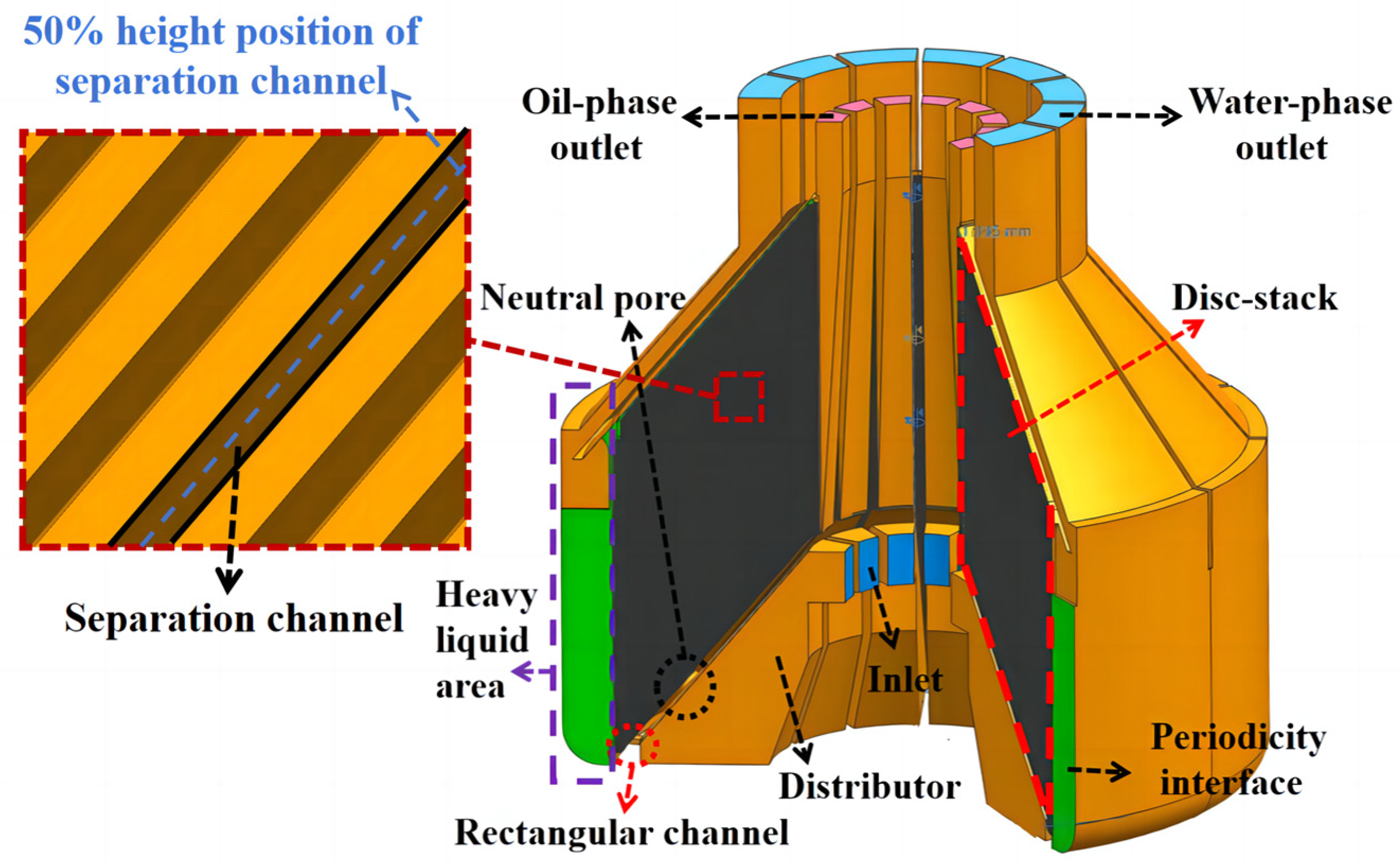
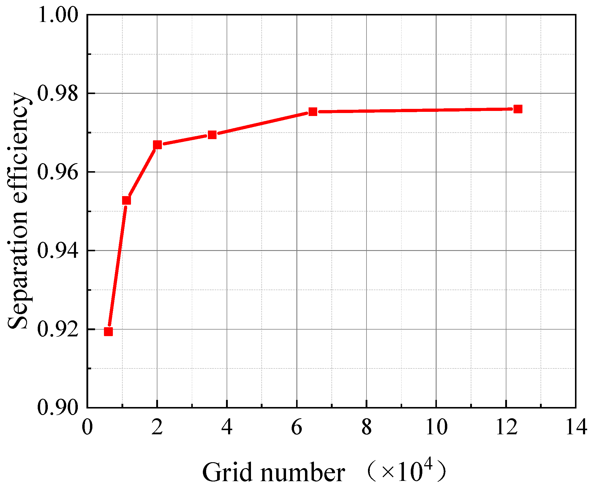
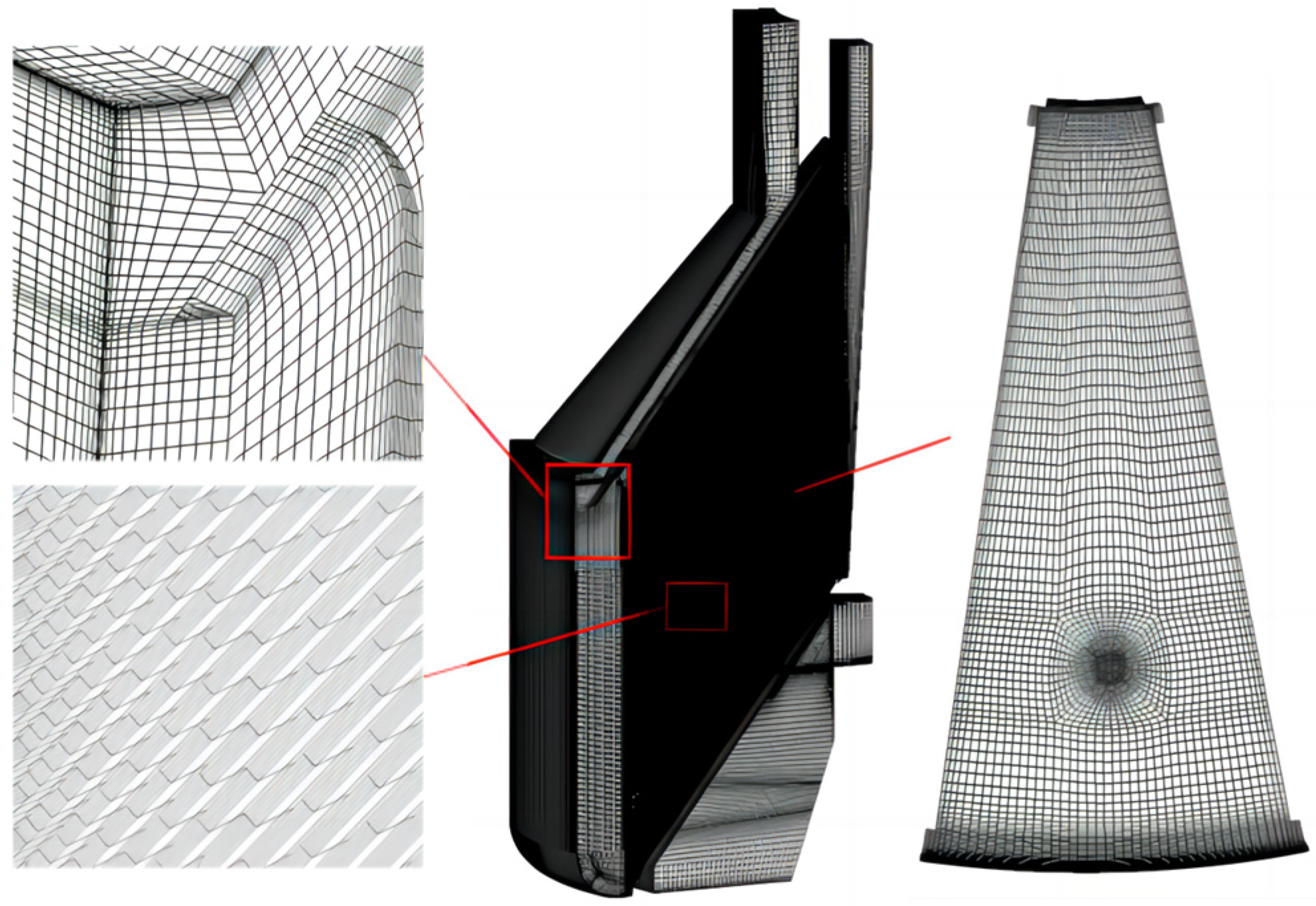
2.1. Model and Meshing

Disc stack centrifuge is a commonly used piece of equipment for separation and purification in petrochemical, biopharmaceutical, food processing, and other fields.
The subject of this paper is a marine disc stack centrifuge. The physical model of the disc stack centrifuge is shown in Figure 1. The main parameters of the disc stack centrifuge are as follows: Qd is the design flow rate, Nd is the design rotational speed, and D is the maximum radius. The maximum diameter of the disc is 0.856D, and the minimum diameter of the disc is 0.266D. The height of the disc stack centrifuge is 3.804D. It has a separation channel height of 0.018D. The diameter of the neutral pore is 0.079D. The flow medium in this paper is oil and water, and the specific parameters are shown in Table 1.
According to the solid model of the disc stack centrifuge, the fluid domain model of the bowl component of the disc stack centrifuge is established using UG NX 12.0 software, as shown in Figure 2. In this, the inlet and outlet of the fluid domain of the bowl component are extended appropriately to minimize the impact of geometrical model variations on the computational results.
Combining Figure 1 and Figure 2, the working principle of the disc stack centrifuge is as follows: the oil–water mixture enters the bowl component of the disc stack centrifuge through the inlet, passes through the distributor, a part of the liquid flows through the rectangular channel to the heavy liquid area of the bowl component, and the other part of the liquid passes through the neutral pores to the separating channel consisting of multi-layer discs. The bowl components rotate at high speed, driving the oil–water mixture to rotate. When rotating at the same speed, oil and water are subjected to different centrifugal forces due to their different densities. Under the action of centrifugal force, oil and water move in opposite directions, with oil flowing towards the oil phase outlet and water flowing towards the water phase outlet. Eventually, the separation of oil and water is completed.
Considering the geometrical model and the rotational periodicity of the internal flow process, 1/12 of the fluid domain is selected as the computational domain. Numerical simulation of the oil–water two-phase flow in a single-layer separation channel is carried out using the Mixture model to verify the grid independence. Structural meshing of the computational domain was performed using ICEM CFD 2021 R1 software. The grid scheme is shown in Table 1. Under the design condition (design rotational speed: Nd, design flow: Qd), the volume fraction of the water phase at the inlet of the computational domain is set to be 5%, and the particle size of the water phase is 10 μm. The flow process inside the separation channel directly affects the separation effect, so the separation efficiency η is used as a validation parameter, which is defined as:
η = 1 c 1 c 0
In the equation, c0 is the volume fraction of the water phase at the inlet of the computational domain, and c1 is the volume fraction of water at the outlet of the oil phase of the computational domain.
The grid independence verification results are shown in Figure 3. It can be seen that the separation efficiency of the separation channel increases with the increase in the number of grids. When the total number of grids exceeds 60,000, the separation efficiency of the separation channel is considered to be independent of the number of grids.
Due to the complex structure of the disc stack centrifuge bowl and the translational periodicity of the separation channel in the Z-axis direction, a geometric chunking, translational replication, and O/H meshing approach is used to structurally mesh the computational domain. The separation channel mesh is configured according to Scheme 5 in Table 2 and the mesh near the wall is encrypted, i.e., the height of the first layer of the mesh at the wall is less than 0.05 mm and the mesh growth rate is 1.1. There are about 18 million meshes in the computational domain. The Y PLUS < 20 in the region close to the wall meets the requirements of the RNG k-epsilon turbulence model. The RNG k-epsilon model in the model library has a wider range of applicability as well as higher reliability and accuracy compared to other models based on the consideration of fluid physics phenomena, simplification of special problems, and the requirement of simulation accuracy [2]. Therefore, in this paper, the RNG (Re-Normalization Group) k-epsilon turbulence model with wall function treatment has been chosen for the numerical simulation. The transport equations for the RNG k-epsilon turbulence model are [25]:
t ρ k + x i ρ k u i = x j α k μ e f f k x j + G k + G b ρ ε Y M + S k
and
t ρ ε + x i ρ ε u i = x j α ε μ e f f ε x j + G 1 ε ε k G k + C 3 ε G b C 2 ε ρ ε 2 k R ε + S ε
In these equations, k is the turbulence kinetic energy; ε is the turbulence dissipation rate; Gk represents the generation of turbulence kinetic energy due to the mean velocity gradients; Gb is the generation of turbulence kinetic energy due to buoyancy; YM represents the contribution of the fluctuating dilatation in compressible turbulence to the overall dissipation rate; and C1ε, C2ε, and C3ε are constants. The quantities αk and ae are the inverse effective Prandtl numbers for k and ε, respectively, and Sk and are user-defined source terms.
Figure 4 shows the overall mesh layout and local area mesh details of the computational domain. Using this meshing method, the computational requirements are met while capturing the flow details in the separation channel.

2.2. Numerical Methods and Boundary Conditions

In this paper, numerical simulation bowl components of the disc stack centrifuge are carried out based on ANSYS Fluent 2021 R1 software. The Mixture-PBM coupled model was used, the turbulence model was used for the coalescence model [26], and the Luo model was used for the breakup model [27]. The population balance equation is solved by the discrete method. The coupled method is chosen as the solution method, and the first-order windward format is chosen as the difference format. In addition, the RNG k-epsilon model is chosen as the turbulence model. The energy equation is used to describe the transfer and conversion of energy in the fluid, the wall is set as an adiabatic wall, and viscous heating is considered. The velocity inlet was chosen as the boundary condition for the inlet of the computational domain, and the static temperature of the inlet was 288.15 K; the volume content of the aqueous phase of the inlet was 5%. The direction of velocity at the inlet in the rotating coordinate system is perpendicular to the inlet boundary, and the two phases of oil and water at the inlet have the same velocity. Turbulence intensity and hydraulic diameter were chosen to describe the inlet turbulence, with a turbulence intensity of 5% and a hydraulic diameter of 22 mm. The surface tension coefficient was 0.018 N/m. The rest were the default values provided by ANSYS Fluent 2021 R1.
The particle diameter of the water droplets at the inlet of the disc stack centrifuges was measured by the ML-1 oil–liquid abrasive particle detector, and the results showed that the oil–water mixture contained eight different diameters of water droplets ranging from 5 µm to 200 µm. The experimental measurements were fitted to a normal distribution function, as shown in Figure 5.
When the boundary condition for the outlet of the computational domain is a free exit boundary or a flow outlet boundary, this leads to a negative pressure field in the final result that does not match the actual situation. In reality, the liquid at the outlet of the computational domain under the action of centrifugal force will form a free liquid surface with the air, and this free liquid surface is parallel to the axis of rotation [28]. Therefore, the boundary conditions at the exit of the computational domain should be a pressure distribution that increases with the radius, and this pressure distribution conforms to the laws of the centrifugal hydraulic pressure equation, as shown in Equation (4).
P r = ρ ω 2 r f r r d r
In the equation, ρ is the density of the liquid, and the unit is m3/kg; ω is the rotational angular velocity, and the unit is rad/s; r is the radius at any position, and the unit is m; and rf is the radius of the free liquid surface at the outlet of the oil phase or water phase, and the unit is m.
To simplify the calculations, in this paper, the fluid domain of the air portion at the outlet of the oil phases and water phases is deleted, and the free liquid surface is treated as a wall boundary. Due to the low water content of the fluid in the computational domain, the radius of the free liquid surface at the outlet of the aqueous phase is considered to be the same as the radius of the inlet of the aqueous phase centripetal pump, which is taken to be rf,h = 0.398D. The radius of the free liquid surface at the outlet of the oil phase is related to the downstream flow state and the specific working condition; here, rf,l = 0.217D is selected.
The wall boundary conditions are set in the real physical state. The solid wall surface corotating with the bowl is set as the rotating wall surface. Considering that the processing of the disc contains polishing and other processes [29], the roughness height is set to 0.5 and the roughness constant to 0.5. The wall adhesion angle of water in the oil environment is set to 90°. As a result of slicing the fluid domain, two planes are created on the computational domain, setting the boundary conditions on this plane as periodic boundary conditions.

3. Results and Discussion

The rotational speed coefficient Nh of the disc stack centrifuge is defined as follows:
N h = N N d
In the equation, Nh is a dimensionless parameter; N is the actual rotational speed of the disc stack centrifuge, the unit is rpm; and Nd is the design rotational speed of the disc stack centrifuge, the unit is rpm.
The flow coefficient Qh of the disc stack centrifuge is defined as follows:
Q h = Q Q d
In the equation, Qh is a dimensionless parameter; Q is the actual flow of the disc stack centrifuge, the unit is m3/h; and Qd is the design flow of the disc stack centrifuge, the unit is m3/h.

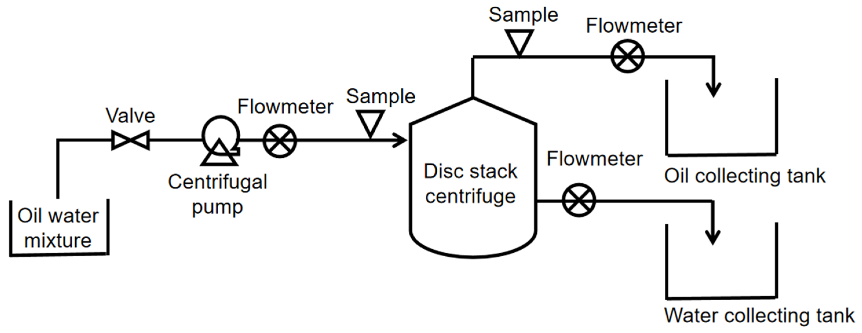
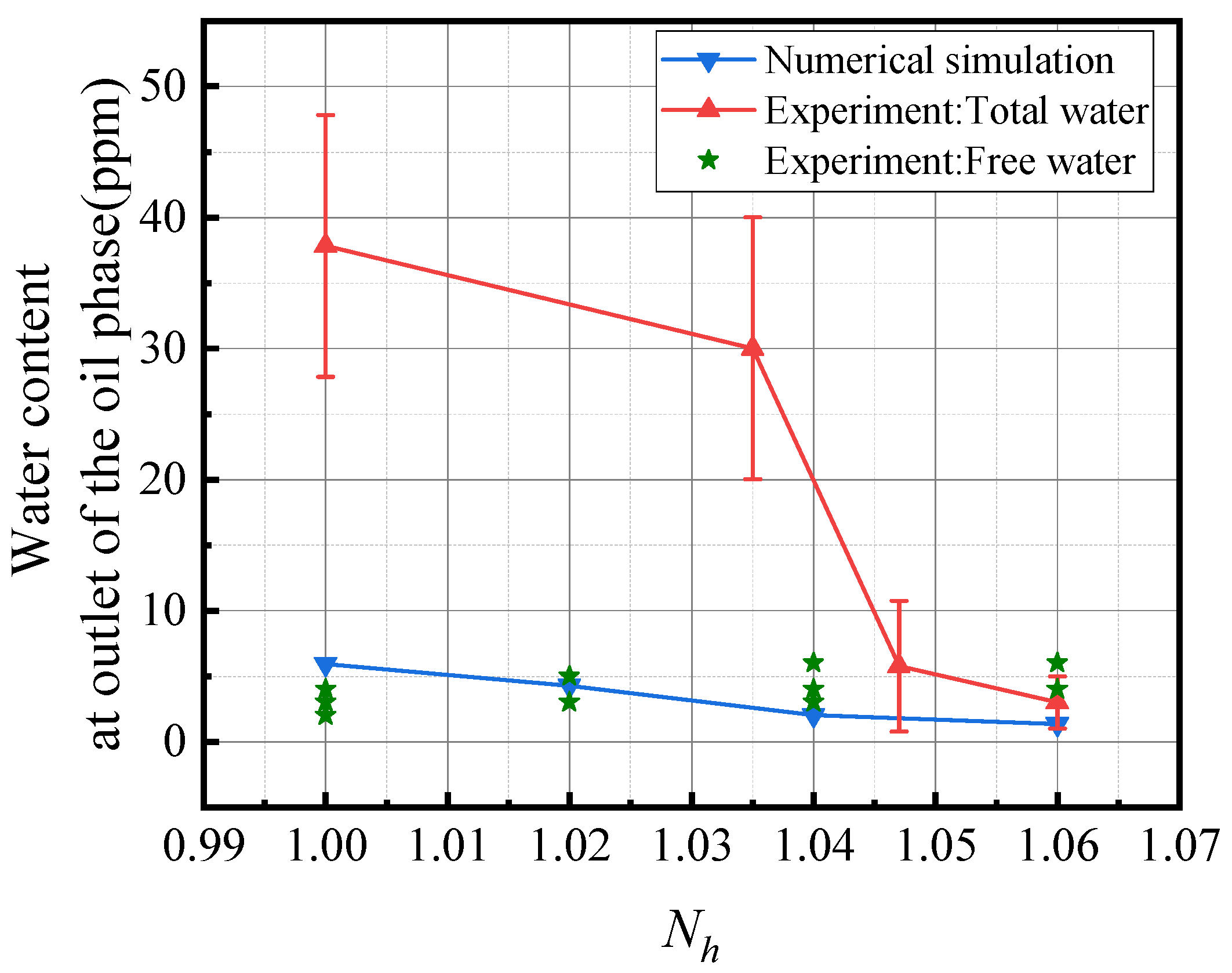
3.1. Comparison of Experimental and Numerical Simulation Results

The operating conditions of the test were as follows: a full-size disc stack centrifuge prototype was used, with an inlet water content of 5% and an inlet water droplet particle diameter of 5–200 microns under design flow conditions. The particle diameter and content of water droplets at the inlet and outlet of the disc stack centrifuge were measured using the ML-1 oil–liquid abrasive particle detector. The experimental flow chart is shown in Figure 6. The measurement error when measuring free water with the ML-1 oil-liquid abrasive particle detector is 1 ppm, 1 ppm = 10−6.
Calculated from Equation (1), the separation efficiencies of both experimental and numerical simulation results are above 99%; the units of the vertical coordinates in Figure 7 are in ppm to clearly show the differences in the separation efficiencies under different operating conditions.
The main forms of water existence in oil are dissolved water, emulsified water, free water, and so on. Figure 7 shows the effect of different rotational speeds on the separation efficiency of a disc stack centrifuge at a flow rate of Qd. The experimental data include data on total water content and free water content, and the numerical simulation data are for free water content. The vertical axis indicates the water content at the outlet of the oil phase, and the horizontal coordinate indicates the rotational speed of the disc stack centrifuge. The results show that at the rotational speed coefficients Nh = 1.0~1.06, the total water content at the outlet of the oil phase decreases gradually with the increase in rotational speed, and the separation efficiency of the disc stack centrifuge increases gradually. This is because when the speed of rotation is greater, water droplets with smaller particle sizes can converge into water droplets with larger particle sizes, which can then be separated. With the increase in rotational speed, the free water content at the oil phase outlet always stays within the range of 3–6 ppm, which is basically in perfect agreement with the numerical simulation results.

3.2. Effect of Ribs on the Distribution of Flow Field Parameters

Cross-sections made at positions 1-1, 2-2, and 3-3 are shown in Figure 8, where ribs are at positions PS and SS, with PS representing the pressure surface and SS representing the suction surface. u represents the rotational velocity of the liquid in m/s; c represents the absolute velocity of the liquid, i.e., the velocity in the stationary coordinate system, in m/s; and w represents the relative velocity of the liquid, i.e., the velocity in the rotational coordinate system, in m/s.
To verify the reliability of the numerical simulation, the separation channel of the middle layer is selected, and the pressure distribution at the cross-section position of the separation channel 2-2 is compared. The numerical simulation results and theoretical calculations at the 50% height position of the separation channel are shown in Figure 9.
The curve is approximately parabolic; as the radius increases, the pressure also increases, and the pressure gradient gets bigger and bigger, which satisfies the pressure distribution law of the centrifugal hydraulic pressure formula (Equation (4)). The absolute pressure at the smallest radius is 0.53 MPa, and the absolute pressure at the largest radius is 5.65 MPa.
From Equation (4), it can be seen that the circumferential velocity of the fluid has a great influence on the pressure field. Due to the presence of ribs in the disc (PS and SS in Figure 8), the flow hysteresis is reduced. So, the difference between the theoretical results and the numerical simulation results is not big, and the numerical simulation results can reach 98% of the theoretical results. The numerical simulation results of Cui et al. [30] are only 73% of the theoretical results due to neglecting the role of ribs.
The circumferential velocity is a measure of the speed of rotation, and the theoretical circumferential velocity can be calculated by the formula. The definition of the formula for circumferential velocity is as follows:
V c = ω r
In the equation, ω is the rotational angular velocity, the unit is rad/s; and r is the radius at any position, the unit is m.
Selecting the separation channel of the middle layer and comparing the circumferential velocities at the cross-section position of separation channel 2-2, the numerical simulation results and theoretical calculations at the 50% height position of the separation channel are shown in Figure 10. The curve is linearly distributed; with the radius increasing, the circumferential velocity increases, the circumferential velocity gradient is unchanged, and the numerical simulation results are consistent with the distribution law of the theoretical results.

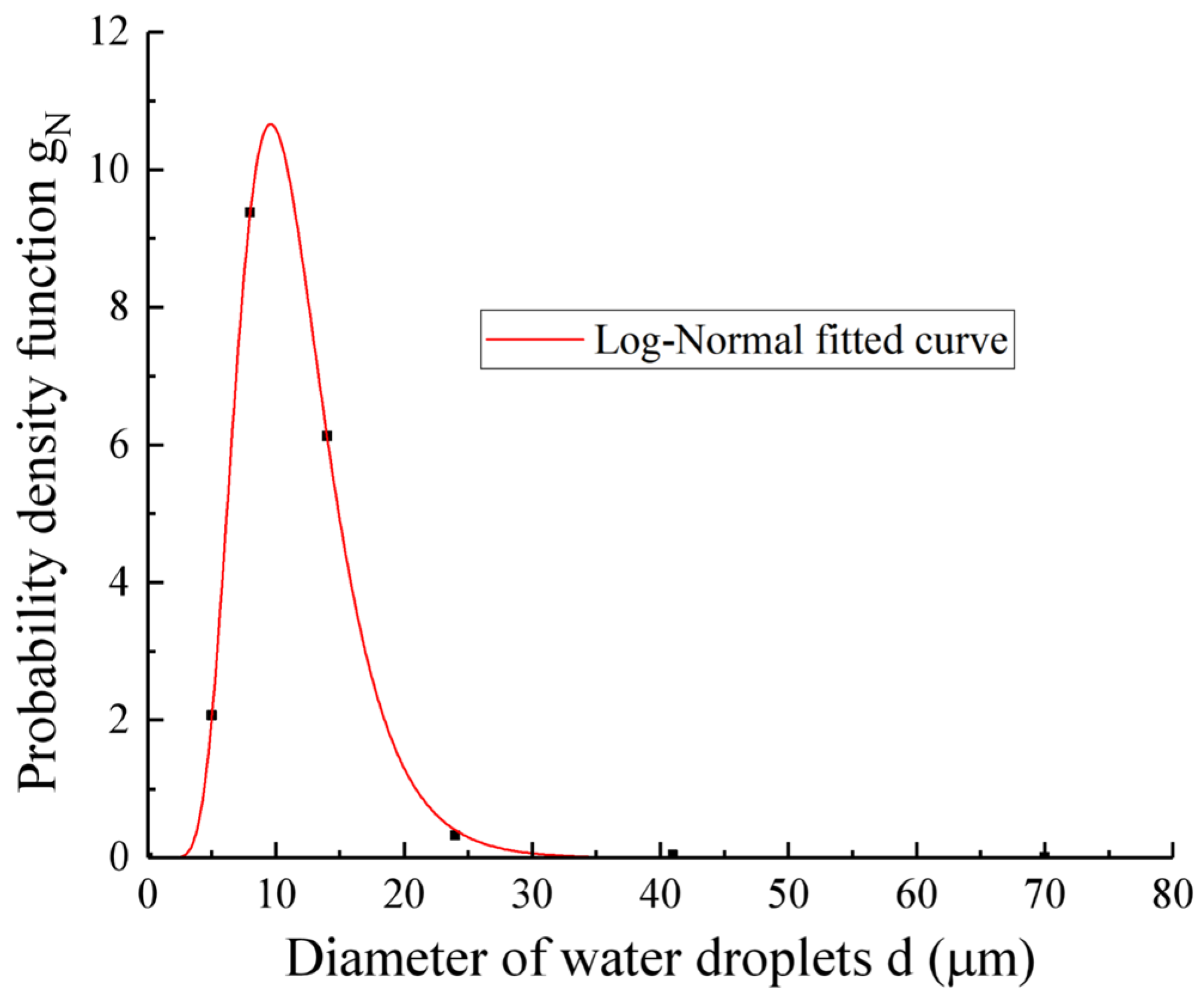
3.3. Coalescence and Breakup of Water Droplets

For liquid–liquid separation of the disc stack centrifuge, the internal two-phase flow process, the dispersed phase droplets will occur in the coalescence and breakup phenomena. Figure 11 shows that at the inlet of the rising channel (a vertical channel consisting of neutral pores), the small-sized water droplets become fewer, and the large-sized water droplets increase in number compared to the inlet of the bowl component.
After the oil–water mixture enters the distributor, water droplets with smaller particle sizes coalesce into water droplets with larger particle sizes because most of the water has settled to the lower surface of the disc stack shelf inside the distributor, and the distance between the water droplets decreases. When the distance between droplets is less than 10 nm, the droplets instantly undergo coalescence due to intermolecular force [31].
Figure 12 shows the particle size distribution of water droplets at different cross-sectional locations. The particle size of the water droplets remains at a maximum in the bowl component heavy liquid region of the disc stack centrifuge. The heavy liquid zone should be in an oil-in-water (O/W) state, but since only the pre-set particle diameters of the dispersed phase can be modelled, it can be assumed that the water droplets in the heavy liquid zone, which maintain the largest particle diameters, are converted from the dispersed phase to the continuous phase.
As can be seen from Figure 12b, the water droplets begin to coalescence already inside the distributor, sliding along the lower surface of the disc stack shelf and passing through the rising channel into each separation channel, where the coalescence process dominates, but outside the small end of the discs, the breakup process occurs, and the particle size of the droplets decreases.

3.4. Three-Dimensional Flow Characteristics of the Internal Flow Field

Figure 13 shows the surface streamline diagram at 50% height inside the separation channel. Combined with the velocity triangle in Figure 8, the relative velocity of the liquid can be obtained, with the colors of the streamlines representing the values of the relative velocity of the liquid. It can be seen that after the oil–water mixture enters the separation channel from the neutral pore, there is an inertial effect in the rotating coordinate system with a rotational speed of Nd, and it flows first to the ribs at the position of the pressure surface and then towards the small end of the disc. During flow to the small end of the disc, there is a tendency to flow towards the ribs at the suction surface due to the effect of the Coriolis force, and the liquid flowing to the large end of the disc tends to deflect towards the ribs at the pressure surface.
The vortex phenomenon occurs near the neutral pore due to the interaction of the water and oil phases; it gradually increases with the number of layers in the separation channel, and the vortex structure becomes simpler. However, at the large end of the disc, near the ribs of the pressure surface, a relative stagnation zone with low flow velocities occurs. The stagnation zone is larger in the separation channel of the middle layer.
The viscous fluid motion in the separation channel has two velocity components: the radial velocity along the direction of the generatrix and the relative circumferential velocity due to the Coriolis force. Based on these two features, Golikin [28] obtained a dimensionless number λ by solving the Navier–Stokes equations, which is used to describe the flow law of the liquid in the separation channel.
λ = h ω s i n α ν
In the equation, h is the height of the separation channel, and the unit is m; ω is the disc stack centrifuge rotation speed, and the unit is rad/s; α is the angle between the generatrix of the disc and the rotation axis, and the unit is °; and ν is the kinematic viscosity of the liquid, and the unit is m2/s.
Under the influence of various velocity components, the trajectory of the liquid flowing from the neutral pore into the separation channel is not parallel to the generatrix of the disc. Figure 14 shows the streamline diagram near the neutral pore at different λ values. It can be seen that as the λ value increases, the deviation between the liquid motion trajectory and the direction of the busbar increases.
Figure 15 shows the circumferential velocity distribution in the separation channels of layers 1–6 within the range of −1° to 1° in the circumferential direction. It can be seen that the values of the circumferential velocity are different in the circumferential direction, which is due to the presence of vortex flow in the separation channel, and the circumferential velocity at the middle of the separation channel is higher than the circumferential velocity at the near-wall surface.
Figure 16 shows the radial velocity distribution in the separation channels of layers 1–6 within the range of −1° to 1° in the circumferential direction. It can be seen that the radial velocity in the middle of the separation channel is higher than the radial velocity near the wall.
Figure 17 shows a cloud plot of the turbulent kinetic energy at 50% height in the different separation channels. The turbulent kinetic energy is less than 0.04 m2/s2 in most areas of the separation channel. Turbulence occurs mainly near the neutral pore and at the large and small end positions of the disc. As can be seen from Figure 13, the fluid in the neutral pore position when the flow is vortex-like, flow separation is large. The fluid in the disc has large-end and small-end positions, and the fluid is about to flow from the inside of the disc to the outside of the disc, where it is very easy to find the flow instability phenomenon.
The turbulent kinetic energy at the position of the pressure surface (PS) is larger than that at the position of the suction surface (SS) because the oil–water mixture flows through the neutral pore into the separation channel and then flows to the pressure surface. The process creates a rapid change in the direction of the velocity, leading to the enhancement of the velocity pulsation between the neutral pore and the pressure surface. In addition, as the number of layers increases, the turbulence kinetic energy at the vicinity of the neutral pore decreases, indicating that the fluid becomes more stable as it flows backward.
Figure 18 shows the change in throughput for each layer of the separation channel from bottom to top for three different oil-phase outlet radii (rf,l). It can be seen that the processing capacity of the separation channel at the bottom is smaller, and the processing capacity of the separation channel from the 40th layer to the 160th layer is maintained at Qh = 0.0033~0.0042, with small fluctuations, which is favorable to the centrifugal settling process. The processing capacity of the top separation channel gradually increases, but the water content in the liquid entering the top separation channel is small. Therefore, the increase in the treatment capacity of the top separation channel has a limited effect on the separation effect.
Figure 19 shows the change in water content in the liquid entering the separation channel from the neutral pore. It can be seen that the water content in the liquid in the neutral pore gradually decreases, and the water content of the liquid in the first layer of the separation channel is less than 1%. This is because after the oil–water mixture enters the distributor, a large amount of water settles on the upper surface of the distributor (i.e., the lower surface of the disc-stack shelf) and flows through the rectangular channel to the bowl’s heavy liquid area. Fluctuations in the water content in the bottom separation channel are caused by flow instability. Flow instability can cause water that settles in the distributor to pass through the neutral pore into the separation channel.
Figure 20 shows the water content at the 2–2 cross-section location of the bowl component. When rf,l = 0.217D, the location of the interface between the oil and water is beyond the large end of the disc, and the volume fraction of water at the outlet of the oil phase is 6 ppm.
Figure 21 shows the variation in the water content at the small end of the separation channel for each layer, that is, the variation in the separation efficiency of the separation channel for each layer. The separation efficiency of most of the separation channels is less than that of the disc stack centrifuge, and it deteriorates in the bottom, middle, and top separation channels.

4. Conclusions

In this paper, based on the Mixture-PBM coupling model, a numerical simulation study was carried out on a real-size disc stack centrifuge, and the results of the study showed that:
  • The error between the numerical simulation results and the separation efficiency of the test results is less than 1%. When Nd = 1~1.06, the separation efficiency of the disc stack centrifuge increases with the increase in rotational speed. When Nd = 1.06, the separation efficiency η = 99.99%.
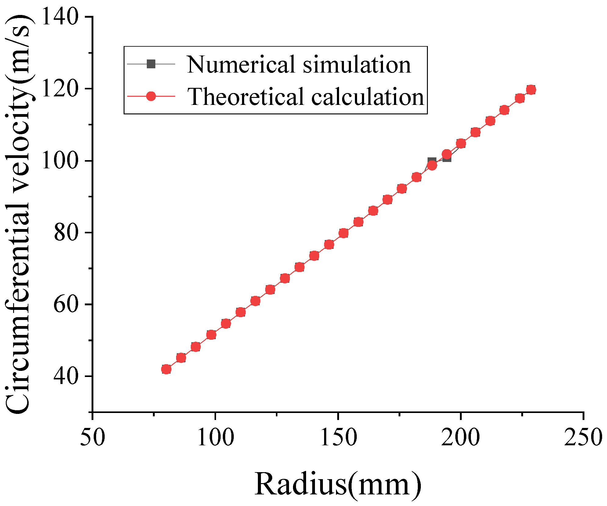
  • Considering the ribs of the disc, the hysteresis phenomenon of the liquid flow in the disc stack centrifuge is significantly reduced, and the results of numerical simulation (parameter distribution of the flow field) can reach 98% of the theoretical results, which verifies the reliability of the numerical simulation results. The ribs of the disc have an indispensable role.
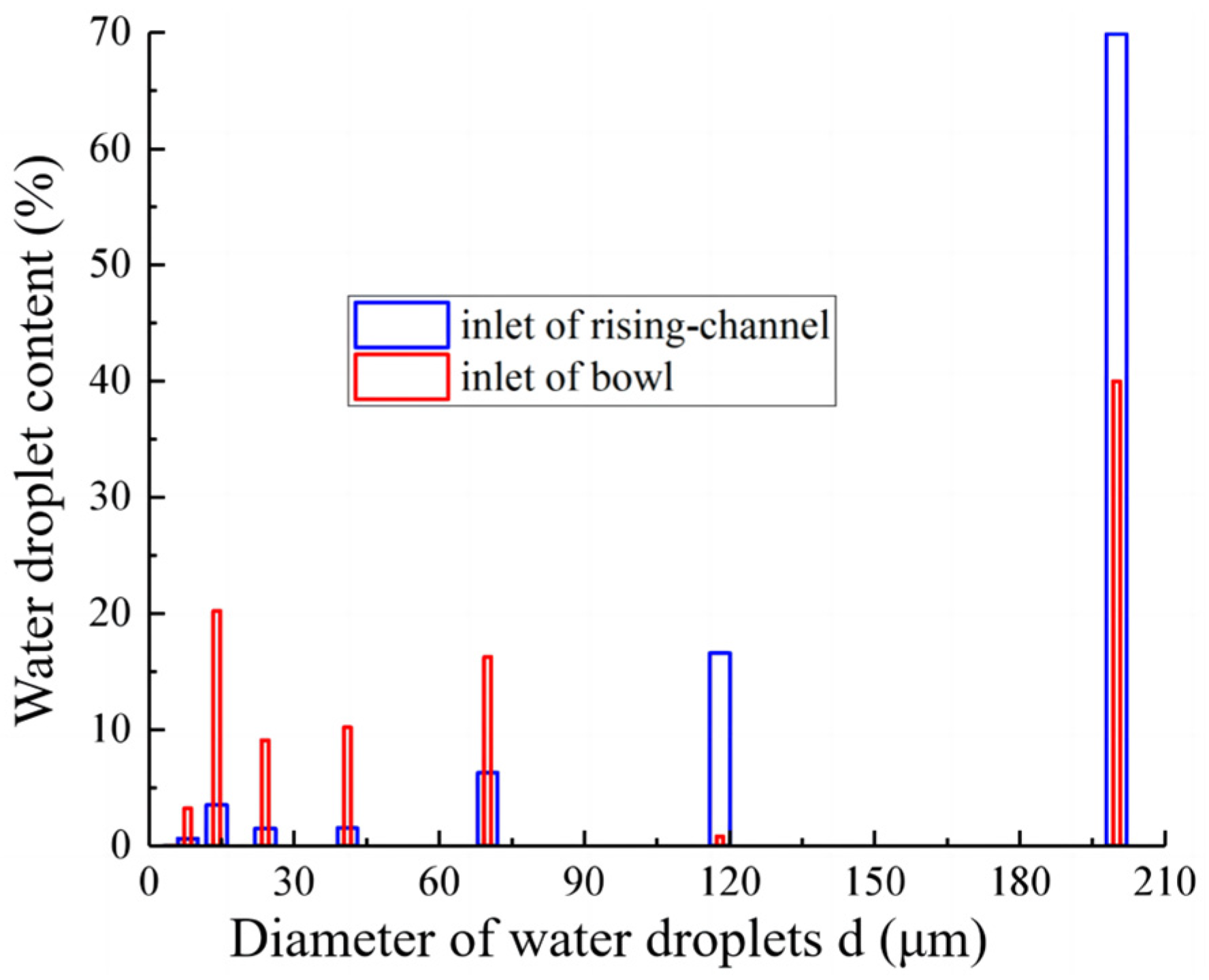
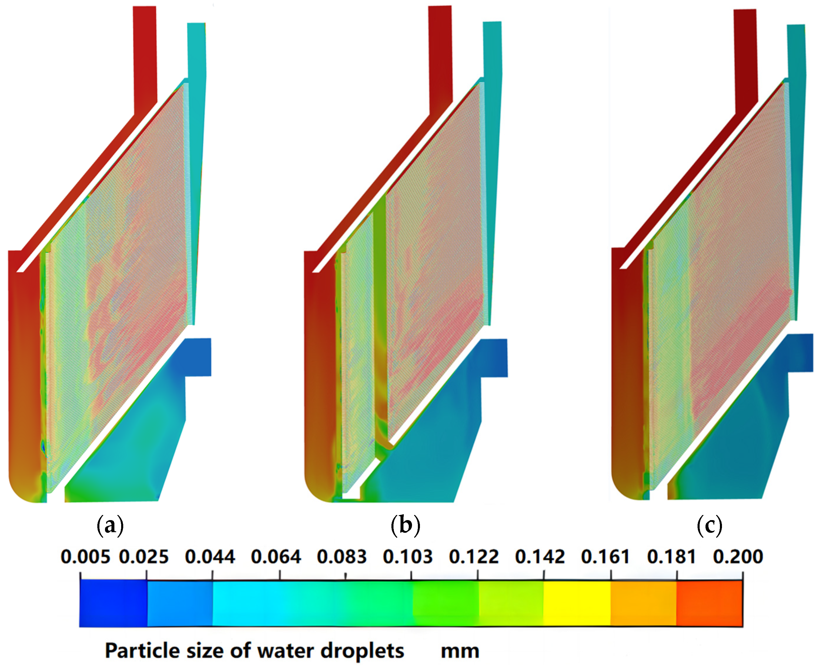
  • A total of 90% of the water droplets in the oil–water mixture complete coalescence and precipitation in the distributor and do not pass through the rising channel but enter the heavy liquid area of the bowl through the rectangular channel and are discharged to the disc stack centrifuge through the water-phase outlet. The coalescence phenomenon of the water droplets entering the separation channel is greater than the breakup phenomenon.
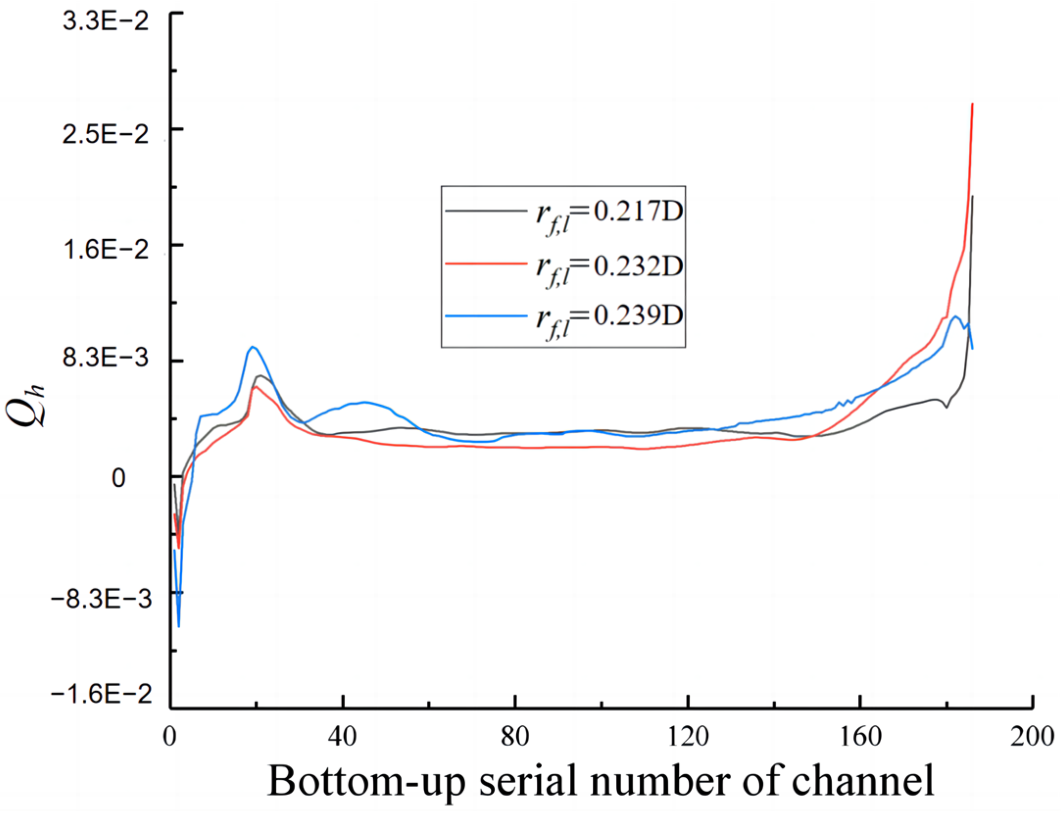
  • The water content in the rising channel gradually decreases, and 95% of the water enters the bottom separation channel of the bowl component. The processing capacity of each layer of the separation channel gradually increases, showing the law of having a small bottom layer, large top layer, and uniform middle layer.
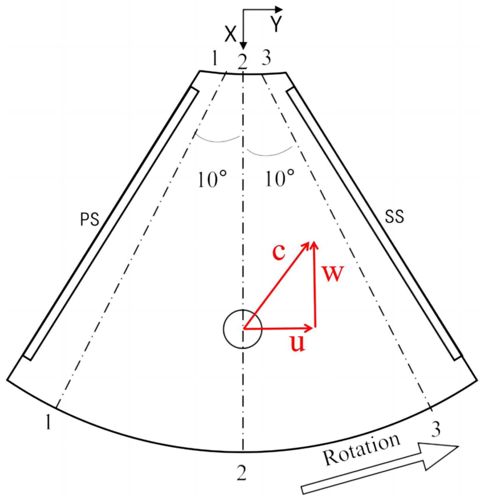
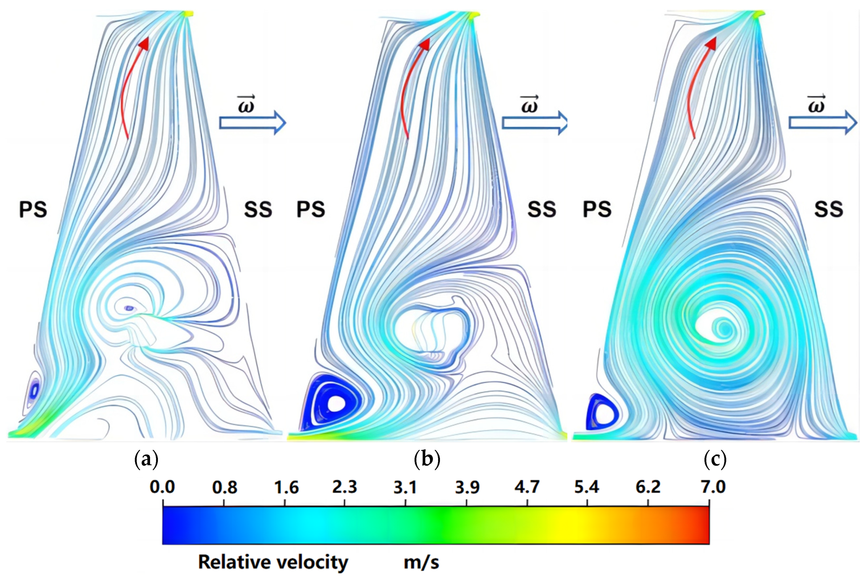
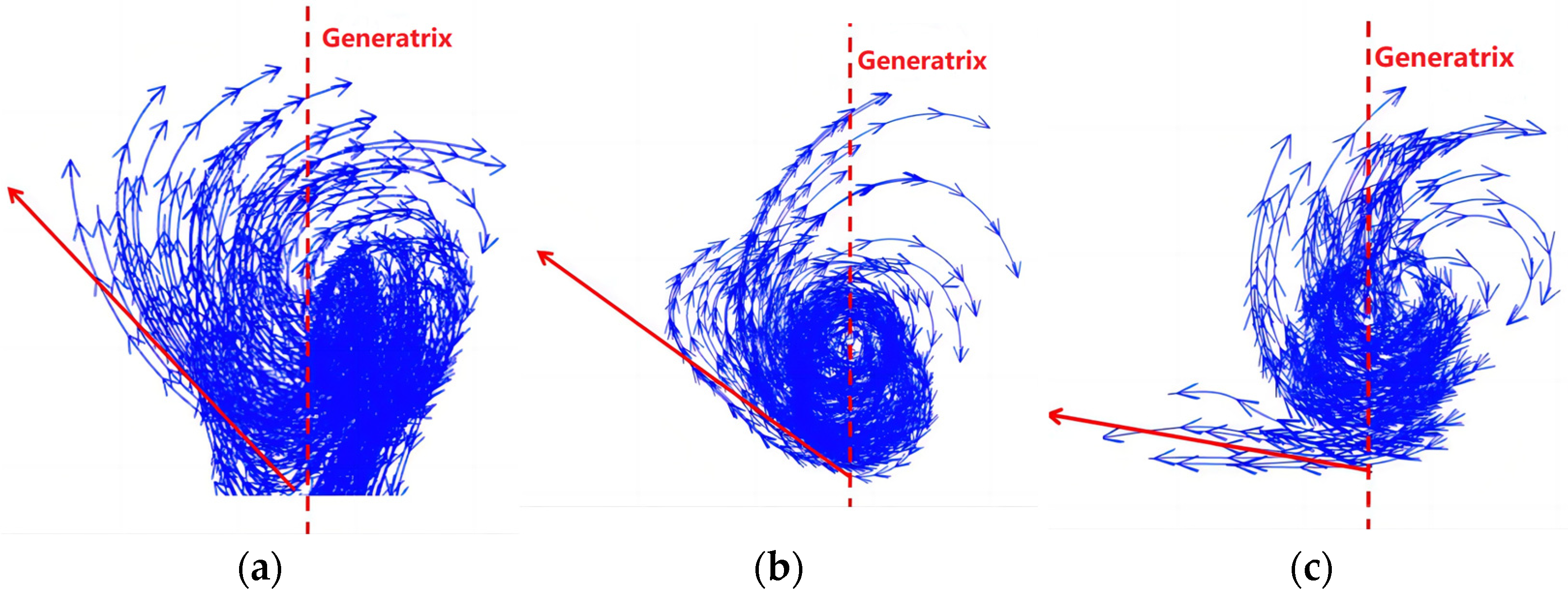
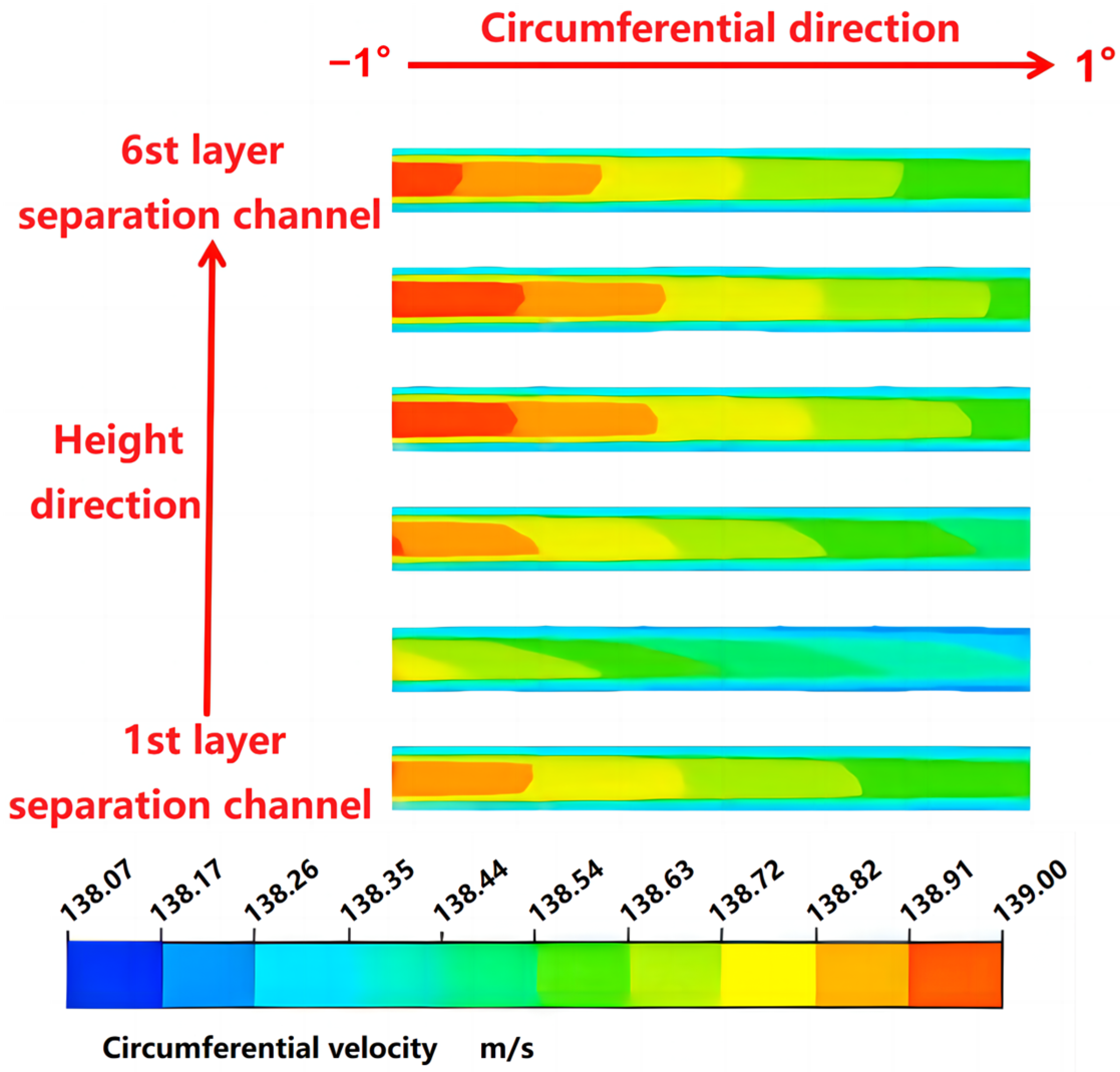
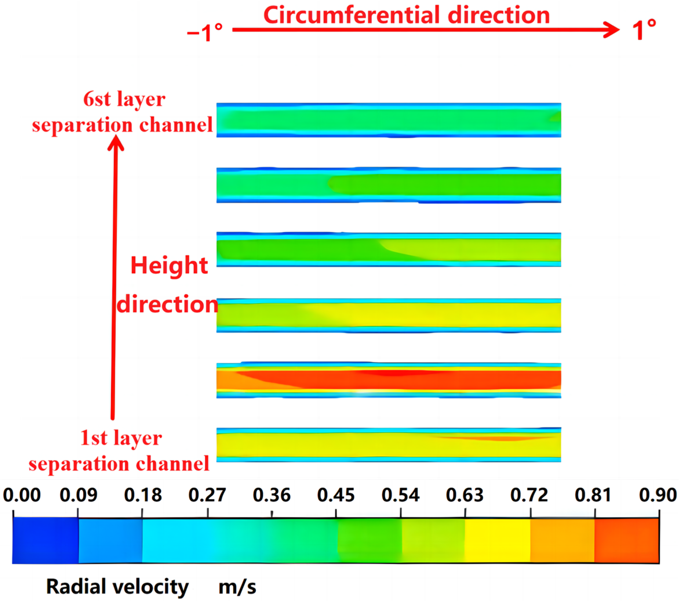
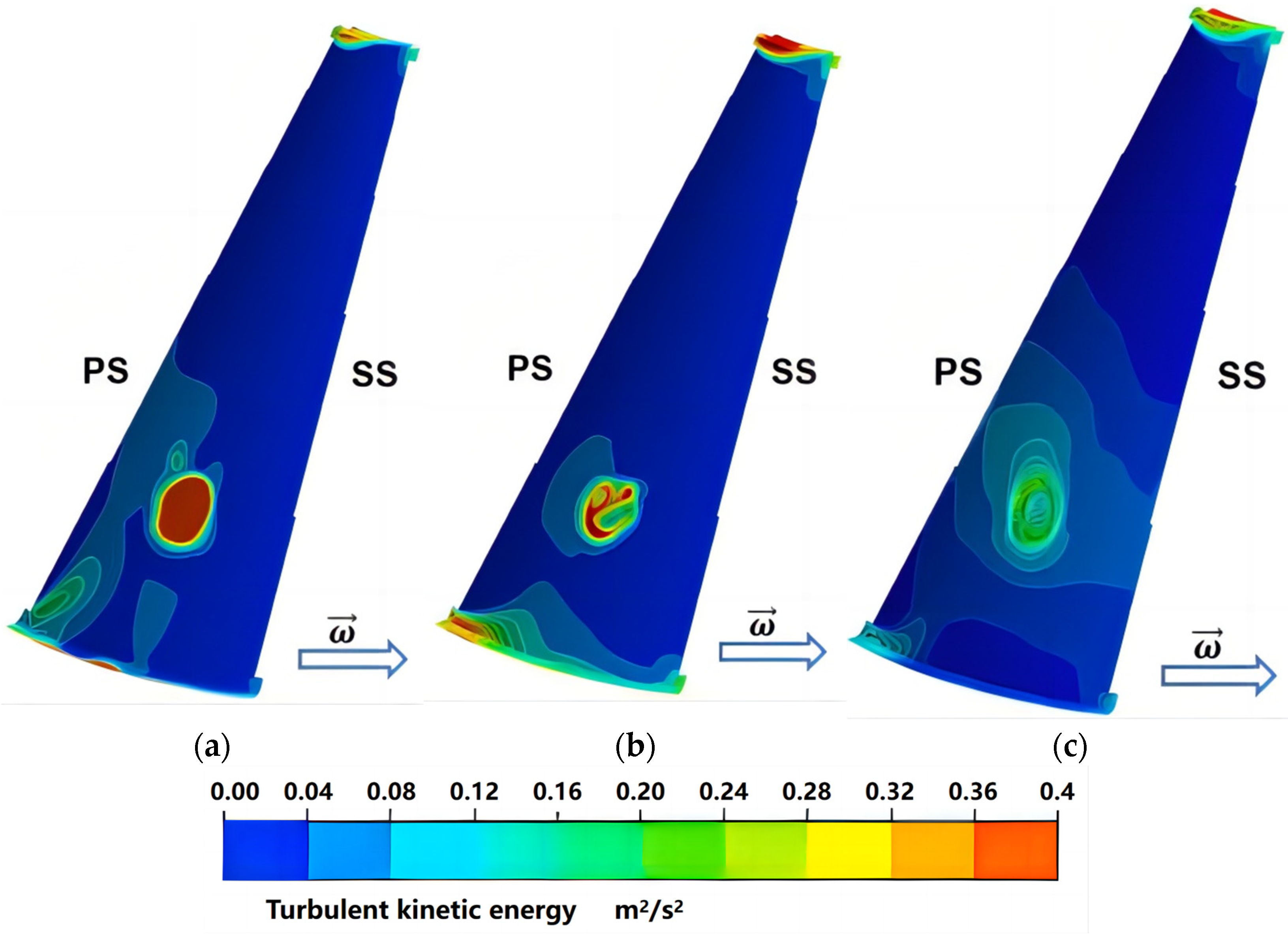
  • After the oil–water mixture enters the separation channel from the neutral pore, under the action of Coriolis force, the motion trajectory is not parallel to the generatrix of the disc but forms a vortex near the neutral pore, and the area of the vortex is small at the bottom and large at the top. The coalescence phenomenon and the water content of the water droplets affect the vortex scale, which is different from the classical two-dimensional simplified model with obvious three-dimensional characteristics. With the increase in λ, the motion trajectory of the liquid is more and more deviating from the generatrix direction of the disc. In addition, the circumferential and radial velocities in the separation channel show a law of being large in the middle and small near the wall.

Author Contributions

Writing—original draft preparation, H.D. and S.L. (Shoulie Liu); Methodology, S.L. (Shoulie Liu), L.C. and S.L. (Shamiao Luo); Validation, C.H. and X.S.; Writing—review and editing, S.L. (Shaobin Li); Visualization, R.W.; Funding acquisition, S.L. (Shaobin Li). All authors have read and agreed to the published version of the manuscript.

Funding

This research received no external funding.

Institutional Review Board Statement

Not applicable.

Informed Consent Statement

Not applicable.

Data Availability Statement

The original contributions presented in the study are included in the article, further inquiries can be directed to the corresponding author.

Conflicts of Interest

Authors Hefeng Dong, Ran Wan and Changan Huang were employed by the company China State Shipbuilding Corporation Limited. The remaining authors declare that the research was conducted in the absence of any commercial or financial relationships that could be construed as a potential conflict of interest.

Nomenclature

ηSeparation efficiency of disc stack centrifuge
c0Volume fraction of the water phase at the inlet of the computational domain
c1Volume fraction of the water phase at the outlet of the oil phase of the computational domain
QdDesign flow of the disc stack centrifuge (m3/h)
QActual flow of the disc stack centrifuge (m3/h)
QdDesign flow of the disc stack centrifuge (m3/h)
NhRotational speed coefficient of the disc stack centrifuge
NActual rotational speed of the disc stack centrifuge (rpm)
NdDesign rotational speed of the disc stack centrifuge (rpm)
DMaximum radius of the disc stack centrifuge (m)
PCentrifugal hydraulic pressure difference at the free liquid surface and the inlet of the flow channel (Pa)
VcCircumferential velocity (m/s)
ρ Density of the liquid (kg/m3)
ω Rotational angular speed of the liquid (rad/s)
rRadius at any position in the computational domain (m)
rfRadius of the free liquid surface at the outlet of the oil phase or water phase (m)
rf,lRadius of the free liquid surface at the outlet of the oil phase (m)
rf,hRadius of the free liquid surface at the outlet of the water phase (m)
PSRepresents the pressure surface
SSRepresents the suction surface
λDimensionless number that describes the regularity of the flow of a liquid in a separation channel
hHeight of the separation channel (m)
αAngle between the generatrix of the disc and the rotation axis (°)
νKinematic viscosity of the liquid (m2/s2)
CFDComputational Fluid Dynamics
PBMPopulation Balance Model
VOFVolume of Fluid
SIMPLESemi-Implicit Method for Pressure-Linked Equations
RNGRe-Normalization Group
uRotational velocity of the liquid (m/s)
cAbsolute velocity of the liquid (m/s)
wRelative velocity of the liquid (m/s)
kTurbulence kinetic energy
εTurbulence dissipation rate
GkGeneration of turbulence kinetic energy due to the mean velocity gradients
GbGeneration of turbulence kinetic energy due to buoyancy
YMContribution of the fluctuating dilatation in compressible turbulence to the overall dissipation rate

References

  1. Costagli, G. The use of disc stack centrifuge in the virgin olive oil industry. J. Agric. Eng. 2018, 49, 75. [Google Scholar] [CrossRef]
  2. Liu, S.; Dong, H.; Li, S.; Song, X. Study on the Influence of Working Characteristics of Centripetal Pump Based on VOF/Mixture Model. Processes 2024, 12, 1376. [Google Scholar] [CrossRef]
  3. Yuan, H. Separation Engineering; China Petrochemical Press: Beijing, China, 2002; pp. 113–115. [Google Scholar]
  4. Kombélé, A.; Steve, C.; Emmanuel, J.; Joseph, K. White-flesh guava juice clarification by a fixed-angle conical rotor centrifuge laboratory and characterization of continuous disk stack centrifuges. Heliyon 2022, 8, e11606. [Google Scholar] [CrossRef]
  5. Abu-Shamleh, A.; Najjar, Y. Optimization of mechanical harvesting of microalgae by centrifugation for biofuels production. Biomass Bioenergy 2020, 143, 105877. [Google Scholar] [CrossRef]
  6. Häggmark, C.; Königsson, S. Rheological Characterization of Solids Phase in Biomass Processes of Disc-Stack Centrifuges. Chem. Eng. Technol. 2018, 41, 2289–2297. [Google Scholar] [CrossRef]
  7. Fu, S.; Deng, G.; Dong, H.; Mou, Y.; Hu, Y.; Zhou, F.; Yuan, H. Numerical simulation of oil dewatering in a disc centrifuge based on PBM model. Exp. Comput. Multiph. Flow. 2023, 5, 212–220. [Google Scholar] [CrossRef]
  8. Shekhawat, L.; Sarkar, J.; Gupta, R.; Hadpe, S.; Rathore, A. Application of CFD in Bioprocessing: Separation of mammalian cells using disc stack centrifuge during production of biotherapeutics. J. Biotechnol. 2018, 267, 1–11. [Google Scholar] [CrossRef]
  9. Parvaneh, E.; Monireh, H. Optimization of industrial-scale centrifugal separation of biological products: Comparing the performance of tubular and disc stack centrifuges. Biochem. Eng. J. 2022, 178, 108281. [Google Scholar] [CrossRef]
  10. Xue, X.; Ni, Z.; Mu, F.; Liu, H.; Zhang, Q.; Lu, W.; He, J. ANSYS Stress Analysis and Measuring Verification on Disc Separator’s High Speed Bowl. Light Ind. Mach. 2021, 39, 37–42. [Google Scholar]
  11. Xu, P.; Zhao, L.; Wu, J.; Ding, Y.; Tian, Y.; Zhan, Y.; Hou, T. Study on influence of rotor systems structural parameters on dynamic characteristics of the disc separator. Mach. Des. Manuf. Eng. 2023, 52, 99–102. [Google Scholar]
  12. He, S.; Wang, D.; Yang, J.; Cai, B.; Zhao, G. Influence of Structural Parameters on Critical Speed of Vertical Shaft System of a Dish Centrifuge. Trans. Chin. Soc. Agric. Mach. 2005, 7, 57–60. [Google Scholar]
  13. Zhang, Q.; He, X. Field Dynamic Balance Test System Based on LabVIEW for Disc Separator. Mech. Eng. Autom. 2015, 3, 165–167. [Google Scholar] [CrossRef]
  14. Yuan, J.; Xie, C.; Zhu, D. Design and Analysis of Health Management Based on Logical Control of Disc Centrifugal Separator. Mech. Electr. Equip. 2020, 37, 43–48. [Google Scholar]
  15. Yang, M.; Liu, X.; Howell, J.; Cheng, H. Analysis and estimation/prediction of the disk stack centrifuge separation performance—Scaling from benchtop fixed rotor type to disk stack centrifuges. Sep. Sci. Technol. 2020, 55, 2615–2621. [Google Scholar] [CrossRef]
  16. Zheng, M. The symmetries and invariant solutions for laminar boundary layer of disc centrifuge. Chin. J. Comput. Mech. 2022, 39, 450–454. [Google Scholar]
  17. Cambiella, A.; Benito, J.; Pazos, C.; Coca, J. Centrifugal separation efficiency in the treatment of waste emulsified oils. Chem. Eng. Res. Des. 2006, 84, 69–76. [Google Scholar] [CrossRef]
  18. Janoske, U.; Piesche, M. Hydrodynamic investigations on the separation behavior of suspensions in a gap of a disk stack centrifuge with caulks. Chem. Eng. Technol. 2000, 23, 850–853. [Google Scholar] [CrossRef]
  19. Xue, X.; Shi, K. Numerical Analysis on Flow-field Characteristics of High-Speed Bowl of Latex Disc-separator. Fluid Mach. 2016, 44, 22–27. [Google Scholar]
  20. Zhang, Y.; Wang, K.; Liu, Y.; Shi, D.; Zhang, Y. Numerical Simulation Analysis of Oil Water Solid Three-phase Separation in Disc Separator. Mach. Des. Res. 2023, 39, 187–190. [Google Scholar]
  21. Geng, T.; Zhou, Y. Numerical Simulation of Inner Flow Field in the Drum. Chem. Eng. Mach. 2018, 45, 648–651. [Google Scholar]
  22. Yuan, H.; Zhang, Y.; Fu, S.; Zhu, H.; Liao, W. Separation Law of Thin Layer Two-phase Flow between Disc in Disc Centrifuge. Fluid Mach. 2019, 47, 27–32. [Google Scholar]
  23. Zhao, Z.; Shi, B. Numerical simulation of oil-water separation process in disc separator. In Proceedings of the International Conference on Remote Sensing, Environment and Transportation Engineering, Nanjing, China, 24–26 June 2011; pp. 8369–8372. [Google Scholar] [CrossRef]
  24. Zhou, F.; Deng, G.; Fu, S.; Yuan, H.; Hu, Y.; Cao, G. Numerical Simulation of Oil Droplets Coalescence and Breakup in Oil-Water Separating Disc Centrifuge. J. Chang. Univ. Nat. Sci. Ed. 2022, 34, 65–73. [Google Scholar]
  25. Available online: https://ansyshelp.ansys.com/account/secured?returnurl=/Views/Secured/corp/v211/en/flu_th/flu_th_sec_turb_rng.html (accessed on 26 August 2024).
  26. Saffman, P.; Turner, J. On the collision of drops in turbulent clouds. J. Fluid Mech. 1956, 1, 16–30. [Google Scholar] [CrossRef]
  27. Luo, H.; Svendsen, H. Theoretical model for drop and bubble breakup in turbulent dispersions. AIChE J. 1996, 42, 1225–1233. [Google Scholar] [CrossRef]
  28. Sun, Q.; Jin, D. Centrifuge Principle Structure and Design Calculation; China Machine Press: Beijing, China, 1987; pp. 530–533. [Google Scholar]
  29. Ye, A. Research for the Problem of Disc in the Separators Processing. J. Filtr. Sep. 2011, 21, 32–33. [Google Scholar]
  30. Cui, J.; Lei, H.; Wang, L.; Yuan, M.; Shi, G. Analysis of Internal Flow Field of Kaolin Disc Separator. Agric. Equip. Veh. Eng. 2021, 59, 14–18. [Google Scholar]
  31. Chen, A.; Luo, G.; Xu, J. Research progress on quantitative exploration of the interaction mechanism between droplets. CIESC J. 2021, 72, 5955–5964. [Google Scholar]
Figure 1. Physical model of disc stack centrifuge.
Applsci 14 08070 g001
Figure 2. The fluid domain of the bowl component.
Applsci 14 08070 g002
Figure 3. Grid independence verification.
Applsci 14 08070 g003
Figure 4. Calculation domain grid and local magnification.
Applsci 14 08070 g004
Figure 5. Log-normal fitting curves for water-phase particle size distributions.
Applsci 14 08070 g005
Figure 6. Experimental flow chart.
Applsci 14 08070 g006
Figure 7. Separation efficiency of disc stack centrifuges at different rotational speeds.
Applsci 14 08070 g007
Figure 8. Schematic diagram of the cross-section location of the separation channel.
Applsci 14 08070 g008
Figure 9. Centrifugal hydraulic pressure distribution at any radius position.
Applsci 14 08070 g009
Figure 10. Circumferential velocity at any radius position.
Applsci 14 08070 g010
Figure 11. Water droplet content at the inlet of the rising channel and the inlet of the bowl.
Applsci 14 08070 g011
Figure 12. Particle size distribution of water droplets at different cross-sectional positions: (a) 1-1 cross-sectional position; (b) 2-2 cross-sectional position; (c) 3-3 cross-sectional position.
Applsci 14 08070 g012
Figure 13. Surface streamline at 50% height in different separation channels. (a) Separation channel on the lower layer. (b) Separation channel on the middle layer. (c) Separation channel on the top layer.
Applsci 14 08070 g013
Figure 14. Trajectory diagram of the liquid at the neutral pore: (a) λ = 2.9; (b) λ = 4; (c) λ = 5.
Applsci 14 08070 g014
Figure 15. Circumferential velocity distribution in the separation channel.
Applsci 14 08070 g015
Figure 16. Radial velocity distribution in the separation channel.
Applsci 14 08070 g016
Figure 17. Turbulent kinetic energy at 50% height in different separation channels. (a) Separation channel on the lower layer. (b) Separation channel on the middle layer. (c) Separation channel on the top layer.
Applsci 14 08070 g017
Figure 18. Changes in the processing volume of the separation channel.
Applsci 14 08070 g018
Figure 19. Changes in the water content of the separation channel.
Applsci 14 08070 g019
Figure 20. Water content at the 2-2 cross-section location of the bowl component.
Applsci 14 08070 g020
Figure 21. Changes in water content at the small end of the separation channel.
Applsci 14 08070 g021
Table 1. Physical parameters of oil and water.
MaterialDensity (kg/m3)Dynamic Viscosity (Pa·s)
Oil8140.0031
Water9980.0010
Table 2. Meshing scheme.
SchemeNumber of Grids
in the Circumferential Direction
Number of Grids in the Direction of the GeneratrixNumber of Grids in The NORMAL DirectionTotal Number of Grids
1246126088
22973311,249
33788420,130
444106535,800
553127664,652
6601477123,480
Disclaimer/Publisher’s Note: The statements, opinions and data contained in all publications are solely those of the individual author(s) and contributor(s) and not of MDPI and/or the editor(s). MDPI and/or the editor(s) disclaim responsibility for any injury to people or property resulting from any ideas, methods, instructions or products referred to in the content.

