Article

Research on Key Roof-Cutting Parameters for Surrounding Rock Stability Control in Gob-Side Entry Retention without Coal Pillars in Karst Mountainous Area

1
School of Mines, China University of Mining & Technology, Xuzhou 221116, China
2
Guizhou Yuneng Investment Co., Ltd., Guiyang 550081, China
3
State Key Laboratory for Fine Exploration and Intelligent Development of Coal Resources, China University of Mining &Technology, No. 1 University Road, Xuzhou 221116, China
*
Author to whom correspondence should be addressed.
Appl. Sci. 2024, 14(18), 8118; https://doi.org/10.3390/app14188118
Submission received: 19 June 2024 / Revised: 22 August 2024 / Accepted: 3 September 2024 / Published: 10 September 2024
(This article belongs to the Special Issue Advances and Challenges in Rock Mechanics and Rock Engineering)

Abstract

:

Featured Application

Based on the geological characteristics of karst mountainous areas, this paper aims to explore a method for determining reasonable roof-cutting parameters under the varying characteristics of coal seam burial depth in karst mountainous areas. It mainly focuses on the sensitivity and threshold range of the influence of roof-cutting angle and height in order to ensure the stability of the surrounding rock in the retained roadway after roof cutting. The research results can provide a scientific basis and engineering reference for the selection of roof-cutting parameters in mines with similar geological conditions.

Abstract

The differential distribution of original rock stress and stress concentration caused by the variation in coal seam depth in karst topography are critical factors influencing the selection of roof-cutting parameters. Based on this, this study explores a method to determine reasonable roof-cutting parameters by incorporating the characteristics of coal seam depth variation in karst mountainous areas. A mechanical model of the cantilever beam structure for roof cutting in gob-side entry retention (GSER) is constructed, and the critical values and reasonable ranges of roof-cutting height and angle under different burial depths are derived. Furthermore, the displacement and stress evolution characteristics of surrounding rocks in gob-side entry retention under different coal seam burial depths, roof-cutting heights, and roof-cutting angles within the reasonable range of roof-cutting parameters are analyzed. The results show that there is a positive correlation between roof-cutting height and tensile stress in the uncut portion of the main roof, while roof-cutting angle and coal seam depth are negatively correlated with tensile stress. From the perspective of impact, roof-cutting height has a greater impact than roof-cutting angle, followed by coal seam depth. As for the distribution characteristics of the reasonable roof-cutting parameter range, the fan-shaped area of reasonable roof-cutting parameters gradually decreases with increasing coal seam depth. Taking the geological conditions of Anshun Coal Mine as an example, when the burial depth increases from 350 m to 550 m, adjusting the roof-cutting height to 6 m, 7 m, and 8 m, respectively, and setting the roof-cutting angle at 10° can effectively achieve the stability of the surrounding rock in the GSER. The research findings can provide a scientific basis and engineering references for selecting roof-cutting parameters in mines with similar geological conditions.

1. Introduction

Karst landforms are widely distributed globally, each with unique characteristics in terms of morphology, genesis, and distribution range [1]. When extrapolated to underground mining, this results in significant variations in the burial depth of local coal seams, pronounced differentiation in the distribution of virgin rock stress, and complex stress concentration conditions in the roof. Consequently, the longwall mining face under such geological features faces challenges in controlling the stability of the surrounding rock in gob-side entry retention (GSER) [2,3]. Based on this, ensuring the stability of the surrounding rock in gob-side entries is a severe issue confronting mining engineering operations worldwide. Tracing the root of the problem, the retained roadway space, it overburdens rocks in the mining area, and the stress distribution of the large-scale structure directly affects the deformation and instability of the small-scale structure [4,5,6]. Thus, the extent of stress variation in the rock mass and the concentrated roof stress in karst mountainous areas are the key factors affecting the stability control of GSER surrounding rock. As a commonly used technical means for GSER [7,8,9], the prerequisite for roof cutting and pre-splitting is to select reasonable cutting parameters [10,11,12]. To this end, exploring the selection of reasonable roof-cutting parameters under the special geological conditions of karst mountainous areas will serve as the foundation for the widespread application of the roof-cutting and pre-splitting technology for gob-side entry retention in global mining engineering operations [13,14,15].
The structural characteristics of the roof in GSER are primarily influenced by the location of the main roof fracture [16,17]. As the working face advances, the immediate roof undergoes irregular or regular collapse and subsidence, resulting in separation from the upper main roof. After the collapse of the immediate roof, the main roof undergoes fracture, rotation, and subsidence, eventually forming a “masonry beam” structure [18]. This fracture pattern is influenced by multiple parameters; the properties of the surrounding rock, mining depth, roadway layout, support methods, and mining techniques all play crucial roles, and the location of the fracture line can be on the side of the goaf, directly above the roadway, or on the side of the solid coal wall [19]. Currently, computer numerical simulation is the mainstream method adopted by scholars worldwide to analyze the location and shape of the fracture of the main roof in gob-side entry retention [20,21,22]. From the perspective of active control, inducing the roof fracture along the goaf-side cut-off line by adopting roof-cutting measures is crucial for achieving stability control and stress optimization of the GSER roof [23,24].
In addition, scholars at home and abroad have conducted research on the relationship between roof-cutting parameters and the stability of the roof structure in gob-side entry retention [25,26,27,28]. Yadav, A. et al. used the Hoek–Brown rock failure criterion to determine the safety factor of barrier pillars [29]. Verma A K discussed the stability index of longwall faces [30]. Esterhuizen G analyzed the stability of mining roadways based on field monitoring results and numerical model analysis [31].
He et al. analyzed the stress distribution and displacement characteristics of the surrounding rock in GSER when roof cutting is insufficient or sufficient based on the theory of short cantilever beam with roof cutting and determined key parameters such as the cutting angle and the support resistance of the constant resistance anchor cable [32]. Wang et al. established a mechanical model of short cantilever beams and solved it using energy theory and a displacement variational method, further analyzing the equilibrium characteristics of the short cantilever structure [33,34]. Xu et al. established a mechanical model for GSER with roof cutting and derived the relationship between the tensile stress in the uncut portion and the roof-cutting height, angle, and roof thickness [35]. Xu et al. explored the relationship between key parameters such as roof-cutting height and angle and the abutment pressure of the surrounding rock [36]. Zhang et al. analyzed the mechanical model of the failure mechanism of the surrounding rock of the short-arm beam roof and concluded that the roof-cutting and pressure relief method for GSER can effectively cut off the transmission path of the roof stress from the working face to the roadway roof, thereby reducing or eliminating the impact of the roof pressure on the stability of the roadway [37]. Yang et al. established a mechanical model for the fracture of the short-arm beam roof with roof cutting and derived a calculation method for the support resistance when the short-arm beam fractures at the critical position [38,39].
Scholars at home and abroad have conducted extensive and in-depth discussions from various perspectives such as theoretical analysis, numerical simulation, and field measurements. However, the differential distribution of virgin rock stress and the stress concentration in the roof caused by the unique geological characteristics of karst mountainous areas are crucial factors affecting the stability of the surrounding rock in gob-side entry retention. This paper aims to address the challenge of controlling the stability of surrounding rock in gob-side entry retention in karst mountainous areas worldwide. Based on specific engineering practices in coal mines, this paper adopts theoretical analysis, numerical simulation, and field measurements to determine the optimal roof-cutting parameters for different burial depth sections in karst mountainous areas and verify their rationality. The main roof-cutting parameters include the cutting angle and the cutting height. This research provides solutions and theoretical guidance for gob-side entry retaining operations in mining areas worldwide facing geological conditions similar to those in karst mountainous areas.

2. Engineering Background

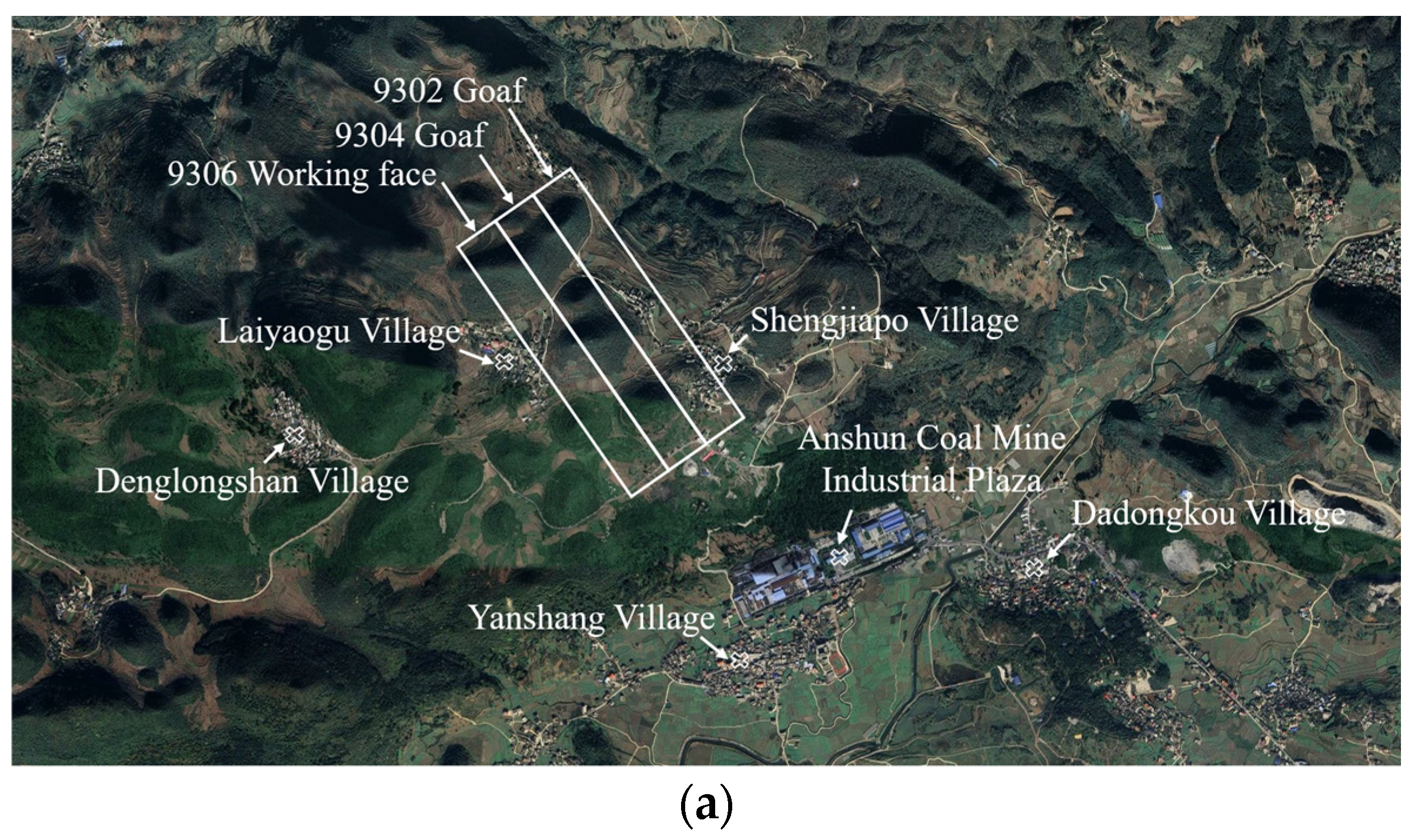
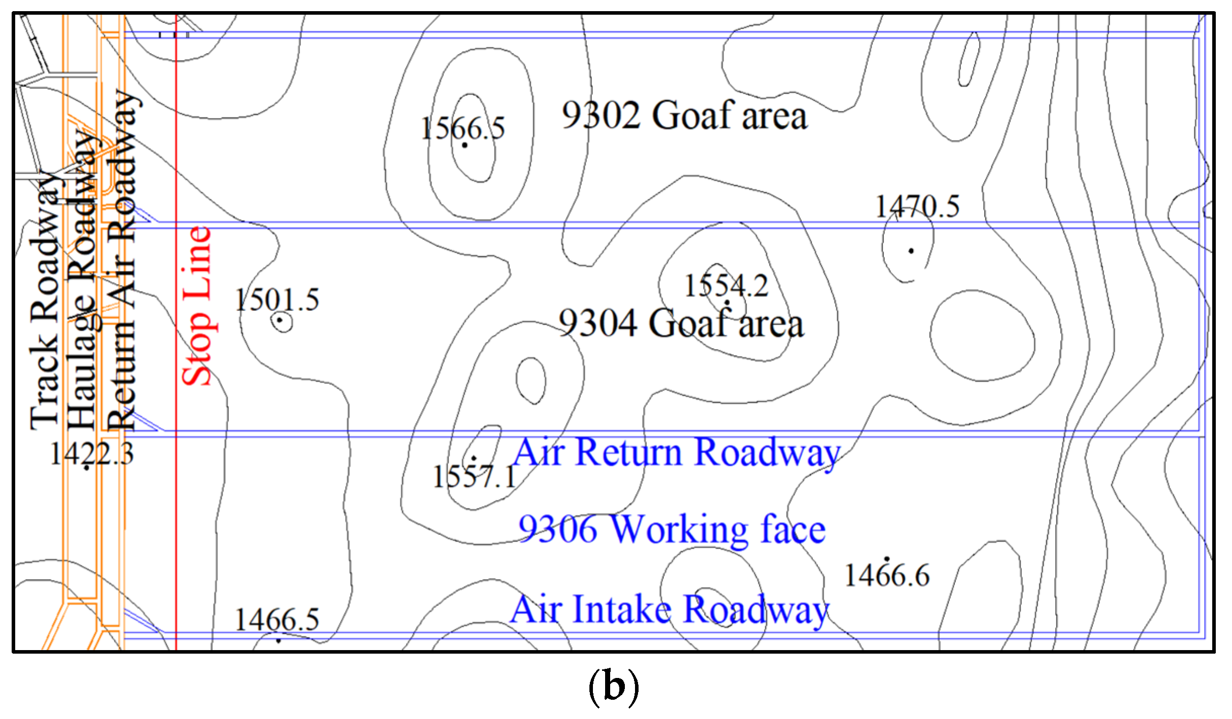
2.1. Geological Overview

The overlying surface of Anshun Coal Mine’s mining area is characterized by fault-block tectonic low-to-mid-mountain topography, as shown in Figure 1a. Within this region, the 9304 and 9306 working faces are depicted in Figure 1b. The area exhibits multiple isolated peaks, with a relative surface height difference ranging from 0 to 152 m. The burial depth of the coal seam varies between 385 and 537 m, with an average thickness of 1.53 m. The coal seam dip angle is between 2° and 4°. The immediate roof of the coal seam is composed of carbonaceous claystone, with a thickness of 5.27 m. The main roof is composed of flint limestone, with a thickness of 4.79 m. The floor of the coal seam is made of clayey sandstone, with a thickness of 3.78 m.

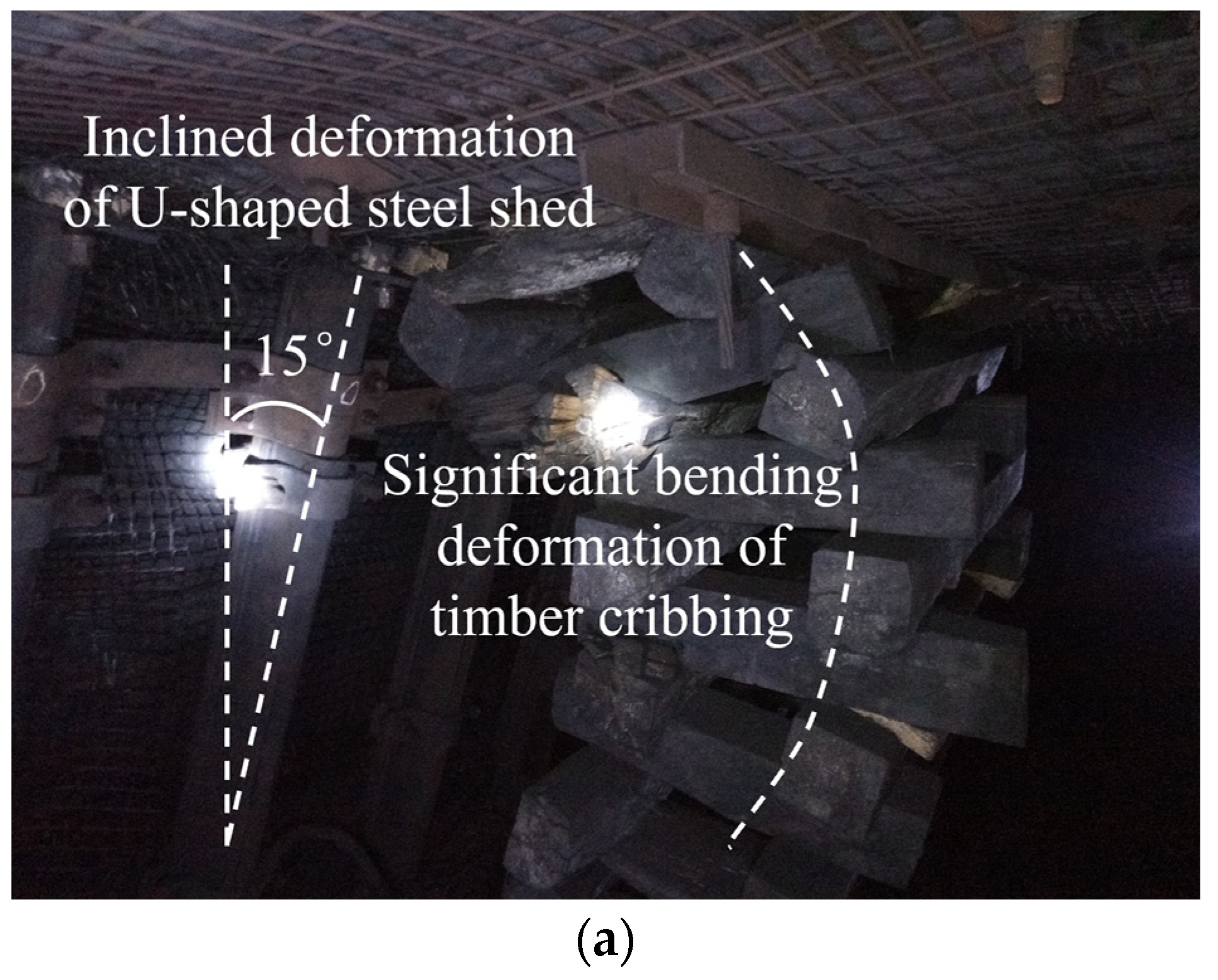
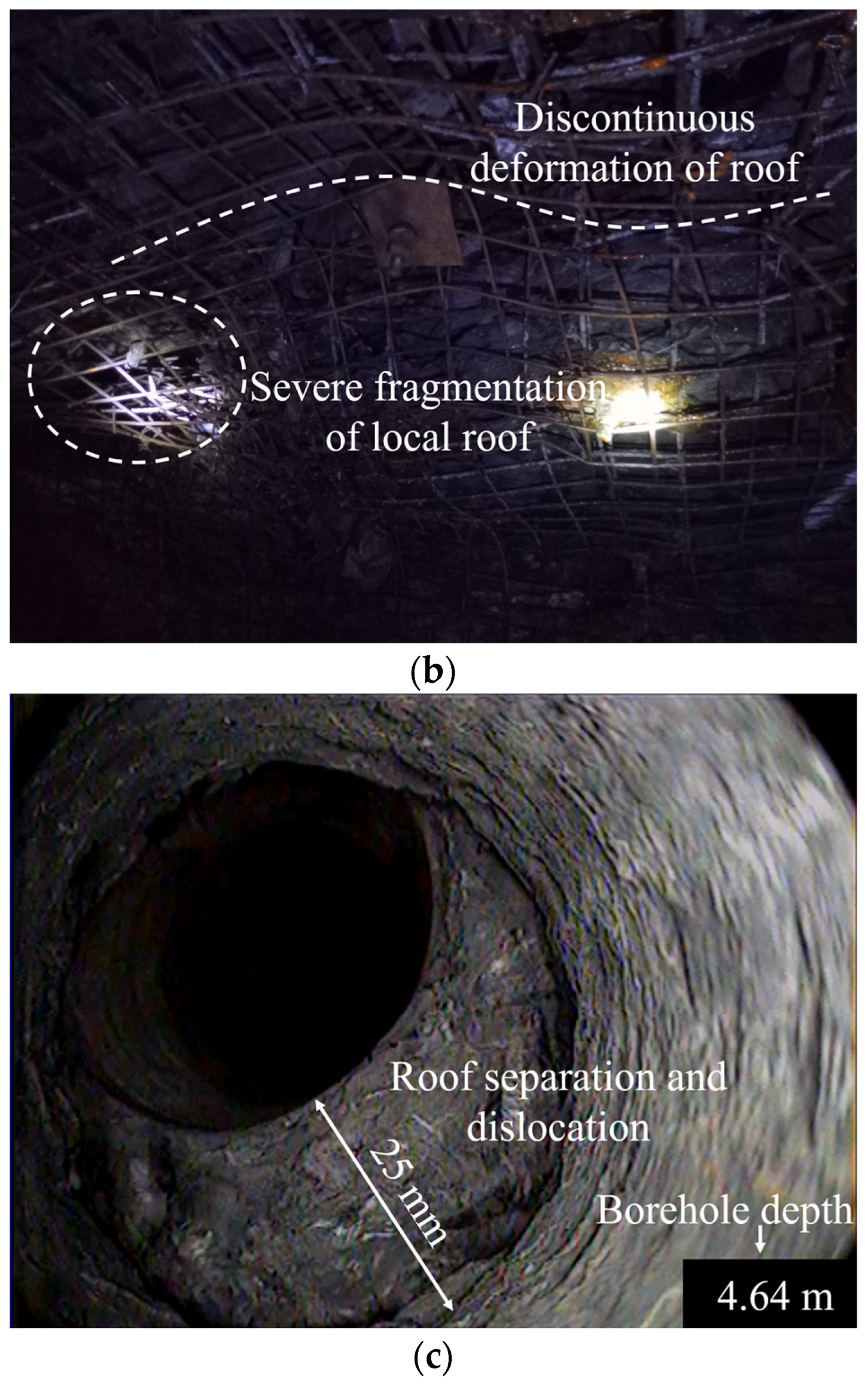
2.2. The Effect of GSER

In the 9304 working face of Anshun Coal Mine, the GSER project with roof cutting and pre-splitting was carried out in the intake roadway. The roof-cutting height was 4 m, and the roof-cutting angle was 10°. After the GSER, it was used as the return airway of the 9306 working face. It was found through field investigation that the roadway was seriously affected by the difference in original rock stress caused by the sharp change in coal seam burial depth in the karst mountainous area and the unreasonable selection of roof-cutting parameters, resulting in severe problems in roadway stability. The specific manifestations are as follows: The severe subsidence of the roof on the roof-cutting side led to obvious tilting and bending deformation of the roadside support body, as shown in Figure 2a; insufficient roof cutting resulted in the fracture line located above the roof, causing discontinuous deformation and severe local fragmentation of the retained roadway roof, as shown in Figure 2b; obvious separation and dislocation occurred at the interface between the immediate roof and the main roof, as shown in Figure 2c, indicating that insufficient roof cutting led to the roof on the goaf side not collapsing in time.

2.3. Analysis of Key Factors Affecting the Stability of Surrounding Rock in GSER with Roof Cutting

The key to GSER with roof cutting lies in making the main roof cut in such a way that the roof falls along the goaf side under the action of dynamic pressure and self-weight. When roof cutting is insufficient, the deflection of the main roof will cause severe subsidence of the roof on the roof-cutting side, resulting in severe deformation of the support body, making it difficult to ensure effective retained roadway space. At the same time, insufficient roof cutting can easily lead to the fracture line of the roof shifting upwards towards the roadway roof, causing fracture and deformation of the retained roadway roof. On the other hand, excessive roof cutting will lead to an increase in drilling depth and drilling time, causing difficulties in site construction. Excessive roof cutting may also lead to the instability of multiple layers of overlying strata, causing sudden impact deformation of the retained roadway roof under the action of dynamic pressure. In summary, considering the unique distribution characteristics and stress concentration state of the original rock stress in karst mountainous areas, it is necessary to study the relationship between key roof-cutting parameters and the stability of the surrounding rock under different burial depths to achieve the effectiveness of GSER with roof cutting and pre-splitting in karst mountainous areas.

3. Mechanical Analysis of Stress Optimization Induced by Roof Structure in GSER

3.1. Mechanical Model Construction

The key to controlling the stability of the roof in gob-side entry retention lies in adopting proactive pre-cracking measures to induce the roof structure of the roadway to break along the side of the goaf, thus achieving long-term stability of the retained roadway. The breaking of the roof of the retained roadway often occurs with the mining of the working face, and it breaks synchronously with the roof of the goaf under the influence of periodic weighting, thus forming a “masonry beam” structure. Therefore, before the roof breaks, the hard basic roof above the roadway roof can be regarded as a cantilever beam. Considering the influence of support pressure, the cantilever beam bears unevenly distributed loads. The angle between the cutting plane and the vertical direction is the cutting angle (θ), and the cutting height is (h). The mechanical model of the cantilever beam under the influence of roof cutting and pre-cracking is shown in Figure 3.
In the mechanical model, x1 represents the width of the limit equilibrium zone, m; x2 represents the width of the retained roadway, m; x3 represents the projected width of the cutting line in the horizontal direction, m; x4 represents the distance from the uncut top part to the end of the cantilever beam, m; x5 represents the distance from the limit equilibrium zone to the end of the cantilever beam, m; m represents the thickness of the coal seam, m; m1 is the thickness of the immediate roof, m; m2 represents the thickness of the main roof, m; h represents the cutting height, m; and h1 represents the height of the uncut top part, m. θ is the cutting angle, °; q1 represents the load above the cantilever beam, MPa; KγH represents the lateral supporting stress on the basic roof of the roadway, MPa; K represents the stress concentration factor; H represents the buried depth of the coal seam, m; and γ represents the bulk density of the rock, kN/m3.
To enable the cantilever beam rock block of the basic roof to collapse smoothly along the side of the goaf under the combined action of the overlying load and self-weight, the tensile stress of the uncut part should be greater than the tensile strength at that cross-section:
σ t > σ s
where σt represents the tensile stress of the uncut part, MPa, and σs represents the tensile strength of the basic roof, MPa.
The tensile stress of the uncut part can be expressed as follows:
σ t = M W
where M represents the bending moment of the uncut part, N·m, and W represents the bending section modulus at the uncut part.
The bending moment of the uncut part can be expressed as follows:
M ( x ) = M 1 ( x ) + M 2 ( x )
where M1 represents the bending moment generated by the overburden load on the cantilever beam, N·m, and M2 represents the bending moment generated by the self-weight of the cantilever beam, N·m.
To facilitate further analysis of the influence of key parameters of roof cutting on the stability control of retained roadways, the load above the cantilever beam rock block in the mechanical model is simplified as trapezoidal load q1. According to the superposition principle, the trapezoidal load q1 is equivalent to rectangular, uniformly distributed load q3 and triangular load q4, and the bending moments generated by the two loads on the uncut surface are equivalent to the trapezoidal load [40].
In the mechanical model, y represents the direction perpendicular to the main roof; x represents the direction parallel to the main roof; q1 represents the load above the cantilever beam, MPa; q3 represents the equivalent rectangular uniformly distributed load, MPa; q4 represents the equivalent triangular load, with its peak value being K·q3, MPa; and K represents the stress concentration factor.
For Figure 4a, under the trapezoidal load q1, the moment distribution is equivalent to the following:
M 1 ( x ) = M 3 ( x ) + M 4 ( x )
For Figure 4b, under the uniform load q3, the moment distribution is as follows:
M 3 ( x ) = 1 2 q 3 x 2
For Figure 4c, under the triangular load q4, the moment distribution is as follows:
M 4 ( x ) = 1 24 q 4 x 3
Under the triangular load q2, the bending moment distribution is as follows:
M 2 ( x ) = 1 2 q 2 x 2
where q2 represents the uniformly distributed load generated by the self-weight of the cantilever beam, MPa.
Therefore, the moment M distribution of the cantilever beam structure under non-uniform load is
M ( x ) = M 2 ( x ) + M 3 ( x ) + M 4 ( x ) = 1 2 q 2 x 2 + 1 2 q 3 x 2 + 1 24 q 4 x 3
According to material mechanics, the flexural section modulus of a cantilever beam can be expressed as follows:
W = b h 1 2 6 = h 1 2 6
where b represents the sectional width of the uncut roof portion of the cantilever beam, measured in meters (with a typical unit length of 1 m).
Therefore, the tensile stress in the uncut top part is
σ t = M W = 3 q 2 x 4 2 + 3 q 3 x 4 2 + 1 4 q 4 x 4 3 h 1 2
where x4 and h1 are calculated by the following formulas:
x 4 = x 5 x 1 x 2 x 3 x 3 = h · t a n θ h 1 = m 1 + m 2 h
According to the limit equilibrium theory of rock mass [41,42], the width of the limit equilibrium zone of the roadway (x1) is obtained from the following formula:
x 1 = m 2 ξ f l n K γ H + C c o t φ ξ ( p 1 + C c o t φ )
ξ = 1 + s i n φ 1 s i n φ
where K represents the stress concentration factor; H represents the buried depth of the coal seam, m; γ represents the bulk density of the rock, kN/m3; p1 represents the resistance of the support to the coal rib, MPa; m represents the thickness of the coal seam, m; C represents the cohesive force of the coal body, MPa; φ represents the internal friction angle of the coal body, °; f represents the friction coefficient between the coal seam and the roof/floor contact surface; and ξ represents the triaxial stress coefficient.
According to the theory of fracture line in the plastic limit analysis method [43], the cantilever beam length (x5) during the periodic caving process of the main roof can be obtained from the following formula:
x 5 = l l b + l 2 b 2 + 3 2
where l represents the periodic weighting step distance of the main roof, m, and b represents the length of the working face, m.

3.2. Analysis of Mechanical Model Results

The sources of the parameters in the mechanical model are listed here. According to the geological conditions of Anshun Coal Mine, the directly obtainable parameters are the following: the working face length b is 180 m, the coal seam thickness m is 1.8 m, the gob-side entry retaining width x2 is 6 m, the thickness of the immediate roof m1 is 5.3 m, and the thickness of the main roof m2 is 4.8 m. Laboratory experiments were conducted on coal and rock samples obtained from on-site borehole coring to determine the coal cohesion C as 1 MPa and the internal friction angle φ of coal as 20°. Based on empirical values and references, the friction coefficient f was determined as 0.1, and the unit weight of rock γ was 25 kN/m3. Finally, through data collection and analysis from on-site hydraulic-support-pressure sensors and surrounding-rock-stress sensors, the average periodic weighting interval l was obtained as 18 m, the resistance of the support to the coal rib p1 was 0.1 MPa [35,41], the stress concentration factor K was 2.5, the load q2 was 0.12 MPa, the load q3 was 0.4 MPa, and the load q4 was 1 MPa. By substituting the aforementioned parameter values into Equations (9)–(14), the relationships between the tensile stress in the uncut roof section and the cutting height, cutting angle, and coal seam burial depth were obtained as follows:
x 4 = 14.31 4.41 l n ( 0.01076 H + 0.47307 ) h t a n θ σ t = 0.48 x 4 2 + 0.25 x 4 3 ( 10.06 h ) 2
Affected by the unique geological characteristics of karst mountainous areas, the working face will continuously pass through multiple independent peaks during the mining process, resulting in significant changes in the buried depth of the working face. The resulting characteristics of roof-stress distribution will significantly impact the selection of roof-cutting parameters and the stability of the retained roadway. The coal seam burial depth of the 9306 working face in Anshun Coal Mine ranges from 385 to 537 m, and the sum of the thickness of the overlying immediate roof and the main roof is 10.06 m. Therefore, the coal seam burial depths are set at 350 m, 400 m, 450 m, 500 m, and 550 m; the roof-cutting heights are set at 4 m, 5 m, 6 m, 7 m, and 8 m; and the roof-cutting angles are set at 0°, 5°, 10°, 15°, 20°, 25°, 30°, 35°, 40°, 45°, and 50°. The coal seam burial depth (H), roof-cutting height (h), and roof-cutting angle (θ) are substituted into Equation (14) to plot the evolution characteristics of the tensile stress in the uncut part of the main roof under the influence of burial depth and roof-cutting parameters (Figure 5), where the tensile strength of the main roof is 7.2 MPa.
As can be seen from Figure 5a, there is a relatively clear positive correlation between the tensile stress in the uncut part of the main roof and the cutting height. As the cutting height increases, the length of the uncut part gradually decreases, resulting in a decrease in the bending-section coefficient of the cantilever beam and a gradual increase in tensile stress. However, when the cutting angle exceeds 30°, the effect of further increasing the cutting height on the tensile stress is no longer significant. There is a relatively clear negative correlation between the tensile stress in the uncut part of the main roof and the cutting angle within a certain range. As the cutting angle increases, the bending-section coefficient of the cantilever beam gradually increases, and the tensile stress gradually decreases to tend towards 0 MPa. The higher the cutting height, the more obvious the degree of reduction. When the cutting angle is 0°, the tensile stress in the uncut part of the main roof reaches its peak. Therefore, during actual construction, increasing the cutting height or decreasing the cutting angle within a certain range can significantly increase the tensile stress in the uncut part of the main roof, which helps the cantilever roof on the goaf side to break smoothly under the action of tensile stress. There is a negative correlation between the tensile stress in the uncut part of the main roof and the burial depth of the coal seam. From the analysis of the mechanical model, as the burial depth of the coal seam increases, the width of the limit equilibrium zone of the solid coal rib increases, leading to a decrease in the length of the cantilever roof and, subsequently, a decrease in tensile stress. Therefore, it is necessary to select suitable roof-cutting parameters in different coal seam burial depth areas to avoid problems such as difficulty in the collapse of the goaf-side roof due to insufficient or excessive cutting or excessively long construction cycles for cutting-roof drilling.
Analyzing Figure 5b, it can be seen that the tensile stress in the uncut part of the main roof is comprehensively influenced by the burial depth of the coal seam, the cutting height, and the cutting angle. Analyzing the state of sufficient roof cutting, where the tensile stress in the uncut part of the main roof is greater than the tensile strength, we find that when the cutting angle and cutting height are kept constant, for every 50 m decrease in the coal seam burial depth within the range from 350 m to 500 m, the tensile stress in the uncut part of the main roof will increase by approximately 16%–27%. The increase becomes more significant with the decrease in cutting angle and the increase in cutting height. When the coal seam burial depth and cutting angle are kept constant, for every 1 m increase in the cutting height within the range from 4 m to 8 m, the tensile stress in the uncut part of the main roof will increase by approximately 28%–54%. The increase becomes more significant with the decrease in coal seam burial depth and the increase in cutting angle. When the coal seam burial depth and cutting height are kept constant, for every 5° decrease in the cutting angle within the range from 0° to 50°, the tensile stress in the uncut part of the main roof will increase by approximately 20%–35%. The increase becomes more significant with the decrease in coal seam burial depth and the increase in cutting height. Judging from the increase in tensile stress in the uncut part of the main roof, the overall impact of the cutting height is relatively significant, followed by the cutting angle. The burial depth of the coal seam also has an impact on the tensile stress of the main roof, especially in relatively shallow burial depth areas. Considering that actual cutting parameters are usually selected as integers, under different burial depth conditions, we can fix the cutting height and cutting angle as integers and further study the critical value and reasonable range of key cutting parameters by taking the tensile strength of the main roof as the threshold.
By fixing the cutting angle and cutting height as integers and substituting them into Equation (14), with the tensile strength of the main roof as the threshold, the reasonable range of critical cutting parameters under different burial depths is obtained, as shown in Figure 6. By analyzing Figure 6, we can see that the reasonable range of cutting parameters exhibits a fan-shaped distribution characteristic. As the burial depth of the coal seam increases, the fan-shaped area of reasonable cutting parameters gradually decreases. With the increase in cutting height, the selectable range of cutting angles gradually increases. When the cutting height is below 4.5 m, effective roof cutting cannot be achieved. When the cutting height is between 4.5 and 8 m, the selectable range of cutting angles is from 0 to 28.5°. As the cutting angle increases, the selectable range of cutting heights gradually decreases. When the cutting angle is 30° and the cutting height tends to 10 m, it is similar to the thickness of the main roof. Taking 7.2 MPa tensile strength of the main roof as the critical value and an average coal seam burial depth of 450 m as an example, the critical values of cutting parameters are shown in Table 1.

4. Simulation Analysis of Key Roof-Cutting Parameters for GSER

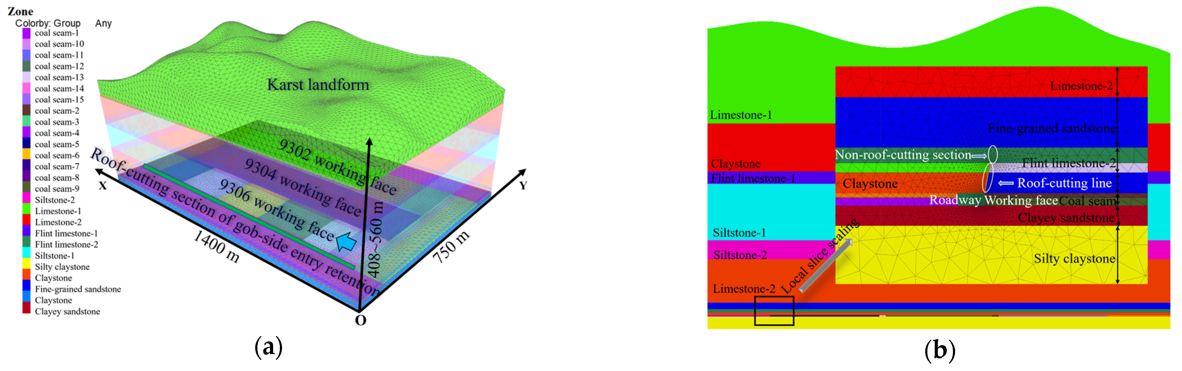
4.1. Simulation Scheme and Model Construction

Taking the 9306 working face of Anshun Coal Mine as the research object, a three-dimensional numerical model of FLAC 3D is constructed based on the topographical characteristics of the karst mountainous area. Combining with the previous research, reasonable roof-cutting parameters at different burial depths were selected to determine the numerical simulation scheme, as shown in Table 2. The deformation and stress distribution characteristics of the roof in GSER under different burial depths and different roof-cutting parameters were analyzed.
Using FLAC3D 5.0 software, a 3D numerical model with a length of 1400 m, a width of 750 m, and a height of 408~560 m was constructed. The grid size ranged from 0.2 to 20 m, and the total number of grid cells in the model was 548,682. The model calculations adopted the Mohr–Coulomb criterion with displacement boundary constraints applied to the bottom and sides and an overall gravitational acceleration of 9.8 m/s2. A 100 m boundary coal pillar was left around the model. An example of the 3D model and the simulation scheme are shown in Figure 7. The model excavated the 9302 working face, the 9304 working face, the roadway of the 9306 working face, roof cutting of the 9306 working face, and the 9306 working face, sequentially. Among them, the roadway of the 9306 working face was 6 m wide and 2.2 m high, with a roof-cutting seam width of 0.05 m. Excavation was gradually carried out until the operation reached equilibrium.
Field drilling and coring were conducted on the surrounding rock of the intake roadway at the 9306 working face of Anshun Coal Mine, and rock samples were prepared according to standardized requirements. In the laboratory, standardized rock samples underwent a series of tests including uniaxial compression, triaxial compression, Brazilian splitting, shearing, and bulk density measurements. These tests were conducted to obtain the physical and mechanical parameters of the coal and rock mass in the study area, such as bulk modulus, shear modulus, tensile strength, cohesion, internal friction angle, and density, as shown in Table 3.

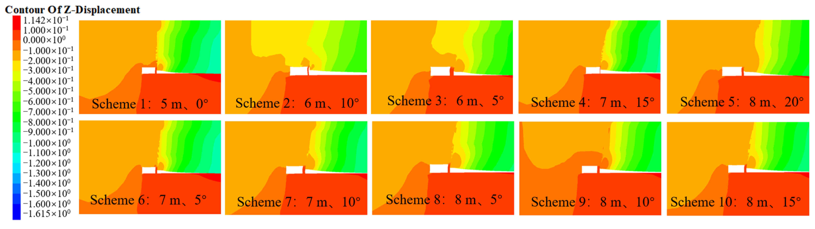
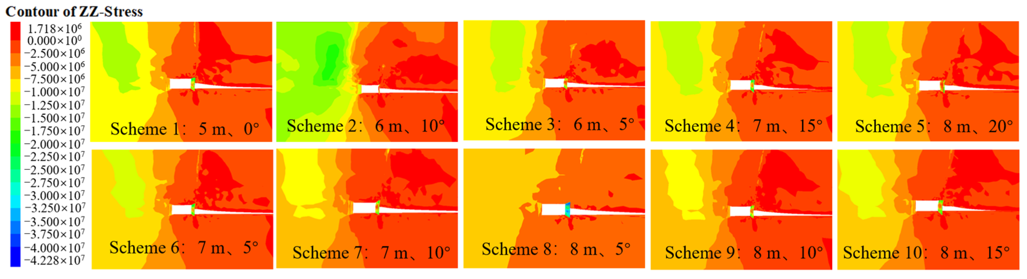
4.2. Analysis of Simulation Results

The deformation and stress distribution of the surrounding rock along the gob-side entry retention under different roof-cutting schemes are shown in Figure 8 and Figure 9. As can be seen from Figure 8, after the roof cutting and entry retaining, a distinct fracture line is formed along the cutting line of the roof, and there is a significant difference in vertical displacement between the two sides of the fracture line, indicating that the cantilever structure of the roadway roof has been effectively cut off through roof cutting and pre-splitting, thus playing a role in controlling the displacement of the surrounding rock of the roadway. Among them, the subsidence of the roadway roof near the goaf side is significantly greater than that of the solid coal side, showing a trapezoidal subsidence state. Therefore, reinforcement support is needed on the side of the gob-side entry retention near the goaf to achieve overall stability control of the roadway roof.
As shown in Figure 9, after top-cutting and gob-side entry retaining, the vertical stress in the roof of the roadway is significantly released, and the stress is transferred towards the deep part of the solid coal side as a whole. Locally, affected by the deflection of the roof strata, the stress is concentrated at the top of the top-cutting crack, thereby avoiding the shallow stress concentration on the solid coal side of the roadway caused by the untimely cutting and collapse of the roof on the goaf side. If the supporting capacity of the solid coal side is insufficient to cope with the concentrated stress, it will lead to rib spalling and extrusion deformation on the solid coal side of the roadway during the process of gob-side entry retention. In severe cases, the concentrated release of accumulated energy on the solid coal side or rockburst accidents may occur, thereby threatening the stability and safety of the gob-side entry retention. Therefore, the numerical simulation indicates that reasonable top-cutting parameters can effectively cut off the mechanical connection between the roof of the retained roadway and the goaf side, reduce the vertical stress on the roadway roof, and force the concentrated stress on the solid coal side to transfer towards the deep part, significantly optimizing the stress state of the surrounding rock of the retained roadway and facilitating long-term stability control of the retained roadway roof.
In the numerical simulation, measuring lines were arranged above the coal seam using the built-in commands of FLAC3D to monitor the vertical stress, vertical displacement, and lateral supporting stress of the gob-side entry retaining roof. Specifically, the monitoring lines for roof stress and lateral supporting stress of the roadway were horizontally arranged at the intersection of the basic roof and the immediate roof of the roadway, i.e., 5.3 m above the coal seam. The displacement monitoring line was horizontally arranged below the immediate roof, i.e., on the surface of the roadway. The peak values of roof vertical displacement and vertical stress from each numerical simulation scenario were extracted and plotted in Figure 10. An analysis of Figure 10 reveals that within the same burial depth range, achieving complete roof cutting is more feasible by increasing the cutting height and decreasing the cutting angle. Comparing scenarios 3, 4, and 5, as the cutting height increases, the selectable range of cutting angles gradually widens, and the displacement and stress peak of the retained roadway roof gradually decrease, albeit with diminishing returns. Therefore, the benefits gained from increasing the cutting height gradually diminish. Within the same burial depth range, as the cutting angle increases, the vertical stress shifts towards the solid coal side, and both the vertical displacement and stress peak of the retained roadway roof show a decreasing trend, albeit with diminishing reductions. When comparing various scenarios, the maximum displacement and stress peak of the roof are significantly larger when the cutting angle is 0° or 5°, indicating that smaller cutting angles result in greater sliding resistance between the cuts, making it difficult for the gob-side roof to collapse completely under dynamic pressure. Additionally, the deflection of the roof cantilever structure contributes to larger displacement and stress on the retained roadway roof. As the cutting angle increases, the peak stress concentration on the solid coal side gradually increases, suggesting that blindly increasing the cutting angle does not continuously enhance the benefits. Furthermore, due to field construction constraints, increasing the cutting angle prolongs the drilling cycle, significantly affecting the progress of underground roof-cutting and pre-splitting projects.
Stability analysis of the roadway cross-section in different cutting scenarios of the 9306 working face was conducted using the strength reduction method. According to this method, the mechanical parameters of the rock mass (internal friction angle C and cohesion φ) were altered until the limit equilibrium state was reached, and the reduction factor at this point was defined as the safety factor [44,45]. Under different simulation scenarios, the reduction of the surrounding-rock parameters of the roadway cross-section started from 1 and increased incrementally by 0.1. When the displacement growth rate of the control points suddenly increased, indicating instability of the roadway, the reduction was performed incrementally by 0.02 as the instability stage approached. The safety factors of the roadway under different scenarios are summarized in Table 4. Analysis revealed that by selecting reasonable roof-cutting parameters, all scenarios could ensure that the safety factor of the roadway was above 1.68. Within the same burial depth range, as the cutting height and cutting angle increased, the safety factor of the roadway gradually increased, but the rate of increase gradually decreased. Therefore, when determining the roof-cutting parameters, it is necessary to comprehensively consider the balance between drilling construction costs and roadway stability.
Based on theoretical analysis and the numerical simulation results, considering the variability in burial depth within the coal seam region of the karst mountainous area, a cutting angle of 10° is able to effectively ensure the long-term stability of the retained roadway roof without being limited by the duration of drilling. Specifically, when the burial depth is below 400 m, Scenario 2 is suitable; when the burial depth is between 400 m and 500 m, Scenario 7 is appropriate; and when the burial depth is above 500 m, Scenario 9 is recommended.

5. Engineering Practice

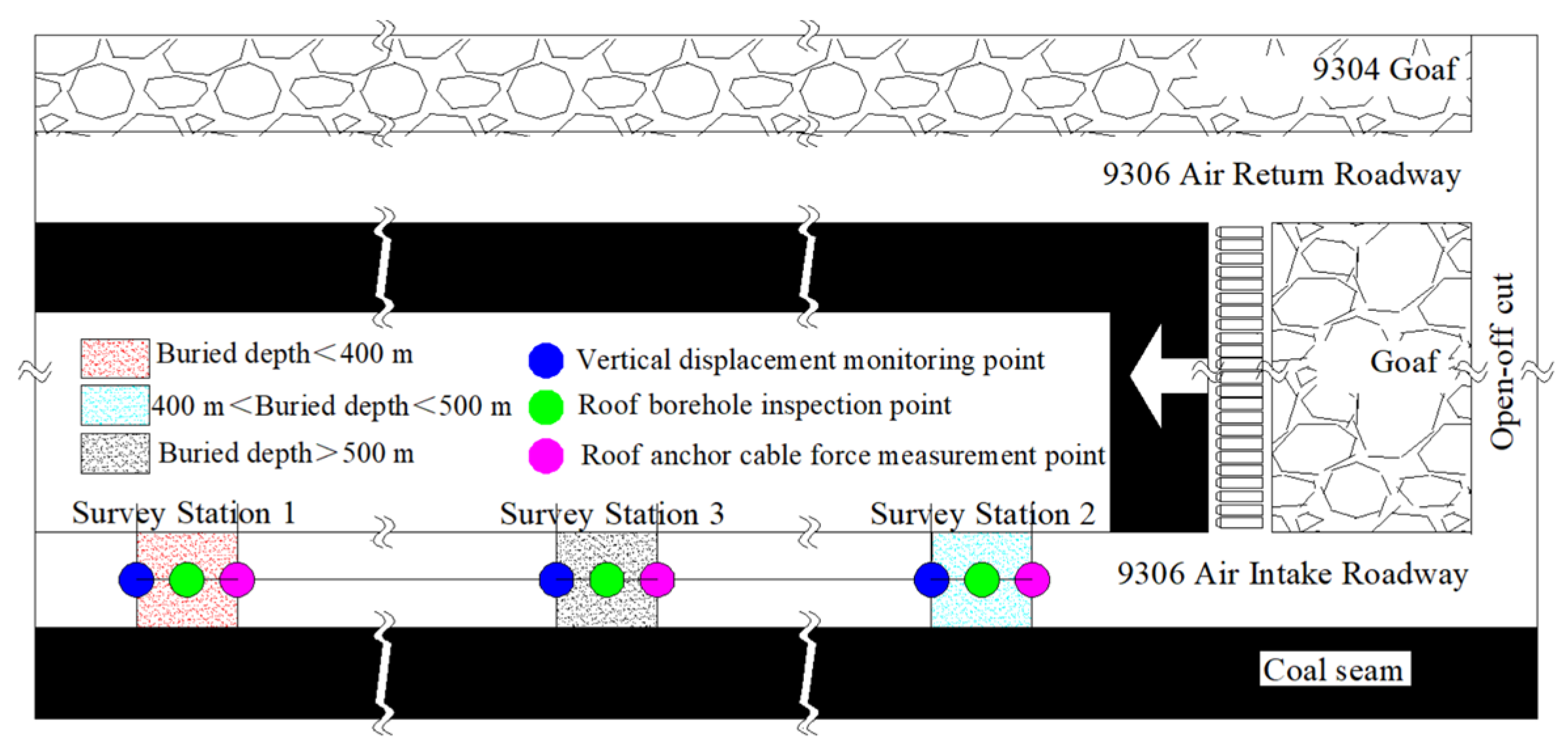
5.1. Field Monitoring Plan

Incorporating the aforementioned research, the engineering practice of roof cutting and roadway retention was implemented in different burial depth sections of the intake roadway at the 9306 working face. Schemes ②, ⑦, and ⑨ were selected for monitoring the stability of surrounding rock in the retained roadway with roof cutting, targeting sections with burial depths of less than 400 m, between 400 m and 500 m, and greater than 500 m, respectively. The cross-sectional deformation of the roadway was monitored using the cross-sectional layout method, while the tension of anchor cables was collected with an anchor cable dynamometer. A borehole camera was employed to detect the internal fracture condition of the roof. The overall stability of the roadway cross-section was assessed by observing the deformation degree of the support structure. Based on the aforementioned four monitoring results, an evaluation of the final roadway retention effect at the 9306 working face was conducted. The on-site monitoring arrangement is illustrated in Figure 11.

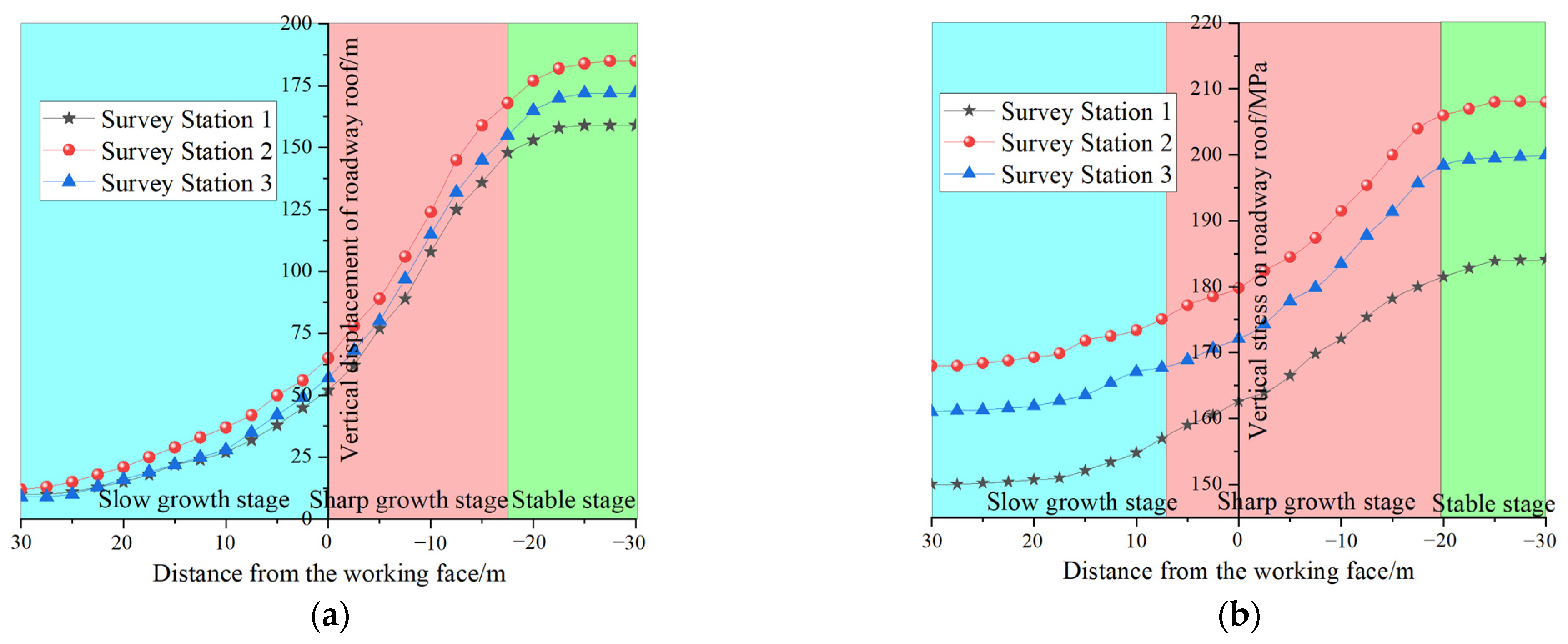
5.2. Analysis of Monitoring Results

The roof deformation of the 9306 working face at different burial depths is shown in Figure 12a. The analysis reveals that as the working face advances, the vertical displacement of the roof exhibits a gradual increase, followed by a sharp increase, and finally stabilizes. The peak vertical displacements of the three monitored sections are all located on the roof-cutting side and gradually increase with increasing burial depth, with values of 159 mm, 172 mm, and 185 mm, respectively. These values are similar to the numerical simulation results of 182 mm, 185 mm, and 194 mm, with an error rate maintained between 5% and 14%. Notably, when compared to the designed height of the roadway of 2.2 m, the maximum roof deformation accounts for approximately 8.4%, indicating that the deformation of the roof at different burial depths has been effectively controlled through reasonable roof-cutting parameters.
The stress on the roof anchor cables on the roof-cutting side in different buried depth sections of the 9306 working face is shown in Figure 12b. The analysis reveals that the stress on the anchor cables also exhibits a slow growth phase, a rapid growth phase, and then tends to stabilize, which is basically consistent with the roof movement state. Affected by the abutment pressure in front of the working face, the stress on the anchor cables gradually increases. As it gradually approaches the working face, influenced by the violent roof movement, the stress increase on the anchor cables gradually rises. After entering the entry retention section for 25 m, the stress on the anchor cables gradually begins to stabilize. The peak stress values of the anchor cables in the three monitoring sections also gradually increase with greater buried depth, reaching 184 KN, 200 KN, and 208 KN, respectively, all within the allowable range for anchor cable use. This indicates that reasonable roof-cutting parameters have basically achieved stress optimization of the retained roadway roof in different buried depth sections.
The overall effect of the entry retention in the air intake roadway of the 9306 working face is shown in Figure 13. From the perspective of the on-site effect, the internal and external parts of the roadway roof, the roadside support body, and the solid coal rib are relatively intact, with no obvious issues such as roof delamination, local roof fragmentation, or damage to the roadside support. The overall effect of entry retention is relatively good, indicating that the stability control of the surrounding rock in the GSER has been achieved by adopting reasonable roof-cutting parameters in different buried depth sections. This verifies the rationality of the theoretical calculations, numerical analysis, and roof-cutting scheme mentioned earlier.

6. Conclusions

(1)
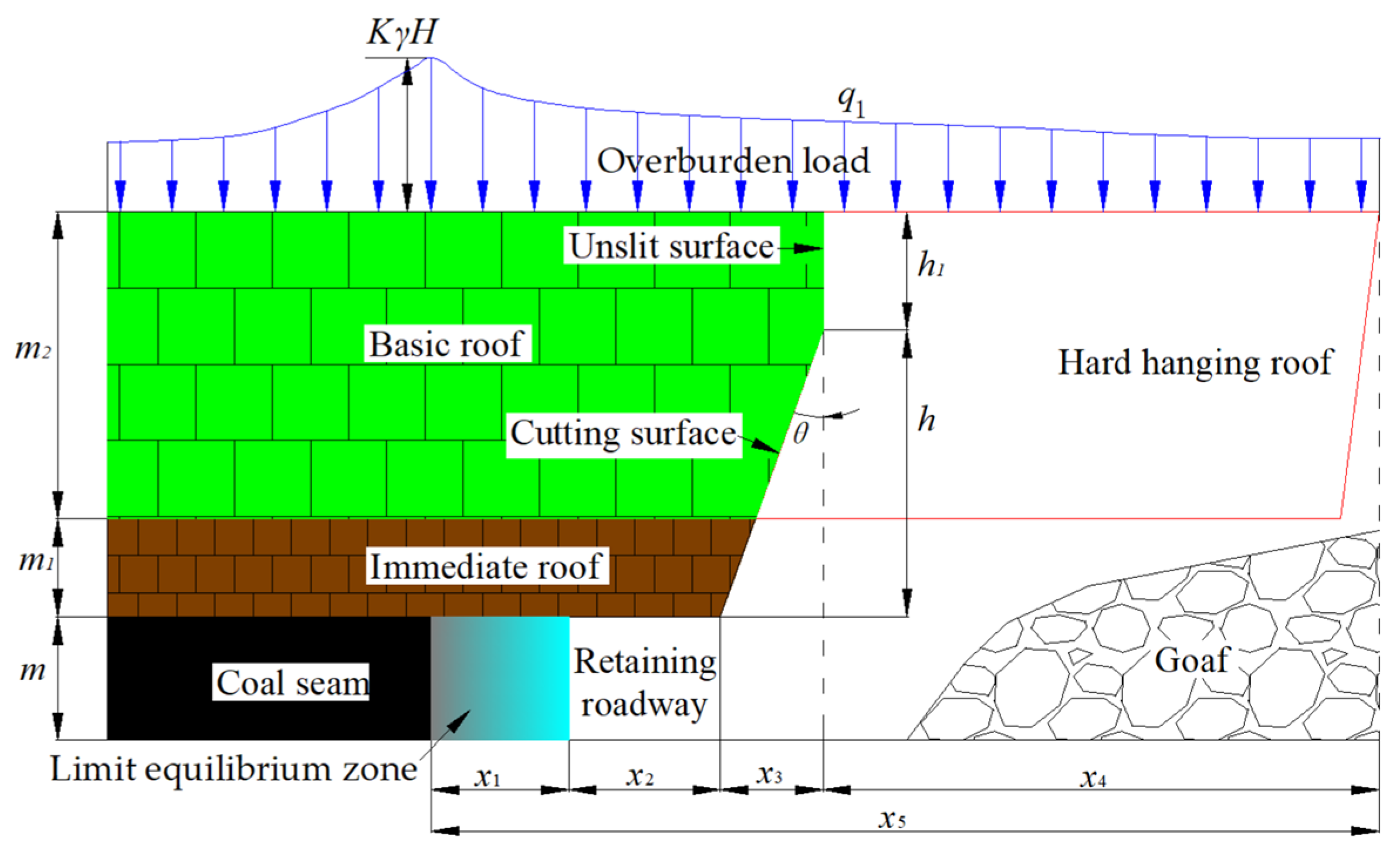
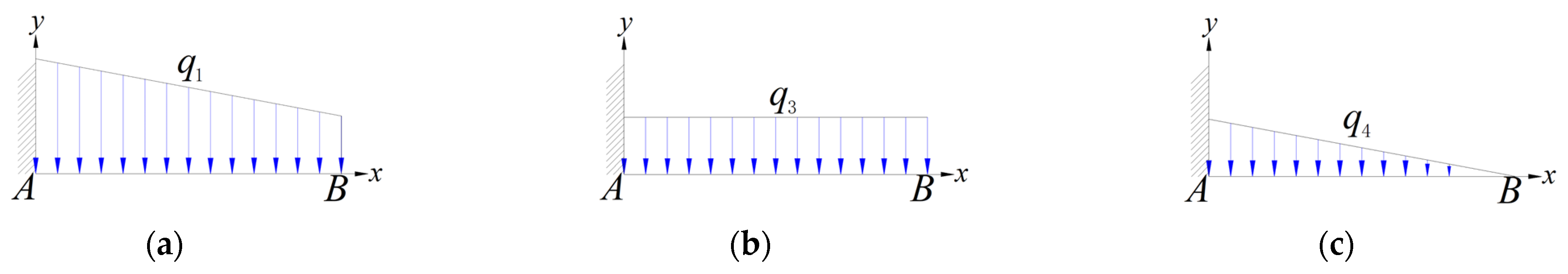
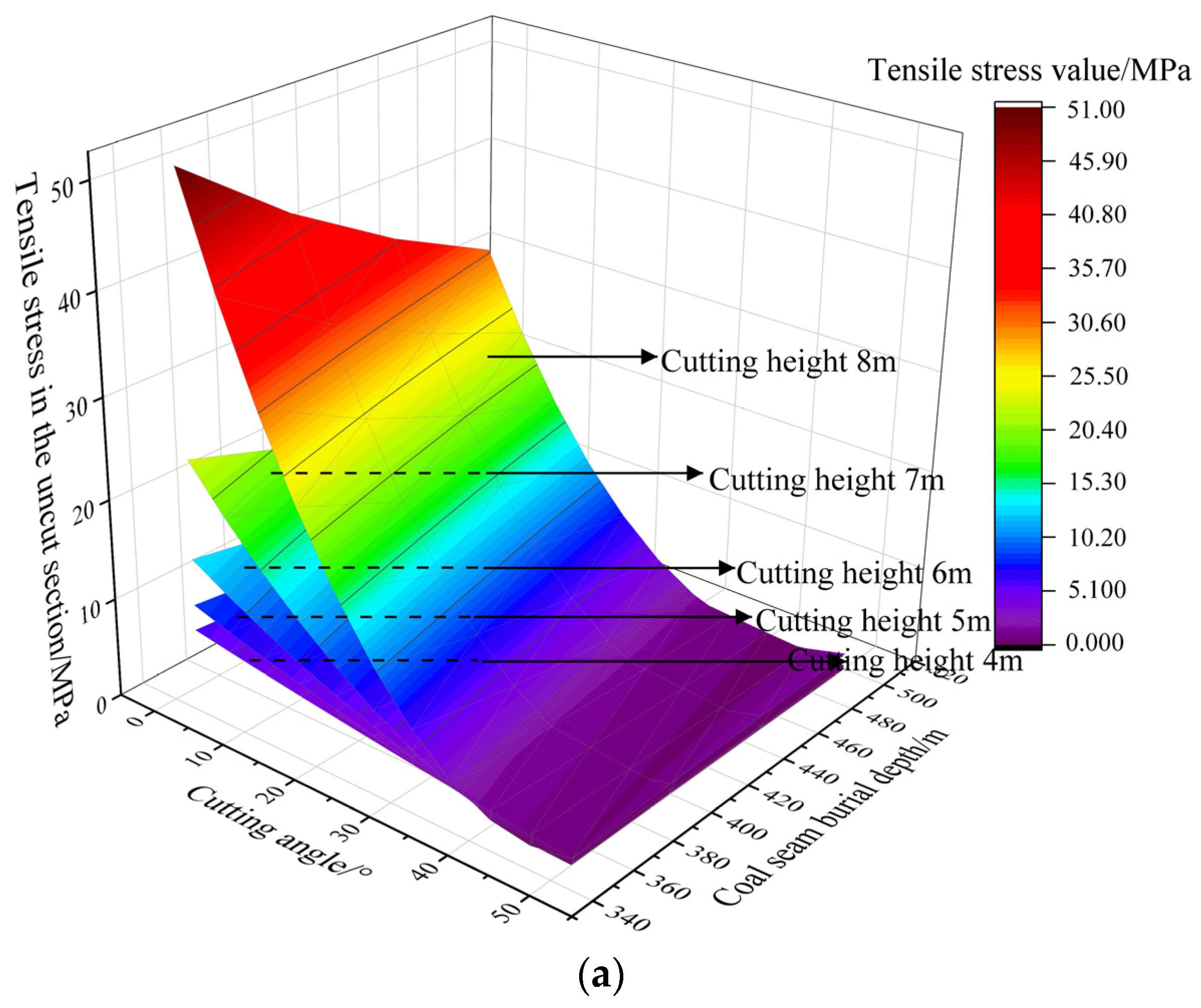
The clarification of the gob-side entry retention and roof-cutting parameters under typical geological conditions in karst mountainous areas is crucial for the stability of the surrounding rock. Based on this, by integrating the variation characteristics of coal seam burial depth and the non-uniform load distribution state of the roof in karst mountainous areas, a mechanical model of the cantilever beam structure for gob-side entry retention and roof cutting is constructed. By introducing the theory of limit equilibrium, the superposition principle, and fracture line theory, the differentiated stress distribution of the roof caused by coal seam burial depth is correlated with the parameters of roof-cutting height and angle. Taking the geological conditions of Anshun Coal Mine as an example, by substituting relevant parameters and comparing the increments of tensile stress under burial depth intervals of 50 m, roof-cutting height intervals of 1 m, and roof-cutting angle intervals of 5°, it is found that the influence of roof-cutting height > the influence of roof-cutting angle > the influence of coal seam burial depth. Considering the impact of the correlation among the three factors on the long-term stability of gob-side entry retention, it is necessary to select appropriate roof-cutting parameters in different coal seam burial depth areas to avoid insufficient or excessive roof-cutting issues.
(2)
Taking the tensile strength of 7.2 MPa of the main roof as the threshold, the critical values and reasonable ranges of roof-cutting height and roof-cutting angle under different burial depths are provided. The reasonable range of roof-cutting parameters exhibits a fan-shaped distribution feature. As the coal seam burial depth increases, the fan-shaped zone of reasonable roof-cutting parameters gradually decreases. As the roof-cutting height increases, the selectable range of roof-cutting angles gradually increases. Based on the geological conditions of Anshun Coal Mine, it is concluded that effective roof cutting cannot be achieved when the roof-cutting height is less than 4.5 m. When the roof-cutting height is between 4.5 and 8 m, the selectable range of roof-cutting angles is between 0 and 28.5°.
(3)
Through three-dimensional numerical simulation analysis, the displacement and stress evolution characteristics of the surrounding rock of the retained roadway under different roof-cutting parameter schemes within a reasonable range were explored. It was found that a smaller cutting angle results in greater sliding resistance between the cuts, leading to larger displacement and stress on the retained roadway roof. Conversely, a larger cutting angle prolongs the drilling cycle, impacting the progress of underground construction. Analyzing the safety factor of the roadway using the strength reduction method, it was observed that within the same burial depth range, as the cutting height and cutting angle increase, the safety factor of the roadway gradually increases, but the rate of increase gradually decreases. Therefore, when determining the roof-cutting parameters, it is essential to comprehensively consider the balance between drilling construction costs and roadway stability. Overall, a cutting angle of 10° is considered reasonable. Furthermore, corresponding roof-cutting height schemes of 6 m, 7 m, and 8 m were proposed for burial depths of less than 400 m, between 400 m and 500 m, and greater than 500 m, respectively. The roadway stability coefficients under these three schemes are higher than those of other schemes within the same burial depth range, with values of 2.02, 1.96, and 1.88, respectively.
(4)
Industrial practice was conducted in a typical section of Anshun Coal Mine, and the effect of the retained roadway was verified in terms of the roof displacement, the stress state of the anchor cables on the cutting side, the integrity of the roof surrounding rock, and the deformation characteristics of the support structures in different buried depth sections of the GSER. It was concluded that all three roof-cutting schemes could effectively ensure the stability of the surrounding rock in the retained roadway, thus verifying the rationality of the previous theoretical calculations, numerical analysis, and roof-cutting schemes.

Author Contributions

Conceptualization, Y.L. and W.G.; methodology, G.F.; software, Y.L. and W.G.; validation, Y.L., W.Y. and Y.C.; formal analysis, Y.L.; investigation, X.Y. and X.H.; data curation, W.G. and X.Y.; writing—original draft preparation, Y.L. and X.H.; writing—review and editing, G.F. and Y.C. All authors have read and agreed to the published version of the manuscript.

Funding

The research was financially supported by the National Natural Science Foundation of China (No. 52204161), the Jiangsu Funding Program for Excellent Postdoctoral Talent (Nos. 2022ZB511 and 2023ZB517), and the Fundamental Research Funds for the Central Universities (Nos. 2022QN1008 and 2021ZDPY0226).

Institutional Review Board Statement

Not applicable.

Informed Consent Statement

Not applicable.

Data Availability Statement

Data are contained within the article.

Conflicts of Interest

The authors declare no conflicts of interest. Author Yutao Liu was employed by the company Guizhou Yuneng Investment Co., Ltd. The remaining authors declare that the research was conducted in the absence of any commercial or financial relationships that could be construed as a potential conflict of interest.

References

  1. Gabrovšek, F.; Knez, M.; Kogovšek, J.; Mihevc, A.; Mulec, J.; Perne, M.; Petrič, M.; Pipan, T.; Prelovšek, M.; Slabe, T.; et al. Development challenges in karst regions: Sustainable land use planning in the karst of Slovenia. Carbonates Evaporites 2011, 26, 365–380. [Google Scholar] [CrossRef]
  2. Babets, D.; Sdvyzhkova, O.; Hapieiev, S.; Shashenko, O.; Prykhodchenko, V. Multifactorial analysis of a gateroad stability at goaf interface during longwall coal mining-A case study. Min. Miner. Depos. 2023, 17, 9–19. [Google Scholar] [CrossRef]
  3. Malkowski, P.; Ostrowsk, L. Convergence monitoring as a basis for numerical analysis of changes of rock-mass quality and hoek-brown failure criterion parameters due to longwall excavation. Arch. Min. Sci. Arch. Min. Sci. 2023, 64, 93–118. [Google Scholar] [CrossRef]
  4. Hou, C.; Li, X. The stability principle of large and small structures of surrounding rock in gob-side entry driving for fully mechanized top coal caving mining. J. China Coal Soc. 2001, 1, 1–7. [Google Scholar] [CrossRef]
  5. Zhang, Y.; Cui, B.; Wang, Y.; Zhang, S.; Feng, G.; Zhang, Z. Evolution Law of Shallow Water in Multi-Face Mining Based on Partition Characteristics of Catastrophe Theory. Fractal Fract. 2023, 7, 779. [Google Scholar] [CrossRef]
  6. Zhang, D.; Ma, L.; Feng, G. The technology of gob-side entry retention with in-situ backfilling in fully mechanized top-coal caving mining roadways. Chin. J. Rock Mech. Eng. 2005, 7, 1164–1168. [Google Scholar] [CrossRef]
  7. He, M.; Gao, Y.; Yang, J. Research on the Technology of Spontaneous Roadway Formation without Coal Pillars Using Energy-Concentrated Slotting and Its Impact on the Evolution of Surrounding Rock Stress. Chin. J. Rock Mech. Eng. 2017, 36, 1314–1325. [Google Scholar] [CrossRef]
  8. Smoliński, A.; Malashkevych, D.; Petlovanyi, M.; Rysbekov, K.; Lozynskyi, V.; Sai, K. Research into Impact of Leaving Waste Rocks in the Mined-Out Space on the Geomechanical State of the Rock Mass Surrounding the Longwall Face. Energies 2022, 15, 9522. [Google Scholar] [CrossRef]
  9. Malashkevych, D.; Petlovanyi, M.; Sai, K.; Zubko, S. Research into the coal quality with a new selective mining technology of the waste rock accumulation in the mined-out area. Min. Miner. Depos. 2022, 16, 103–114. [Google Scholar] [CrossRef]
  10. Gao, H.; Gao, Y.; Wang, J.; Fu, Q.; Qiao, B.; Wei, X.; Zhang, X. Study on Bidirectional Blasting Technology for Composite Sandstone Roof in Gob-Side Entry-Retaining Mining Method. Appl. Sci. 2021, 11, 7524. [Google Scholar] [CrossRef]
  11. He, M.; Zhu, G.; Guo, Z. Longwall mining “cutting cantilever beam theory” and 110 mining method in China—The third mining science innovation. Chin. J. Rock Mech. Geotech. Eng. 2015, 5, 10. [Google Scholar] [CrossRef]
  12. Yang, J.; He, M.; Cao, C. Design principles and key technologies of gob side entry retaining by roof pre-fracturing. Tunn. Undergr. Space Technol. 2019, 90, 309–318. [Google Scholar] [CrossRef]
  13. Ma, Z.; Zhang, D.; Cao, Y. Study of Key Technology of Gob-Side Entry Retention in a High Gas Outburst Coal Seam in the Karst Mountain Area. Energies 2022, 15, 4161. [Google Scholar] [CrossRef]
  14. Hu, J.; He, M.; Wang, J. Key Parameters of Roof Cutting of Gob-Side Entry Retaining in a Deep Inclined Thick Coal Seam with Hard Roof. Energies 2019, 12, 934. [Google Scholar] [CrossRef]
  15. Boothukuri, V.; Bhattacharjee, R.; Panigrahi, D.; Benerjee, G. Impact of geo technical factors on strata behavior in longwall panels of Godavari Valley coal field-a case study. Int. J. Min. Sci. Technol. 2019, 29, 7. [Google Scholar] [CrossRef]
  16. Liu, Z.; Ma, Z.; Kazanin, O.I.; Gong, P.; Li, Y.; Ni, X. Deformation Control Technology of Gob-Side Entry Retaining with Large Volume CFST Roadway Side Support in Top-Coal Caving Longwall and Stability Analysis: A Case Study. Appl. Sci. 2023, 13, 8610. [Google Scholar] [CrossRef]
  17. Gong, S.; Tan, Y.; Liu, Y. Application of Presplitting Blasting Technology in Surrounding Rock Control of Gob-Side Entry Retaining with Hard Roof: A Case Study. Adv. Mater. Sci. Eng. 2021, 2021, 1318975. [Google Scholar] [CrossRef]
  18. Qian, M.; Miao, X. Analysis of the Key Blocks in the “Masonry Beam” Structure of the Mining Stope. J. China Coal Soc. 1994, 19, 557–563. [Google Scholar]
  19. Wang, H. Research on Creep Characteristics and Stability Control Technology of Narrow Side of Gob-side Entry. Ph.D. Dissertation, China University of Mining and Technology, Xuzhou, China, 2011. [Google Scholar]
  20. Zhang, D.; Miao, X.; Mao, X. Simulation Analysis of Roof Movement Patterns in Gob-side Entry Retention with Fully-Mechanized Top-Coal Caving. J. Chin. Univ. Min. Technol. 2001, 03, 47–50. [Google Scholar] [CrossRef]
  21. Zhang, S.; Zhang, D.; Feng, G.; Chi, M. Modelling method of heterogeneous rock mass and DEM investigation of seepage characteristics. Géoméch. Geophys. Geo-Energy Geo-Resour. 2024, 10, 24. [Google Scholar] [CrossRef]
  22. Arasteh, H.; Esmaeili, K.; Saeedi, G.; Farsangi, M.A.E. Discontinuous Modeling of Roof Strata Caving in a Mechanized Longwall Mine in Tabas Coal Mine. Int. J. Geomech. 2022, 5, 22. [Google Scholar] [CrossRef]
  23. Guo, Z.; Wang, H.; Ma, Z. Research on the Transmission of Stresses by Roof Cutting near Gob Rocks. Energies 2001, 14, 1237. [Google Scholar] [CrossRef]
  24. Zhang, X.; Cheng, L.; Gao, Y. Study of An Innovative Approach of Roof Presplitting for Gob-Side Entry Retaining in Longwall Coal Mining. Energies 2019, 12, 3316. [Google Scholar] [CrossRef]
  25. Chen, S.; He, M.; Wang, H. Collaborative Control of Surrounding Rock and Stress Evolution Law in Gob-side Entry Retaining with Roof Cutting in Deep Wells. J. Min. Geol. Saf. Eng. 2019, 36, 660–669. [Google Scholar] [CrossRef]
  26. Zhang, N.; Han, C.; Kan, J. Theory and Practice of Surrounding Rock Control in Gob-Side Entry Retaining. J. China Coal Soc. 2014, 39, 1635–1641. [Google Scholar] [CrossRef]
  27. Darvishi, A.; Ataei, M.; Rafiee, R. Investigating the effect of simultaneous extraction of two longwall panels on a maingate gateroad stability using numerical modeling. Int. J. Rock Mech. Min. Sci. Géoméch. Abstr. 2020, 126, 104172. [Google Scholar] [CrossRef]
  28. Zhu, D.; Yu, B.; Wang, D.; Zhang, Y. Fusion of finite element and machine learning methods to predict rock shear strength parameters. J. Geophys. Eng. 2024, 21, 1183–1193. [Google Scholar] [CrossRef]
  29. Yadav, A.; Islavath, S. Numerical Investigation for Estimation of Behaviour of Barrier Pillars, Gateroads and Face of a Deep Longwall Mine: A Case Study. Mining Met. Explor. 2024, 41, 463–478. [Google Scholar] [CrossRef]
  30. Verma, A.; Deb, D. longwall face stability index for estimation of chock-shield pressure and face convergence. Geotech. Geol. Eng. 2010, 28, 431–445. [Google Scholar] [CrossRef]
  31. Esterhuizen, G.S.; Gearhart, D.F.; Klemetti, T.; Dougherty, H.; van Dyke, M. Analysis of gateroad stability at two longwall mines based on field monitoring results and numerical model analysis. Int. J. Min. Sci. Technol. 2019, 29, 35–43. [Google Scholar] [CrossRef]
  32. He, M.; Chen, S.; Guo, Z. Structural Control of Surrounding Rock in Gob-Side Entry Retaining through Roof Cutting and Pressure Relief and Its Engineering Application. J. Chin. Univ. Min. Technol. 2017, 46, 959–969. [Google Scholar] [CrossRef]
  33. Wang, Y.; Gao, Y.; Wang, Y. Roof Deformation Characteristics and Preventive Techniques Using a Novel Non-Pillar Mining Method of Gob-Side Entry Retaining by Roof Cutting. Energies 2018, 11, 627. [Google Scholar] [CrossRef]
  34. Wang, Y.; He, M.; Yang, J. Structural Characteristics and Deformation Calculation Analysis of the “Short-Arm Beam” Structure in the Formation of Self-Forming Roadway without Coal Pillar. J. Chin. Univ. Min. Technol. 2019, 48, 718–726. [Google Scholar] [CrossRef]
  35. Xu, X.; He, F.; Lv, K. Reasonable roof cutting parameters for roadway retention with thick and hard roof cutting. J. China Coal Soc. 2023, 48, 3048–3059. [Google Scholar] [CrossRef]
  36. Xu, L.; Li, M.; Guo, L. Key Parameters and Engineering Applications of Pressure Relief and Gob-Side Entry Driving in Close Proximity to the Key Stratum. J. Min. Geol. Saf. Eng. 2023, 40, 91–100. [Google Scholar] [CrossRef]
  37. Zhang, W.; He, M.; Wang, J. Surrounding Rock Control Technology for Self-Forming Roadway with Ultra-Thick High-Level Roof Cutting. J. Min. Geol. Saf. Eng. 2024, 41, 677. [Google Scholar] [CrossRef]
  38. Yang, J.; Min, T.; Wang, Y. Mechanism and Design Method of Dynamic Pressure Bearing and Support for Roadway Formation without Coal Pillar. J. Chin. Univ. Min. Technol. 2023, 52, 457–465. [Google Scholar] [CrossRef]
  39. Yang, J.; Wang, H.; Wang, Y. Study on Roof Fracture Characteristics of Roadway Formation without Coal Pillar through Roof Cutting and Pressure Relief. J. Min. Geol. Saf. Eng. 2019, 36, 1137–1144. [Google Scholar] [CrossRef]
  40. Zhang, W.; Hu, H.; Lian, X. Surface Failure Patterns Based on the Theory of Beam Structure Fracture under Non-Uniform Loads. Met. Mine. 2017, 10, 76–80. [Google Scholar] [CrossRef]
  41. Qian, M.; Shi, P.; Xu, J. Mine Pressure and Stratum Control, 2nd ed.; China University of Mining and Technology Press: Xuzhou, China, 2015; pp. 222–223. [Google Scholar]
  42. Wang, Z.; Wang, P.; Shi, L. Study on the Mechanism of Rockburst Prevention Based on Stress Analysis of Surrounding Rock in Gob-Side Entry. J. Chin. Univ. Min. Technol. 2020, 49, 1046–1056. [Google Scholar] [CrossRef]
  43. Li, Y.; Hua, X.; Cai, R. Mechanical Analysis of the Stability of Key Blocks in Gob-Side Entry Retaining and Its Engineering Application. J. Min. Geol. Saf. Eng. 2012, 29, 357–364. [Google Scholar]
  44. Yang, L.; Han, L.; Yu, L. Investigation and Analysis of the Overall Safety Factor of Roadway Based on Strength Reduction Method. J. Saf. Sci. Technol. Chin. 2012, 22, 33–139. [Google Scholar] [CrossRef]
  45. Liu, S.; An, C. Stability Analysis of Coal Mine Tunnel Based on Strength Reduction Theory and ANSYS. Value Eng. 2013, 32, 41–43. [Google Scholar] [CrossRef]
Figure 1. Topographical characteristics of the study area and diagram of the working face layout: (a) diagram of karst topographical characteristics; (b) diagram of the layout for the 9306 working face.
Applsci 14 08118 g001aApplsci 14 08118 g001b
Figure 2. The effectiveness of GSER in the 9304 working face of Anshun Coal Mine: (a) deformation of support body in GSER; (b) fracture and fragmentation of the roof in GSER; (c) separation and dislocation of the roof in GSER.
Applsci 14 08118 g002aApplsci 14 08118 g002b
Figure 3. Mechanical model of gob-side entry retention with roof cutting.
Applsci 14 08118 g003
Figure 4. Mechanical equivalent model of cantilever beam structure subjected to trapezoidal load: (a) trapezoidal load; (b) rectangular uniform load; (c) triangular load.
Applsci 14 08118 g004
Figure 5. Evolution characteristics of tensile stress in the uncut part of the main roof under the influence of burial depth, cutting height, and cutting angle: (a) contour of tensile-stress distribution under the influence of multiple factors; (b) relationship between characteristic values of tensile stress and tensile strength under the influence of multiple factors.
Applsci 14 08118 g005aApplsci 14 08118 g005b
Figure 6. Reasonable range of critical cutting parameters under different burial depths based on the critical tensile strength of the main roof: (a) fix the cutting height as an integer; (b) fix the cutting angle as an integer.
Applsci 14 08118 g006
Figure 7. Example of numerical model construction and simulation scheme: (a) diagram of 3D numerical model; (b) simulation scheme 10.
Applsci 14 08118 g007
Figure 8. Vertical displacement nephogram of the surrounding rock in the gob-side entry retaining section corresponding to different numerical simulation schemes.
Applsci 14 08118 g008
Figure 9. Vertical stress nephogram of the surrounding rock in the gob-side entry retaining section corresponding to different numerical simulation schemes.
Applsci 14 08118 g009
Figure 10. Vertical displacement and stress peak curves of the retained roadway roof for each cutting scheme.
Applsci 14 08118 g010
Figure 11. Layout of surrounding rock stability monitoring for roof-cutting and entry retention roadways in different buried depth sections of the 9306 working face.
Applsci 14 08118 g011
Figure 12. Analysis of numerical simulation results of roof displacement and stress in GSER roadways with different buried depths: (a) monitoring of roof deformation in different buried depth sections; (b) monitoring of anchor cable forces on the roof-cutting side in different buried depth sections.
Applsci 14 08118 g012
Figure 13. The effect of entry retention in the air intake roadway of the 9306 working face in Anshun Coal Mine: (a) borehole inspection of the GSER roof; (b) effectiveness of roadside support in GSER; (c) and overall stability of the surrounding rock in GSER.
Applsci 14 08118 g013
Table 1. Critical values of key cutting parameters based on the critical tensile strength of the main roof (taking an average coal seam burial depth of 450 m as an example).
Coal Seam Burial Depth/mFix the Cutting Height as an IntegerFix the Cutting Angle as an Integer
Cutting Height/mCutting Angle/°Cutting Angle/°Cutting Height/m
4505.50.905.4
66.855.8
6.511.6106.3
715.8156.9
7.519.4207.6
822.7258.4
//309.3
Table 2. Numerical simulation scheme.
Numerical Simulation SchemeCoal Seam Burial Depth/mCutting Height/mCutting Angle/°Tensile Stress in the Uncut Part/MPa
Scheme 1350~400508.6~7.2
Scheme 2350~4006109.2~7.5
Scheme 3400~450659.2~7.7
Scheme 4400~4507159.4~7.5
Scheme 5400~45082012.3~7.3
Scheme 6450~5007513.1~11.0
Scheme 7450~50071010.1~8.4
Scheme 8500~5508523.2~19.5
Scheme 9500~55081016.8~13.8
Scheme 10500~55081511.5~9.2
Table 3. Numerical simulation parameters of major coal and rock strata.
Rock StrataBulk
GPa
Shear
GPa
Tensile
MPa
Cohesion
MPa
Friction
(°)
Density
Kg/m−3
Limestone10.27.86.14.8422700
Siltstone8.56.45.53.4302300
Fine-grained sandstone12.18.57.55.2352500
Flint limestone11.08.17.25.0422700
Claystone1.41.61.81.9231800
Coal seam1.30.81.21.5211400
Clayey sandstone4.24.53.53.0262200
Silty claystone3.83.01.52.4231900
Table 4. Overall safety factor for different roadway cross-sections.
Numerical Simulation SchemeCoal Seam Burial Depth/mCutting Height/mCutting Angle/°Safety Factor of Roadway
Scheme 1350~400501.78
Scheme 2350~4006102.02
Scheme 3400~450651.74
Scheme 4400~4507151.84
Scheme 5400~4508201.86
Scheme 6450~500751.82
Scheme 7450~5007101.96
Scheme 8500~550851.68
Scheme 9500~5508101.88
Scheme 10500~5508151.86
Disclaimer/Publisher’s Note: The statements, opinions and data contained in all publications are solely those of the individual author(s) and contributor(s) and not of MDPI and/or the editor(s). MDPI and/or the editor(s) disclaim responsibility for any injury to people or property resulting from any ideas, methods, instructions or products referred to in the content.

